1
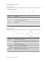
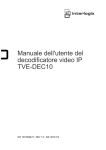
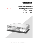
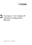
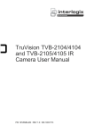
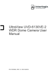
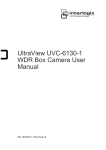
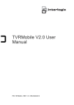
TVE-DEC11 IP Video
Decoder User Manual
P/N 1072901-EN • REV B • ISS 20NOV15
Copyright
© 2015 United Technologies Corporation.
Interlogix is part of UTC Building & Industrial Systems, a unit of
United Technologies Corporation. All rights reserved.
Trademarks and
patents
Manufacturer
Trade names used in this document may be trademarks or
registered trademarks of the manufacturers or vendors of the
respective products.
Interlogix
2955 Red Hill Avenue, Costa Mesa, CA 92626-5923, USA
Authorized EU manufacturing representative:
UTC Fire & Security B.V.
Kelvinstraat 7, 6003 DH Weert, The Netherlands
Certification
FCC compliance
N4131
Class B: This equipment has been tested and found to comply with
the limits for a Class B digital device, pursuant to part 15 of the FCC
Rules. These limits are designed to provide reasonable protection
against harmful interference in a residential installation. This
equipment generates, uses, and can radiate radio frequency energy
and, if not installed and used in accordance with the instructions,
may cause harmful interference to radio communications.
There is no guarantee that interference will not occur in a particular
installation. If this equipment does cause harmful interference to
radio or television reception, which can be determined by turning the
equipment off and on, the user is encouraged to try to correct the
interference by one or more of the following measures:
•
•
•
•
European Union
directives
Reorient or relocate the receiving antenna.
Increase the separation between the equipment and receiver.
Connect the equipment into an outlet on a circuit different from
that to which the receiver is connected.
Consult the dealer or an experienced radio/TV technician for
help.
12004/108/EC (EMC directive): Hereby, UTC Fire & Security
Americas Corporation, Inc., declares that this device is in compliance
or with the essential requirements and other relevant provisions of
Directive 2004/108/EC
2012/19/EU (WEEE directive): Products marked with this symbol
cannot be disposed of as unsorted municipal waste in the European
Union. For proper recycling, return this product to your local supplier
upon the purchase of equivalent new equipment, or dispose of it at
designated collection points. For more information see:
www.recyclethis.info.
Contact information
For contact information, see www.utcfireandsecurity.com or
www.utcfssecurityproducts.eu.
Content
Introduction 2
Package contents 2
Key features 2
Product description 3
Connections 4
Network Settings 6
TruVision Device Manager 6
Using a web browser 9
Before you start 9
Accessing the web browser 9
Decoder operation 10
Dynamic decoding 10
Sequence mode 11
Remote playback 12
Display settings 14
Enable/disable decoding channel 15
Picture overlay 15
Connection status 16
Check decoding channel status 16
Check display channel status 17
Transparent channel 17
Configuration 19
Device properties 19
Time settings 20
Network settings 21
Serial port settings 23
Alarm settings 25
Arming time 26
User account management 26
Import/Export Configure File 28
Device management 29
Specifications 30
TVE-DEC11 IP Video Decoder User Manual
i
Introduction
The TruVision TVE H.264 IP video decoder converts compressed IP video streams
to analog video output for display. Based on a powerful DSP and a stable
embedded system design, the TVE-DEC11 decoder provides a high resolution
decoding function for both live view and playback streams from Interlogix IP
cameras, digital video recorders and network video recorders.
This user manual provides basic information on setting up and using the TVEDEC11 model.
The decoder is shipped with on-screen display (OSD) menus in English and
Chinese.
Package contents
The TruVision TVE H.264 IP video decoder is shipped with the following items:
•
TVE-DEC11 decoder
•
Power adaptor
•
Power cable
•
Quick start guide
•
CD (includes the user manual and TruVision Device Manager)
Key features
The following key features are supported by TVE decoders:
•
Supports compression H.264 and MPEG4 codec
•
Powerful decoding capability:
- 2-channel video stream at 5MP resolution, or
- 4-channel video stream at 1080P resolution, or
- 8-channel video stream at 720P resolution, or
- 16-channel video stream at 960H resolution
•
Multiple video display outputs: You can decode different cameras on either HDMI
and CVBS output, or on VGA and CVBS output
•
Compatible with Interlogix TruVision IP cameras and TruVision recorders. Please
check the Interlogix web site for the latest compatible device list.
•
Supports ONVIF, PSIA and CGI communication
•
Discoverable via the TruVision Discovery Tool
2
TVE-DEC11 IP Video Decoder User Manual
Product description
Figure 1: Front panel
Name
Description
1.
Power
The power LED
2.
Link
Network connection LED
3.
Tx/Rx
Data transmitting/receiving status LED
4.
HDMI
HDMI output
5.
VGA
VGA output
6.
Audio out
RCA Audio output
7.
Video out
BNC output
Figure 2: Rear panel
Name
Description
1.
Line out
Audio output, 3.5mm connector.
2.
Line in
Audio input, 3.5mm connector.
3.
Ethernet
4.
RS-232
Connect the 10M/100M/1000Mbps self-adaptive UTP Ethernet port to a
network.
Connect to an RS-232 device, such as a computer.
5.
RS-485
Connect to RS-485 serial port.
6.
Alarm Input
Connect up to four alarm relay inputs.
Alarm Output
Connect up to four alarm relay outputs.
7.
DC 12V
Connect a 12 V power supply via a PSU.
8.
GND
Connect to ground.
TVE-DEC11 IP Video Decoder User Manual
3
Connections
See Figure 2 on page 3 for information on connecting the power, camera, audio and
network cables.
Alarm connections
The TVE decoder supports the open/close relay input as the alarm input mode.
When the alarm input signal not in open/close relay signal mode, please follow the
connections shown below:
Figure 3: Alarm input connections
Alarm input connections for Emerson alarm:
Alarm input connections for normal alarm:
1. Emerson alarm
4. 4N35 optocoupler
2. V output
5. Relay output
3. 10 V regulator
6. Normal alarm
7. 12 V or 24 V relay
The alarm input can be selected to NO or NC. Different alarm output connection
methods are applied to the AC or DC load. See Figure 3.
4
TVE-DEC11 IP Video Decoder User Manual
Figure 4: Alarm output connections
Note: Please note the different connections of JJ1 shown above. For a DC load,
JJ1can be safely used both in NC and NO methods. It is recommended to use 12 V
/ 1 A. For an external AC input, JJ1 must be open. The motherboard has two
jumpers, each corresponding to one alarm output. Both jumpers are factory set to be
connected.
TVE-DEC11 IP Video Decoder User Manual
5
Network Settings
This chapter explains how to use TruVision Device Manager to find and configure
the IP address and other parameters of the device.
Note: The default user name of TVE is admin, and password is 1234. The default IP
address is 192.168.1.70
TruVision Device Manager
The TruVision Device Manager tool can be found on the CD shipped with that
product.
This tool automatically identifies TruVision devices that support “auto-discovery” in
the same subnets. You can view and modify the IP address of any discovered
device.
To install the TruVision Device Manager:
1. Insert the CD in the computer’s CD/DVD drive.
2. Browse to the folder Tools and double-click the Setup file located in the folder.
3. Click Next.
4. Select the folder where the setup will install the files then click Next.
6
TVE-DEC11 IP Video Decoder User Manual
5. The program requires a utility called WinPcap to be installed on the computer. If
it is already installed, go to step 6.
If the program is not installed, the WinPcap window appears. Follow the onscreen instructions.
6. The TruVision Device Manager Wizard appears. Click Finish to complete its
installation.
Using the TruVision Device Manager
The setup will install the necessary files and place the following shortcut on your
desktop.
Figure 5: TruVision Device Manager shortcut icon
To use the TruVision Device Manager:
1. Double-click the shortcut icon to open the tool.
The Start window appears.
2. The list of TruVision devices located on your network appears.
Note: The TruVision Device Manager can only detect devices that are on the
same LAN. The tool cannot detect devices placed on a VLAN.
TVE-DEC11 IP Video Decoder User Manual
7
The tool identifies:
•
Device type
•
Device MAC address
•
IP address
•
Number of video channels supported by the device
•
Connection port
•
Software version
•
Device serial number
•
DSP/firmware version
•
Device subnet mask
•
Device start time
3. To change the IP address and/or the subnet mask of the device, click the line of
the device address to be changed. The key device characteristics for that device
are listed in the right pane.
4. Change/modify the IP address and or subnet mask as required. Input the
device’s logon password and press Save.
5. Repeat this process for each device that needs to be modified. When all
changes to all discovered devices is complete, press Exit to close the tool.
8
TVE-DEC11 IP Video Decoder User Manual
Using a web browser
You can configure the decoder over the network with a web browser.
The supported web browsers include:
•
Internet Explorer 8 and above
•
Firefox 27.0.1 and above
•
Chrome 33.0.1750 and above
Before you start
•
Before accessing the browser, you need to configure the network settings of
decoder.
•
Connect the decoder to the LAN, and connect a computer to the same LAN as
the decoder.
•
The decoder’s factory default user name is admin and the password is 1234.
•
The decoder’s factory default IP address is 192.168.1.70.
Accessing the web browser
To access the web browser:
1. Open the web browser and enter the IP address of the decoder (for example,
http://192.168.1.70). Press the Enter key on the computer.
The system displays the login window.
2. Enter the user name (default: admin) and password (default: 1234) to log into the
system. The main page of the decoder appears.
3. If you need to install the TruVision Device Manager, You can find the tool on the
CD shipped with the product.
TVE-DEC11 IP Video Decoder User Manual
9
Decoder operation
Use these menus to define how the decoder operates. There are four main
submenus in the decoder menu tree. See Figure 7 below.
Figure 6: Menu tree of Decoding Operation
Decoding Operation
Decode Mode
Dynamic Decoding
Sequence Decoding
Remote Playback
Display Control
Decode Control
Ch Enable/Disable
Picture Overlay
Decoding Status
Connection Status
Decoding Channel
Display Channel
Transparent Channel
Table 1: Description of decoder menus
Function
Description
Decode mode
Select decoding channels and sequence.
•
Configure playback on recorded files.
•
Configure display channel, video format, output resolution
and display mode.
Decode control
Enable/disable a decoding channel, scale video output
image, and configure picture overlay.
Decoding status
Display decoding channel status and video output status.
Transparent channel
Set up transparent data transmission between the encoder
and decoder.
Dynamic decoding
Use this function to set up the parameters of each channel to be decoded.
To set up dynamic decoding:
1. Click Decoding Operation > Decoding Mode > Dynamic Decoding. The
Dynamic Decoding window appears.
10
TVE-DEC11 IP Video Decoder User Manual
2. Enter the channel parameters:
Decoding Camera No.: Select the decode channel.
Manufacturer: Select the manufacturer of the encoding device connected to be
decoded. Encoding devices are supported from TRUVISION and third party
manufacturers.
Remote Host Address: Enter the IP address of the encoding device to be
decoded.
Remote Host Port: Enter the port of the encoding device to be decoded.
Remote Host Camera No.: Enter the channel number of the encoding device to
be decoded.
User Name/Password: Enter the user name and password used to log into the
encoding device.
Transmission protocol: Select the protocol for data transmission: either TCP,
UDP or MCAST.
Stream Type: Set the stream type to be decoded and the default type is main
stream. The substream is supported for decoding when the encoding device
supports dual stream.
3. Click Start Decoding to start decoding.
Sequence mode
Set up the decoder so that the decoded images of multiple streams from a camera
are automatically sequenced with a set dwell time between each image.
To set up the decoding sequence:
1. Click Decoding Operation > Decode Mode > Sequence Decoding. The
Sequence Decoding window appears.
TVE-DEC11 IP Video Decoder User Manual
11
2. Select the channel to be decoded from the Decoding Camera No. drop-down
list.
3. Enter a dwell time in the Dwell Time box. This is the time in seconds that the
image is displayed before moving on to the next one.
4. Click Edit to define the channel parameters. In the window enter the channel
parameters:
Manufacturer: Select the Manufacturer of encoding device connected to be
decoded. Encoding devices are supported from TRUVISION and third party
manufacturers.
Remote IP Address: Enter the IP address of the encoding device.
Remote Port: Enter the port of the encoding device.
Camera No.: Enter the channel number of the encoding device to be decoded.
Protocol: Select the protocol for data transmission, TCP, UDP or MCAST.
Stream Type: Select the stream type to decode, either main stream or substream.
Note: Up to 64 cameras can be decoded in sequence.
5. Click Save to save the settings and return to the previous window.
Remote playback
Use this function to remotely access the encoder or recorder to stream and decode
stored files for local output.
To set up remote playback:
1. Click Decoding Operation > Decode Mode > Remote playback. The Remote
Playback window appears.
12
TVE-DEC11 IP Video Decoder User Manual
2. Select the channel for playback from the Decoding Camera No. drop-down list.
3. Enter the channel parameters:
Remote Host Address: Enter the IP address of the encoding device.
Remote Host Port: Enter the port of the encoding device.
Remote Host Port: Enter the port of the encoding device.
Remote Host Camera No.: Enter the channel number of the encoding device to
be decoded.
User Name/Password: Enter the user name and password used to log into the
encoding device.
Playback by File: Enter the file name of the file to be played back from the DVR.
This is found from a search of the stored files on the DVR.
Playback by Time: Enter the start and end time of the file to be played back.
4. Click Save to save the settings.
5. Click
to start playback.
Control playback by using the buttons on the toolbar
. Click
to start, stop, slow forward, fast forward and turn audio on/off respectively.
Slow forward is 1/2X, 1/4, 1/8X and minimum. Fast forward is 2X, 4X, 8X and
16X.
TVE-DEC11 IP Video Decoder User Manual
13
Display settings
Use this window to configure the display channel, video format, output resolution
and display mode. There are three display mode formats; full screen, 4-screen, 9screen and 16-screen.
The decoder automatically detects the video mode (PAL/NTSC).
To set up the display settings:
1. Click Decoding Operation > Decode Mode > Display Control. The Display
Control window appears.
2. Click one of the output display buttons to select the output required: VGA, HDMI
or BNC.
Depending on the option selected the options displayed in the monitor property
window may change.
Note: You can decoder different cameras to either HDMI and CVBS output, or
to VGA and CVBS output.
3. Select the output resolution from the drop-down list.
4. Select the display mode from the drop-down list.
5. Under the Tile Monitor Property window, select which video tile on the monitor
is associated with which channel. This option depends on the output display
option selected.
Click the
and
icons to enable or disable audio and image scaling
respectively for each channel.
6. Click Save to save the settings.
14
TVE-DEC11 IP Video Decoder User Manual
Enable/disable decoding channel
Use this window to enable or disable a decoding channel. The decoding channel
parameters remain unchanged.
To enable or disable a decoding channel:
1. Click Decoding Operation > Decode Control > Ch Enable/Disable. The Ch
Enable/Disable window appears.
2. Select the desired decoding channel from the drop-down list.
3. In the On/Off box, enable or disable the selected channel.
4. Click Save to save the settings.
Picture overlay
Use this function to overlay a picture on a decoded channel display. The picture can
be positioned anywhere on screen.
The picture must have a 24-bit BMP format. Its height and width should be 32X
pixel. A resolution up to 128 x 128 is supported.
To set up picture overlay:
1. Click Decoding Operation > Decode Control > Picture Overlay. The Picture
Overlay window appears.
Select the desired decoding channel from the drop-down list.
TVE-DEC11 IP Video Decoder User Manual
15
2. In the Select Picture box, browse the desired picture and click Upload to upload
it.
3. Enter the X and Y co-ordinates to position the picture on screen.
4. Select how you want the picture displayed. Check Flash to have a picture that
flashes. If you want the picture to be transparent, disable Show this picture.
5. Click Save to save the settings.
Connection status
Use this menu to configure the channel used by the decoder for decoding and live
view. The information is regularly updated automatically.
To view the connection status:
1. Click Decoding Operation > Decoding Status > Connection Status. The
Connection Status window appears.
2. Enter values for the following parameters:
Decoding Camera No.: Enter the channel to be decoded.
Connection Status: Check the status of the decoding channel that is streaming
video from an encoding device.
Bitrate Transmission Rate: View the bit rate of the stream being decoded.
Get Stream Properties: The TruVision decoder can only support active mode. It
actively tries to get video streams from an encoder or NVR.
Check decoding channel status
Use this menu to check the current decoding channel for information such as the
channel number, decoding channel status, stream compression type and video
frame rate, for example. The information is regularly updated automatically.
16
TVE-DEC11 IP Video Decoder User Manual
To view the channel status:
1. Click Decoding Operation > Decoding Status > Decoding Channel. The
Decoding Channel window appears that lists the current status for all cameras.
Check display channel status
Use this menu to check the configuration information on the current channel. The
information is regularly updated automatically.
To view the channel status:
1. Click Decoding Operation > Decoding Status > Display Channel. The
Display Channel window appears.
Transparent channel
Use this menu to set up the transmission of transparent data between the encoder
and decoder. The decoder uses the RS-232 or RS-485 serial port to send
transparent data over the network.
Up to 64 encoders can be used to address a decoder.
Note: If RS-232 is selected as the local serial port, you must set up the operation
mode as transparent under Configuration > Serial Port Parameters > RS-232.
TVE-DEC11 IP Video Decoder User Manual
17
To set up the transparent channel:
1. Click Decoding Operation > Transparent Channel. The Transparent Channel
window appears.
2. Enter values for the following parameters:
Local Serial Port: Select the decoder’s serial interface from the drop-down list:
RS-232 or RS-485.
Remote Serial Port: Select the remote encoding device’s serial interface from
the drop-down list: RS-232 or RS-485.
Remote Host Address: Enter the IP address of the remote encoding device.
Remote Host Port: Enter the host port of the remote encoding device.
User Name and Password: Enter the user name and password used to log into
the encoding device.
3. Click Save to save the settings.
18
TVE-DEC11 IP Video Decoder User Manual
Configuration
Use these menus to configure the decoder.
Figure 7: Menu tree of Configuration
Configuration
Device Properties
Time Settings
Network Settings
General
DDNS
Telnet
Serial Port Settings
RS-232 Port
RS-485 Port
Alarm Settings
Alarm Input
Alarm Output
Arming Time
User Management
Config File Import/Export
Function
Description
Device Properties
Define the decoder name.
Display the decoder serial number and firmware version.
Time Settings
Define the device time
Network Properties
Define network settings.
Serial Port Settings
Define the serial port properties.
Alarm Settings
Configure alarm input/output settings and notification
method.
Arming Time
Define alarm schedules.
User Management
Create, modify or delete users and allocate user
permissions.
Config File Import/Export
Import/export configuration files.
Device properties
You can edit the decoder name and view the decoder type and serial number as well as
firmware version.
TVE-DEC11 IP Video Decoder User Manual
19
To set up the decoder properties:
1. Click Configuration > Device Properties. The Device Properties window
appears.
2. Enter the device name.
The other options are read-only:
Physical address: View the MAC address of the decoder. It is unique and cannot
be changed.
Device type: View the decoder model name.
Device Serial No.: View the decoder serial number.
Firmware version: View the firmware version number installed in the decoder.
DSP version: View the software version number used in the DSP.
3. Click Save to save the settings.
Time settings
You can set up the decoder to use a Network Time Protocol (NTP) server to keep
the date and time current and accurate or manually select the local time zone.
Note: If the decoder is connected to a public network, you should use a NTP server
that has a time synchronization function, such as the server at the National Time
Center (IP Address: 210.72.145.44) or europe.ntp.pool.org. If the encoder is set up
in a more customized network, NTP software can be used to establish a NTP server
used for time synchronization.
To set up the decoder properties:
1. Click Configuration > Time Settings. The Time Settings window appears.
20
TVE-DEC11 IP Video Decoder User Manual
2. Check NTP and enter the IP address of the NTP server and the NTP port value.
- Or Check Manual Time Sync and Time Zone Settings. Select the time zone that
is closest to the device’s location from the drop-down list.
3. Click Save to save the settings.
Network settings
You must configure your decoder’s network settings before using it over the
network.
To configure general settings:
1. Click Configuration > Network Settings > General. The General Network
Settings window appears.
2. Enter the required values for the following options:
TVE-DEC11 IP Video Decoder User Manual
21
Option
Description
IPv4 address
Enter the IP address for the decoder.
The default IP address is 192.168.1.70.
IPv4 Subnet mask
Enter the subnet mask for your network so the decoder will
be recognized within the network.
Default value is 255.255.255.0.
IPv4 Gateway address
Enter the IP address of your network gateway so the
decoder will be recognized within the network. This is
typically the IP address of your router.
Default value is 0.0.0.0.
DNS server
Enter the domain name server to use with the decoder.
Default value is 0.0.0.0.
3. Click Save to save the settings.
To configure DDNS settings:
If your device is set to use PPPoE as its default network connection, you may set
Dynamic DNS (DDNS) to be used for network access.
Prior registration with your DDNS Provider is required before configuring the system
to use DDNS.
1. Click Configuration > Network Settings > DDNS. The DDNS window appears.
2. Check the Enable DDNS checkbox to enable this feature.
3. Select the DDNS Type from the drop-down list. Four different DDNS types are
selectable: IPServer, DynDNS, PeanutHull, NO-IP and ezDDNS.
4. Enter the Server Address and Port for DDNS Server.
5. Enter the User Name and Password that you applied from the server.
6. Click Save to save the settings.
22
TVE-DEC11 IP Video Decoder User Manual
To configure Telnet settings:
1. Click Configuration > Network Settings > Telnet. The Telnet window appears.
2. Check the Enable Telnet checkbox.
3. Enter the Telnet Password and confirm it.
4. Click Save to save the changes.
Note:
1. The Telnet user name is “root” as default, and cannot be changed.
2. The default Telnet password is “ab12!”
3. The password should be set with at least 4-character password with at least one
letter and one number.
Serial port settings
Use this menu to configure the settings of the RS-232 and RS-485 ports.
To set up RS-232 port:
1. Click Configuration > Serial Port Settings > RS-232 Port. The RS-232 Port
window appears.
TVE-DEC11 IP Video Decoder User Manual
23
2. Input the values for the following parameters: RS-232 port, duplex mode, baud
rate, data bit, stop bit, parity type, and operation mode.
3. Click Save to save settings.
To set up RS-485 port:
1. Click Configuration > Serial Port Settings > RS-485 Port. The RS-485 Port
window appears.
2. Input the values for the following parameters: RS-485 camera number, duplex
mode, baud rate, data bit, stop bit, and parity type.
3. Click Save to save settings.
24
TVE-DEC11 IP Video Decoder User Manual
Alarm settings
The decoder can be configured on how it will respond when an alarm input is
triggered by an external alarm device (for example, PIR detector, dry contacts…).
To set up alarm inputs:
1. Click Configuration > Alarm Settings > Alarm Input. The Alarm Input window
appears.
2. Under Alarm Input, select the alarm input number of a camera.
3. Under Alarm Sensor Type, select the alarm input type: NO (normally open) or
NC (normally closed).
4. Under Alarm Input Rule, check one or more of the desired response methods:
Alarm Output 1 to Alarm Output 4.
5. Click Save to save settings.
To set up alarm outputs:
1. Click Configuration > Alarm Settings > Alarm Output. The Alarm Output
window appears.
TVE-DEC11 IP Video Decoder User Manual
25
2. Select an alarm output from the drop-down list.
3. Under Output Delay, select a time out option from the drop-down list.
The time out setting lets you define for how long a signal remains active after
the alarm has ended. Select a time out option: 5, 10, and 30 seconds, 1, 2, 5,
and 10 minutes, and Manual stop. If “Manual stop” is selected, the alarm output
will stop only when the alarm input is manually stopped.
4. Click Save to save settings.
Arming time
You can set up to eight arming schedules for alarm inputs.
To set up the arming schedules:
1. Click Configuration > Arming Time. The Arming Time window appears.
2. Select the day of the week and the start and end time periods during the day
when the alarm inputs and outs are armed. You can schedule up to eight time
periods in a day. Default is 24 hours.
Note: The time periods defined cannot overlap.
3. Click Save to save settings.
User account management
By default the decoder comes with an administrator user account. The administrator
can add, modify or delete users.
The Administrator can add, delete or configure parameters for all decoder functions.
There can only be one administrator. The user name is admin. The name cannot be
modified. The default password is 1234.
Note: Default passwords should be changed for security reasons.
26
TVE-DEC11 IP Video Decoder User Manual
To add a new user:
1. Click Configuration > User Management. The User Management window
appears.
Note: Only a system administrator can create a user. You can add up to 31 new
users.
2. Click Add and enter the user name and password. Both the user name and
password can have up to 16 alphanumeric characters.
3. Under “User Permission”, select the desired user access privileges.
4. Click OK.
To modify a user:
1. Click Configuration > User Management. The User Management window
appears.
Note: Only a system administrator can modify a user.
2. Select the desired user and click Modify.
3. Modify the user access privileges.
4. Click OK.
To delete a user:
1. Click Configuration > User Management. The user Management window
appears.
2. Select the desired user and click Delete.
3. Click OK in the pop-up window to confirm deletion. The user is immediately
deleted.
4. Click OK.
TVE-DEC11 IP Video Decoder User Manual
27
Import/Export Configure File
The configuration files of the device can be imported from or exported to a local
device for backup. This is useful if you want to copy the configuration settings to
another device, or if you want to make a backup of the settings.
To import/export config file:
1. Click Configuration > Config File Import/Export. The Config File
Import/Export window appears.
2. Click Browse to select the file from the local directory and then click the Import
button to import a configuration file.
-OrClick the Export button to export configuration files to the local backup device.
28
TVE-DEC11 IP Video Decoder User Manual
Device management
Use this window to update the decoder firmware, restore factory default settings and
reboot the device.
Note: Any changes to the default passwords will be lost after a factory reset or
firmware upgrade.
To update the firmware:
1. Click Device Management > Upgrade. The Upgrade window appears.
2. Under “Upgrade File”, click Browse to locate the upgrade file from a local backup device. Click Upgrade to start importing.
To restore factory default settings:
1. Click Device Management > Restore Default. The restore default window
appears.
2. Click Complete to restore all factory settings including IP address and network
settings.
- Or Click Simple to restore factory settings except for IP address and network
settings.
The default settings are restored immediately.
To restart the decoder:
1. Click Device Management > Reboot. The Reboot window appears.
2. Click OK. The decoder restarts.
TVE-DEC11 IP Video Decoder User Manual
29
Specifications
Model
TVE-DEC11
Video/audio
output
CVBS output
1-channel BNC output
VGA output
1-channel VGA output
Resolution:
1920×1080@60 / 50HZ,
1600×1200@60Hz,
1280×1024@60Hz,
1280×720@50/60Hz,
1024×768@60Hz
HDMI output
1-channel HDMI output
Resolution:
1920×1080@60 / 50HZ,
1600×1200@60Hz,
1280×1024@60Hz,
1280×720@50/60Hz,
1024×768@60Hz
Video/audio
decoding
Audio output
1-channel, RCA
IP video input
H.264 / MPEG4
Multi-division display mode
1 / 4 / 9 /16
Frame rate
25 fps (PAL) / 30 fps (NTSC)
Audio compression
G.722 / G.711A / G.711U / MPEG2-L2 /
ACC
Network interface
1 RJ45 10/100/1000 Mbps
Self-adaptive Ethernet interface
External
interface
General
30
Serial interface
1 RS-485 and & 1 RS-232 serial interface
Bidirectional audio input
2-ch, 3.5mm connector (2.0 Vp-p, 1 kΩ)
Alarm inputs
4
Alarm outputs
4
Power supply
12 VDC
Consumption
Max. 15W
Operating temperature
-10 to +55 °C (14 to 131 °F)
Operating humidity
10% to 90%
Dimension (W ×D × H)
220×180×45 mm (8.66 × 7.1 × 1.77 in.)
Weight
1.12 kg (2.47 lb.)
TVE-DEC11 IP Video Decoder User Manual