1
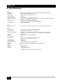
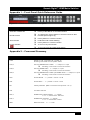
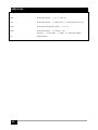
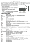
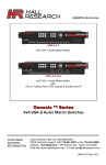
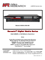
User’s Manual Model HSM-I-08-08 Genesis™ Digital Matrix Series 8x8 HDMI or DVI Matrix Switcher With Audio De-embedding & Independent Routing Built-in Server for Configuration & Control RS-232, IP, and Front panel Controls HDMI 1.4 Deep-color & 3D Support HDCP compliant with EDID Management Fast-Switch™ Technology CUSTOMER SUPPORT INFORMATION Order toll-free in the U.S. 800-959-6439 FREE technical support, Call 714-641-6607 or fax 714-641-6698 Address: Hall Research, 1163 Warner Ave. Tustin, CA 92780 Website: www.hallresearch.com E-mail: [email protected] UMA1199 Rev 1.0 Genesis Digital™ HDMI Matrix Switches TRADEMARKS USED IN THIS MANUAL Hall Research and its logo are trademarks of Hall Research. Any other trademarks mentioned in this manual are acknowledged as the property of the trademark owners. FEDERAL COMMUNICATIONS COMMISSION RADIO FREQUENCY INTERFERENCE STATEMENT This equipment generates, uses, and can radiate radio frequency energy and if not installed and used properly, that is, in strict accordance with the manufacturer’s instructions, may cause interference to radio communication. It has been designed to comply with the limits for a Class A computing device in accordance with the specifications in Subpart B of Part 15 of FCC rules, which are intended to provide reasonable protection against such interference when the equipment is operated in a commercial environment. Operation of this equipment in a residential area is likely to cause interference, in which case the user at their own expense will be required to take whatever measures may be necessary to correct the interference. Changes or modifications not expressly approved by the party responsible for compliance could void the user’s authority to operate the equipment. 1 HSM-I-08-08 Contents 1. Introduction............................................................................................................ 4 1.1 General .................................................................................................................. 4 1.2 Features ................................................................................................................ 5 2. Installation.............................................................................................................. 6 2.1 Package Contents ................................................................................................. 6 2.2 Input and Output Connections ............................................................................... 6 2.2 Connection Block Diagram .................................................................................... 8 3. Configuration & Operation ................................................................................... 9 3.1 Front-Panel Buttons and Indicators ....................................................................... 9 3.2 Turning the unit on and off..................................................................................... 9 3.3 Making AV Routings or “Ties” from Front Panel .................................................. 10 3.4 Saving Presets (routing patterns) ........................................................................ 11 3.5 Recalling Presets (routing patterns) .................................................................... 11 4. Control Commands (RS-232 and IP) .................................................................. 12 4.1 Routing Functions................................................................................................ 12 4.2 Preset Save and Recall Functions....................................................................... 14 4.3 Power Functions .................................................................................................. 15 4.4 Factory Defaults .................................................................................................. 15 4.5 Firmware Version ................................................................................................ 16 4.6 HDMI Output (Blank Video & Mute Audio)........................................................... 16 4.7 HDMI Audio ......................................................................................................... 16 4.8 Menu Contrast ..................................................................................................... 16 4.9 Naming Input ....................................................................................................... 17 4.10 On Screen Display ............................................................................................. 17 4.11 On Screen Display Timer .................................................................................. 17 4.12 On Screen Display Box...................................................................................... 17 4.13 HDCP ................................................................................................................ 17 4.14 Current Status ................................................................................................... 18 4.15 Error Commands ............................................................................................... 18 5. IP Control Basics ................................................................................................. 19 5.1 Getting Device IP Address................................................................................... 20 5.2 Controlling the Matrix via Web Interface .............................................................. 20 5.3 IP Specific Serial Commands .............................................................................. 30 6. Telnet Interface .................................................................................................... 31 6.1 Telnet Interface Commands ................................................................................ 32 2 Genesis Digital™ HDMI Matrix Switches 7. Troubleshooting .................................................................................................. 32 7.1 Contacting Hall Research .................................................................................... 32 7.2 Shipping and Packaging ...................................................................................... 33 8. Specifications ...................................................................................................... 34 Appendix 1 – Front Panel Quick Reference Guide ............................................... 35 Appendix 2 – Command Summary ........................................................................ 35 3 HSM-I-08-08 1. Introduction 1.1 General Thank you for purchasing this professional quality and compact digital matrix switch from Hall Research. As a member of Hall’s renowned Genesis™ Series, this matrix is synonymous with high performance, intuitive and powerful user interface, easy to use control command set, and unsurpassed reliability. The matrix is an 8x8 cross-point switch in a compact 1-RU enclosure. It supports HDMI 1.4a for 3D format and supports deep-color to 12 bits per component (36-bit color routing), supports HDCP, PCM, Dolby, DTS, and HD audio standards. It may be used with any combination of DVI (PC) or HDMI (HDTV) sources and displays. The matrix switch automatically performs intelligent EDID capability mapping between sinks and sources. The EDID’s audio and video capabilities are computed from a combination of downstream capabilities being ANDed together to form an EDID table for reporting to video sources in order to guarantee all displays will be able to show the image from any source. The Model HSM-I-08-08 also features “Fast Switching” technology whereby all sources are kept active even if they are not routed to any sinks. The matrix inputs perform all the EDID and HDCP handshakes with all connected sources continuously. Compared with low-cost switchers, this method reduces switching time by several seconds. Proprietary handling of downstream HDCP device keys, assures compliance with HDCP without limiting the number of outputs that can be routed to the same input. Furthermore, each output of the matrix can handle over 20 downstream keys simultaneously. OSD display of user defined input names with user definable OSD position and duration, brings a new degree of sophistication and user friendliness to the Genesis™ Series. The matrix features embedded HTML5 server to allow configuration and real-time control from any browser, tablet or smart-phone. No app or software is needed as all software resides in the matrix itself. The smart server renders pages specifically configured for the device it is being displayed on, producing a perfect GUI on a small phone or on a big tablet automatically. We call this a “pseudo app”, since it works like an app, but with nothing to install other than a shortcut to the ip address. The web interface allows the user to assign custom names for each input, output, and preset pattern, making control over IP a snap. Other features include: PRESET save and recall functions (with user definable PRESET names), HDMI output blanking, HDMI audio extraction and independent routing to SPDIF outputs, ability to remove audio from HDMI outputs, comprehensive front panel controls, RS-232 and Telnet control. The HSM-I-08-08 Genesis™ Digital matrix is ideal for home theater, conference room, multimedia presentation, digital signage in retail space, and other similar settings. 4 Genesis Digital™ HDMI Matrix Switches 1.2 Features • Compatible with HDMI version 1.4a (for color-depth and 3D), and DVI • HDMI Audio De-embedding & Independent Routing to SPDIF outputs • Supports a wide range of HDTV (HDMI) and PC (DVI) resolutions from 480i to 1080p and VGA to WUXGA • Supports digital video formats in Deep Color to 12bit per color • Supports lossless digital audio: both 5.1 and 7.1 Dolby TrueHD, Dolby Digital Plus and DTS-HD Master Audio • Front panel LCD readout for easy setup and control • Preset Save and Recall of commonly used routing patterns • Intelligent EDID capability mapping • Audio and video compatibility among multiple sink devices • All HDMI inputs on the unit include cable equalization to support up 20 meters of input cable with 1080p sources • OSD video overlay to show user defined channel name on each output after it is switched to a new input • HDMI video output can be blanked or un-blanked • HDMI embedded audio output can be active or muted • Includes RS-232 port with Hall Research’s Genesis Control Command Set (GCCS) • IP (LAN) port includes web-server with easy to use controls (customizable with user definable names for each input and output) • Telnet interface using the same RS-232 commands (GCCS) • 1RU high compact & rugged rack mountable metal enclosure • Full ESD protection is implemented on all HDMI connectors • Incorporates “Fast Switching” technology to reduce blanking time • Designed and made in USA 5 HSM-I-08-08 2. Installation 2.1 Package Contents Your package should contain the 1RU Matrix Switcher, a Universal power supply (12v DC @ 6A), an IEC320 Power Cord, and a User’s Manual. Figure 1 – Power Supply Notice Use only regulated 12v DC supply (center positive) as supplied with the unit. Use of any other voltage will cause damage to the unit and void the warranty. 2.2 Input and Output Connections The matrix is housed in a 1RU 19” wide rack mountable enclosure. All of I/O, control, and the power connections are on the rear of the unit. Figure 2 – Rear Panel Connections (for HSM-I-08-08) 6 Genesis Digital™ HDMI Matrix Switches Using quality HDMI cables connect the inputs to video sources. If the sources are DVI (PC) then you will need either a DVI to HDMI adapter, or preferably, a DVI to HDMI Cable Figure 3 – Model C-HDMI-DVI-xM (x = 2, 3 or 5 meters) For a professional installation, we recommend using locking HDMI cables. The Matrix Switch has a tapped hole above each HDMI connector and the locking cables available from Hall Research come with screws and standoffs for securing the cables in place so they don’t accidentally get unplugged Figure 4 – Model C-HDMI-L-x (x = 1.5, 3, 6, 10, 15, 25, 35 or 50 ft) Next, connect the HDMI outputs to the displays. Plug the power supply to the unit. Use only the supply that came with the unit If the matrix needs to be controlled via RS-232, plug the controller (or PC) to the DB9 Female port on the rear of the matrix. Connection to PC’s DB9 Male is made using a straight through DB9 Male-to-Female cable (as shown below). This port operates at a baud rate of 115,200. Table 1 – RS-232 Control Port Pinout To control the matrix via the IP port, just connect an RJ45 cable to your Local Area Network (LAN). This unit features a user friendly and powerful 7 HSM-I-08-08 built-in web-server that allows control of the matrix via any browser using web enabled controllers. 2.2 Connection Block Diagram Figure 5 – Connection Block Diagram Figure 6 – On Screen Display of user defined input names after switching (position and duration is configurable) 8 Genesis Digital™ HDMI Matrix Switches 3. Configuration & Operation 3.1 Front-Panel Buttons and Indicators An image of the front panel for the 8x8 matrix is shown below. Figure 7 – HSM-I-08-08 front panel controls & indicators The front panel can be used for the following purposes: • Monitor & Control Power On/Off status • View current Input/output routings (ties) on LCD • Make new ties either starting from input or from output • Recall preset patterns • Save preset patterns All of the front panel switches have built-in LEDs that help in the operation. Front panel functions are designed for maximum intuitiveness. With just a little practice, one can easily learn to monitor and control the matrix. 3.2 Turning the unit on and off To turn the unit on, press the power button. Then, the matrix will recall the last routing pattern prior to being shut-down along with the last state of VID & AUD buttons. If the VID button is on, the current HDMI input and output routing pattern will be shown on the LCD. If the AUD button is on, the current SPDIF audio output routing pattern will be shown on the LCD. The SPDIF audio output is extracted from the HDMI input port. When both the VID & AUD buttons are on, the LCD will alternate between the display of the HDMI I/O routing pattern and SPDIF audio output routing pattern. The HDMI I/O routing pattern will have a small letter v next to its input number, and the SPDIF audio output routing pattern will have a small letter A next to its input number as shown below. 1v 2v 3v 4v 5v 6v 7v 8v HDMI I/O routing pattern 1A 2A 3A 4A 5A 6A 7A 8A SPDIF audio output routing pattern 9 HSM-I-08-08 If neither the VID nor the AUD button is on, the following screens will be displayed and alternated every 3 seconds. To View/Route AV Use VID/AUD Btns To turn the Matrix off, press and hold the power button for 3 seconds. This is done as a precaution, so that if the power button is accidentally touched, it will not turn off the matrix! When the Matrix is off, the following screens will be shown on the LCD. Standing By … Press PWR to turn on 3.3 Making AV Routings or “Ties” from Front Panel To make the unit as convenient and intuitive as possible the HSM matrix allows you to make ties starting from the input channel’s point of view or from the output. 3.3.1 Making a tie starting from the output This is the most natural way of making connections since each output gets is signal from only one input. 10 Press one of the output channel buttons. That output button will light up along with an input button it is being routed from. If you do not want to make any changes, just hit SET. If you want to change to another output channel, use either the up and down (▲▼) buttons to walk through other outputs; or just select another output channel. The up and down (▲▼) buttons can also be pressed and held to quickly view all output channels one by one. To route the output to a different input than the one currently connected to, hit the “candidate” input channel number. This does not actually make the connection; the new input channel will be blinking. Again if you change your mind, either hit the same blinking button (it will stop blinking), or hit another input channel. When you are sure you have selected the input channel you desire, hit SET. The output can’t be disconnected from the input. It is always being routed from one of the inputs. Note that once you enter the channel routing mode from the front panel, if you do not hit any buttons for approximately 8 seconds, the system will exit this mode without any user interaction. Genesis Digital™ HDMI Matrix Switches NOTE HDMI video output blank/un-blank and embedded audio output active/un-active can ONLY be performed through RS-232 commands or web browser interface. When the HDMI video of a selected output is blanked, the embedded audio associated with that output will be muted. 3.3.2 Making a tie starting from the input The procedure is similar to the above but a particular input can be routed to more than one output or none at all! Press one of the input channel buttons. That button will light up along with ALL the outputs routed from that input. If you want to change to another input channel, use either the up and down (▲▼) buttons to walk through other inputs; or just select another input channel. The up and down (▲▼) buttons can also be pressed and held to quickly view all input channels one by one. To route the selected input to multiple outputs, press the desired output buttons. Again, these new outputs are only “candidates” (will be blinking) and will not be routed until you hit SET. Any outputs tied to this selected input can’t be disconnected from it. 3.4 Saving Presets (routing patterns) The number of presets accessible from the front panel is the same as the total # of input buttons. Each front panel input button can memorize a pattern. Therefore, you can recall 8 presets. Current tie configurations can be saved as presets (1 through 8) for later recall. To save the current AV routing pattern, press and hold the PRE button for 3 sec, the backlit LED will start flashing (this means that save function is activated). Press the desired input button to save the preset then press the SET button to complete the operation. 3.5 Recalling Presets (routing patterns) Press and release the PRE (preset) button. The button will light up solid. Then press and release one of the input channel buttons and hit SET. 11 HSM-I-08-08 4. Control Commands (RS-232 and IP) The Genesis™ Matrix can be controlled via an external control system by using either the standard RS-232 or the optional IP port. Any program capable of standard serial communication in ASCII format is capable of working with the matrix. Most PCs with Windows™ OS have HyperTerminal™ or equivalent. There are also many free Terminal Emulator software programs available for download on the internet. Note on RS-232 port availability on PC Most PCs and notebooks do not come equipped with a serial RS-232 port. Therefore, for serial control from a PC you may need a USB to RS-232 converter. These are available from Hall Research (Model USB-RS232-1) Use a DB9 Male-to-Female cable per Table 1 to connect the unit to the PC’s serial port. Use 115,200 Baud, 8 bits, No Parity, 1 Stop bit, No flow control. Upon power up, the Matrix will output a screen similar to the figure below through its serial port if the unit was previously on. PW1 <cr> CV1,m <cr> CV2,m <cr> CV3,m <cr> CV4,m <cr> CV5,m <cr> CV6,m <cr> CV7,m <cr> CV8,m <cr> CA1,m <cr> CA2,m <cr> CA3,m <cr> CA4,m <cr> CA5,m <cr> CA6,m <cr> CA7,m <cr> CA8,m <cr> Power is on HDMI audio & video output 1 routed to input m HDMI audio & video output 2 routed to input m HDMI audio & video output 3 routed to input m HDMI audio & video output 4 routed to input m HDMI audio & video output 5 routed to input m HDMI audio & video output 6 routed to input m HDMI audio & video output 7 routed to input m HDMI audio & video output 8 routed to input m SPDIF audio output 1 routed to input m SPDIF audio output 2 routed to input m SPDIF audio output 3 routed to input m SPDIF audio output 4 routed to input m SPDIF audio output 5 routed to input m SPDIF audio output 6 routed to input m SPDIF audio output 7 routed to input m SPDIF audio output 8 routed to input m (Where input m = 1-8) If the unit was previously off, it would not output anything through its RS232 port. 4.1 Routing Functions Video routing commands specified are from the point of view of the output. The wildcard character (*) is acceptable for output (but not input). In addition, these commands can be used to monitor or query the status of system ties. Omitting the input channel will result in a response of the current routing for that output. 12 Genesis Digital™ HDMI Matrix Switches Important Note on Control Commands Almost all commands issued to the Matrix will elicit a response from the Matrix once the command is accepted and execution completed. 4.1.1 Make HDMI Audio & Video ties: Command: Response: Query: Command: Response: Command: Response: Command: Response: CVn,m<cr> CVn,m<cr> stands for Connect HDMI Audio & Video Output n to input m (where n = output [1-8], m = input [1-8]) CVn<cr> CVn,m<cr> stands for Connect HDMI Audio & Video Output n Query (where m = input [1-8]) CV*,m<cr> CV1,m<cr> CV2,m<cr> CV3,m<cr> CV4,m<cr> CV5,m<cr> CV6,m<cr> CV7,m<cr> CV8,m<cr> stands for Connect All HDMI Audio & Video Outputs to input m (where * = all outputs) CV*<cr> CV1,m<cr> CV2,m<cr> CV3,m<cr> CV4,m<cr> CV5,m<cr> CV6,m<cr> CV7,m<cr> CV8,m<cr> stands for Connect All HDMI Audio & Video Output Query (where * = all outputs , m = input [1-8]) 4.1.2 Make SPDIF Audio ties: Command: Response: Query: Command: Response: Command: Response: Command: Response: CAn,m<cr> CAn,m<cr> stands for Connect SPDIF Audio Output n to input m (where n = output [1-8], m = input [1-8]) CAn<cr> CAn,m<cr> stands for Connect SPDIF Audio Output n Query (where n = output [1-8], m = input [1-8]) CA*,m<cr> CA1,m<cr> CA2,m<cr> CA3,m<cr> CA4,m<cr> CA5,m<cr> CA6,m<cr> CA7,m<cr> CA8,m<cr> stands for Connect All SPDIF Audio Outputs to input m (where * = all outputs , m = input [1-8]) CA*<cr> CA1,m<cr> CA2,m<cr> stands for Connect All SPDIF Audio Query Output (where * = all outputs , m = input [1-8]) 13 HSM-I-08-08 CA3,m<cr> CA4,m<cr> CA5,m<cr> CA6,m<cr> CA7,m<cr> CA8,m<cr> 4.1.3 Make HDMI Audio & Video ties plus SPDIF Audio ties: Command: Response: Query: Command: Response: Command: Response: Command: Response: COn,m<cr> COn,m<cr> stands for Connect Output n to input m (where n = output [1-8], m = input [1-8]) COn <cr> COn,m<cr> stands for Connect Output n Query (where n = output [1-8], m = input [1-8]) CO*,m<cr> CO1,m<cr> CO2,m<cr> CO3,m<cr> CO4,m<cr> CO5,m<cr> CO6,m<cr> CO7,m<cr> CO8,m<cr> stands for Connect All Outputs to input m (where * = all outputs , m = input [1-8]) CO*<cr> CV1,m<cr> CV2,m<cr> CV3,m<cr> CV4,m<cr> CV5,m<cr> CV6,m<cr> CV7,m<cr> CV8,m<cr> CA1,m<cr> CA2,m<cr> CA3,m<cr> CA4,m<cr> CA5,m<cr> CA6,m<cr> CA7,m<cr> CA8,m<cr> stands for Connect All Outputs Query (where * = all outputs , m = input [1-8]) 4.2 Preset Save and Recall Functions Command: Response: 14 PRx<cr> CV1,m<cr> CV2,m<cr> CV3,m<cr> CV4,m<cr> CV5,m<cr> stands for Preset Recall (where x = preset 1~ 8, m = input [1-8]) Genesis Digital™ HDMI Matrix Switches CV6,m<cr> CV7,m<cr> CV8,m<cr> CA1,m<cr> CA2,m<cr> CA3,m<cr> CA4,m<cr> CA5,m<cr> CA6,m<cr> CA7,m<cr> CA8,m<cr> Command: Response: PSx<cr> PSx<cr> stands for Preset Save (where x = preset 1~ 8) 4.3 Power Functions Command: Response: PW1<cr> stands for Power On (where m = input [1-8]) PW1<cr> CV1,m<cr> CV2,m<cr> CV3,m<cr> CV4,m<cr> CV5,m<cr> CV6,m<cr> CV7,m<cr> CV8,m<cr> CA1,m<cr> CA2,m<cr> CA3,m<cr> CA4,m<cr> CA5,m<cr> CA6,m<cr> CA7,m<cr> CA8,m<cr> Important Note on Power ON Command This command can take up to 6 seconds to complete. Upon powering up the unit will recall the previous state of each output prior to powering off and restore each connection. Command: Response: Query: Command: Response: PW0<cr> PW0<cr> PW<cr> PWx<cr> stands for Power Off stands for Power Query x=0 (off), or 1 (on) 4.4 Factory Defaults Command: Response: FD<cr> FD<cr> stands for Factory Defaults 15 HSM-I-08-08 Issuing a factory Defaults command will set all current and preset HDMI Audio/Video ties plus SPDIF Audio ties 1 to 1 as if issuing a command COn,m where n = m = 1-8. Holding the PWR button down for 1 second while powering up the HSM Matrix will also perform a Factory Defaults. 4.5 Firmware Version Command: Response: FW<cr> stands for Firmware Version FP Version:x.x<cr> Front Panel Firmware Version Main Version:x SW:x.xx<cr> Main Firmware Version Input Version:x SW:x.xx<cr> Input Firmware Version Output Version:x SW:x.xx<cr> Output Firmware Version 4.6 HDMI Output (Blank Video & Mute Audio) Command: Response: Query: Command: Response: HOn,x<cr> HOn,x<cr> stands for HDMI Video & Audio output (where n = output [1-8], x=[0-1] = [disconnect-connect]) HO*,x<cr> HO1,x<cr> HO2,x<cr> HO3,x<cr> HO4,x<cr> HO5,x<cr> HO6,x<cr> HO7,x<cr> HO8,x<cr> stands for HDMI Video & Audio output (where * = all outputs, x=[0-1] = [disconnect-connect]) 4.7 HDMI Audio Command: Response Query: Command: Response: HAn,x<cr> HAn,x<cr> stands for HDMI Audio activation (where n = output [1-8], x=[0-1] = [not active-active]) HA*,x<cr> HA1,x<cr> HA2,x<cr> HA3,x<cr> HA4,x<cr> HA5,x<cr> HA6,x<cr> HA7,x<cr> HA8,x<cr> stands for HDMI Audio activation (where n = output [1-8], x=[0-1] = [not active-active]) 4.8 Menu Contrast Command: Response Query: Command: Response: 16 MCx<cr> MCx<cr> MC <cr> MCx<cr> stands for LCD menu contrast (where x = 1-100) stands for LCD menu contrast Query (where x = 1-100) Genesis Digital™ HDMI Matrix Switches 4.9 Naming Input Command: Response Query: Command: Response: NIx,[yyy]<cr> NIx,[yyy]<cr> stands for naming input (where x = 1-8 [yyy] = 16 characters long) NIx<cr> NIx,[yyy]<cr> stands for naming input Query (where x = 1-8 [yyy] = 16 characters long) 4.10 On Screen Display Command: Response Query: Command: Response: OSx<cr> OSx<cr> stands for OSD (where x = 0-1 = Off-On) OS<cr> OSx<cr> stands for OSD Query (where x = 0-1 = Off-On) 4.11 On Screen Display Timer Command: Response Query: Command: Response: OTx<cr> OTx<cr> stands for OSD (where x = OSD Timer [1-100], x = Always On [101]) OT<cr> OTx<cr> stands for OSD Query (where x = OSD Timer [1-100], x = Always On [101]) 4.12 On Screen Display Box Command: Response Query: Command: Response: OBx<cr> OBx<cr> stands for OSD Box position on screen (where x = 0 – 8) OB<cr> OBx<cr> stands for OSD Box position Query (where x = 0 – 8) HDm<cr> HDm,x<cr> stands for HDCP Status Query on input m x = 0 (no video detected on input) x = 1 (video detected on input without HDCP) x = 2 (video detected on input with HDCP) 4.13 HDCP Command: Response: Query: Command: Response: HD*<cr> HD1,x<cr> HD2,x<cr> HD3,x<cr> HD4,x<cr> HD5,x<cr> HD6,x<cr> HD7,x<cr> HD8,x<cr> stands for HDCP Status Query on all inputs (where * = all inputs , x = 0-2) 17 HSM-I-08-08 This command is useful for several purposes. For example, if you do not have HDCP compliant displays on all outputs and you try to send an input with HDCP to an output display that is not HDCP compliant, you will not get an image. This command enables you to check the status of each input and only route content that can be displayed to those outputs. In addition, since this command detects presence of video on inputs, you can use it to check status of inputs and reroute outputs if there is no video on the input currently routed. 4.14 Current Status Command: Response: ST<cr> PW1<cr> CV1,m<cr> CV2,m<cr> CV3,m<cr> CV4,m<cr> CV5,m<cr> CV6,m<cr> CV7,m<cr> CV8,m<cr> CA1,m<cr> CA2,m<cr> CA3,m<cr> CA4,m<cr> CA5,m<cr> CA6,m<cr> CA7,m<cr> CA8,m<cr> stands for Status Query DH1,x<cr> DH2,x<cr> DH3,x<cr> DH4,x<cr> DH5,x<cr> DH6,x<cr> DH7,x<cr> DH8,x<cr> AH1,x<cr> AH2,x<cr> AH3,x<cr> AH4,x<cr> AH5,x<cr> AH6,x<cr> AH7,x<cr> AH8,x<cr> MCx<cr> OSx<cr> OTx<cr> OBx<cr> NI1,[yyy]<cr> NI2,[yyy]<cr> NI3,[yyy]<cr> NI4,[yyy]<cr> NI5,[yyy]<cr> NI6,[yyy]<cr> NI7,[yyy]<cr> NI8,[yyy]<cr> 4.15 Error Commands ERR1 – Invalid command sent by the user (Any commands other than the above list) ERR2 – The user sends a command to the HSM matrix while the power is off ERR3 – The front panel is in use. The front panel times out after 8 seconds if no activity is detected from the user. Notice about Additional Commands HSM matrices equipped with IP Port have special Serial Commands to change IP address parameters. Please refer section 5.3 IP Specific Serial Commands for further info. 18 Genesis Digital™ HDMI Matrix Switches 5. IP Control Basics Serial Control IP Control HTTP Control Telnet Control RS-232 Port Port 80 Web Server Matrix Command Processing Port 6324 Telnet Server Figure 8 – IP Control Block Diagram As shown in the figure above, the matrix can be controlled via RS232 Serial port or through an IP (Ethernet) port if equipped. The IP interface features a built-in web server allowing web browsers running on different devices (computer, smart-phone, tablet) on the network to control and monitor matrix through HTTP protocol on port 80. (Section 5 will walk you through this HTTP based Web Interface). The IP interface also supports telnet connection over port number 6324 to control and monitor matrix. (Section 6 will walk you through this telnet-based interface) The IP interface on every matrix shipped has a unique MAC-address, and must have a valid IP-address to function properly on the network. Notice As shipped from factory DHCP is enabled. This means that the network automatically assigns an IP address to your Matrix. To find the IP address assigned to the matrix, please use Device Finder Software to get current IP address of Matrix. Device Finder is available on the Product’s webpage. 19 HSM-I-08-08 5.1 Getting Device IP Address The HSM matrix comes preconfigured for DHCP, which means it will automatically obtain an IP address when it is connected to the LAN. It is recommended that you set a static IP on each system in order to guarantee it maintains the same address. In order to set a static IP you must first discover what DHCP address was issued and then login to reconfigure the settings. Download and install the Hall Research Device Finder utility. Once installed, run the program. It will scan your LAN and locate any devices that are connected. Your.device.ip.address Figure 9- Device Finder 5.2 Controlling the Matrix via Web Interface The Genesis Matrices with IP option have a powerful, yet easy to use IP based web interface to control and monitor matrix. Web browser application running on any device (Computer, Smartphone, iPad™) on the same network can use this interface. Once you have the correct IP address of your device, open web browser of your choice and type http://your.device.ip.address in address bar and hit Enter. The webserver will automatically format the display for the browser it is running on. This means that on a Smart Phone the width and character sizes will be optimized so you don’t have to deal with zooming and scrolling the screen to use the unit. Furthermore, all elements on the screen are automatically updated from server side. This means that if the video routing is altered by the front panel of the matrix or another simultaneous LAN connection, your screen will automatically reflect the change. 20 Genesis Digital™ HDMI Matrix Switches Figure 10 – Control via web Interface Web interface allows the user to change/monitor matrix I/O ties, assign names to Inputs, outputs and presets as well as change IP address, assign static IP address, enable/disable password protected login etc… Preset, Input and Output names are saved permanently in matrix unless user changes it. Matrix also remembers Presets even when not powered. The web interface is very user friendly and easy to access. It consists of three tabs named Routing, Labels and Settings. Each tab, its sub tabs and its features are explained in next sections. 5.2.1 Routing Tab Routing tab allows user to control matrix I/O ties, save current configuration as preset, load existing presets and turn the matrix On/Off. Routing tab consists of two sub tabs named Video and Audio. Video routing sub tab is used to control HDMI I/O ties where as audio routing sub tab is used to control SPDIF audio I/O ties. 5.2.1.1 Video routing sub tab Please refer to Figure 11 for a typical screen of Video routing sub tab as it would appear on a Smart-Phone. 21 HSM-I-08-08 Figure 11 – Video routing sub tab Blank When checked it will stop outputting HDMI signal from respective output port. HDMI Outputs Column Displays HDMI output names. You cannot change the output names (labels) here. Labels can be changed using the HDMI Outputs labels tab under labels tab. HDMI Inputs Column Eight dropdown buttons allow user to select Input to tie to respective Output. It also shows current ties status and updates in real time. Sync A/V When checked from this tab, it will sync SPDIF audio output with respective HDMI output and vice versa when checked from Audio tab. Recall First select preset you want to load from dropdown menu and then click Recall button to load existing configuration from memory. 22 Genesis Digital™ HDMI Matrix Switches Save Preset Select preset name from dropdown menu and Click Save Preset to save current tie pattern as a preset. ON/OFF These buttons show the current status of Matrix’s power and can be used to turn it on and off. The button with red boarder is the current state and cannot be clicked. The other one is available. So for example in the above picture, the matrix is ON and you can turn it off if you click on OFF button. 5.2.1.2 Audio routing sub tab Please refer to Figure 12 for a typical screen of Audio routing sub tab, as it would appear on a Smart-Phone. Figure 12 – Audio routing sub tab S/PDIF Outputs Column Displays S/PDIF audio output names. You cannot change the output names (labels) here. Labels can be changed using the S/PDIF Outputs labels tab under labels tab. 23 HSM-I-08-08 HDMI Inputs Column Eight dropdown buttons allow user to select Input to tie to respective Output. It also shows current ties status and updates in real time. Sync A/V When checked from this tab, it will sync HDMI output with respective S/PDIF output and vice versa when checked from video tab. Recall See section 5.2.1.1. Save Preset See section 5.2.1.1. 5.2.2 Labels Tab Figure 13 – HDMI Input sub tab Labels tab has four sub tabs named HDMI Inputs, HDMI outputs, S/PDIF outputs and Presets. Each sub tab has several text fields for entering label names and an ‘Apply’ button to save changes. Figure 13 above, shows contents of HDMI Inputs tab under labels tab. 24 Genesis Digital™ HDMI Matrix Switches User can assign names of his/her choice to Inputs, Outputs and Presets in this tab. Label names are limited to sixteen characters long including white spaces, and can have special symbols. Apply Each sub tab of labels tab has one Apply button to save labels on that sub tab. Click this button to save your changes after changing names. 5.2.3 Settings Tab Settings tab has three sub tabs named, Network, OSD and Device. Network sub tab allows user to change matrix name, location, IP address, DHCP settings, telnet settings etc… OSD sub tab consist of settings pertaining to OSD. Device sub tab lets user to change LCD contrast, login password and load factory defaults. 5.2.3.1 Network sub tab Please refer to Figure 14 below, for a typical screen of Network settings sub tab, as it would appear on a Smart-Phone. Figure 14 – Network sub tab 25 HSM-I-08-08 NAME User defined name for matrix. Name can be sixteen (16) characters including spaces and special characters. LOCATION User defined location of matrix. Location can be twenty (20) characters long including white spaces and special characters. IP Displays current IP address of Matrix and if DHCP is disabled, it allows user to enter new IP address. SUBNET Displays current SUBNET address and allows user change it If DHCP is disabled. GATEWAY Displays current GATEWAY address and allows user change it if DHCP is disabled. DHCP Enables/ Disables DHCP. LOGIN Enable /Disable login password. TELNET Enable /Disable telnet interface. See Section 6 for more detail Apply Must click this button to apply and save any changes made to this tab. 26 Genesis Digital™ HDMI Matrix Switches 5.2.3.2 OSD sub tab Please refer to Figure 15 below, for a typical screen of OSD settings sub tab, as it would appear on a Smart-Phone. Figure 15 – OSD sub tab OSD Show /Hide OSD. OSD Type Keep OSD on for specified time in OSD Time (Timed) OR keep it on forever (Always On). OSD Time Holds OSD time out value in seconds when selected OSD Type is Timed. OSD Position Select position of the OSD. Apply Must click to apply and save any changes made to this tab. 27 HSM-I-08-08 5.2.3.3 Device sub tab Please refer to Figure 16 below, for a typical screen of Device settings sub tab, as it would appear on a Smart-Phone. Figure 16 – Device sub tab LCD Contrast Change contrast of LCD on Matrix’s front panel. Active Enable/Disable embed audio in HDMI signal. When checked, audio in HDMI output is active (enabled). When unchecked, audio in HDMI output will be inactive (mute). Factory Reset This button loads factory defaults to Matrix. It will reset unit to factory default values. Factory default will also wipe out saved presets. Change Password? Allow user to change existing password. When clicked, a new window will pop up for entering the new password. Password length is limited to eight (8) characters long. 28 Genesis Digital™ HDMI Matrix Switches 5.2.4 Factory Default Settings Field Power HDMI Input 1 HDMI Input 2 HDMI Input 3 HDMI Input 4 HDMI Input 5 HDMI Input 6 HDMI Input 7 HDMI Input 8 HDMI Output 1 HDMI Output 2 HDMI Output 3 HDMI Output 4 HDMI Output 5 HDMI Output 6 HDMI Output 7 HDMI Output 8 S/PDIF Output 1 S/PDIF Output 2 S/PDIF Output 3 S/PDIF Output 4 S/PDIF Output 5 S/PDIF Output 6 S/PDIF Output 7 S/PDIF Output 8 Preset 1 Preset 2 Preset 3 Preset 4 Preset 5 Preset 6 Preset 7 Preset 8 Name Location IP Subnet Gateway DHCP Login Telnet Default Password Value Off HDMI_In_1 HDMI_In_2 HDMI_In_3 HDMI_In_4 HDMI_In_5 HDMI_In_6 HDMI_In_7 HDMI_In_8 HDMI_Out_1 HDMI_Out_2 HDMI_Out_3 HDMI_Out_4 HDMI_Out_5 HDMI_Out_6 HDMI_Out_7 HDMI_Out_8 Aud_Out_1 Aud_Out_2 Aud_Out_3 Aud_Out_4 Aud_Out_5 Aud_Out_6 Aud_Out_7 Aud_Out_8 PRESET_1 PRESET_2 PRESET_3 PRESET_4 PRESET_5 PRESET_6 PRESET_7 PRESET_8 HSM Matrix Hall Research Assigned by DHCP Based on IP Assigned by DHCP Enabled Disabled Disabled pass Tab in GUI Video Routing HDMI Inputs HDMI Inputs HDMI Inputs HDMI Inputs HDMI Inputs HDMI Inputs HDMI Inputs HDMI Inputs HDMI Outputs HDMI Outputs HDMI Outputs HDMI Outputs HDMI Outputs HDMI Outputs HDMI Outputs HDMI Outputs S/PDIF Outputs S/PDIF Outputs S/PDIF Outputs S/PDIF Outputs S/PDIF Outputs S/PDIF Outputs S/PDIF Outputs S/PDIF Outputs Presets Presets Presets Presets Presets Presets Presets Presets Network Network Network Network Network Network Network Network 29 HSM-I-08-08 5.3 IP Specific Serial Commands HSM matrix equipped with IP interface allows user to assign Static IP address using Serial Interface with standard RS-232. Please refer section 4 to connect PC to Matrix over serial interface. Once you are connected use following Commands to assign IP address or load factory defaults. As with all other commands, baud rate is 115kbps 5.3.1 Change network settings of unit Note: All commands are case sensitive Command: IP<space><ip_address_value><cr> Error Response: stands for new IP address value ERR! IP address is either Invalid Or not changed IP=<ip_address_value> Success Response: Command: value SB<space><subnet_address_value><cr> Error Response: stands for new Subnet address ERR! SUBNET address is not valid. SUBNET=<subnet_address_value> Success Response: GW<space><gateway_address_value><cr> address value Command: Error Response: stands for new gateway ERR! GATEWAY Address is not valid. GATEWAY=<subnet_address_value> Success Response: Notice User MUST enter ALL THREE Commands mentioned above with correct values and must get ‘success response’ for each to change IP address. Following message confirms that user has got ‘success response’ for all above commands and device is now applying user settings: “Applying settings to Matrix please wait” WAIT until you see following Welcome message on Screen. It confirms that device has done with applying settings and serial interface is ready for other commands. “Welcome to Hall Research HSM matrix serial interface. Please refer to user manual for matrix serial commands.” 30 Genesis Digital™ HDMI Matrix Switches 5.3.2 Load factory defaults To load factory defaults from serial interface use following commands. Command: FD<cr> Response: Applying settings to Matrix please wait. Wait until you see following welcome message on terminal screen. “Welcome to Hall Research HSM matrix.” .” (Note: After loading factory defaults Matrix will reset to default values as mentioned in section 5.2.4 Factory Default Settings) 6. Telnet Interface HSM Telnet interface is IP based command line interface to control and monitor matrix. Only one (1) client is allowed to connect at a time through this interface and on every new connection, old connection will be closed. Telnet connection timeout is set to infinity or until user closes connection. Telnet authentication depends on authentication status of web interface. If authentication is enabled, password will be same as what used for web interface. User can also disable telnet interface from web interface. 31 HSM-I-08-08 Figure-17 Putty client configuration To use this interface, user must open TCP socket connection on port 6324. If PC is used as client, please use Putty telnet client to communicate with matrix. Use figure-17 for configuring putty client on windows machine. Mac and Linux users can use default telnet client. 6.1 Telnet Interface Commands Telnet interface uses same commands as HSM serial (RS232) interface. Moreover, it allows user to use all serial commands that are explained above in section 4. Expected response is also same as serial interface command response. 7. Troubleshooting There are no field serviceable parts or circuits in the device. Opening the device will void the warranty. If you think the device is malfunctioning, please contact Hall Research. 7.1 Contacting Hall Research There are no user serviceable parts in the device. Opening the device will void the warranty. 32 Genesis Digital™ HDMI Matrix Switches If you determine that your Genesis™ Matrix is malfunctioning, do not attempt to repair the unit; instead, contact Hall Research Technical Support at 714-641-6607. Before you do, make a record of the history of the problem. We will be able to provide more efficient and accurate assistance if you have a complete description. 7.2 Shipping and Packaging If you need to transport or ship your unit: • Package it carefully. We recommend that you use the original container. • Before you ship the units back to Hall Research for repair or return, contact us to get a Return Authorization (RMA) number. 33 HSM-I-08-08 8. Specifications Video Standards Signal type Connectors Video Data Rate Supported Colors HDMI Cable Length HD Resolutions PC Resolutions Audio Supported Formats General Power Supply Nominal Power Temperature/humidity Cooling Mounting Enclosure type Dimensions Product weight Shipping weight Recommended cable Vibration Safety EMI/EMC MTBF Warranty HDMI 1.3 (1.4 compliant for video color depth and 3D), DVI (single link) TMDS video, DDC EDID (0 to 5 v TTL) HDMI Type A (Female) with Locking 2.25 Gbps RGB, YCbCr 4:4:4, YCbCr 4:2:2, xvYCC From source 15 m (50 ft) at any resolution or color depth, to display 15 m (50 ft) 1080p, or 7.5 m (25 ft) at deep color 480i, 480p, 576i, 576p,720p, 1080i, 1080p 8 or 12 bits per channel (24 or 36 bits aggregate) VGA through UXGA PCM2, PCM5.1, PCM7.1, Dolby5.1, DTS5.1, DD+, D-TrueHD, DTS-HD 12VDC@5A, 2.5mm plug 9.5mm barrel length Fully loaded, 17 watts max (3.4 amps @ 5v) Storage: -40 to +158 °F (-40 to +70 °C) / 10% to 90%, non-condensing Operating: +32 to +104 °F (0 to +40 °C) / 10% to 90%, non-condensing Convection Front panel 1RU 19” Rack mountable Metal 1.69" H x 17.3" W x 7.68" D - F/P Width is 19" (43 mm H x 440 mm W x 195 mm D) 9 lb (4 kg) 10 lb (4.5 kg) Locking High-Performance HDMI cables ISTA 1A in carton (International Safe Transit Association) CE CE, FCC Class A 90,000 hours 2 years parts and labor Specifications are subject to change without notice 34 Genesis Digital™ HDMI Matrix Switches Appendix 1 – Front Panel Quick Reference Guide Figure 18 – Control buttons on the front panel Function Procedure View ties or Make ties Hit any of the INPUT or OUTPUT Buttons Recall Presets To change ties, hit any INPUT or OUTPUT then hit SET Hit PRE (button lights up) Save Presets Hit any INPUT or OUTPUT button Hold PRE until it starts blinking Power ON/OFF Hit any INPUT or OUTPUT button To turn on hit power button To turn off Press and hold power button Appendix 2 – Command Summary Command Function PWx Power on/off x=0 power off, 1 power on Omitting x will show current power status CVn,m Connect HDMI Audio & Video n = output, m= input Omitting ,m will show current connections CAn,m Connect SPDIF Audio n = output, m= input Omitting ,m will show current connections COn,m Connect HDMI Audio & Video plus SPDIF Audio n = output, m= input Omitting ,m will show current connections PRx Preset Recall ... x = preset # can be 1 to 8 PSx Preset Save ... x = preset # can be 1 to 8 FD Factory Defaults (Sets current ties and presets 1 to 1) FW Firmware Version HOn,x HDMI Video & Audio Output n = output, x = 0 - 1 = Disconnect - Connect HAn,x HDMI Audio activation n = output, x = 0 - 1 = Not Active - Active MCx Menu Contrast x = 1 – 100 35 HSM-I-08-08 NIx,[yyy] Naming Input OSx On Screen Display x = 0 - 1 = Off - On OTx On Screen Display x = OSD Timer [1 – 100], Always On [101] OBx On Screen Display Box position HDm Read Input Status, m = Input [1 – 8] Returns: 0 = No Video , 1 = Video, 2 = Video with HDCP ST Status Report 36 x = input [1 - 8], [yyy] = 16 characters long x=0–8 © Copyright 2013. Hall Research, Inc. All rights reserved. CUSTOMER SUPPORT INFORMATION Order toll-free in the U.S. 800-959-6439 FREE technical support, Call 714-641-6607 or fax 714-641-6698 Mail order: Hall Research, 1163 Warner Ave. Tustin, CA 92780 Web site: www.hallresearch.com E-mail: [email protected]