1
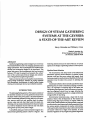
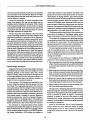
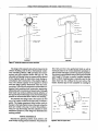
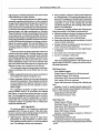
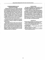
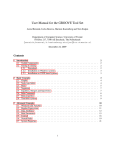
NOTICE CONCERNING COPYRIGHT
RESTRICTIONS
This document may contain copyrighted materials. These materials have
been made available for use in research, teaching, and private study, but
may not be used for any commercial purpose. Users may not otherwise
copy, reproduce, retransmit, distribute, publish, commercially exploit or
otherwise transfer any material.
The copyright law of the United States (Title 17, United States Code)
governs the making of photocopies or other reproductions of copyrighted
material.
Under certain conditions specified in the law, libraries and archives are
authorized to furnish a photocopy or other reproduction. One of these
specific conditions is that the photocopy or reproduction is not to be "used
for any purpose other than private study, scholarship, or research." If a
user makes a request for, or later uses, a photocopy or reproduction for
purposes in excess of "fair use," that user may be liable for copyright
infringement.
This institution reserves the right to refuse to accept a copying order if, in
its judgment, fulfillment of the order would involve violation of copyright
law.
Geothermal Resources Council, Monograph on The Geysers Geothermal Feld, Special Report No. 17,1991
DESIGN OF STEAM GATHERING
SYSTEMS AT THE GEYSERS:
A STATE-OF-THE-ART REVIEW
Harry Veizades and William J. Cain
VeiZades &Associates, Inc.
90 New Montgomery Street, Suite 707
San Francisco, Galifimia 94105
ABSTRACT
Geothermal gathering system designs have evolved at
The Geysers KGRA to meet ever changing operational and
design parameters. New technologies have enabled more
efficient and economical designs to be developed. This
paper lists some of the developments that have occurred
between 1973 and the present and presents the writers'
view of the current state-of-theart design and construction of the geothermal gathering facilities.
Topics covered are advances in pipeline route selection,
piping design techniques, selection of piping materials
and components, development of details, typical design
criteria and condensate removal and collection systems.
following sections discuss the state-of-the-art of various
aspects in the design of gathering systems at The Geysers.
Pipeline Route Selection
The mountainous and steep terrain of the Mayacmas
Mountains requires careful selection of pipeline routes
between wells and the power plants they supply. Such
factorsas access for construction and flexibility for thermal
expansion must be taken into account in selecting the
routing.
Condensatecollection lines normally parallel the steam
gathering lines. In order to minimize pumping of condensate, it is important to minimize sags in the steam and
condensatepipe alignment. Ideally, the steamand condensate line alignment should have no sags, allowing the
collection of condensate by gravity to a single condensate
storage facility for pumping.
Environmental constraints play a major role in route
selection. Most of the developments at The Geysers are
located along ridge tops and they are highly visible for
many miles. Careful selection of piping routes is required
to minimize the visual impact and noise transmission from
the various system components to nearby communities.
This is particularly important in areas where communities
are located within line of sight of the facilities. In some
areas the vegetation is very fragile and pipeline alignment
INTRODUCTION
The typical gathering system at The Geysers consists of
the facilities necessary to convey geothermal steam from
the steam wells to the power plant. It includes facilities to
collect condensate generated during start-up and operation, m o v e rocks and rock particles from the steam,
remove water and rock dust, inject water for steam conditioning, convey excess condensate from the power plant
to a well for reinjection into the reservoir and vent steam
during start-up and power plant outages.
A simplified piping and instrumentation diagram of a
typical steam gathering system is shown in Figure 1.The
285
Design of Steam GatheringSystems at The Geysess:A Statmf-the-Art Review
WELL SITE
r-----
I
VENT, TYPICAL
/
-CONDENSATE
POT
8 LIQUID DRAINER
TYPICAL
7
I’
SCRUB WATER
INJECTION
U
RUPTURE DISK
MUFFLER
\
WELL LINE ISOLATION VALVE
WELL LINE CONDENSATE COLLECTION
--
GATHERING SYSTEM COND COLL ECTlON
STEAM
GATHERING
____
____
---__
---\
CONDENSATE COLLECTION
BASIN
TYPICAL
I
I
I
ToELE(
.,...-
-Y
I
STEAM GATHERING SYSTEM DIAGRAM
WELL
WIRE LINE
VALVE
-
WORKING
VALVE
MASTER
VALVE --
WELL
///S//&/LW/L.Y/LZ/&
II
--
-
LINE CONDENSATE COLLECTION
T Y P I C A L W E L L LINE DIAGRAM
Figure 1. Simplified steam gathering piping and instrumentation diagram.
246
-1
~
TO CONDENSATE
COLLECTION BASIN
Harry Veizades and William J. Cam
model pipe restraints at pipe supports and gaps at the
guides and by iterative techniques provide an accurate
determination of piping behavior, pipe stress and pipe
movements. Several computer programs are available for
analyzing piping systems. Before any program is used,
however, the designer must determine whether the program accurately models the piping system and the pipe
supports.The proper modeling of incline supportsis very
important in selecting computer programs for analyzing
piping systems in the rough terrain at The Geysers.
The dynamic analysis capabilitiesof the computer p m
gram allow the designer to investigate system performance under seismic events and flow-induced vibrations.
The concepts for designing steam gathering pipelines
in mountainous terrain differ from piping designs within
the confines of a power plant. The typical power plant
piping is restrained to minimize loads on equipment nozzles. Expansion is accommodated by expansion joints.
The steam gathering piping outside the power plant,
with its meandering layout as it follows roads, trails,
ridges or topographic featuresis much more flexible and
can accommodate large thermal movements without becoming over stressed.
The concepts we have followed in designing piping
systems over the mountainous Geysers terrain are:
1.Take advantage of the flexibility that the piping layout
offers. Often the piping layout has sufficient flexibility
to accommodate expansion without the use of expansion loops.
2. Select supportsand anchors to provide maximum flexibility. Anchorsare spaced far apart (between500 to 700
feet) and located to control the pipe movements without reducing piping flexibility for thermal expansion.
3. Selectively restrain pipe for seismic and wind loads.
Such restraintsare selected so that they do not unduly
induce high support loads due to thermal expansion.
must be routed around these areas.Removal of vegetation
for construction must be minimized. Removal of vegetation creates barren areas that erode and produce run-ffinduced siltation of streams.
Access for construction is another important factor.
Many of the slopes in the area are very steep. One unpublished study (Veizades & Associates, 1981)of slopes
at The Geysers revealed that in an area of about 15 square
miles slopes exceeded two horizontal to one vertical over
75 percent of the area. Many of these slopes are covered
with highly fractured and hiable shale.
We have found that route selection is the most critical
aspect in the design process and should be assigned to an
experienced engineer. It is important that the engineer be
well versed in geothermal piping construction techniques, geotechnical evaluation, surveying,behavior of piping under thermal movements, condensate line hydraulics and environmental matters. Using maps produced by
aerial photography, several proposed alignments are studied on paper to determine the controlling parameters in
route selection. With these results in hand, the engineer
then performs a field reconnaissance of the most promising alignments. The final route selected is then marked for
clearing and right of way construction. Following right of
way construction, a precise survey of the proposed alignment is made. This survey provides the basis for preparation of construction drawings and for piping construction.
Piping Design Techniques
Lengqiust (1973)set forth somebasic design techniques
and details that have been used in the design of several
gathering systems at The Geysers. Since then, several
aspects of piping design have advanced through the use
of computer programs for flow and stress analyses. It is
now possible to make rapid, cost efficient analyses in a
matter of hours on a personal mmputer.
Flow analyses in The Geysers were traditionally done
by hand using the empirical Fritzche equation for pressure drops. For a large gathering system, this could become quite tedious when the designer wished to consider
multiple scenarios of flow. Today, computer based flow
analyses are performed using the Darcy-Weisbach formulation with steam properties automatically generated.
This process makes it possible to perform parametric
studies to examine how velocity and pressure change at
any desired point in the piping system. This enables the
designer to optimize the selection of pipe sizes and check
system performance under various steam flow scenarios.
The advances in computer-assisted stress analysis
techniques have enabled the designer to develop a much
better understanding of the behavior of piping systems.
Useof computer programs such as AUTOPIPE (Engineering Design Automation, 1987) enables the designer to
4. Design supports and anchors to restrain thermal, seis-
mic, wind, friction and thermal loads.
This approach in designing piping systems results in a
balanced design that minimizes stress and support loads.
Supports for steam gathering lines are typically constructed as a stanchion as shown in Figure 2. The bearing
assembly is welded in the field. This allows for final
horizontal and vertical adjustment of the pipe bearing
assembly to compensate for stanchion misalignments due
to construction tolerances.
Loads on the stanchions due to thwmd expansion,
friction, scismic and wind loads are resisted by lateral
bcaring against the soil or rock. Conservative loads for
dcsigning the supports arc used to produce a safe support
design.
247
Design ofSteam Cathering S y s t e m at The Geysers:A State-of-the-Art Review
E
no1
POSITION
TE
COLD POSITION
VENT
HOLE
\
1 PIPE STANCWION
I
I
I
I
I
CONCRETE
CAISSON
IN OWILLED HOLE
I
I
I
I
I
I
I
I
I
I
I
I
SUPPORT
ANCHOR
Figure 2. Typical pipe support and anchor stanchions.
HCI, H2S and C02 in the geothermal fluids as well as
chemicals added in the various abatement processes results in fluids with highly corrosiveto passive properties.
The primary piping material used at The Geysersis ASTM
A53, Grade B. The pipe is usually furnished seamless,
ERW or DSAW. Seamless pipe is normally used for the
steam lines from the wellhead to the root valve at the
header. Seamless pipe is less susceptible to cracking by
The design of the supports and anchors is based on the
Uniform Building Code (U.B.C.) (International Conference of Building Officials, 1988) provisions for nonconstrained pole type supports (Section 2907 (g) 2.A). The
dowable soil bearing values are conservatively selected
by the engineer based on observations made during reconnaissance after construction of the pipeline right-ofways. The ultimate capacity of the supports is several
times the design capacity detennined under the U.B.C.
provisions. This allows the supports to accommodate unexpected loads resulting from construction sequencing,
differential earth movements and impact loads.Although
these loads may produce additional lateral deflectionof
the supportsbeyond the design values, the flexible piping
systems can accommodate them without over stressing.
The standard shoe design used at The Geysers in 1973
was a "tee" section welded to the pipe with or without a
saddle. This design experienced some hairline cracks in
the pipe in the heat affected zones at the point where the
shoes are welded to the pipe. To correct this problem a
"strap on" type shoe design has been adapted on recent
installations (Figure 3). This design has eliminated the
cracking problem.
SADDLE
WEB
PLATE
PLATE
.GUSSET
B E A R I N G BAR
STANCHION
HOT
POSITION
4
4-
COLD
PO SlTlON
PIPING MATERIALS
Materials for gathering systems must perform well
under widely varying process conditions.The presence of
Figure 3. Strapon support shoe.
248
Harry Veizades and William J. Cain
Stress corrosion, cracking at welding neck flanges and
at welding fittings. This cracking manifests as a hairline crack. The presence of H2S and arseniccompounds
in the steam may contributeto this cracking.The actual
mechanism or cause of this cracking has not been
conclusively determined.This cracking,while costly to
repair, is not catastrophic.
To combat the cracking problems the following methods have applied in the design of piping systems:
Minimize welding on the pipe. Use strap-on shoesand
brackets rather than welding them to the pipe.
Preheat and post heat when welding flanges.
Stress relieve fabricated spools downstream of control
valves and other restrictions.
Increase thickness of piping material downstream of
control valves and other restrictions.
Avoid control valve settings that induce high fquency vibrations.
Use control valves with noise reduction times.
Use of low hydrogen welding rods.
high frequency vibrations produced by the control valves
orifice restrictionsand high velocities.
The use of carbon steel piping since the 1960shas been
successfulin geothermal steam service. A silica coating of
the pipe interior has protected the pipe from mmsion on
systems with relatively clean steam. Quite oftena corrosion allowanceisnot provided on such systems.Recently, however, some areas of The Geysers steam fields have
produced steam with high concentrations of chlorides.
These chlorideshave made a devastatingcorrosiveattack
on the steam lines. To combat this problem several methodshavebeenstudied.Amongthosearetheuseof more
exoticpiping materials,acceptanceof reduced use operating life with scheduled replacement of piping, and scrubbing of the corrosive agents. The most cost effective method of corrosion mitigation has been the installation of
scrubbing systems to remove or neutralize the corrosive
agents.
A recent innovationin piping construction is the use of
induction heat pipe instead of welding fittings for angle
changes in pipe systems. The induction bends minimize
field welding, expedite field installation,minimize radiographic inspection and reduce pipe stress due to lower
stress intensification factors. The use of induction bent
pipe with a bend radius from three to five times the pipe
diameter has been very successfuland cost effective.
The condensate transport piping systems handle geothermal condensate that can be divided into two categories:
1.Highly oxygenated fluids such as excess condensate at
the cooling tower slated for reinjection, and
2. Steam condensate collected for drip legs along steam
lines and from separators.This condensate is normally
hot and contains some dissolved solids and nonmndensable gases but has not been exposed to atmospheric oxygen.
The oxygenated condensate is highly corrosive and
piping materials used for its conveyance are stainless
steel, epoxy or cement lined carbon steel pipe or plastic
pipe. The nonoxygenated condensate is not as corrosive
and piping material used for transporting it is normally
carbon steel with a corrosion allowance. Pumps used in
condensate systems are specified with all wetted parts
made from stainless steel.
TYPICAL DESIGN CRITERIA
Most steam gathering systems at The Geysers are designed using the ANSI B31.1 piping code and the following design parameters:
Well Steam Lines:
(From wellhead to header)
Design Pressure:500 psig (full wellhead pressure)
Operating Pressure: 120 to 500 psig
Temperature: 490°F (Saturatedsteam temperature)*
Flow velocity: 250 ft/sec maximum
System Test Performance: 500 psig (full wellhead pressure)
Insulation: %inch for smaller diameter pipes and 4
inch for larger diameter pipes Fiberglass with density of
3 lbs/cu ft and aluminum jacketing.
Flange Rating: ANSI Class 300
Overpressure Protection: None
Gathering Lines
Design Pressure: 200 psig
Operating Pressure: 105 to 165 psig
Temperature: 340°F (Saturatedsteam temperature)*
Flow velocity: 50 to 250 ft/sec
System Test Pressure: 240 psig
Insulation: 4-inch Fiberglass w/density of 3 lbs/cu ft
and aluminumjacketing
Flange Rating: ANSI Class 150
Overpressure Protection:Rupture disks at 190 psig.
PIPE CRACKING
The piping systems at The Geysers have performed
extremely well in 30 years of service. There have been,
however,occasionswherecrackingofpipesoccurred.The
cracking can be attributed to the following:
High frequency vibrations induced by steam flows
downstream of orifice restrictions or control valves.
This cracking normally starts at a weld heat affected
zone. The cracking is sudden and catastrophic.
'When systems arry suprhtnted steam heoppiupriate temperutureshould
be usad.
249
Design of Steam Gathering Systems at The Geysers: A Stateof-&Art Review
CONDENSATE REMOVAL AND
COLLECTION SYSTEMS
Condensate generated in steam piping by heat losses
and during warm-up is collected in a seriesof condensate
drop pots (Freeston,1981)along the steam lines. Condensate is automatidly removed from the drop pots with
float controlled "liquid drainers."The use of various types
of steam traps has been unsuccessful.Presently, the Armstrong and Nicholson drainers are the only successful
devices for condensate removal. Collection lines, insofar
as possible, use gravity flow to convey the condensate to
a collection tank or sump from where it is pumped or
trucked to the cooling tower basin for reinjection.
The steam from wet wells is scrubbed to remove moistureby the use of separators. Condensateh m separators
is discharged by valving or drainers to the condensate
collecticm system.
Recent practice has been to inject water into the steam
upstream ofthe main separator to enhancethe separator's
abilityto remove particulatesand silica that are carried by
the steam. Careful control of this water injection has been
shown to reduce the amount of silica deposited on the
blades of the turbine. The condensate system is normally
designed to handle this additional load from the steam
scrubbing operations at the separators.
CONCLUSIONS
This paper has pmented a broad overview of the
developments in gathering system designs that have occurred since Lengqiust's landmark paper in 1973.
It should be noted that the design of geothermalgathering systems at The Geysers has been and continues to be
an evolutionary process. The designermust keep abreast
of the various operationaland performance problems and
develop piping designs to solve such problems. Communication between various operatorsand designerscontinues to advance the state-of-the art. Only by the close
cooperation and free flow of information between the
various operators and designers, can advancements be
made in the design of steam gathering systems.
REFERENCES
Engineering Design Automation, 1987. AUTOPIPE User's Manual,
Vesion 4.1. Engineering Design Automation, Berkeley,CA.
Freeston, D.H., 1981.Condensationpot design:Model tests,Geothermal ResourcesCouncil Transactions,vol. 5, p. 421.
International Conference of Building Officials, Uniform Building
Code, 1988edition.
Lengqiust, R. and Hamen, A.L., 1973. Geothermal steam piping at
Big Geysers, California, U.S.A., 1 W 7 5 .
Veizades and Associates,Inc, 1981. Slope map from unpublished
study for OccidentalGeothermal, Inc