1
PhoeniX Cleanroom Database
Process Flow Module
Application Note
200308001
Information management
for MST cleanroom processes
A systematic and efficient approach
in managing and preserving
the knowledge and expertise
in MST cleanroom environment
by using PhoeniX process flow module
Author: Sesilia Kriswandhi
Version 1
August 2003
1. Introduction..........................................................................................................................................2
2. The Hierarchy Of The Process Flow Database..................................................................................2
3. The Development Of The Process Flow Database............................................................................4
3.1 The Equipment..............................................................................................................................5
3.1.1 The References Menu...........................................................................................................6
3.2 The Process Steps.........................................................................................................................6
3.2.1 The Re-usable And The Specifically Defined Process Steps..............................................7
3.2.2 The Actions Menu.................................................................................................................8
3.3 The Process Blocks.......................................................................................................................8
3.4 The Process Flows........................................................................................................................9
3.4.1 The Summary And The Overview.......................................................................................9
3.5 The Control And The Result......................................................................................................11
3.5.1 The Control Menu In the Equipment ................................................................................11
3.5.2 The Control Menu In The Process Step.............................................................................12
3.5.3 The Control Menu In the Process Block
-- the inherited and the local controls --.....................................................................................12
3.5.4 The Control And The Result in the Process Flow
-- the mathematical expression to relate the control and the result -- ....................................13
4. The Process Validation In The Database..........................................................................................15
4.1 The Material Menu
-- the process validation at the equipment level -- .......................................................................15
4.2 The Relations Menu
-- the process validation at the step, block, and flow levels --.......................................................16
4.3 The Check Menu.........................................................................................................................16
5. The History
-- the quality improvement of the database -- .............................................................................17
5.1 The Commit, The Versions, And The Usage Menu.................................................................18
6. Conclusion..........................................................................................................................................19
Documentation of the cleanroom activities is required to preserve the knowledge about the processes and the
technologies involved; hence different users with different levels of expertise can obtain the relevant
information easily.
However, a documentation for the micro's and nano's cleanroom processes is difficult to realize because of
the diverse technologies involved1 .
The Process Flow Module in the PhoeniX Cleanroom Database is a tool to manage the documentation for
the micro's and nano's cleanroom processes. It offers the flexibility to implement various processes and
technologies affected. Nevertheless, its thoughtfully defined hierarchy and templates secure the
communication standardization.
When the database is managed correctly, the available processes is accessible considerably. Furthermore, the
quality improvement and most of the validation process will be automatically accomplished also.
PhoeniX ProcessFlowDB module can be extended to the OperatorDB module to incorporate the data's
digestion. The output data from the equipments can be registered as the input of the statistical process
control for design iterations by using the simlink. Scripts can perform the statistical process control, and also
can send an automatic warning message and email when a deviation is detected.
The purpose of this application note is to exemplify the development of an effective cleanroom database by
using the PhoeniX Process Flow Module. The focus of this note is not on the technological issues, but on the
documentation and the verification aspects.
The case study for this note, because of its well described technology, is the process flow of the optical core
SiON by using the PECVD and RIE processes.
! #"%$'&)(*&+-,+.$0/2143+"%$'&)567&'88:9.;<+= >%,-,.?,8@&
Assume that the people that are involved in the cleanroom activities can be grouped based on their major
expertise:
A
A
Equipment managers
Various equipments are available in the clean room, all with specific purposes and capabilities.
Equipment managers are the experts in the usage and the maintenance of these equipments. They also
give courses to use the equipments.
A
Operators
Operators are the executors of the process flows; which are typically made by the designers. The
operators are the experts in handling the wafers with the cleanroom's equipments. They ensure that the
process flows consist of the correct steps (which ideally are also reproducable).
Designers
Designers are the experts in the technology applications, designs and simulations. Since they focus on the
product optimization by the available technologies, they often have limited knowledge about the usage of
the cleanroom's equipments and the processes involved.
In reality, these functions are not always clearly distinguishable. These coarse function categorizations are
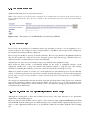
used as a reference to compose the hierarchy of the database.
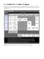
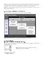
The Process Fow DB module in PhoeniX CR database consists of four levels of hiearchy, which are shortly
described at figure 2.1 below:
1Proceedings COMS 2003 “Trends in micro and nano software” by ir.N.Olij, ir.A.F.Bakker, dr.ir.H.H.van den
Vlekkert.
Figure 2.1 The hierarchy of the process flow database.
Each level of the hierarchy has a specific menu. Each menu contains unique templates. The menu and their
templates function as communication standard and knowledge management. This way the reuse, the quality
improvement, and the validation of the defined processes can be realized.
The usage of the menu/templates inside the hierarchy, and the definition of the processes to develop a SiON
optical core, will be briefly explained at section 3,4 and 5.
Section 3 will focus on the process development topic, while section 4 will bring up the issue about process
validation. The quality improvement will be mentioned at section 5.
BC#D%E'F)GHFJIKFLM NO:FKPQSR4T+D%E'F)U%VMWFXX:Y.L<M.Z G\[Q][+^[XF
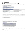
One important issue in developing a database is managing the information effectively. This section is
dedicated to show a possibility to sufficiently document the processes to develop an optical core by using the
SiON technology.
Figure 3.1 The menu/templates for process development in the Process Flow Database.
_a`cbedfhg4ij0kJl<mJnogqpsr
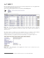
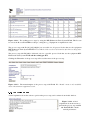
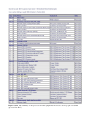
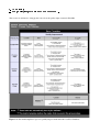
First the equipments that will be used in the processes should be defined. Below are some equipments that
are used for the etching and lithography processes.
The list of the available equipments can be seen at the ProcessFlowDB/Equipment.
Figure 3.1.1 List of some cleanroom equipments. The plus and the minus signs are used to arrange the
contents of each menu in alphabetical order. Here the contents of the “Category” menu are arranged in
alphabetical order .
The “Delete” buttons are available only for the equipments that are not committed yet. The committed
equipments cannot be deleted nor modified anymore, but one can still make a new version of it2.
Clicking the ID number of an equipment will enter the menu/template of the equipment (figure 3.1.2).
Figure 3.1.2
The menu/template of the equipment. The “Result” menu is dedicated only for the
measurement equipment.
2Refer to the online Manual for the elaborate explanation about how to use the PhoeniX database.
tvuxwyuxw{z|~}4'}}J}q
hv}~\}~
J
Additional information can be set as the references.
Note: The references in a form of the result files are recommended to be placed in the Process Step or
Process Block hierarchy, since they are related to the measurement processes instead of measurement
equipment.
Figure 3.1.1.1 The references for the RIE-Elektrotech Twin System PF340.
tauz|h}4'Jv}hv7}q
Process steps can be defined as a sufficient step-by-step description of how to use an equipment to do a
cleanroom process. For example: a step-by-step description to use RIE to etch a wafer are the venting step,
the vacuum step, and the parameter setting step.
Process steps are the key to develop an effective database. Process steps should be thoughtfully defined as
they are the constructors of the process flows. Adequate process steps will develop a database that is reusable and is able to validate the process flows automatically.
Adequate process steps are not necessarily a step-by-step manual of the equipment's usage.
Most cleanroom teams provide a well-defined manual for the usage of equipment. Besides, recent
equipments usually have a clear user manual with build-in software to help the user. The existing
information, including the result files, can be set as references inside the relevant process step.
What most cleanroom teams do not have are a well-defined and a self-validated process flow module that
can e.g. avoid the forgotten process steps /blocks; and this should be the purposes of anyone that designs the
process steps : the process steps should be re-usable and should be able to validate the process blocks/flows
that they build.
We strongly recommend that some time should be spent among all expertises in the cleanroom to make the
steps wisely and fairly complete, even if some may think “this will never be used”. The experiences show
that if an exception might exist, it will most likely occur sooner than later. Being prepared for this will save
considerable effort in the future.
tvuhucwz'|h}4'}vJ}H
hz'|h} .h}vh¡¢£¡a~¤¦¥#§'}£¡
h}v'Jv}~v}q
Although one would prefer to have the re-usable process steps, some steps may have to be specifically
defined due to the specific purpose.
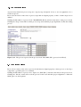
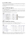
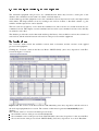
Below are the list of the available process steps to etch a wafer by using equipment RIE-Elektrotech Twin
System PF340. Several etching gases for different purposes are available in this equipment. Dus the process
step to set the equipment parameters has to be specifically defined in accordance with the chosen etching
gas.
Figure 3.2.1.1 The etching process steps by using the RIE-Elektrotech Twin System PF340. This list can
be seen at the ProcessFlowDB/ProcessSteps, sorting the e.g. “Equipment” in alphabetical order.
The process steps with ID [81],[91],[80],[92] are accessible for all process blocks that use the equipment
RIE-Elektrotech Twin System PF340. Process Block is the next level of hierarchy after Process Step (refer
to figure 3.1).
The process step with ID [90] is dedicated only for a specific process block that use the equipment RIEElektrotech Twin System PF340 and the etching gas SF6.
Clicking the ID number of the process step will reveal the menu of the process step.
Figure 3.2.1.2 The menu/template of the process step with ID 90. The “Result” menu is only available
when a measurement equipment is used.
¨v©ª~©ª«¬h®¯°²±³´µ¶\q´·
A brief explanation about the actions to perform the process step can be written down in this window.
Figure 3.2.2.1 A brief
explanation about the actions to
perform the process step with ID
90 “Etch,RIE,SF6, check/
set/read parameters”.
¸a¹¸»º¼h½4¾'¿ÀJÁv½hÂvÂÃ+ÄÀJÁqÅÂ
As previously mentioned, process steps are a step-by-step description of how to use an equipment to do a
cleanroom process.
Process block consists of the series of process steps that are aligned properly so that a cleanroom process is
defined.
Clicking the ID number of process block “Etch,RIE,SF6 (ID 36) will show the menu of the process block.
Clicking the “Steps” menu will reveal the process steps used and their proper alignment to define the etching
process.
Figure 3.3.1 The process steps used in the process block “Etch, RIE, SF6” (process block ID 35).
¸v¹ÇÆȺ'¼h½É¾'¿ÀJÁv½hÂvÂÊ~ÄÀJËÌÂ
Process flow consists of the series of process blocks that are aligned properly so that a process to develop a
component; e.g. SiON optic core; is defined.
Clicking the ID number of process flow “Optic core SiON (ID 7) will show the menu of the process flow.
Clicking the “Blocks” menu will reveal the process blocks used and their proper alignment to define the
SiON optic core development.
Figure 3.4.1 The process blocks used in the process flow to develop optic core SiON (process flow ID 7).
ÍvÎÇÏJÎxÐeÑÒhÓ ÔKÕÖ×Ö ØÙÛÚ*Ü\Ý~ÞÑÒhÓàßáhÓJÙÛáJâÓã
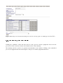
Clicking the “Summary” menu will show the list of the processes and the equipments involved in the
process flow. The “Overview” menu is the detailed version of the summary.
The summary and the overview are generated automatically by the database. Clicking on the underlined
process and equipment will enter the templates of the process and the equipment themselves.
Figure 3.4.1.1 The summary of the processes and the equipments involved to develop optic core SiON
(process flow ID 7).
ävåxæèçéhêàëíìîsï-ðì0ñóò\îhôÉçéhê4õê~öa÷Jñï
The control and the result are the links among the processes defined in different levels of hierarchy. They
communicate by using the mathematical expression, e.g. the result in the process flow level is a function of
the controls in the process blocks or in the equipments.
The available mathematical functions and expressions for ProcessFlowDB are listed in the Online Manual of
PhoeniX Database.
ävåxæyåxø{çé~êàëSìîhï-ðì0ñ~ù\êqî÷4ú<î ï£éhê4ûü0÷Jý<þJÿê~îsï
The control buttons of the equipment should be defined completely, so that they can be used in various
process steps and process blocks.
For example, the RIE-Elektrotech Twin System PF340 has several gases to etch the wafer. All the available
gases have to be defined in the ProcessFlowDB/Equipment level. Further in the higher hierarchy
(ProcessFlowDB/ProcessSteps or ProcessFlowDB/ProcessBlocks), the specific gas(es) used to etch can be
assigned depends on the relevant process.
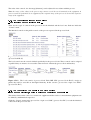
Clicking the “Control” menu will reveal the controls of the equipment.
Figure 3.5.1.1 The controls of
RIE-Elektrotech Twin System
PF340 (equipment ID 33).
ävåxæyå çé~êàëSìîhï-ðì0ñ~ù\êqî÷4ú<îàçéhê 'ðì vê~öaö 7ïêqþ
The controls of the process step are the controls of the equipment used by that process step.
At this level, we assign which controls of the equipment are relevant to the process step.
The relevant controls are assigned as public so they can be used in the higher hierarchy.
Figure 3.5.2.1 Assign the controls for the process step “Etch,RIE,SF6,check/set/read parameters” (process
step ID 90). The controls assigned as public will be used in the higher hierarchy; in this case the process
block that define the etching process by using gas SF6 (process block ID 35 – figure 3.5.3.1 below).
The value of the controls, also the range [min,max], can be adjusted in accordance with the process.
Note: the range of the values in the process step cannot exceed the one determined in the equipment. A
process cannot be performed by an equipment if the required range of the process is beyond the capacity's
range of the equipment.
!"#$&%(')*+,-.
0/1/324.$5
676
+38)0&98:
;=<&;+3.1<$>.
!/
676
There are two types of controls in the process block: the inherited and the local ones. Both are inside the
“Control” menu.
The inherited controls are the public controls of the process steps used in the process block.
Figure 3.5.3.1 The inherited controls from each proces steps used in the process block “Etch, RIE, SF6”
(process block ID 35)
The local controls are the controls defined specifically for the process block. These controls can be assigned
as public if they are meant to be accessible at the next level of hierarchy (process flow and batches).
Figure 3.5.3.2 The local controls of process block “Etch, RIE, SF6” (process block ID 35). Assign as
public, they will be accessible at the higher hierarchy, in this case the process flow “Optic core SiON”
(process flow ID 7).
@?A!CBD;=EF/
%:G8)H+,-7I.10/
/3J0&K
676
+MLN<1+$LN<
98.1<0OPQ0/1/
8G*R0:<
S+.
!T<&;+70/
%:
676
The relation between the control of a cleanroom equipment and the result of a measurement equipment can
be defined by mathematical expression.
Click the “Control” menu in the process flow “Optic core SiON” (process flow ID 7) reveals the inherited
controls from the process blocks.
Figure 3.5.4.1 The inherited control from process block “Etch, RIE, SF6” (process block ID 35).
Note: the local controls of the process flow will become the inherited controls of the batches.
The process flow “Optic core SiON” uses a measurement equipment (Dektak) to measure the etch depth.
Click the “Result” menu shows the results of the process flow “Optic core SiON” (process flow ID 7).
Figure 3.5.4.2 The results of the process flow “Optic core SiON” (process flow ID 7).
The etch depth, together with the duration time of the etching process, are used to obtain the etch. The etch
rate is the etch depth devided by the duration time of the etching proces
Click the magnifying glass beside the “Expectation” value of “Etching rate” reveals the mathematical
expressions used to define the relation between the flow result and the block control.
Figure 3.5.4.3 The mathematical expression to define the etch rate as the etch depth (process flow result
with ID 18 – refer to the “ID” at figure 3.5.4.2 ) devided by the etcing's duration time (process block control
number 6 with ID 42 – refer to the “FStep” and “ID” at figure 3.5.4.1).
The mathematical expressions to define the minimum and the maximum values of the etch rate are obtained
in the similar way, replacing the “value” with “minvalue” and “maxvalue” respectively, e.g.
processflowresults[18].minvalue/processblockcontrols[6][42].minvalue.
The mathematical expressions are able to interconnect the controls and the results from different levels of
the hierarchy. The higher level controls can be used to specify the lower level controls. The results of the
current level can be used to specify the consecutive controls, and also the results in the higher level.
Thus the process flow controls can be used to set the controls of the first block in the flow. The controls and
the results of the first block can be used for the second block in the flow. The flow results can be a
combination of the controls and results of the applied blocks, and also its own controls naturally.
NOTE: The available mathematical functions and expressions for ProcessFlowDB are listed in the Online
Manual of PhoeniX Database.
U4VXWZY-[]\_^a`cb[FddXegfihkj)l4fGmnjo`qpsrptW_Y-[]u_fGmvf4wGfidI[
This section is dedicated to bring up the issue about process validation in FlowDB.
Figure 4.1 The menu/templates for process validation in the Process Flow Database.
xyz|{}0~_1~9:$#~$
&
7
+}0~MQ7I1~0
#$&
9
*
+}0~S~
!I)3~0
~0~
7
The process validation in the database can be started at the equipment level by defining the available and the
forbidden materials for the equipment.
Figure 4.1.1 The available and the forbidden materials for the
RIE - Elektrotech Twin System PF340.
0-0:
9&3 #$&¡
¢7¢
+M£Q¤¥
#¦$§&
9N
+3>0£&¨©&I¥0ª1¨T&§=«+&¬¦0
¢7¢
At the processes level, the validation is defined inside the “Relations” menu. Below, as an example, the
relation among the process steps are established: which steps are allowed and which ones are not allowed
after and before a process step respectively.
Figure 4.2.1
The required preceding step and the forbidden proceeding steps for the process step
“Etch,RIE,SF6,check/ set/read parameters” (ID 90).
Note: the re-enabled proceeding steps are used when the forbidden proceeding steps can be applied after a
certain preliminary steps. For example: KOH etching should never proceed RIE, except when the cleaning
steps are performed beforehand. So at the cleaning step, which should be set after the RIE step, select the
KOH etching in the box “The re-enabled proceeding steps”.
Specifically defined preceding and proceeding steps can avoid the confusion in the alignment of the process
steps to perform a cleanroom process.
®¯±°²0³´q²³
µ$¶N·#³0¸¹
This menu checks the materials used and the alignment of the process steps used in the process block.
This action will be automatically done by the database only if the process validations at the equipment level
and the process step level were defined (refer to sections 4.1 and 4.2).
Figure 4.3.1 Warning message when the process steps are alligned incorrectly, e.g. when the step “etching
process” is set before the step “minimize reflected RF power”.
The messages at figure 4.3.1 suggest that the step “minimize reflected RF power” should precede the step
“etching process” , and the step “check/set/read parameters” should precede the step “minimize reflected RF
power”.
When the steps are alligned correctly, there will be no message.
ºI»½¼_¾-¿]ÀSÁÃÂIÄÅÇÆ9È
ÉÉ
Äʾ-¿ÌËÎÍ-ÏiÐkÁÄ9ÈÑÁkÒÑÓÔÆaÅFÕF¿ÖÒ׿ÖØÄÔÅÖÙÔÄʾ-¿ÌÚ4ÏÄvÏ4ÛÏFÂI¿
ÉvÉ
This section is dedicated to bring up the issue about the quality improvement in FlowDB.
Figure 5.1 The menu/templates for process quality improvement in the Process Flow Database.
ÜÝÞàßáâãäååæ:ç9èTßáâêéÖâëíì
æäGî&ì
èCïDîðMß-áâ=ñ4ì>òóâô#â$î&õ
The well-built equipment and processes are committed/saved hence they become a static part of the
database; the committed versions cannot be edited or deleted anymore.
As the technology and the equipment evolve, the committed versions may however need some improvement
in the future. The improvement is done by creating a new version of them, so that their contents, e.g. the
variables and the expressions, can be adjusted.
The new version is assigned to evolve from the committed one, but it can also be created from the not-yetcommitted version. This implies several committed and several not-yet-committed versions exist, and they
are related to each other.
The database provides the service that tracks and keeps the history of the available versions, the evolution of
each version, and the relation between each version of the processes and the equipment.
ö-÷øêùÖø&ú9û
üýþ&û3ÿ#ø$þ
The “Versions” menu reveals the available versions, their evolvement, and the versions of the applied
processes and equipment.
Clicking the “Versions” menu in the Process Block “LPCVD SixNy (stress free) deposition” with ID 1
reveals the figure 5.1.1 below:
Figure 5.1.1 The versions of the Process Block “LPCVD SixNy (stress free) deposition” and the version of
the used steps/equipments/cross-section. The contents of this menu is generated automatically by the
database.
The contents of the box “Versions from this process block” :
the available versions of the process block with their ID
the committed version of the process block “LPCVD SixNy (stress free) deposition” is the one with ID 1.
the second version of the process block “LPCVD SixNy (stress free) deposition” is evolved “BasedOn”
the version with ID 1.
the “MostRecent” committed version is the version with ID 1.
NOTE: The most recent version is not always the same with the latest one. The database refers the most
recent version to the latest committed version, which is not necessarily the latest version of the processes.
Attention should be paid on the revision timeline, which is fully described in the online Manual of PhoeniX
ProcessFlowDB.
The “Usage” menu reveals the application of a version in the ProcessFlowDB hierarchy.
Clicking the “Usage” menu in the Equipment “Balance” with ID 6 reveals the figure 5.1.2 below:
Figure 5.1.2 The application of the first version of the Equipment “Balance” with ID 6 in the Process
FlowDB hierarchy. The contents of this menu is generated automatically by the database.
NOTE : The “Usage” and the “Version” menu are available in each level of the process flow hierarchy
(refer to figure 5.1 ).
"!#%$'&(*)+"!
The Process Flow Module in the PhoeniX Clean Room Database is a tool to manage the documentation for
the micro's and nano's cleanroom processes. It offers the flexibility but also the communication
standardization to the various processes and technologies involved.
A properly managed database guarantees the accessibility of the available processes in the hierarchy. Also,
most of the validation process will be able to be done automatically so that the confusion in the process
alignment and the equipment contamination can be prevented. Finally, the regular update and maintenance
of the database will secure the continuous improvement of its quality.