1
Loma Systems
Axis Series X-Ray Inspection Systems
Conveyor and Pipeline Models Software Version AXIS X3
Loma Axis X3 User Manual
Part No 814130, Issue Level C
CONTENTS
1
The Loma Group Companies & Service Centres
2
Cautionary Advice
3
Radiation Surveys
4
Principles of Inspection
5
Installation
6
Product Descriptions
7
Operators Guide and setup
8
Maintenance
9
Wiring Schematics & Certificate of Conformity
10
Parts Listing & Software Licence
Module 0000
The Loma Group Companies & Service Centres
THE LOMA GROUP OF COMPANIES
UK
Loma Systems Limited, Southwood, Farnborough, Hampshire, GU14 0NY, England
Telephone:
01252 893300
Fax:
01252 513322
CANADA
Loma Canada Limited, 333 Wyecroft Road, Unit 11, Oakville, Ontario, Canada L6K 2H2.
Telephone:
1-800-387-7987
Fax:
905-842-3460
905-842-4581
NETHERLANDS
Loma Systems BV, Panovenweg 22, 5708 HR, Helmond, Netherlands.
Telephone:
0492 573573
Fax:
0492 573570
USA
Loma International Inc., 283 East Lies Road, Carol Stream, Illinois 60188, USA.
Telephone:
Module 1000
1-630-588-0900
Fax:
1-630-588-1395
1-800-USA-LOMA
Internet address: WWW.LOMA.COM
The Loma Group Companies & Service Centres
THE LOMA GROUP SERVICE CENTRES
UK
Loma Customer Services Dept., Unit 43 Campus Road, Bradford, West Yorkshire BD7
1HR
Telephone:
01274 378200
Fax:
01274 729716
MAINLAND EUROPE
Loma Systems BV, Panovenweg 22, 5708 HR, Helmond, Netherlands.
Telephone:
0492 573573
Fax:
0492 573570
USA and SOUTH AMERICA
Loma International Inc., 283 East Lies Road, Carol Stream, Illinois 60188, USA.
Telephone:
1-800-USA-LOMA / 1-630-588-0900
Fax:
1-630-588-1396
CANADA
Loma Canada Limited, 333 Wyecroft Road, Unit 11, Oakville, Ontario, Canada L6K 2H2
Telephone:
1-800-387-7987 / 905- 842-4581
Fax:
905-842-3460
REST OF WORLD
Loma Customer Services Dept., Unit 43 Campus Road, Bradford, West Yorkshire BD7
1HR, UK
Telephone:
Module 1000
(44) 01274 378200
Fax:
(44) 01274 729716
Cautionary Advice
CAUTIONARY ADVICE
CONTENTS
Safety Warnings
Local Rules (UK Example)
Emergency Shutdown
Dealing with Fire
Audible Warnings
Visual Indications
Radiation Levels
O.S.H.A. Warning
Due Diligence
Module 2000
Cautionary Advice
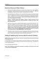
Safety Warnings
Listed below are all the safety warnings that are used throughout this manual. It is strongly
recommended that personnel who are, or will be, responsible for installing, maintaining or
operating the equipment described in this manual should read and understand these
warnings.
1.
LETHAL HAZARD – ELECTRICAL SUPPLIES. A current of 100 milli-amps passing
through the body for one second can kill. This can occur at voltages as low as 35V
ac or 50V dc. The equipment described in this manual uses electrical power which
can be lethal. Unless absolutely necessary, cleaning, inspection and maintenance
must not be carried out without first isolating the equipment from all electrical
supplies.
2.
LETHAL HAZARD – RADIATION. Whilst every precaution has been taken to make
sure that all the necessary guards and safety devices have been fitted to the Loma xray unit, it is recommended that all operatives are trained in the use of x-ray food
inspection machines. Furthermore it is the responsibility of the employer to create a
set of local rules (see example at the end of this section) regarding the safe use of xray food inspection systems. In the U.K. this is in compliance with the Ionising
Radiation’s Regulations 1999, users outside of the UK should consult the relevant
health and safety executive (see also Radiation Surveys in this manual).
3.
LETHAL HAZARD – COMPRESSED AIR SUPPLIES. The equipment described in
this manual may be supplied with a compressed air supply operating at a pressure,
which may be lethal. Unless absolutely necessary, cleaning, inspection and
maintenance must not be carried out without first isolating the equipment from all
compressed air supplies. In addition, it should be checked that all air pipes are
properly connected.
4.
WORKING ON EQUIPMENT. If it is essential to work on the equipment with
electrical and/or compressed air power connected, the work must be undertaken only
by suitably qualified and authorised personnel who are fully aware of the danger
involved and who have taken adequate safety precautions to avoid contact with
dangerous voltages, radiation (see Radiation Surveys) or compressed air supplies.
5.
REJECT DEVICES. At no time, with compressed air and/or electrical power applied
to an automatic reject device, should any part of the body be placed within the
operating area of the reject device. In addition no attempt should be made to operate
the AXIS x-ray machine without the reject bin or guards in place.
6.
EXCESSIVE NOISE. When an air blast reject device operates, the noise emitted
may constitute a noise hazard. While short exposure to this noise will not
normally cause permanent damage to hearing, prolonged exposure may cause
some damage. It is recommended that ear defenders are worn by personnel
who are regularly exposed to the noise.
Module 2000
Cautionary Advice
7.
HEAVY EQUIPMENT. The equipment described in this manual is extremely heavy
and considerable care must be taken when handling it. Sufficient personnel and a
suitable forklift truck or pallet truck must be used to ensure safe handling. In addition
attention should be paid to the Axis Lifting Points drawing in the Installation section of
this manual.
8.
LIFTING EQUIPMENT. Use only the correct slings and lifting tackle to move heavy
items of equipment described in this manual. Inspect all slings and lifting tackle prior
to lifting the equipment to ensure that:
9.
a)
The safe working load will not be exceeded.
b)
There are no frayed or broken strands.
c)
Hooks, rings, etc. are not damaged.
MOVING THE MACHINE. The centre-of-gravity of the conveyor is high. Care must
be taken when moving such equipment on a slope to ensure that it does not topple
over. This could result in death or severe injury to an individual and/or severe
damage to the machine (refer to Axis Lifting Points in the Installation section of this
manual).
10. CONTAMINANTS. Oils and greases must always be handled with care. Prolonged
bare skin exposure to certain oils and greases can cause skin problems. Always
handle oils and greases in accordance with the manufacturer's instructions (for types
used see section on routine maintenance).
11. TRAPPED FINGERS. Do not place fingers on the underside of the x-ray conveyor
belt when the machine is operating. It is possible for fingers to be trapped and
subsequently crushed between a moving and fixed component of the machine.
Trapped fingers is also to be avoided during pipeline normalisation.
12. WARNING LABELS. The Loma AXIS x-ray machine has a number of warning labels
and engravings throughout the system. Particular attention should be paid to the
location of these warnings and their significance in operating the machine safely. If
necessary because of local requirements some labelling may also be provided in a
second language.
13. GUARDS. No machine is to be run without guards fitted unless for maintenance
purposes and only if adequate precautions have been taken.
Under no
circumstances is any interlock to be defeated. This could lead to serious leakage of
radiation if operated with x-rays on in such a manner.
14. PIPELINE NORMALISATION. Care is to be taken when carrying this out to ensure
correct posture and no over exertion is made.
Module 2000
Cautionary Advice
Local Rules (UK Example)
Ionising Radiations Regulations 1999 Local rules
1.
GENERAL
These rules are provided in compliance with the Ionising Radiations Regulations 1999
(IRR99) (Regulation 17) and the Associated Approved Code of Practice - "Work with
Ionising Radiation".
The rules are the general principles and description of the means of complying with the
Regulations and should be seen as implementing part of the general safety policy
required by Section 2 of the Health and Safety at Work etc. Act 1974.
Aims: to ensure that work with ionising radiations is controlled so that:
2.
1)
During normal working, radiation doses to all persons are as low as
reasonably practicable,
2)
Precautions have been taken to minimise the risk of equipment failure or other
occurrence which may result in significant radiation doses to any person, and
3)
No doses exceed those specified in the Regulations.
RADIATION PROTECTION SUPERVISOR (RPS)
[INSERT NAME OF RPS]
The RPS is responsible for ensuring the work is carried out in accordance with
requirements of the regulations and for taking all reasonable steps to ensure that these
rules are observed. In addition, the RPS should carry out a radiation dose rate survey
of the unit at least once a month or after maintenance. Checks should also be made
on the operation of any warning lights and door interlocks. A record should be kept of
the monitoring results (dose rates should be noted in units of “µSv/h“) and safety
system checks.
3.
AUTHORISED STAFF
Only staff who have been trained in the use of the x-ray unit may operate the
equipment. The staff authorised to use the equipment are listed below.
[INSERT NAMES]
4.
DESIGNATION OF AREAS
No controlled or supervised areas require to be designated in connection with this unit.
Module 2000
Cautionary Advice
5.
GENERAL PRECAUTIONS
5.1
Any failure of a warning light or interlocks must be reported to the RPS as soon as
possible. In the event of a fault resulting in the failure of the door interlock or shielding,
the equipment must not be used until it has been repaired. A notice stating that the
unit is out of use must be displayed on the unit.
5.2
Before generating any x-rays, check that the warning lights are functioning.
5.3
Before accessing the interior of the unit, e.g. for cleaning, check that the unit is
disconnected from the power supply.
5.4
Do not tamper with or attempt to over-ride the door interlock – this could result in
exposure to the primary x-ray beam.
5.5
When the equipment is not in use, remove the key to prevent unauthorised use.
6.
MAINTENANCE
Maintenance will be carried out by appropriately qualified service engineers when
necessary. No attempt should be made to repair the x-ray unit without advice from a
qualified service engineer.
After maintenance, the unit should be monitored using a suitably calibrated radiation
instrument and a record kept of the monitoring results.
7.
RISK/ HAZARD ASSESSMENT
Potential hazards are:
7.1
Failure of an interlock resulting in generation of x-rays while the cabinet door is open.
7.2
Radiation leakage from the cabinet as a result of misplaced shielding following repairs
to the unit or non-operation of an interlock. Routine monitoring around the unit
following repairs or maintenance should minimise this risk.
7.3
Fire or mechanical damage which may effect the integrity of the shielding.
Under normal operating conditions, the equipment is adequately shielded and doses to
operators will be low (< 50 “µSv per year).
8.
CONTINGENCY PLANS
IMMEDIATE ACTION is necessary to prevent exposure of persons to radiation.
8.1
In the event of a fault, SWITCH OFF the equipment and remove the key from the
switch.
8.2
Do not use the equipment again until the fault has been rectified and the absence of
any radiation leakage is verified.
8.3
Notify the RPS of the fault.
8.4
In the event that it is suspected that a person has received an over exposure then the
RPS must be contacted immediately.
Under these circumstances, the RPS must ascertain if a person has been exposed and
the magnitude of the exposure. If investigations determine that an over-exposure has
taken place then the Health and Safety Executive must be notified of this forthwith.
Module 2000
Cautionary Advice
Emergency Shutdown of X-Ray System
Each x-ray system manufactured by Loma Systems is fitted with emergency ‘Stop’
buttons. These are mounted on the front and sides of the control panel and at the rear
of the machine. In the case of a pipeline machine, due to the size and no conveyor
present only two emergency stops are required and are situated on the front control
panel and the rear door. The buttons are red in colour with a yellow background. In the
event of an emergency, which requires the conveyor to be immediately stopped, press
the stop button and both x-rays and the conveyor will be stopped.
Dealing With Fire
In the unlikely event of fire occurring in an item of equipment manufactured by Loma
Systems, it is important that a fire extinguisher containing the correct type of
extinguishing material is used. Fire on electrical equipment must be extinguished using
either a dry powder or carbon dioxide (CO2) extinguisher.
Audible Warnings
The AXIS x-ray machine is fitted with an alarm, which operates in the event of a fault
condition. The maximum volume of the alarm is 116 dB(A) and is adjustable via a
potentiometer on the back of the alarm itself.
Visual Indications
The AXIS x-ray machine is fitted with indicator lamps, which operate to show a
particular status or in the event of a fault condition. The machine must not be operated
unless all such indicators are fully operational.
Radiation Levels
Each Loma x-ray inspection machine has a critical examination to ensure that the
radiation levels emitted from the system are within the specified allowable limits. In fact
at Loma we strive to be well inside the allowable limit to maximise confidence in a safe
system. The legislative figure in the UK is 1µ Sv / hour but on the AXIS machine we
generally achieve 0.1µSv / hour on average.
In addition when a system is commissioned on a customers premises another critical
examination is carried out and the results stored on record at Loma. A copy of which is
also provided to the customer (see Radiation Surveys).
Module 2000
Cautionary Advice
Occupational Safety and Health Administration Warning
“In the United States of America, the Occupational Safety and Health Administration
(O.S.H.A.) Acts quite clearly place the burden of compliance on the user of equipment,
and the acts are generalised to the extent that determination of adequacy of
compliance is a judgement decision on the part of the local inspector. Hence Loma
cannot be held responsible for meeting full requirements of O.S.H.A. or O.H.S.A. with
regards to any equipment supplied, nor can Loma be held liable for penalty which may
be assessed for failure to meet the requirements of the acts as interpreted by an
authorised inspector. Loma, however, does act in a responsible manner with regard to
safe design of equipment and will always work with customers to assist where possible
in the remedy of any violations at a reasonable cost to the buyer.”
Module 2000
Cautionary Advice
Advice On Due Diligence
By your selection of a Loma x-ray system you have demonstrated your intention to assure
the quality of your products and thereby protect your customers.
The following six simple actions will help you maintain Due Diligence:
1.
Once your Loma x-ray system is installed you should contact your local Loma Service
Department to have the system commissioned.
2.
Check on a daily basis the radiation levels around the x-ray system (<1µSv/hr) using
a suitable radiation meter (Details available from Loma Systems Limited) and record
the results (see Radiation Surveys).
2.
Regularly check the operation of the x-ray unit (once an hour is recommended).
Keep accurate records of those tests and the contaminant samples being used, along
with the product details.
3.
If the x-ray test fails the test, quarantine the product from the last test and reintroduce through the x-ray unit once the equipment is fit for use.
4.
Have the equipment supported by a Planned Preventative Maintenance Contract.
Details can be obtained from your local Loma Service Department.
5.
If you have or intend to have BS EN ISO 9000 accreditation, write a section into your
Operating Procedures Manual covering x-ray test procedures and have each x-ray
radiation meter regularly calibrated with a certificate issued.
6.
Finally, at least on a yearly basis, have your operators, QA and maintenance
personnel trained in the use of the equipment. Details of available training can be
obtained from your local Loma Service Department.
Module 2000
Radiation Surveys
RADIATION SURVEYS
CONTENTS
Introduction
Radiation Exam
Interlocks and Emergency Stop Switches
Radiation Dose Rates
Routine Operational Testing
External Radiation
Measuring Dose Rate
Frequency of Monitoring
Summary of Test Procedures
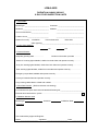
Example Survey Report and Form
Module 3000
Radiation Surveys
Introduction
As with all x-ray machines the LOMA AXIS produces ionising radiation when x-rays are being
generated. However, legislation governs the allowable emission levels and safe working
practices when using a x-ray machine. With this in mind the AXIS machine has been
designed to provide adequate shielding throughout the system, with safety interlocks
preventing the guards or access panels from being lifted or removed without x-ray generation
being stopped. However, it is recommended, and may be required by your country, state or
province, to document a radiation survey of the AXIS machine on the following occasions.
1)
Daily.
2)
After any maintenance has been performed.
3)
After the machine has been moved for any reason (new location etc).
3)
After any damage has occurred to the system.
4)
As per the regulations of your country, state or province.
A documented survey program assures the system is performing correctly, has not been
damaged and provides regular data that the system meets all radiation guidelines.
Note: When your AXIS system is commissioned your Loma service engineer will carry
out an initial survey report and provide you with a copy. The UK regulations also require
that radiological information is provided. This information is given in the Cautionary
advice section under Local Rules.
Radiation Exam
To ensure that maintenance, modification, damage, or distortion of the cabinet, and cowlings
etc. do not result in any deterioration of the safety system it is important that regular checks
are carried out.
Module 3000
Radiation Surveys
Interlocks and Emergency Stop Switches
Lids that may need to be opened by operating staff in order to clear obstructions etc. are
interlocked to prevent x-rays being generated while the lid is open. Service panels that only
need to be opened by trained service personnel are similarly interlocked. The interlocks
used are either tongue or magnetic type safety switches, which via safety relays trip the high
voltage power supply and stop x-ray generation. The switch is fixed to the frame of the
machine and a protective panel, when properly seated, closes the switch. After the high
voltage power supply has been tripped it is necessary to re-start the inspection in order to
generate x-rays.
The emergency stop switches act in a similar manner to the interlocks. After actuating any
emergency stop it has to be manually reset before the x-ray generator can be restarted.
Radiation Dose Rates
In most if not all countries where ionising radiation is used there will be a maximum allowable
emitted dose rate per hour. In addition, the dose measurement must be recorded at a set
distance from the machine surface and around the machine at any aperture or discharge
conveyor points.
In order to check that the emitted radiation level is within the guidelines a suitable radiation
monitor must be used which is regularly calibrated at least once a year.
Please contact your Loma Customer Service office for details on obtaining the correct type of
radiation monitor.
Routine Operational Testing
After the x-ray inspection system has been installed the service engineer will carry out a full
radiation and safety survey of the x-ray system.
For assurance that the system remains safe both the emergency shut down system and
measurement of the surface dose rates need to be included in a regular test schedule.
The emergency stops provide the means for the operational staff to shut down the system
rapidly. Although the stops provided are of proven reliability, it is important that they are
tested on a frequent basis.
The test consists of actuating each stop individually while the x-ray generator is operating
and noting that the system immediately shuts down. It is also a requirement that when the
stop has been manually reset the system does not automatically start up.
The conveyor covers need to be opened to clear blockages, etc. on the conveyor belt and it
is important that the safety interlocks immediately shut down the system.
Opening each lid in turn and noting that the system immediately shuts down tests the
interlocks. As noted above the system needs to be re-started before x-rays can be
generated again.
Module 3000
Radiation Surveys
External Radiation
Changes in radiation dose rate, either at the surface of the machine or at the infeed and
outfeed ports, is most likely to be noted following any material alterations to the system such
as a change in the arrangement of the conveyor or lids etc. In addition, if the x-ray tubes
operating voltage is raised or lowered, this will affect the reading measured. It is therefore
important that a full radiation survey should be carried out following servicing or repair work.
Otherwise changes in the dose rate at the surface of the machine in general are unlikely to
be noticed.
If changes are observed it will be at either the infeed or the outfeed ports because it is here
that product enters and leaves the inspection chamber allowing some x-rays to scatter along
the conveyor belt. In view of this the ports are the most important places for routine
operational monitoring, but all surfaces should be checked as well.
Frequency of Monitoring
As noted above the most sensitive area for changes in the dose rate are the ports and as a
consequence these should be monitored most frequently. To measure the dose rate at the
two ports will take only a few minutes and should be carried out either once per day or once
per shift as appropriate.
It is recommended that the dose rate at the ports be measured at the start of each shift or
day so that each operating team can feel confident that all is well when they start work. The
results should be noted in some form of record so that any longer term trends can be
observed.
Radiation shielding of the main beam and elsewhere in the console is intrinsic to the design
and where additional shielding is fitted it is mechanically fixed by welding or bolting. As a
consequence of this it is reasonable to assume that there will be no changes in dose rates at
the surfaces of the machine etc., and routine monitoring of these may therefore be less
frequent. In addition to this a full survey should be made following any maintenance that
involves removing or changing any internal parts, or following any damage which results in
distorted or split housing or panels.
Where lead curtains are fitted, over time these will wear and potentially tear. Visual
inspection of these on a daily basis is recommended so that signs of wear are picked up
before the curtains become damaged and so prevent the potential of the external dose rate
rising above an acceptable level.
Module 3000
Radiation Surveys
Summary of Test Procedures for Radiation Leakage
Daily or Shift Checks
1)
Measure and record the radiation dose rate at the infeed and the outfeed port using
the radiation monitor. If it is greater than the maximum allowable shut down the
system and report it immediately to the supervisor.
2)
Check the condition of the lead curtains ensuring no splits or broken segments.
Weekly Checks
1)
Check the emergency stops.
supervisor.
If any of them fail report it immediately to the
2)
Check the conveyor lid(s). If opening the lid does not immediately shut down the
system then use the nearest emergency stop and report the failure to the supervisor.
Monthly Checks
1)
Carry out a full radiation survey over the accessible surfaces of the machine using the
radiation monitor.
After a Major Service
1)
Carry out a radiation survey over all accessible surfaces and at the openings of the
infeed and outfeed ports. Check the emergency stops and the interlocks are
operational.
After a machine has been moved
1)
Carry out a radiation survey over all accessible surfaces and at the openings of the
infeed and outfeed ports. Check the emergency stops and the interlocks are
operational.
Note: When using the radiation monitor it must be moved slowly over the surface that you
are measuring. The suggested rate is less than 6 inches per second, however users should
refer to the monitor instruction manual and specification.
It is strongly recommended that persons appointed to carry out radiation
surveys have received the necessary radiation awareness training
qualification. In some countries this may be mandatory and it is recommended
that the user seeks advice from the local health and safety executive.
Module 3000
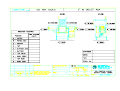
LOMA AXIS
RADIATION SURVEY REPORT
X-RAY FOOD INSPECTION UNITS
1. Unit Details:
Model/Type:__________________________ Customer: ____________________________
Serial No:____________________________ Address: _____________________________
Year of manufacture:___________________
______________________________
Location of unit:_______________________
______________________________
Reason for survey:
Installation
Post-maintenance
Relocation
Other (specify)_____________________________________________
2. X-Ray Tube Settings:
_________ kV
__________mA
3. General Checks:
Adequate guarding fitted ……………..
Customer information provided …………
‘Power On’ warning lights labelled, visible from both sides and operate correctly………….
‘X-ray On’ warning lights labelled, visible from both sides and operate correctly……………
‘Fault’ warning lights labelled, visible from both sides and operate correctly………………..
Emergency stops fitted, labelled and operate correctly ………………………………………..
Conveyor interlocks fitted and operate correctly ……………………………………………….
X-ray warning labels fitted to infeed and outfeed ..…………………………………………….
4. Dose Rate Results: (Refer to relevant unit drawing)
For measurement point dose rates see attached Drawing No:_________________________
External dose rate less than 1µSv/h .…………………………………………………………...
5. Radiation Monitor used:
Model/Type:
Serial No:
Calibration Date: _______ ___
Comments:
Test conducted by approved Engineer
Name:___________________ Signature:_______________________ Date:_____________
Principles of Inspections
PRINCIPLES OF INSPECTION
CONTENTS
X-Ray Generation
Detection of X-Rays
Product Absorption
Imaging Software
Contaminant Detection
Module 4000
Principles of Inspections
X-Ray Generation
X-rays are one of many types of electromagnetic radiation that are produced for a particular
use. At some time or other most people will have received medical treatment or diagnosis,
which will have involved the use of x-rays. Indeed used in the correct manner x-rays can be
safely produced and have a number of uses, one of which is for the inspection of food
products.
Note: X-rays cannot make food products radioactive, as soon as the power source ceases xray generation stops and no residual radiation is present.
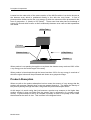
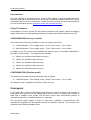
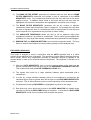
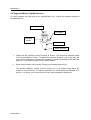
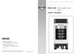
The principle of x-ray generation is one that is simple to understand and is shown in the
diagram below. An evacuated glass tube is used to house a cathode (-ve terminal) and an
anode (+ve terminal) which is itself then housed inside a led lined oil filled tank which
electrically insulates the tube from the case. In addition the oil is circulated and cooled to
dissipate the unwanted heat that is generated when x-rays are produced.
A filament emits electrons inside the tube and a high voltage is then applied which
accelerates the electrons towards the target on the anode. When the electrons hit the target
x-rays are given off in the form of a conical shaped beam. In effect the voltage controls the
brightness and the current the contrast.
X-RAY TUBE
Current (mA)
ELECTRON
.
.…
……
……..…
…………...
X-RAY BEAM
>>>>>
High Voltage
(kV)
Ground
Potential
Detection of X-Rays
Once x-ray generation has taken place and we have the aforementioned conical shaped
beam, the next step in the process used on the AXIS machine is to include a device which
will receive the x-ray energy and process its signal values.
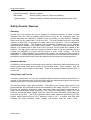
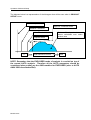
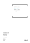
To do this we first position an assembly directly under the x-ray tank known as the collimator.
The collimator in effect allows only the small centre section of the x-ray beam to be emitted
approximately one millimeter in thickness. This section of the beam can be considered to be
fan shaped and positioned at ninety degrees to the product flow direction as shown in the
diagram below
Module 4000
Principles of Inspections
Located on the under side of the centre section of the AXIS machine is a device known as
the detector array which is positioned directly in line with the x-ray beam. A line of
photosensitive diodes receive the x-ray energy of which the values are then processed in the
form of grayscales - 0 (black) to 255 (white) . These scan lines take place at hundreds of
scans per second which means a direct relationship between scan rate and belt speed/flow
rate exists.
X-Ray Tank
Collimator
Detector Array
X-Ray Beam
Product
When product is not passing through the x-ray beam the detector array receives 100% of the
x-ray energy over the entire length of the array.
When product is introduced through the beam less than 100% of x-ray energy is received of
which the signal values will be processed and shown as a grayscale image.
Product Absorption
When we refer to the product absorption level we mean the amount of x-ray energy that the
product will consume (absorb) when x-rays are passed through it. The higher the density of
the product passing through the beam, the greater the product absorption factor.
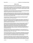
At this stage it is worth noting that just because a product may measure to be higher than
another product it does not follow that the greater size is necessarily of a greater overall
density. A good example of this is to compare a quantity of water to a quantity of ice cream
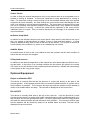
that measures the same in size. This is shown in the diagram below.
Module 4000
Principles of Inspections
100mm of
Ice Cream
100mm of
Water
The density (absorption factor) of the water is approximately
two times greater than the density of the ice cream. This is
mainly due to the fact that ice cream consists of a greater
amount of air compared to water.
It can therefore be seen that the 100mm of water will absorb a much higher level of x-ray
energy than an equivalent quantity of ice cream. In turn the detector array mentioned earlier
would receive a lower quantity of x-ray energy through the water compared to the ice cream.
The consequence of this is one that generates a lighter grayscale image on the screen in the
case of the ice cream.
Further to our examination into product absorption it is important to remember that not all
products will have an even absorption factor across its entire area. The ‘water’ ‘ice cream’
example shows the density differences assuming both products are homogeneous.
In the case of a particulate product it must be understood that density values will vary across
the entire area of the product. Therefore it follows that the level of x-rays reaching the array
(detector) will also vary. This will result in an image being shown on the screen of varying
grayscale levels. An example is shown below of the effect a particulate product will have in
terms of absorption factor.
A
B
A = 2 x Absorption
B = 5 x Absorption
C = 3 x Absorption
Module 4000
C
C
Principles of Inspections
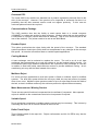
When we talk about the absorption factor it is useful to know that the density value is
dependant on the specific gravity of the product and that by multiplying the specific gravity
value of the product by the height, we can calculate the absorption factor.
Equating Absorption
H20
75mm
Water has an SG (specific gravity) of 1.
multiplying the product height by the SG.
75mm
The relative absorption can be derived from
In the example above the absorption factor is 75 x 1 = 75
By introducing a 1mm steel contaminate of SG = 8, the absorption of the water has been
reduced to 74 x 1 (1mm displacement) but the overall absorption factor has increased.
(74 x 1) + (1 x 8) = 82, a 9% increase
The system detects the density change. If the above example is changed to 5mm high an
even larger increase is observed.
5 x 1 = 5 now becomes (4 x 1) + (1 x 8) = 12, a 140% increase
From the following diagram it can be seen that contaminate A is more easy to detect than B.
With B the x-ray beam passes through more of the product and therefore has a higher
absorbency factor.
Module 4000
Principles of Inspections
A
B
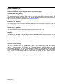
Imaging Software
On the PC mounted in each x-ray machine is loaded software dedicated to the image
acquisition, analysis and viewing on the monitor. The version being run on a particular
machine is shown in the blue start screen.
Parameter values are then setup to optimize the system performance and requirements
suitable for each application.
Contaminate Detection
The analysis is carried out by comparing each image pixel to a threshold value and rejecting
anything below this value i.e. it is denser and hence darker than the product itself. This
relationship to density means that if a contaminate is close to water (it floats) then it cannot
be detected e.g. insects, wood, hair or paper.
Module 4000
Installation
INSTALLATION
CONTENTS
Installation - Mechanical
Installation - Electrical
Installation - Pneumatics
Checking and Powering Up
Module 5000
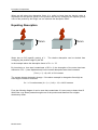
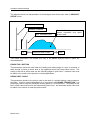
When moving the AXIS
conveyor machine place
the forks in the indicated
position. Care must be
exercised when lifting and
moving the AXIS making
sure that the control unit is
not too close to the fork lift
face. In addition care must
be taken to make sure that
the AXIS cannot slip when
the forklift is in motion.
LIFTING AND MOVING AN
AXIS MACHINE
AXIS CONVEYOR
INCLUDING RAPID
PLACE FORKS HERE
AXIS PIPELINE
PLACE FORKS HERE
When moving the AXIS
pipeline machine place the
forks in the indicated
position. Care must be
exercised when lifting and
moving the AXIS making
sure that the control unit is
not too close to the fork lift
face. Be aware that the
centre section must be
locked in place before
attempting to move the
machine. In addition care
must be taken to make
sure that the AXIS pipeline
machine cannot slip when
the forklift is in motion.
Installation
Installation - Mechanical
Pre-Installation Note For Pipeline Machines
Please note that the infeed and outfeed product pipes need to be fixed to ensure they
remain stationary when machine is normalised. These fixings are the responsibility of
the user unless supplied with the machine under the agreed machine specification.
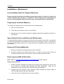
Preparing to Install the Machine
The system is dispatched from Loma Systems in the following state:
1)
Feet are screwed fully in.
2)
The X-Ray tank breather screw is in and locked.
3)
Delicate items are covered in protective wrapping material and attached or boxed (i.e.
lamp stack)
Space Required for Installation and Maintenance
It is important that sufficient free space is left at the front and back of an AXIS x-ray machine
to enable commissioning and maintenance personnel to easily gain access to components.
It is recommended that a minimum of 1 metre free space is available at the front and rear of
the machine.
Removal of Packing Materials
1.
Remove and discard all packing and protective materials.
2.
All AXIS machines are delivered secured to a pallet by 12mm bolts, which are
screwed through the feet of the machine. Remove these bolts where fitted.
Removing the AXIS off the Pallet
Note: Refer to LIFTING AND MOVING AN AXIS MACHINE in this section.
Using a Fork Lift Truck
1.
Position the forks beneath the machine at the lifting points indicated so that it does
not tilt (Refer to LIFTING AND MOVING AN AXIS MACHINE). Raise the lift
sufficiently to lift the machine clear of the pallet and any obstacles.
2.
Carefully move the machine to the required location following the advice stated in
LIFTING AND MOVING AN AXIS MACHINE.
3.
Lower the forks and withdraw them from the machine.
Module 5000
Installation
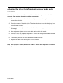
Adjusting/Levelling the Machine
1.
Level the machine by adjusting the foot studs. The stud flats are 17mm A/F. Make
sure that all feet are firmly on the ground, and are evenly supporting the machine so
that it does not rock. If necessary, anchor the machine to the ground using bolts
screwed through the feet.
2.
Due to the fact that each AXIS machine has an oil filled tank (which the x-ray tube is
immersed in) it is necessary to level the machine to ensure that 100% of the x-ray
tube is immersed. To this end use a spirit level across the top of the cabinet, in the
direction of flow, adjusting the feet until a level condition is achieved.
3.
When the height and level is correct, lock the foot stud half-nuts. The lock nut
hexagon is 30mm A/F. Failure to do so can have an adverse effect on the
components of the AXIS x-ray system.
4.
You are recommended to apply silicone sealant around the feet and floor.
Unlocking the X-Ray Tank Breather
Each AXIS machine is delivered with the x-ray tank breather screw locked. Therefore it
follows that this screw needs to be unlocked before powering up the machine.
To do this open the rear access door at the back of the upper rear cabinet. The breather
screw is easily located on the top of the x-ray tank filler plug. Loosen the screw by two or
three turns anti-clockwise and close access doors.
It should be noted that conveyors fitted with other forms of cooling other than a vortex may
require the complete top lid to be removed to gain access.
Installation - Electrical
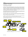
Connecting Electrical Supplies
The supply voltage for the system is indicated on the identification/rating plate that is
mounted on the frame. The maximum line current is also shown
1.
Open the door on the front of the centre section cabinet to access the electrical
services area.
2.
The isolator switch is located at the bottom left hand side of the cabinet. Beneath it
on the bottom of the cabinet is the cable gland access for the power cable.
Module 5000
Installation
3.
The system-input power will depend on the country and system type that has been
delivered. For details refer to the rating plate mounted on the frame of the AXIS
machine in conjunction with the wiring diagrams delivered with the user manual.
4.
Split the cable inside the box and cut the wires to suitable lengths. An
armoured/braided cable is recommended when cable conduit is not used. A suitable
earth conductor is also to be fitted.
5.
Refer to Figure below for isolator switch wiring details. Make the connections to the
isolator switch as specified in Table 1.
Live Terminal
Neutral
Earth or
PE
Terminal
Live Terminal
Live Terminal
Isolator Switch Terminals
European
Colour
North America
Colour
Terminal
LIVE
Brown or black
HOT
Black
1/3/5
NEUTRAL
Blue
NEUTRAL
White
N
EARTH
Green/Yellow
GROUND
Green
E
SCREEN
-
SCREEN
Table 1 Electrical Supply Connections
6.
Check that all connections are secure then close and lock the door.
Module 5000
-
E
Installation
Installation - Pneumatics
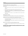
Connecting the Air Supply
All AXIS x-ray systems require a compressed air supply, primarily to operate the automatic
reject system. In addition the standard AXIS conveyor model requires a further air supply to
feed the vortex cabinet cooler situated on the top of the central cabinet. In this situation when
a reject occurs operation of the vortex is inhibited to allow maximum air to the reject
mechanism. It is therefore essential that the air supply is robust enough for correct operation
of the Axis machine when either the reject or vortex operate.
The AXIS pipeline machine also requires an additional air supply for the operation of the
shutter piston located by the side of the collimator. The minimum air pressure must not fall
below 65psi (4.5 bar) when the reject operates on all models.
In the case of a pusher reject, a dump valve is also fitted in order to protect an operator in
case of an emergency. As soon as an emergency stop is activated the mains air supply is
shut off and all air is exhausted from the system.
In addition for failsafe reasons an air pressure switch is fitted in order to alert the operator
that the air supply is low and shut down the system generating a fault condition.
The mains air supply is to be connected as shown below to the input side of the air regulator
and should be set to 5.5 bar (80 psi).
Isolator
Switch
Air
Regulator
Dump Valve
Soft Start
Reject Valve
Air
Supply In
Water Drain
Air Pressure
Valve
)
Vortex Valve
Pneumatic assembly (pipeline shutter valve not shown)
Module 5000
Installation
Checking Guards
1.
Check that all guards and interlocks are securely fastened in place.
2.
Check that the infeed and outfeed of the system are clear of obstructions.
Powering Up the System
WARNINGS
1.
LETHAL HAZARD – ELECTRICAL AND COMPRESSED AIR SUPPLIES. This
equipment uses electrical and compressed air supplies that can be lethal. Unless
absolutely necessary, work must not be carried out without first isolating the
equipment from all electrical and compressed air supplies.
2.
LETHAL HAZARD – RADIATION. Whilst every precaution has been taken to make
sure that all the necessary guards and safety devices have been fitted to the Loma xray unit, it is recommended that all operatives are trained in the use of x-ray food
inspection machines. In addition users must adhere to the necessary requirements
required by their country, state or province. Furthermore it is the responsibility of the
employer to create a set of local rules (see example in Cautionary Advice) regarding
the safe use of x-ray food inspection systems. In the U.K. this is in compliance with
the Ionising Radiation’s Regulations 1999, users outside of the U.K. should consult
the relevant health and safety executive (see also Radiation Surveys).
3.
WORKING ON EQUIPMENT. If it is essential to work on the equipment with
electrical and/or compressed air power connected, the work must be undertaken only
by qualified and authorised personnel who are fully aware of the danger involved and
who have taken adequate safety precautions to avoid contact with dangerous
voltages, compressed air supplies or radiation.
4.
Each x-ray system manufactured by Loma Systems is fitted with emergency ‘Stop’
buttons. These are mounted on the front and sides of the control panel and at the
rear of the machine. In the case of a pipeline machine, due to the size and no
conveyor present only one emergency stop is required and this is situated on the front
control panel. The buttons are red in colour with a yellow background. In the event of
an emergency, which requires the machine to be immediately stopped, press the stop
button and both x-rays and the conveyor will be stopped. In addition an alarm will
sound and an amber lamp will be illuminated.
Module 5000
Installation
5.
Before powering up any AXIS machine for the first time, a suitably qualified person
should be present to carry out a critical examination (see Radiation Surveys). For
advice please contact your local Loma Service office.
6.
Switch on the compressed air supply to the system and open air isolator switch.
7.
At the bottom left hand side of the central electrical services cabinet switch on the
mains isolator. The system automatically boots up in a failsafe fault condition with the
alarm sounding and the amber fault lamp on.
8.
Press the amber fault reset button, the alarm should stop and then again to clear the
amber fault lamp.
9.
On fixed speed conveyor models only operate the green ‘Start’ switch located on the
system control panel. Check that the Conveyor belt runs in the correct direction. If
incorrect swap two of the phase cables over in the incoming supply. Variable speed
conveyors will be correct and not need adjustment.
10. At this stage contact an authorised key holder to insert the key into the x-ray key
switch and switch to the on position. Refer to operators guide and setup section for
further details.
Checking Belt Tracking
The belt must be checked for correct tracking before running the conveyors for any length of
time. The tracking adjusters are found adjacent to the end rollers of the AXIS conveyor
machine.
If belt tracking needs to be reset, carry out the belt tracking procedure described in the
section titled Routine Maintenance (Weekly/Monthly) in the Maintenance section of this
manual.
Setting Up Reject
WARNING
REJECT DEVICES. At no time, with air and/or electrical power applied to an automatic
reject device, should any part of the body be placed within the operating area of the
reject device.
General
The system is normally supplied with the reject mechanism correctly set up for at least one
product. If the Reject Delay and Dwell times need to be adjusted for further products, these
are set up via the user interface. Refer to the sections titled Reject Setup in the operators
guide.
Module 5000
Installation
Pusher and Plough Rejects
The system is supplied with the reject cylinders already set, and normally no further
adjustment should be necessary.
In certain instances Loma may supply a Reject Device only, and the end user supplies the
Reject Catchment Device, Bin / Table, etc. The safety of the Reject Device is therefore a
function of the design of the User’s Reject Catchment Device. It becomes the User’s
responsibility to ensure the safety of the complete Reject System.
In most instances the product is delivered onto the system by conveyors. The System has to
have entry and exit points. There is a possible hazardous area at the transfer between the
conveyors. Loma rely on the total line being made safe by the End User.
WARNING
The internal cabinet areas of the machine contain electrical devices which are at 240V,
220V or 110V potential depending on the supply voltage. These voltages may cause
injury or death on contact. Work in this area should only be carried out by a qualified
Technician with the Isolator switched off. (The Isolator is located at the bottom lefthand side of the Electrical Services Box).
Diagnostic work should not be undertaken unless the Technician has been Loma trained.
WARNING
For fixed speed conveyors and pipelines located in a wet environment a Ground Fault
Interrupter or RCCB must be used. This is not recommended for variable speed
conveyors as the inverter may cause the device to trip.
Module 5000
ATTENTION
IT IS IMPERATIVE THAT THIS MACHINE IS
CORRECTLY EARTHED.
PLEASE CHECK SUPPLY VOLTAGE BEFORE
SWITCHING ON.
Errors will affect Loma warranty
For Axis fixed speed conveyor machine
Module 5000
ATTENTION
IT IS IMPERATIVE THAT THIS MACHINE IS
CORRECTLY EARTHED.
THIS MACHINE SHOULD NOT BE SUPPLIED VIA AN
EARTH LEAKAGE CIRCUIT BREAKER (RCD)
PLEASE CHECK SUPPLY VOLTAGE BEFORE
SWITCHING ON.
Errors will affect Loma warranty
For Axis variable speed conveyor machine
Module 5000
ATTENTION
IT IS IMPERATIVE THAT THIS MACHINE IS
CORRECTLY EARTHED.
PLEASE CHECK SUPPLY VOLTAGE BEFORE
SWITCHING ON.
Errors will affect Loma warranty
THIS MACHINE WILL EMIT X-RAYS IF NOT
CONNECTED USING OFFSET FEED PIPES OR IN
A PIPELINE & SHOULD NOT BE
ENERGISED UNTIL CORRECTLY INSTALLED.
For Axis pipeline machine
Module 5000
Product Descriptions
PRODUCT DESCRIPTIONS
CONTENTS
Technical Specification
X-Ray Subsystem
Conveyors
Safety Guards/Devices
Reject types
Electrical services
Other standard equipment
Optional equipment
Module 6000
Product Descriptions
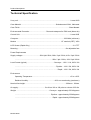
Technical Specification
X-ray unit…………....................................................................................................Loma AXIS
Case Material ........................................................................... Stainless steel 304L, fabricated
Case Finish ........................................................................................................... Bead blasted
Environmental Protection .................................... Dust and waterproof to IP66 level (Nema 4x)
Control Unit ..............................................................................................................Loma AXIS
Computer....................................................................................................933 MHz (minimum)
Monitor .............................................................................................. 15” nominal (CRT), VGA
LCD Screen (Rapid Only) ........................................................................................... 12.1 TFT
Mounting........................................................................................................On adjustable feet
Power Requirements
Supply voltages .................................... 220v/1ph/ 50Hz, 380v / 3ph / 50Hz, 415v / 3ph / 50Hz
................................................................................ 220v / 3ph / 60Hz, 110V /1ph / 60Hz
Load Current (typical) ..........................................................Conveyor - 110V / 11A, 230V / 6A
......................... ……………………………………………. Pipeline - 110V / 5A, 230V / 2A
............................……………………………………………. Rapid - 110V / 5A, 230V / 2A
Environment
Operating Temperature................................................................................ +2º to +40ºC
Relative Humidity ......................................................... 90% non-condensing (maximum)
Nominal line height......................................................................................... 900mm ± 100mm
Air supply..........................................................5 to 8 bar / 80 to 100 psi at a volume of 25 cfm
Weight .................................................................. … Conveyor - approximately 550 kilograms
.................................................................... ……. Pipeline - approximately 350kilograms
....................................................................... ……. Rapid - approximately 250kilograms
Module 6000
Product Descriptions
X-Ray Subsystem
The x-ray components and control system are contained inside the central stainless steel
cabinet.
X-Ray Tank
The x-ray tube is mounted inside an oil-cooled tank connected to a mains driven pump and a
fan cooled radiator. In order to stop the x-ray tube from overheating the oil passing through
the radiator is cooled and re-circulated through the x-ray tank. The oil used is a mineral
based transformer oil and should be treated as a such when considering handling and
disposal requirements.
High voltage PSU
The x-ray power is supplied by a high voltage power supply, which controls the power level
(kV) ranging from 20 to 75 kV depending on the model (low or high power).
Filament PCB
The current (mA) supplied to the filament in the tube is regulated via a separate PCB known
as the filament board.
Detector Array
The detector array comprises of a line of photosensitive diodes (the number varies
depending on width of conveyor - 256 diodes for 200mm wide, 384 diodes for 300mm wide,
640 diodes for 500mm wide and 768 diodes for 600mm wide - which receive the x-ray energy
emitted from the x-ray tube. The detector scans at a rate of hundreds per second (typically
620) depending on the belt/product speed. Both serial and parallel connections go directly to
the PC, the parallel connections providing the image data and the serial connection allowing
full control of the sensor by the PC. The PLC provides timing signals in the form of the 'scan'
and 'acquire' signals.
PLC
The PLC has a number of functions. Two of which controls and monitors both the power
level and the current supply to the x-ray tube. In addition monitoring and control functions of
the various systems is also undertaken. This includes the reject signal and serial
communication to the PC.
PC (Computer)
The PC is also located in the centre section of the AXIS machine and is where the control
software, image processing software and hardware are located. Data is received from the
detector, analysed and then displayed on the monitor. The PC also communicates with the
PLC. When power is removed from the system e.g. due to a power failure the PC operating
system will still shut down in an orderly manner due to a small internal UPS which maintains
power for at least the duration of this process.
Module 6000
Product Descriptions
User Interface
The user interface is a display monitor, which is fitted behind a clear polycarbonate panel.
Down the right hand side and below are a number of membrane switches which are used in
conjunction with the screen information. Down the left hand side are the control switches.
For more information see the Operators Guide User Interface Section.
X-Ray PC Software
This software is used to provide for the operator interface to the system, gather and display
image information of product passing through the machine and communicate with the PLC.
CONFIGURATION (Conveyor model)
One of two power levels are provided on each unit and are as follows:
a)
100 Watt System, Tube voltage (max) = 50 kV Tube current = 1.0 to 2.0mA
b)
400 Watt System, Tube voltage (max) = 75 kV Tube current = 1.0 to 5.0mA
In addition to the two power levels available the detector array is selectable dependant on
the width of the conveyor. Two variations are available.
a)
205mm (for a 200mm wide Rapid conveyor)
b)
307mm (for a 300mm wide conveyor)
c)
512mm (for a 500mm wide conveyor)
d)
614mm (for a 600mm wide conveyor)
e)
666mm (for a 650mm wide conveyor)
CONFIGURATION (Pipeline model)
The pipeline is provided with only one power level as follows:
a)
100 Watt System, Tube voltage (max) = 50 kV Tube current = 1.0 to 2.0mA
The detector array is supplied in the 307mm wide unit only.
Conveyors
A 370 watt 0.5hp (187W for the Rapid) motor drives the conveyor which is as standard is
fixed speed but if specified can be variable speed via an inverter. In addition the conveyor is
fitted with a suitable reject system that will best ensure that contaminated product is
successfully placed in a suitable container e.g. reject bin.
The non-crack surface makes it easier to clean and in addition is non-absorbent. The
standard belt supplied is PU but Intralox belt may be supplied if required. The conveyors are
supplied in the following standard sizes:
Module 6000
Product Descriptions
Nominal line height: 900mm ± 100mm
Belt widths:
200mm (Rapid), 300mm, 500mm and 600mm
Typical Lengths:
1900mm (Rapid), 2100mm (Standard) and 2800mm (Bulk Flow)
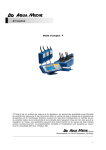
Safety Guards / Devices
Guarding
As with any x-ray machine the use of guarding is extremely important in order to shield
operators from the ionising radiation present when x-rays are on. Legislation sets very
specific demands with regards to radiation limits surrounding a x-ray machine. Radiation
levels must not be greater than 1.0µSv per hour. The level emitted from the Loma AXIS
machine is much less, on average not greater than 0.1µSv per hour. This is achieved by
engineering and design. The stainless steel construction creates most of the shielding
required with the addition of four lead loaded curtains. These are fitted at each side of the
internal x-ray cabinet and at both ends of the conveyor for the infeed and outfeed of the
machine. For high power units two curtains are fitted at each of the four locations; the two
curtains are staggered to ensure that the fingers of each curtain overlap. For these
applications it is important that if for any reason the curtains are removed that this overlap is
maintained. In certain bulkflow applications the curtains may not be fitted and protection is
provided by the fact that access cannot be obtained via the infeed and outfeed apertures.
Interlock switches
In addition to the shielding of the guards, each machine is fitted with interlock switches on all
access panels that would allow access to the radiation areas. When opened x-rays will
switch off and a fault condition is generated. There is no residual radiation present when xrays are off.
Safety Relay and Circuits
As safety is paramount, two (one on a pipeline) failsafe relays are fitted to ensure that if a
contact of the interlocks were to fail the safety relay will automatically detect the fault and
therefore shut down x-rays and activate a fault condition.
The conveyor safety relays work as follows. The infeed cover, outfeed cover and the rear
panel interlocks are connected in series and monitored by the safety relay ES1. A contact of
ES1 and the remaining emergency stops, back door, lower panel and lid interlocks are in
series and monitored by safety relay ES2. The 'Tank Over temperature' switch, ES1 and
ES2 then control the 'Mains Voltage' relay RL1. Both this circuit and safety relays status are
monitored by the PLC. The PLC programme utilizes these signals to generate the 'X-Ray
Enable' output which tells the PC to generate x-rays or not. A contact from ES2 also
switches the main contactor which controls the inverter and the motor circuit.
Module 6000
Product Descriptions
Reject Types
Loma x-ray machines are supplied with the following reject types:
•
Air Blast reject;
•
Pusher reject;
•
Ball valve (pipeline only)
Alternatively, a conveyor or pipeline can be supplied without a reject device with a ‘Signal
Only’ output. On detection of a contaminant in the product, the control unit provides an
output signal only. This can be used for wiring into other equipment such as a PLC.
Air Blast Reject
An air blast reject is pneumatically operated. On detection of a contaminant a high-pressure
blast of compressed air is directed from the air blast reject device to the product, causing the
contaminated product to be blown off the belt into the reject bin.
Pusher Reject
A pusher reject is pneumatically operated. On detection of a contaminant the compressed
air supply activates the pusher, causing it to push the contaminated product off the belt into
the reject bin.
Pneumatic Specification for reject type
Pusher
Optimum supply pressure………………………………….5.5 Bar (80 psi)
Minimum supply pressure…………………………………..4.5 Bar (65 psi)
Maximum supply pressure………………………………… 6.0 Bar (90 psi)
Capacity (Litres/second at 100 psi)……………………….………………10
Air Blast
Optimum supply pressure…………………………………6.8 Bar (100 psi)
Minimum supply pressure…………………………………5.5 Bar (80 psi)
Maximum supply pressure………………………………..8.0 Bar (120 psi)
Capacity (Litres/second at 100 psi)………………………………………20
Module 6000
Product Descriptions
Electrical Services
Electrical services to the x-ray machine are inside the main x-ray cabinet with mains cable
entry points in the bottom. The conveyor contactor and overload are also located inside the
main x-ray cabinet. For conveyor motors controlled by an inverter no overload is fitted.
The isolator is used for isolating the electrical power to the machine and is located at the
lower left-hand side of the x-ray cabinet.
Safety Devices
Each x-ray machine is fitted with emergency ‘Stop’ buttons and cover/panel interlocks.
These when operated, switch x-rays off and exhausts air out of the reject device (where
applicable).
Other Standard Equipment
Air Pressure Switch
An air pressure failure switch is fitted to both the conveyor (excluding the Rapid) and pipeline
models. The switch is set by Loma to operate if the pressure of the compressed air supply to
the machine falls below approximately 3 bar (42 psi). The conveyor then stops x-rays switch
off and the fault alarm and lamp are activated. In the case of the pipe line all above will take
place and the reject will stay open for failsafe operation.
Product Registration Photo-Electric Cell
The Loma AXIS conveyor model is supplied fitted with a photoelectric Cell (PEC) as
standard. The PEC is mounted on the side of the conveyor just prior to the x-ray beam. It is
used to register the position of the products on the conveyor. As an option, the PEC may be
mounted directly above the belt. This is particularly suitable for the registration of products
that have very little depth (flat).
Bulkflow machines are not fitted with a PEC.
Internal cabinet thermostat / cooler
A thermostat is normally fitted to guard against system overheat. Pipelines and some low
power conveyors may not require cooling. If the internal temperature of the cabinet should
reach the set limit the thermostat will switch on a solenoid valve which in turn activates the
cooler (type will vary depending on application) to cool the internal temperature. This is set
at manufacture and should not be changed.
Module 6000
Product Descriptions
Vortex Cooler
In order to keep the internal temperature of the x-ray cabinet down to an acceptable level, a
method of cooling is installed. It should be noted that in some applications no cooling is
fitted. For those with cooling a vortex cooling unit is the standard method used (see optional
equipment for other methods). Air flows through the vortex cooler and is discharged into the
main x-ray cabinet at a much-reduced temperature. The vortex does not operate all the time
but only if necessary and operators should be made aware that it may operate at anytime
when the machine is running. It should be noted that the operation of the vortex will be
inhibited if there is a reject. This is to ensure that there is a full supply of air available to the
reject mechanism.
Indicator lamp Stack
In addition to the indicator lamps on the control panel a lamp stack is also fitted on the top of
the x-ray cabinet to indicate power on (white), x-rays on (red) and fault (amber). In some
cases an additional lamp stack is fitted at the front of the cabinet. This is done to ensure all
round visibility of the indictors e.g. when an air conditioning unit is fitted.
Audible Alarm
An audible alarm is fitted to the x-ray cabinet to alert the operator that the fault condition is
active and the conveyor has stopped.
X-Ray tank sensors
In addition to the internal temperature of the cabinet two extra thermostats are fitted to the xray tank itself. In the event of an overheat condition the first sensor will signal to the control
unit, which in turn will activate a fault condition and the second as a failsafe will automatically
cut the power to the x-ray power supply.
Optional Equipment
Reject confirmation PEC
This device is normally fitted across the aperture of a reject bin directly in the path of the
rejected product. If the rejected product does not break the photocell beam in a given time a
fault condition is activated. The conveyor will then stop and the operator will be alerted by
means of an audible alarm and lamp. The fault will be displayed on the front screen.
Bin full PEC
This device is normally fitted near to the top of the reject bin. If the bin should fill up with
rejected product there is a danger that further rejected product could be deflected back on to
the conveyor and into the good product path. If a bin full photocell is fitted, the rising product
will break the photocell beam and will activate a fault condition. The conveyor will then stop
and the operator will be alerted by means of an audible alarm and lamp. The fault will be
displayed on the front screen.
Module 6000
Product Descriptions
Overhead PEC
The Loma AXIS x-ray machine as standard has a product registration photocell fitted to the
side of the conveyor. However if the product to be inspected is extremely flat there is a
possibility that the side mounted version could not register positively. In this case an
overhead photocell would be required.
Communications Package
The AXIS machine also has the facility to send reports back to a central computer
(LOMANET) to collate and archive for later reference. Another option that can be supplied is
a connection to a printer (remote hand held or desktop). This is via a serial link port at the
rear of the machine. The printer needs to be set at rate 9600 Baud.
Encoder Reject
This option synchronises the reject timing with the speed of the conveyor. The standard
system operates a timed reject, which does not compensate for any changes in the conveyor
belt speed. An encoder is therefore fitted on variable speed applications.
Cooling Methods
A heat exchanger can be selected to replace the vortex. The unit is an air to air heat
exchanger that uses ambient air to cool the cabinet air via two isolated cooling circuits. For
environments where high ambient temperatures are expected a heat exchanger is used but
in addition is fitted with peltier semiconductor coolers to provide additional cooling. An air
conditioning unit may also be fitted instead of the vortex.
Multilane Reject
For some conveyor applications a dual lane system is fitted or multilane reject for bulkflow
systems. The dual lane system divides the conveyor width into two and product is passed
down in two rows. Multilane reject systems consist of up to 8 reject flaps across the width of
the belt; so that in bulkflow mode only the minimum product is rejected when necessary.
Mass Measurement / Missing Product
These are two special functions incorporated into the software if requested. Also separate
rejects in addition to the contaminate can also be incorporated if required.
Variable Speed
Due to production constraints a variable speed conveyor may be necessary. This is done by
controlling the motor via an inverter instead of direct on line.
Roller Track Reject
This is fitted instead of the reject bin. Reject conformation and bin full PECs may also be
fitted if required.
Module 6000
Operators Guide and Setup
OPERATORS GUIDE AND SETUP
CONTENTS
Conveyor Layout Drawing
Pipeline Layout Drawing
Description of Analysis Modes and Parameters
User Interface (Conveyor & Pipeline)
Start Up Procedure
Normalisation
Menu Map (Conveyor)
Password Protection
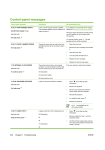
Fault and Error messages
Reports
System Display Screens
Supplements
Module 7000
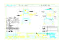
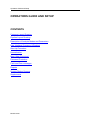
AXIS CONVEYOR LAYOUT DRAWING
LAMPSTACK
VORTEX COOLER
RED XRAY ON
EMERGENCY
STOPS
TOP PANEL ACCESS
TO XRAY TANK AND
PUMP
REAR PANEL
ACCESS TO XRAY
TANK AND PUMP
AMBER FAULT
WHITE POWER
OPERATORS
CONTROL
PANEL
GUARDS
INTERLOCKS
FRONT PANEL
(ELECTRICAL SERVICES)
REJECT BIN
CURTAINS
PNEUMATICS
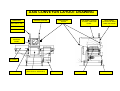
AXIS RAPID LAYOUT DRAWING
LAMPSTACK
RED XRAY ON
EMERGENCY
STOPS
AMBER FAULT
TOP PANEL ACCESS
TO XRAY AND
ELECTRICAL
SYSTEMS
REAR PANEL
ACCESS TO XRAY
AND ELECTRICAL
SYSTEMS
WHITE POWER
OPERATORS
CONTROL
PANEL
CURTAINS
PNEUMATICS
GUARDS
REJECT BIN
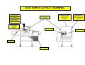
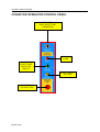
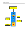
AXIS PIPELINE LAYOUT DRAWING
LAMPSTACK
RED XRAY ON
REJECT VALVE (LEE
BALL) AS STANDARD
OPTION
OUTFEED
SAFETY
INTERLOCK
REAR PANEL
ACCESS TO XRAY
TANK AND PUMP
TOP PANEL ACCESS
TO XRAY TANK AND
PUMP
AMBER FAULT
WHITE POWER
SAFETY INTERLOCKS
(CENTRE PIPE ACCESS)
OPERATORS
CONTROL PANEL
DIRECTION OF
TRAVEL FOR
CENTRE PIPE
ACCESS
INFEED SAFETY
INTERLOCK
VENTING DUCTS
FRONT PANEL
(ELECTRICAL SERVICES)
RELEASE CATCH AND PULL
CENTRE SECTION
FORWARD TO NORMALISE
RELEASE KNOBS
TO ACCESS
PRODUCT PIPE
CENTRE SECTION
PNEUMATICS
ASSEMBLY PLATE
LOCATION DEPENDANT
ON M/C HANDING
Operators Guide and Setup
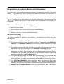
Description of Analysis Modes and Parameters
The Loma AXIS range of machines has been designed to incorporate a number of inspection
modes. This enables the user to optimise the system and choose the best mode of
operation that suites the product and line conditions.
The following pages will describe the different analysis modes and parameters, which will aid
the user in setting up the AXIS machine for optimum performance. The user should also
refer to the relevant menu map for their machine and descriptions in the Glossary of
Parameters.
The Analysis Modes are in the following order:
1)
Auto (Conveyor model)
2)
Auto with Bone Filter (Pipeline and conveyor bulkflow models)
3)
Explorer (Conveyor, Pipeline and bulkflow models)
AUTO (Conveyor Model)
This mode of analysis is standard on all machines. The inspection is carried out in the
following way:
1)
Inspection is started when the PEC is triggered by the product.
2)
The system captures an image the length of which is determined by the PRODUCT
LENGTH. The PRODUCT LENGTH must be correctly entered otherwise not all the
product will be analysed.
3)
The system examines the image and looks for the product by locating the first row of
data that is darker than the set figure in the PRODUCT LOCATOR entry box.
4)
The whole of the greyscale area is then examined so as to calculate its greyscale
distribution and texture level whereupon an Auto threshold (reject point) will be set.
In addition to the calculated Auto threshold we can manually increase or decrease
sensitivity by adjusting the AUTO SENSITIVITY.
5)
The system will then check the contam size count whereby if it is higher than the
manually set CONTAM SIZE and lower than the AUTO THRESHOLD value a reject
will be registered. In addition the contaminant will be highlighted in red on the image.
6)
The CONTAM THRESHOLD allows the user to set an absolute reject point
regardless to whether it is product or contaminant. This is useful to guard against the
possibility of a very large lower density contaminant being factored into the histogram.
7)
Window Top and Window Bottom is set to limit the inspection width. This may be
set to exclude fixed objects (such as product guides) from the analysis area.
Module 7001
Operators Guide and Setup
The diagram below is a representation of the histogram that will be seen when in PRODUCT
SETUP screen.
Number of pixels
Absolute Threshold
Auto Threshold Level
0
GREYSCALE LEVEL
Product Density levels and
texture calculated over entire
product area
255
Two further parameters are located and used in the AUTO analysis mode of which are
described below:
ERODE TOP / BOTTOM
This parameter should be used when the leading and trailing edge of a box or container is
thick enough to cause a dense area to be registered which may cause false rejects. The
setting of this will in effect mask out the offending edges in pixel count. However care must
be taken not to mask out the product in certain applications.
ERODE LEFT / RIGHT
This parameter (similar to the last) is used in the case of a product having a dense edge on
the sides. It can be used independently or in conjunction with ERODE TOP/BOTTOM. It is
particularly used to stop the possibility of false rejects in a round product. The setting of this
will in effect reduce the area to be inspected by pixel count. As mentioned earlier care must
be taken not to reduce or mask the product area.
Module 7001
Operators Guide and Setup
AUTO Mode with BONE FILTER (Pipeline and Conveyor Bulkflow Models)
This mode of analysis is only used on pipeline and conveyor bulkflow systems. The
algorithm is still of an adaptive nature but it incorporates some additional functions that allow
the user to optimise the system for pipeline and bulkflow applications. The main difference
that should be understood is that these systems do not require a photocell to trigger the start
of inspection. Instead the system is continuously scanning and the image shown on the
screen is one of a section (number of scan lines) at a time of either pipe (pipeline model) or
conveyor (Conveyor bulkflow model). The inspection is carried out in the following way:
1)
The system will capture the product image representative of a number of scan lines in
a section at a time and display it on the screen.
2)
The whole of the greyscale area is then examined so as to calculate its greyscale
distribution and texture level whereupon an Auto threshold (reject point) will be set.
In addition to the calculated Auto threshold we can manually to increase or decrease
sensitivity by adjusting the AUTO SENSITIVITY.
3)
The system will then check the contam size count whereby if it is higher than the
manually set ABSOLUTE THRESHOLD and lower than the AUTO THRESHOLD
value a reject will be registered.
4)
In addition to the above, three further parameters can be set to enhance or tolerate
certain product characteristics such as small bones in pet food etc. These are shown
below and described on the next page.
Number of pixels
Bone Filter Offset
Absolute Threshold
Auto Threshold Level
Bone Size Zone
0
Module 7001
GREYSCALE LEVEL
Product Density levels and
texture calculated over entire
product area
255
Operators Guide and Setup
5)
The BONE FILTER OFFSET parameter as indicated sets the area that the BONE
FILTER SENSITIVITY parameter will operate in and is referenced to the AUTO
SENSITIVITY value. Any contaminants that fall into this zone will have a size factor
applied to them. In addition dense areas in this zone that are less than size are
highlighted in brown and contaminants are highlighted in red/yellow on the image.
6)
The BONE FILTER SENSITIVITY parameter will set the number of adjacent
contaminant pixels required before a reject is registered. For example this can allow
the user to regulate the size of a contaminant such as small pieces of bone that may
not be required to be rejected such as pet foods (in some cases).
7)
The ABSOLUTE THRESHOLD allows the user to set an absolute reject point
regardless to whether it is product or contaminant. This is useful to guard against the
possibility of a very large lower density contaminant being factored into the histogram.
8)
WINDOW TOP and WINDOW BOTTOM is set to limit the inspection width. This may
be set to exclude fixed objects (such as product guides) from the analysis area.
EXPLORER (All Models)
This mode of analysis is used in conjunction with the AUTO algorithm and is in effect
overlaid as an additional form of analysis. This algorithm is useful when inspecting products,
which contain texture and irregularities whereby an additional analysis is applied to the
densest areas in order to find a smaller dense contaminant. The inspection is carried out as
follows:
1)
After the AUTO SENSITIVITY level is set the system draws a line back into the
product corresponding with the figure set in the EXPLORER THRESHOLD OFFSET.
This is referenced from the AUTO THRESHOLD LEVEL line.
2)
The system then looks for a large transition between pixels associated with a
contaminant.
3)
In order for a large transition between pixels to be considered a contaminant the
calculated figure must be greater than the set figure in the EXPLORER SENSITIVITY
entry box. This in effect allows the user to set the sensitivity of the rescanned area.
4)
Contaminants found by EXPLORER are highlighted in yellow on the image.
5)
Red spots may occur which can be due to the AUTO ANALYSIS but reddish brown
can also be caused by EXPLORER being too sensitive. In this case the EXPLORER
SENSITIVITY needs to be increased to de-sensitize the system.
Module 7001
Operators Guide and Setup
The diagram below is a representation of the histogram that will be seen when in PRODUCT
SETUP screen.
Number of pixels
Explorer Threshold Offset
Absolute Threshold
Auto Threshold Level
Explorer Zone
0
GREYSCALE LEVEL
Product Density levels and
texture calculated over entire
product area
255
NOTE: Remember that the EXPLORER mode of analysis is overlaid on top of
the normal AUTO analysis. Therefore all the AUTO parameters should be
considered when setting up the AXIS machine for EXPLORER (refer to AUTO
ANALYSIS described earlier).
Module 7001
Operators Guide and Setup
Glossary of Parameters
COMMON PARAMETERS
AUTO SENSITIVITY – The system will automatically set a Auto Threshold level (reject point)
for each product that passes. In some cases it may be necessary to make a further
adjustment to increase or decrease the sensitivity. This can be achieved by adjusting the
AUTO SENSITIVITY LEVEL. Adjustment up will decrease sensitivity and adjustment down
will increase sensitivity.
CONTAM SIZE – Once the system has calculated the number of contaminated pixels
present it will compare the figure to the entered value in the CONTAM SIZE entry box. If the
calculated figure is greater than the entered value a reject will be registered.
PEC DELAY (Photo electric cell) – Just prior to the x-ray beam a photo electric cell is
situated in such a way that when obstructed (i.e. product passing) it will signal to the
computer that the start of the pack has been registered. Inspection is started when the PEC
is triggered by the product. The system captures an image the length of which is determined
by the PRODUCT LENGTH. The PRODUCT LENGTH must be correctly entered otherwise
not all the product may be analysed.
WINDOW TOP – This parameter is used to mask off part of the inspection area and can be
observed as a blue band at the top of the screen. It is useful when a section of the conveyor
belt is contaminated or when a guide rail runs through the x-ray beam. The entered value in
the WINDOW TOP entry box is referenced from the top of the screen.
WINDOW BOTTOM – This parameter is used in the same way as WINDOW TOP with the
exception that the entered value will signify the start of the masked area at the bottom of the
screen. This can also be observed as a blue area only at the bottom of the screen. However,
the figure is still referenced from the top.
WINDOW WIDTH – This is available in bulkflow/pipeline applications and is used to set the
lines per inspection frame.
PRODUCT LOCATOR – This parameter is used to isolate the product from the background.
Progressively reduce this figure to obtain a clear image of the product on a white
background.
Module 7001
Operators Guide and Setup
X-RAY SCAN
RUN POWER – The RUN POWER parameter gives the user the opportunity to set the
correct level of x-ray energy required to penetrate through a product. The greater the density
of the product the higher the RUN POWER required and vice versa. The correct level of
power can be examined by observing the histogram in the PRODUCT SETUP screen. As a
rule of thumb the darker the image the better the sensitivity to all contaminants. If the power
is too low then the darkest part of the histogram will be close to the zero greyscale level. A
desirable greyscale level is around 40 to 50 but it may not always be possible. The
maximum kV available will depend on whether the AXIS unit is a low power (up to 50kV) or a
high power (up to 75kV).
NORMALISATION POWER – During normalisation the signals from each of the detector
array diodes is set to provide a uniform output. Normally the NORMALISATION POWER
would be set the same as the RUN POWER but the system has the capability of calibrating
the detector at a different x-ray setting from that for inspection. If for example a product is
very dense and the max kV has been reached but the product still requires more penetration.
In this case if we enter a value in the NORMALISATION POWER entry box lower than the
entered figure in the RUN POWER box we can increase the level of penetration. However
care should be taken when using this method because it is possible to over penetrate and
lose the ability to detect small contaminants.
X-RAY mA – The x-ray mA will in effect set the intensity of the x-rays and is generally always
set at its maximum allowable for the type of unit (i.e. Low or High power). The Low Power =
max 2mA and the High Power = max 5mA.
ASPECT RATIO – This is the aspect ratio of the image on the screen i.e. the scaling of
height and width. The value is normally to be set to 1, but for applications where the product
flow length is greater than the scan length this may be adjusted to include a complete image
of the product. When changed from a value of 1 the image seen on the screen will be
slightly distorted.
BELT SPEED – The BELT SPEED value must be set to the actual speed of the system
conveyor in metres per minute.
Module 7001
Operators Guide and Setup
AUTO MODE
SENSITIVITY – This sets the level of sensitivity which is applied to the Auto algorithm.
ERODE TOP/BOTTOM – In some cases the product may be packaged inside a cardboard
box or container that has a thick leading and trailing edge. In such a case it is possible that
these edges can be seen by the system as a dense area. For these specific cases the
ERODE TOP/BOTTOM parameter can be used to ignore a set number of pixels in from the
offending edges. However, care must be taken not to erode the actual product.
ERODE LEFT / RIGHT – This parameter works in a similar way to ERODE TOP/BOTTOM
Where it is necessary for the system to ignore the left and right edges for a set number of
pixels. However, care must be taken not to erode the actual product.
ABSOLUTE THRESHOLD – This defines the size of the contaminate to be detected and is
measured in pixels.
EXPLORER
SENSITIVITY – This sets the difference between a suspect pixel and the surrounding pixel
intensity. For example with a setting of 20, the suspect pixel must have a greyscale value at
least 20 less than the surround pixels in order to qualify as a contaminate.
THRESHOLD OFFSET – This parameter is applied to the AUTO THRESHOLD creating an
intensity range for inspection using the EXPLORER algorithm. For example if the AUTO
THRESHOLD value = 80 and the EXPLORER THRESHOLD OFFSET value = 20, areas of
the product with pixel greyscale values between 80 and 100 will be inspected using the
EXPLORER algorithm.
FILTER – This parameter applies an algorithm comparing the target pixel with its neighbours.
OFF
- No filters applied
LOW
- Filters 1, 2, & 3 applied
MEDIUM - Filters 2, 3 & 4 applied
HIGH
- Filters 3, 4 & 5 applied
FULL
- All filters applied
Module 7001
Operators Guide and Setup
AUTO with BONE FILTER
BONE FILTER OFFSET – This defines the area that the BONE FILTER SENSITIVITY
operates in.
SENSITIVITY – This sets the number of adjacent contaminate pixels that are required before
a reject is registered.
REJECT
REJECT DWELL – This parameter is used to set the length of time that the reject will
operate for once activated.
REJECT DELAY – This parameter is used to set the delay time required before the reject is
activated. This will be dependent on the belt speed or flow rate.
PRODUCT LENGTH – This parameter defines the flow length of the product. Depending
upon the product presentation it may be necessary to add an allowance for product skew.
CONF WINDOW – This is the reject confirmation window, which is the time period allowed
during which a reject confirmation signal is expected.
REPORTS
START TIME – This parameter is used to setup the START TIME of a new report.
INTERVAL – This parameter is used to set the time period between shift reports.
BATCH SIZE – This parameter is used to set the number of packs or items required in a
batch.
OUTPUT – This parameter is used to enable/disable shift and batch report printing at the end
of the elapsed time.
Module 7001
Operators Guide and Setup
USER INTERFACE (Conveyor & Pipeline)
The user controls the system from an on-screen menu system via a monitor screen and
membrane switches. To change the current system setup, the user is presented with onscreen decision boxes that correspond to the function selection keys (F1 to F5) on the right
hand side of the screen. These are used to choose the action to be taken.
FRONT PANEL LAYOUT
Display Area
Zoom Keys
Cancel Key
Enter Key
Password Key
Alpha/Numeric
Keys
Module 7001
Selection Keys
Help Key
Menu Key
Cursor Keys
Operators Guide and Setup
MEMBRANE KEYPAD
Refer to Front Panel Layout Diagram shown on previous page.
Password Key (key graphic)
The password system is active at all times. If the user presses the password button, a
password entry dialogue will be shown on the screen. Normal passwords are entered as four
digit numbers. For further information see Password Section.
Enter Key ('CR' graphic)
The enter button is used to confirm data entry whenever the user needs to make a choice. It
does not exit from the screen in use.
Cancel Key ('C' graphic)
The cancel button is used to discard all data entry from the screen in use.
Help Key
The help button activates a simple help file which can be navigated using the up/down keys,
and provides information about the current screen that the user is in.
Menu Key
The Menu button returns the user to parent menu / screen.
Zoom In / Zoom Out Keys
The Zoom feature is used to highlight and Zoom in on Contaminated Pixels on existing
images. It will be initiated by pressing the "Zoom In" button. This will select the First
Contaminant pixel which will then be highlighted. Pressing the button again will select the
Next Contaminant pixel, and so on and so forth until all Contaminated Pixels have been
seen. Once all contaminated pixels have been seen the image will return to the first one
again.
Coming out of zoom will be initiated by pressing the "Zoom Out" button.
Module 7001
Operators Guide and Setup
CONVEYOR OPERATOR CONTROL PANEL
KEYSWITCH
XRAY ON/OFF AND
CLEANDOWN
XRAY ON
LAMP
CONVEYOR
START/ STOP
SELECTOR
SWITCH
FAULT / RESET
BUTTON
EMERGENCY
STOP BUTTON
Module 7002
Operators Guide and Setup
PIPELINE OPERATOR CONTROL PANEL
KEYSWITCH
XRAY ON/OFF AND
CLEANDOWN
XRAY ON
LAMP
PUMP
RUNNING
LAMP
Pump
Run
FAULT / RESET
BUTTON
EMERGENCY
STOP BUTTON
Module 7003
Operators Guide and Setup
START UP PROCEDURE
The Loma AXIS x-ray inspection system has been designed in such a way that it is very easy
to power up ready to inspect product. However a few points should be considered before
switching on.
1.
Check that the air supply to the machine is on.
2.
Check that all the guards are in their closed position.
3.
Check that all four emergency stops are in their out position.
4.
Check that all the access panels are in their closed position.
5.
For conveyor systems check that there is no remaining product inside the machine.
When these checks have been carried out and the necessary actions taken it is now ok to
switch the Loma AXIS machine on by following the steps below.
Step one:
Switch the machine on by the isolator positioned at the bottom left side of the
machine. The alarm will sound and the amber fault light will be on.
On power up the PC will automatically boot and the system will eventually
show the main menu screen. Refer to section on System Display Screens.
Step two:
Press the amber fault reset button located on the front user control panel and
the alarm will be muted. Press the reset button again and the fault lamp will
switch off.
Step Three: The operator will be able to switch the conveyor on and off using the front
panel switch but switching the conveyor off will disable x-rays. The system will
load the parameters of the last used product or the default product.
Step Four: Insert the key into the keyswitch located on the control panel and turn to the
left x-ray on position. This does not mean that x-rays are on, just that they are
merely in stand by position awaiting the command to switch on from the
system computer.
Note: It is good practice to leave the system at this point to warm up the
electronics for approximately half to one hour so as not to incur any drift as the
system warms up. The machine will also not normalise until there is sufficient
current flowing in the filament circuit.
Module 7004
Operators Guide and Setup
KEYSWITCH POSITIONS
XRAY ON
OFF
CLEANDOWN
Cleandown Mode
Conveyor - Cleandown mode allows the conveyor to be run with the covers open for
cleaning. It also ignores non conveyor related faults.
Pipeline - Cleandown mode allows the reject valve to be forced to the normal position to
allow cleaning.
System / Product Parameters
All product relative parameters are stored in a database. The system parameters e.g.
grabber and lane information are also stored in the database. These product and machine
settings can be saved to a floppy disc. This can be done using the following method:
Help Screen
A help screen is available by pressing the '?' key. It will contain useful information relevant to
the present screen.
Module 7004
Operators Guide and Setup
Normalisation
As described in the Principles of Inspection section a fan shaped beam of x-rays is produced.
It can be seen that the detector diodes in the middle of the beam receive more energy than
those on the outside due to the increased distance travelled. Therefore each diode signal is
adjusted to ensure that for a given x-ray power each diode output is the same. This process
is called Normalisation. It is carried out on start up, when there is a product change or if the
kV power or belt speed parameters are changed.
This process is the same for both conveyors and pipelines but the methods are different. For
both there must be no product in the x-ray path during normalisation. See section on
Normalise Screen Messages
Conveyor Normalisation
The procedure for normalisation is as follows:
1.
Make sure the system is at the Main Menu.
2.
Ensure that machine is clear of all products and further products are inhibited.
3.
Start the conveyor.
4.
Check that the selector switch is in the on position.
5.
Select the system Run Screen.
6.
If Normalisation does not automatically start then press the Normalisation key and
Normalisation will start. Once completed the machine will enter scanning mode ready
to inspect.
Pipeline Normalisation
During the Normalisation process nothing must block the path from the x-ray source to the xray detector. The AXIS pipeline cabinet is on wheels, which allows the system to be pulled
forward so that the Product Pipe is no longer in the x-ray beam. When first switched on the
shutter mechanism opens. Normalisation must then be completed and pulses received
within 10 minutes otherwise the shutter will close again. The procedure for normalisation is
as follows:
Warning : Caution potential crushing hazard
1.
Make sure the system is at the Main Menu.
2.
Release the bottom locking bracket and pull the system fully forward into the
Normalisation position
3.
Select the system Run Screen.
4.
If Normalisation does not automatically start then press the Normalisation key and
Normalisation will start. Once completed the machine will enter scanning mode ready
to inspect.
5.
Push the system back into the Run position locking the bracket in place.
Module 7005
MAIN MENU
RUN
SELECT PRODUCT
PRODUCT MANAGER
PRODUCT SETUP
AUTO SENSITIVITY
REPORTS
SELECT
MACHINE CODE
POWER CHECK
PRODUCT SETTINGS
VIEW REPORTS
SETUP ALIGNMENT
SETUP
SECURITY
LOGS
TIME / DATE
EXPLORER OFFSET
DETECTION MENU
REPROCESS
ANALYSIS MENU
PRODUCT SETTINGS
IMAGE MENU
DETECTION MENU
SYSTEM SETTINGS
REJECT MENU
LANGUAGE
XRAY SETUP
MACHINE SETTINGS
ANALYSIS MENU
ADD
IMAGE MENU
SYSTEM MANAGER
ALIGNMENT SETTINGS
DELETE
REJECT MENU
XRAY SETUP
RESET BATCH
RESET XRAY
REPORTS
MACHINE ID
VIEW
SETUP
LOGS
NOTES
1. THIS DIAGRAM SHOWS THE BASIC MENU
MAP AND MORE ENTERIES MAY EXIST
FOR YOUR MACHINE CONFIGURATION.
NORMALISE
AXIS MENU MAP (CONVEYOR)
Operators Guide and Setup
Menu Screen Navigation
The table shown below illustrates the access requirements for each screen.
Screen
Password Level
None
Main menu
Supervisor
Quality
Engineer
Yes
Yes
Yes
Yes
Yes
Yes
Yes
Yes
Change Product
Yes
Yes
Yes
Product Settings
Yes
Yes
Yes
Product manager
Yes
Yes
Yes
Product Setup
Yes
Yes
Yes
Reports (machine id)
Yes
Yes
Yes
Logs
Yes
Yes
Yes
View Report / Log
Yes
Yes
Yes
New Product
Yes
Yes
Product code
Yes
Yes
Delete Product
Yes
Yes
Run menu
Yes
Operator
Reject Setup
Yes
Yes
Yes
Reject Setup No
Yes
Yes
Yes
Reject Confirm/Binfull
Yes
Yes
Yes
Report Setup
Yes
Yes
Detection Menu
Yes
Yes
Image Setup
Yes
Yes
Analysis Menu
Yes
Yes
Missing Items
Yes
Yes
X-Ray Scan
Yes
Yes
Auto Mode
Yes
Yes
Explorer
Yes
Yes
Bonefilter
Yes
Yes
Security
Yes
System manager
Yes
Setup Alignment
Yes
Power Check
Yes
Language
Yes
Time / Date
Yes
Module 7009
Operators Guide and Setup
LANGUAGES
The language to be used will be set via the User Interface (Password Protected). The
following languages will be available:
English
English (US format)
Danish
Dutch
Spanish
Portuguese
German
French
Module 7009
Operators Guide and Setup
Password Protection
The LOMA AXIS inspection system has been designed with the intention of producing an
inspection system, which is protected against misuse from untrained personnel. Refer to
the AXIS MENU MAP for guidance.
With this in mind four levels of password protection are present on the AXIS machine.
The password system is active at all times. If the user presses the password button, a
password entry dialogue will be shown on the screen. Normal passwords are entered as
four digit numbers.
If a function button is pressed which requires a higher level password than the one currently
active, the password dialogue will be called automatically.
Engineer level access allows entry to the password system.
The password level will be automatically reset to the lowest level when the user returns to
the “Run” screen.
There are five levels as follows:
Level Zero
- Default level (Main Menu only)
Level One
- Line Operator
Level Two
- Supervisor
Level Three - Quality Assurance
Level Four
- Engineer
Operation at any level will automatically allow access to any of the functions at lower levels.
The Line Operator interface (the run screen) will allow:
•
Simple controls to start and stop the system
•
Controls to acknowledge and clear certain faults
•
Viewing basic statistical information
•
Normalisation of the x-ray system
It is protected by a 4 digit password access (level 1)
The Supervisor interface will allow:
•
Setting of the product type to be run
•
Training of the system for a new product e.g. threshold
•
Adjusting the sensitivity parameter
•
Viewing the contaminate, run error and system fault logs
It is protected by a 4 digit password access (level 2)
Module 7009
Operators Guide and Setup
The Quality Assurance interface will allow:
•
Copying of product parameters in the product list
•
Creating a new product
•
Batch report setup
•
Clearing the contaminate, run error and system fault logs
•
Saving or downloading batch reports, logs or reject images
•
Setting the kV level
•
Setting belt speed
It is protected by a 4 digit password access (level 3)
The Engineer interface will allow:
•
Setting detection parameters associated with the image processing
•
Access to service diagnostics
•
Normalisation of the detector for kV and mA levels
•
Saving of all product and machine setup parameters to disc
It is protected by a 4 digit password access (level 4)
The factory settings for the four respective levels are 1111, 2222, 3333 and 4444. It is the
users responsibility to decide what levels of access personnel shall have and also change
the passwords from the ones provided if they require.
Module 7009
Operators Guide and Setup
Fault and Error Messages
The Loma AXIS x-ray inspection system has been designed to incorporate a failsafe system.
There are two kinds of error conditions that can be generated by the Axis machine; run errors
and system faults. Error data is logged continuously and when any of the following errors
are detected, the error type will be displayed as a text message on the screen and the
machine response actioned whilst the condition is still active and for system faults until the
reset is done from the operator panel. Error conditions will be time and date stamped in the
log.
Run Errors
The following run error conditions will be logged:
Touching packs
PV test required
Conveyor only mode (reject disabled)
Rejects too close (applies to pulse reject only)
The run error relay will be closed until the condition is removed or clears itself. The conveyor
will continue to run.
System Faults
When a system fault occurs the following actions take place:
The system fault relay will be closed
The fault lamp is lit and the alarm sounds
The generation of x-rays will be terminated
The conveyor will stop
A system fault message is displayed on the screen
The error condition will be logged
The system fault will remain active until the condition is cleared and the system is reset. To
clear the fault condition the operator must first reset the offending condition (such as an open
guard) and then Press > the amber fault lamp on the front left hand side of the control panel
to reset the fault. In addition also Press > fault reset on the touch panel. The system faults
shown on the next page will be logged:
Module 7010
Operators Guide and Setup
System Fault Indications and Possible Actions
Indicated Fault Condition
Guard Switch
Action to be taken
1. Check all guards are closed.
2. Check all emergency stops are out.
3. Check all access panels are on.
Low Air Pressure
1. Check air supply to machine and that it
is switched on.
Red Lamp Failure
1. Check the filament bulb is not broken.
2. Check that the lamp is secure.
Tank Over Temperature
1. Check tank and cabinet cooling
systems are functioning.
2. Check radiators for blocked fins .
Conveyor Fault
1. Check motor overload (if fitted).
X-Ray System is Out of Specification
1. Check x-ray switch is on.
2. Check power level parameters.
3. Check beam path is clear.
4. Check system is warmed up and that
mA value is at maximum.
Software Crash (watchdog failure)
1. Reboot machine
PEC Blocked
1. Check product path at PEC and clear
blockage as required.
Reject Confirmation Sensor
1. Check that bin is not full.
Reject Confirm Fail
(customer option)
1. Remove offending product and retest
2. Check reject timings are correctly set
3. Check air supply to machine is okay
4. Check reflector is clean
5. Check PEC operation
Bin Full
(customer option)
1. Remove product blocking the sensor or
photocell.
2. Check reflector is clean
3. Check PEC operation
Module 7010
Operators Guide and Setup
System Fault Indications and Possible Actions (continued)
Indicated Fault Condition
Action to be taken
Reject Verdict Too Late
1.
PLC Has No Data
1. Reboot machine.
PSU Fault
1. Reboot machine.
Grabber Fault
1. Reboot machine.
Sensor Error
1. Reboot machine.
If no specific fault is indicated then an authorised person trained by LOMA may need
to carry out basic fault finding to isolate the problem and find the cause. If in any
doubt then the LOMA Service Centre must be consulted.
Module 7010
Operators Guide and Setup
REPORTS
Shift and Batch Reports
The Axis machine can be setup to produce reports which can reflect activities of a single
batch or a complete shift.
They can be printed either directly to a serial printer set at 9600 baud or if a node is supplied
and fitted they can be sent as part of a Lomanet system. Both are carried out via the 9 way
din plugs at the rear of the machine.
Example of report style:-
---------------------------------------|
LOMA AXIS X-RAY INSPECTION SYSTEM |
---------------------------------------BATCH REPORT
Time : 10:25:00 Date : THU 29 MAR 2001
Machine Identification :
Line 6
Product Number :
Product Identification :
Batch Start Time :
Batch Finish Time :
Total Packs :
Accepted Packs :
Rejected Packs :
2
CHEESE
10:20:00
10:25:00
785
778
7
========================================
Batch & Shift Report Generation
Manual; Batch Reports may be generated manually (by the user) via the user interface.
Automatic; Reports may be generated automatically:
If the current product is changed before the completion of a batch or shift interval
If the system is powered down then powered up while in “run mode” before the
completion of a batch, the current Batch will be terminated and a new Batch started.
A Shift Report may be generated by completion of a predetermined time interval, set
by the user between 5 minutes & 24 hours. A “start” time is also provided.
Batch Reports may be automatically generated by batch size, set by the user from 10
to 10,000 where batch size equates to the number of accepted packs.
Batch Reports and Shift Reports may be disabled by the user. All production data will be
reset if the total pack count exceeds 999,999.
Module 7011
Operators Guide and Setup
Setpoint Status Report
A setpoint Status Report will be generated each time the machine is taken into “run mode”
and will include the following parameters:
Machine Type
Report Title
Time & date
Machine ID
Product number
Product ID
Source kV
Source mA
Algorithm (e.g. convolution, search, dual AUTO, & so on)
Reject Status & timing values
Last normalise time/date
Other Reports
It is possible to print the fault/error log contents including the following parameters:
Machine Type
Report Title
Report Time & date
Machine Identification
Error/fault description
Time/date problem occurred
From the REPORTS screen the MACHINE ID must first be entered. This is done using the
alpha numeric buttons at the bottom of the front panel and then selecting the character
required by pressing the appropriate button down the side. The relevant report type must
first be selected by choosing SELECT by pressing the REPORTS toggle switch until this is
seen and then ACCEPT. The chosen report is then selected using the ARROW buttons and
then pressing ACCEPT. This report can then be VIEWED or SETUP by once again using
the REPORTS toggle switch and then ACCEPT.
Module 7011
Operators Guide and Setup
Reject Images
The standard conveyor can store up to 300 reject images. These are continually overwritten
as rejects occur.
Fault Log
The standard conveyor will record a list of faults in sequential order which can be either
viewed or sent to a printer.
Module 7011
Operators Guide and Setup
Supplements
If your machine is fitted with non standard software which has enhancements or added
functions supplements are provided with this manual in this section for reference.
Module 7013
Maintenance
MAINTENANCE
CONTENTS
Inspection and Cleaning
Routine Maintenance (Daily/Weekly)
Routine Maintenance (Weekly/Monthly)
Module 8000
Maintenance
Inspection and Cleaning
Loma x-ray inspection systems should provide trouble-free operation, particularly if a
sensible routine maintenance procedure is carried out, as described in this section. The
following topics are covered:
•
Inspection and Cleaning
•
Routine maintenance.
If you have any queries relating to the maintenance of your x-ray system your Loma Service
Centre will be pleased to advise you.
WARNINGS
1.
LETHAL HAZARD – ELECTRICAL AND COMPRESSED AIR SUPPLIES. This
equipment uses electrical and compressed air supplies that can be lethal.
Unless absolutely necessary, inspection and cleaning must not be carried out
without first isolating the machine from all electrical and compressed air
supplies.
2.
WORKING ON EQUIPMENT. If it is essential to work on the equipment with
electrical and/or compressed air power connected, the work must be
undertaken only by qualified and authorised personnel who are fully aware of
the danger involved and who have taken adequate safety precautions to avoid
contact with dangerous voltages or compressed air supplies.
3.
REJECT DEVICES. At no time, with air and/or electrical power applied to an
automatic reject device, should any part of the body be placed within the
operating area of the reject device. Under no circumstances must the system
be operated with any reject valve removed. When working on pipelines the
additional precaution of isolating the pump must also be taken before any work
is carried out.
Cleaning Materials Required
The following materials are required to clean the machine:
•
Mild detergent.
•
Clean water
Module 8000
Maintenance
Daily
1.
Isolate the electrical and compressed air power supplies to the system.
2.
Check that there is no build up of debris on the conveyor and in the case of a pipeline
clear any remaining product left inside the product pipe.
3.
Check that the belt and belt rollers are clean and are free from a build up of either
product or foreign material, e.g. wrapping film. Material on the rollers may cause
incorrect tracking of the belt and also transfer dirt to the conveyor belt.
4.
Check that the reject container is not full. This is particularly important if a ‘Bin Full’
detection device is not fitted. If necessary, empty the container in accordance with
company practice on removal of rejected product.
5.
Either wipe or wash the system using a mild detergent solution. Pay particular
attention to the centre section of the main cabinet behind the curtains as this area is
not seen when in production.
6.
Clean / wipe the photoelectric cell (PEC) and the reflector. These are located behind
the inside curtains in the centre main cabinet and are mounted either side of the
conveyor. Should the machine be fitted with an overhead PEC wipe clean the face
only as this is distance setting where no reflector is necessary.
7.
Clean / wipe the curtains on the infeed, inner left, inner right and outfeed.
8.
If a hose wash is to be used the following information may be of use:
If necessary the Loma AXIS conveyor model has the facility to override the interlock
switches for the purpose of running the conveyor to wash down. To do this the power
must be switched on and the key switch must be in the cleandown position (refer to
operators section).
Note: When the keyswitch is in the cleandown position x-rays cannot be
generated therefore the user must insure that the AXIS is not in RUN in
order that a fault condition is not generated.
-
Water jet nozzle is <12.5mm (1/2”) diameter, rounded.
-
Water delivery rate is <105 litres/minute (23.1 gallons/minute) rounded.
-
Distance of nozzle from equipment 2.5 - 3 metres (8.2-9.8 ft) rounded.
Note: Do not inject water directly into bearings.
9.
If not already actioned in the previous step switch on the electrical and compressed
air power supplies to the system.
10. Switch the keyswitch to the x-ray on position, enter RUN mode and check that the
reject mechanism successfully rejects a contaminated product into the reject bin.
Module 8000
Maintenance
Weekly Inspection
1.
Isolate the electrical and compressed air power supplies to the system.
2.
Check the security of fixtures and fittings and that all guards are securely fastened in
place.
3.
Check that all interlocks and emergency stops function correctly.
4.
Check that the system and associated equipment has been cleaned correctly and
there is no build-up of product or debris, particularly in the centre section of the
conveyor model.
5.
Check that all of the curtains (conveyor model) are in good condition and that there
are no splits in the material.
6.
Inspect the conveyor belt for damage and contamination.
7.
Check that the conveyor belt is correctly tensioned and is neither too tight nor too
slack. If a belt is too loose, adjust it as described in the section titled Routine
Maintenance Daily / weekly.
Note: Over tensioning the belt may cause damage to bearings and motors.
8.
Check the internal radiator fins are clear of dust and debris.
Module 8000
Maintenance
Routine Maintenance (Daily/Weekly)
1.
The AXIS system is fitted with an air regulator and an integrated automatic water trap.
Check that the bottle/filter is clean and the outlet not blocked.
2.
Switch on the electrical and compressed air supplies to the system.
3.
Switch the keyswitch to the x-ray on position, enter RUN mode and check that the
reject mechanism successfully rejects a contaminated product into the reject bin.
4.
Check that the conveyor belt is tracking correctly. If tracking is not correct, adjust it
as described in the section titled Routine Maintenance (Weekly/Monthly).
The ‘Daily/Weekly’ routine must be carried out on a daily basis when the system is in
constant use, but can be stretched to a week when the demands on it are low. If you have
any queries relating to the maintenance of your system, your Loma Service Centre will be
pleased to advise you.
WARNINGS
1.
LETHAL HAZARD – ELECTRICAL AND COMPRESSED AIR SUPPLIES. This
equipment uses electrical and compressed air supplies that can be lethal.
Unless absolutely necessary, maintenance must not be carried out without first
isolating the system from all electrical and compressed air supplies.
2.
WORKING ON EQUIPMENT. If it is essential to work on the equipment with
electrical and/or compressed air power connected, the work must be
undertaken only by qualified and authorised personnel who are fully aware of
the danger involved and who have taken adequate safety precautions to avoid
contact with dangerous voltages or compressed air supplies.
3.
REJECT DEVICES. At no time, with air and/or electrical power applied to an
automatic reject device, should any part of the body be placed within the
operating area of the reject device. Under no circumstances must the system
be operated with any reject valve removed. When working on pipelines the
additional precaution of isolating the pump must also be taken before any work
is carried out.
Module 8000
Maintenance
Routine Maintenance (Weekly/Monthly)
Recommended Greases and Oils
CONTAMINANTS. Oils and greases must always be handled with care. Prolonged bare
skin exposure to certain oils and greases can cause skin problems. Always handle
oils and greases in accordance with the manufacturer's instructions.
Oil
Manufacturer
Oil Type
SHELL
Transformer 148 (x-ray tank)
Grease
Manufacturer
Type
B.P.
Energrease LS2
Mobil
Mobilux EP2
Texaco
Multifak All Purpose EP2
Greasing
All AXIS conveyor units fitted with outboard bearings require greasing at regular intervals.
Bearings should be greased four (4) times per year, unless the environment or cleaning
regime dictates that they are greased more frequently.
1.
Isolate the electrical and compressed air power supplies to the machine.
2.
Remove the covers from the motor drive housing to gain access to the grease nipples
on the drive unit bearings.
3.
Using a grease gun, apply grease to each nipple in turn. Take care not to apply too
much grease. Grease should not issue from the bearing. Refit the covers to the
motor drive housing.
4.
Using a grease gun, apply grease to each nipple on the remaining roller bearings
throughout the system. Take care not to apply too much grease. Grease should not
issue from the bearing.
5.
Switch on the electrical and compressed air power supplies to the AXIS machine.
Module 8000
Maintenance
Air Regulator/Water Trap Maintenance
All AXIS Systems are fitted with an air regulator/filter unit. Adjust the pressure setting as
described below:
Air Regulator
Air Supply
Pressure
Gauge
Drain Plug
Water Collector
1.
Check that the regulator pressure setting is correct. This should be between 60psi
(4.2 bar) and 80psi (5.5 bar). To adjust the regulator pressure, pull up the cap and
turn it either clockwise to increase the pressure or counter-clockwise to decrease the
pressure. Push down the cap to lock it when finished.
2.
Check that the water trap is empty. Empty it by pressing the drain pin.
The ‘Weekly / Monthly’ routine must be carried out on a weekly basis when the
system is in constant use, but can be stretched to a month when the demands on it
are low. If in doubt, your Loma Service Centre will be pleased to advise you.
Module 8000
Maintenance
Electrical Services/ X-Ray Cabinet
1.
Check that the internal cabinet fan is working, this is located in the upper section of
the cabinet. This should be running all the time that mains power is on. Note: Do
not attempt to check this with x-rays on and interlocks overridden.
2.
Check that the fan is working on the x-ray tank cooling system located at the lower
rear of the cabinet on the conveyor model and at the lower inside right on the pipeline
model. In addition the PC fan also needs be checked that it is operational (to do this
the radiator needs to be removed first). Note: Do not attempt to check this with xrays on and interlocks overridden.
Caution: DO NOT operate the system if either of these two fans are not
running. In this unlikely event, check the fuses or contact your local Loma
Service Department.
3.
Check the oil level in the x-ray tank is approximately 15 mm below the filler plug. The
filler plug is located on the top of the x-ray tank situated in the upper area of the
cabinet on both the conveyor and pipeline models. If the level is lower than stated
telephone your local Loma service office for advice. Note: This oil level should not
change unless a leak in the system is present. In addition it should be noted
that the oil is of a special insulating type and should not contain any moisture
or air bubbles (Refer to RECOMMENDED OIL AND GREASE).
4.
On pipeline models check that the shutter mechanism inside the collimator assembly
is operating correctly and that the DELAY BEFORE ON timer setting is correct. This
timer is located at the front of the cabinet behind the access panel.
Setting & Adjusting the Conveyor Belt Tension & Tracking
NOTE: Do not over-tension the belt, as this will cause premature wear of the bearings
and damage the belt.
If the belt slips or moves during normal operation, check the condition of the rollers and make
sure that debris has not built up between the rollers and the conveyor belt. This alone can
cause tracking problems.
Follow the steps described below:
Note: If any difficulty is found with tensioning or tracking, consult your local Loma
Customer Service Department.
Module 8000
Maintenance
Adjusting the Belt Tension (conveyor model only).
The belt tensioning screws are located adjacent to the second roller in from the end of the
AXIS conveyor.
1.
Check that the belt and all rollers are clean and free from debris and greasy
elements.
2.
Check that all rollers are square across the conveyor and are free to rotate.
3.
With the belt in a slack condition, i.e. belt slipping when the motor is running, and
centralised along the length of the conveyor, adjust the tensioning screws evenly until
belt drive is achieved.
4.
Increase the tension until there is no slip condition with the belt under load (full
product load).
Setting the Belt Tracking
The belt tracking screws are located adjacent to the rollers at the end of the AXIS machine
With the belt tension set, the belt should now be running down the centre of the conveyor. If
the belt moves to one side, this indicates that the tracking needs to be adjusted.
1.
Turn the tracking screw on the same side of the conveyor to which the belt is moving
by a quarter turn clockwise.
2.
If the belt still moves in the same direction, repeat Step 1 until the belt moves back to
the centre of the roller.
NOTE: Do not over-tension the belt whilst adjusting the tracking.
3.
If necessary, slacken the opposite tracking screw by turning a quarter turn counterclockwise.
NOTE: When making adjustments to the tracking each adjustment should be in small
increments at a time. In addition time should be allowed for the belt to move before
further adjustments are made.
Module 8000
Maintenance
Adjusting the Drive Chain Tension (conveyor model only)
WARNING
When the cover is removed from the drive module the sprockets and chain are
exposed. Care must be taken when making adjustments.
1.
Remove the drive cover from the drive unit (In some cases it may be necessary to
remove the reject bin).
2.
Check the tension of the drive chain. The chain should not be so tight that there is no
movement whatsoever, inversely it should not be so loose that the chain jumps the
sprocket when running.
3.
If the chain needs adjustment loosen the four bolts securing the motor and adjust
accordingly.
4.
After adjustment tighten the four motor bolts and re-check the tension.
5.
Check to ensure the sprocket alignment is correct and the grubscrews that lock the
sprockets to the shafts are tight.
6.
If necessary lubricate the drive chain with a suitable lubricant.
7.
Replace the drive cover and any other covers removed.
Note: If an encoder is fitted care must be taken to ensure that its position in relation
to the sprocket is maintained.
Module 8000
Maintenance
Adjusting the Reject Mechanisms
WARNING
REJECT DEVICES. At no time, with air and/or electrical power applied to an automatic
reject device, should any part of the body be placed within the operating area of the
reject device.
If the reject Delay and reject on times need to be adjusted, these are set up via the user
interface from the control panel. Refer to the menu titled setup reject.
Pusher and Plough Rejects
At the solenoid valve, adjust the two throttle screws, in conjunction with the reject delay and
dwell times, until the required reject timing and speed of operation are obtained. The air
pressure supplied to the conveyor affects both the reject timing and the speed of operation.
Air Blast Reject
Since this type of reject has no throttles, the only variables that can be adjusted are the reject
delay and reject on times.
Signal Only
Where signal only is required adjustment to the dwell and delay reject times is all that’s
necessary unless an auxiliary reject is fitted outside of the AXIS machine.
Module 8000
Wiring Schematics
WIRING SCHEMATICS
CERTIFICATE of CONFORMITY
Module 9000
Parts Listing
PARTS LISTING & SOFTWARE LICENCE
Module 10000