1
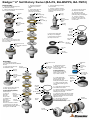
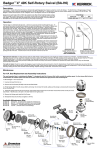
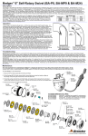
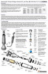
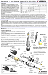
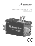
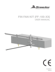
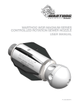
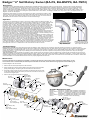
Badger TM 4" Self-Rotary Swivel (BA-P6, BA-BSPP6, BA-TM12)
Description:
The Badger™ Rotary Waterblast Nozzle was designed for waterblast cleaning of pipes as small as 4 inch with elbows. The BA-P6 has a 3/8 npt female inlet
connection and a maximum operating pressure of 15,000 psi (1035 bar). The BA-BSPP6 has a 3/8 BSPP female inlet connection and a maximum operating
pressure of 15,000 psi (1035 bar). The BA-TM12 has a 3/4 type M male inlet connection and a maximum operating pressure of 22,000 psi (1500 bar). Two
rotation speed ranges are available for each tool; a thick fluid is used for rotation speeds of 20 to 100 rpm, and a thinner fluid is used for rotation speeds of 75 to
250 rpm. The fluid in the swivel can be changed to provide either fast or slow rotation. The Badger™ heads have 1/8 npt ports; one at 15 degrees, two at 100
degrees, and two at 135 degrees.
Flow Range
Press. psi
R22
R16
Engraved on each head is R16 or R22; this number is the offset of the head that makes it rotate.
The flow range for each head is given in the table; nozzle sizes must be selected to fit within this
10,000
13-21
20-30
flow range. If the flow is less than the range shown, the tool will not rotate; if it is more than the
15,000
13-17
18-30
allowable the tool will rotate too fast and wear out the seals and bearings.
22,000 (1500 bar)
12-18
15-25
Operation:
The first step is to determine the jet sizes. Jet thrust is used to pull the tool through the pipe. An
estimate of the amount of pulling force required is useful and depends on the number of elbows and
any vertical climbs that must be made. On a horizontal run with no elbows, 1 pound of pull is
required for every ten feet. When climbing vertically, the pulling force must equal the weight of the
tool and the hose. Typically, larger jet sizes using 50 to 80 percent of the total flow are used in the
back ports. As little as 10 percent of the total flow is given to the front jet, because it pushes the
wrong direction and is only used to open up blockages. The remaining flow goes to the 100 degree
ports, which do help pull as well. Nozzles selected should be matched pairs, except the front jet.
When installing nozzles, we recommend using Parker Thread Mate and Teflon tape.
Because of the short length of the Badger, the tool turn can around in large pipes and come back at
the operator at a high rate of speed. If cleaning larger pipes, a rigid pipe "stinger" should be used
between the hose and the tool. It is recommended that the rigid length of the tool including hose end
is one and a half times the inside diameter of the pipe being cleaned.
Make sure there is an operator controlled dump in the system, operated by the person closest to the
cleaning job. Flush out the high pressure hoses before connecting the Badger. It is recommended
that the hose be marked a few feet from the end with a piece of tape so the operator knows when to
stop on the way back out. Position the tool in the pipe opening. Close the dump and slowly bring up
to pressure the first time to make sure no nozzles are plugged and the jet thrust is correct. The
Badger should begin to slowly rotate. Once operating pressure is reached, feed the tool into the pipe
to begin the cleaning job. Allow the jets time to do their work by feeding the hose out at a controlled
rate. When the work is complete and the tool is disconnected from the hose, blow out all water to
prolong the life of the tool. A small amount of oil can be blown into the tool as well.
1-1/2 times
pipe ID
rigid
"stinger"
IMPROPER USE:
Badger will turn around in
large diameter pipe
VERY DANGEROUS!
PROPER USE:
Badger with rigid "stinger"
to prevent turnaround, still
able to pass thru elbows
Troubleshooting:
High-pressure seal leak: The high pressure seal may leak initially at lower pressures, but should pop closed as pressure is increased. A continuous leak at
operating pressure from the weep holes indicates the need to replace the HP Seal and Seat. HP Seals wearing out too quickly can be an indication that the shaft bore
is worn, the HP Seat is installed upside-down, or the tool is over spinning. Over spinning is caused by low or contaminated viscous fluid, water in the fluid chamber
(replace shaft seals), or too much jet torque. Refilling the viscous fluid every 30-40 hours of operation is important for proper speed control. Only use StoneAge
recommended viscous fluid.
Tool will not rotate: Check the nozzles for plugging or wear (nozzles have to be removed to check for obstructions), Check that the nozzle sizes are correct for the
desired flow and that the desired flow matches the head flow range. Check that the nozzle sizes are installed in a balanced configuration. If the tool feels rough when
manually rotating the head, this indicates internal damage. Replace bearings, shaft seals, viscous fluid, and check the Inner and Outer Discs for flatness. These discs
can be deformed if tool is reassembled when discs are not properly aligned with BA 018 Pins.
Maintenance:
The most important item in maintaining the Badger™ is keeping the tool full of viscous fluid, which controls the rotation speed. As the
viscous fluid is lost or contaminated, the rotation speed of the tool will increase, which shortens the high pressure seal and bearing life.
To fill the Badger™ with viscous fluid:
BJ 026
Port Screw
(in Nut)
1. Remove the Port Screws (BJ 026) in the Nut and Head.
2. Fill the Syringe (BC 410) with viscous fluid by removing the end near the handle,
pulling out the plunger, and pouring the viscous fluid in from the back end.
BC 410
Syringe
3. Thread the syringe end into the port in the Head, and squeeze fresh viscous fluid
in until clean viscous fluid comes out the port in the Nut. Hold the tool so the port
in the Nut is the highest point.
4. Remove the Syringe and install the Port Screws.
BA 040-RXX
Head (15kpsi)
BJ 026
or
Port Screw
BA 240-RXX
Head (22kpsi)
BJ 026
Port Screw
(in Head)
BA 018
Pin
BA 006
Shaft Seal
BA 017
Retaining Ring
WG 008
O-Ring
Available Maintenance Kits:
BA
BA
BA
BA
BA
BA
600-x
600-TM12-x
602
610-x
610-TM12-x
612
BA 001 or
BA 001-BSPP6
Shaft (15kpsi)
RJ 012-TO
H.P. Seal (15kpsi)
or
RJ 012-KTO
BA 016
H.P. Seal (22kspi) Disc, Outer (3)
RJ 011
Seat, Brass (15K)
or
RJ 011-KC
Seat, Carbide (22kpsi)
Service Kit (Includes items needed for maintenance)
Service Kit (Includes items needed for maintenance)
Seal Kit (Includes parts needed for one seal change)
Overhaul Kit (Includes parts needed for tool rebuild)
Overhaul Kit (Includes parts needed for tool rebuild)
Tool Kit (Includes tools to aid assembly)
BA 002
Inlet Nut
BJ 026
Port Screw
SM 016
O-Ring (3)
BA 015
Disc, Inner (4)
BA 201
Shaft (22kpsi)
BA 018
Pin
UH 009
Bearing
BA 007
Shaft Seal
BA 030
Wear Ring
© 04/04/2014 StoneAge ,®All Rights Reserved
TM
Badger 4" Self-Rotary Swivel (BA-P6, BA-BSPP6, BA-TM12)
Disassembly:
1. Unscrew the Nut (BA 002) from
the Head (BA 040/240).
2. Pull the Shaft (BA 001/ BA 001-BSPP6/
BA 201) out of the Head.
BA 002
Nut
7. There is no need to remove
the Pins (BA 018) from the Shaft;
however, if they fall out do not
lose them.
5. Pull the Discs (BA 015,
BA 016) and O-Rings
(SM 016) off of the Shaft.
BA 017
Retaining Ring
10. Remove the Port Screw
(BJ 026) from the Head.
11. Remove the Shaft
Seal (BA 006) and O-Ring
(WG 008) if they are damaged.
BA 018
Pins (2)
BA 015
Disc, Inner (4)
BA 030
Wear Ring
BA 001/
BA 001-BSPP6/
BA 201
Shaft
6. Press the Bearing (UH 009)
off of the Shaft.
4. Remove the Retaining
Ring (BA 017) from the
Shaft.
12. There is no need to
remove the Pins (BA 018);
however, if they fall out, do
not lose them.
BA 001/
BA 001-BSPP6/
BA 201
Shaft
BA 016
Disc, Outer (3)
SM 016
O-Ring (3)
UH 009
Bearing
WG 008
O-Ring
BA 040/240
Head
BA 018
Pin (2)
8. Remove the Shaft Seal
(BA 007) if it is damaged.
BA 006
Shaft Seal
9. Remove the Port Screw
(BJ 026) from the Nut.
BA 040/240
Head
3. Remove the Seat
(RJ 011/RJ 011-KC) and H.P. Seal
(RJ 012-TO/RJ 012-KTO) from the
bore of the Shaft.
BA 007
Shaft Seal
RJ 011/RJ 011-KC
Seat
RJ 012-TO/RJ 012-KTO
H.P. Seal
BJ 026
Port Screw
BA 002
Nut
BJ 026
Port Screw
Assembly:
RJ 011/RJ 011-KC
Seat
1. Press Bearing (UH 009)
onto Shaft (BA 001/ BA 001-BSPP6/
BA 201).
2. Check that Pins (BA 018)
are installed in Shaft.
8. Apply grease to and
RJ 012-TO/ install the H.P. Seal
RJ 012-KTO (RJ 012-TO/RJ 012-KTO)
in bore of Shaft.
H.P. Seal
BA 017
Retaining Ring
BA 018
Pins (2)
RJ 012-TO/
RJ 012-KTO
H.P. Seal
10. Install Shaft Seals
(BA 007 and BA 006) in
the Nut (BA 002) and
Head (BA 040/240) as shown.
11. Place O-Ring (WG 008)
over threads and into groove
of Head.
WG 008
O-Ring
6. Repeat these
BA 015
steps, until
Inner Disc (4)
there are three
Outer Discs
and four Inner Discs on Shaft.
flat face
lip with spring up
UH 009
Bearing
4. Place an O-Ring (SM 016)
on top of this Disc, stretched
around the pins.
BA 016
5. Place an
Outer Disc (3)
Outer Disc
(BA 016)
SM 016
on top of this.
O-Ring (3)
RJ 011/
RJ 011-KC
Seat
9. Apply grease to the
flat face of the Seat
(RJ 011/RJ 011-KC) and
place in bore of Shaft, on
top of Seal, as shown.
BA 001/
BA 001-BSPP6/
BA 201
Shaft
3. Place an Inner Disc (BA 015)
on Shaft, aligning with pins.
chamfered
face
BA 007
Shaft Seal
BA 002
Nut
12. Check that the Pins (BA 018)
are installed in the Head.
BA 018
Pin (2)
13. Align the notches on the Outer Discs
with the pins in the Head; slide shaft
assembly into the Head.
lip with spring up
BA 006
Shaft Seal
14. Apply anti-seize to threads on Head;
install Wear Ring (BA 030) onto the Nut
(BA 002); thread the Nut onto the Head.
Tighten to 50 ft-lb.
15. Use syringe to fill the tool
with viscous fluid as shown
in the Maintenance Section; install
the Port Screws (BJ 026).
BA 040
Head
BJ 026
Port Screw
7. push down on top disc and
install the Retaining Ring (BA 017)
in the groove around Shaft.
BJ 026
Port Screw
BA 030
Wear Ring
© 04/04/2014 StoneAge®, All Rights Reserved