1
BROADCAST PROFANITY DELAY
BD500 software rev 3.0 document release 11
© 1995-2004 Eventide Inc. Little Ferry NJ USA
document p/n 141001 (All specifications and details subject to change without notice)
Contents
Chapter 1
Introducing the BD500 ..................................................................................... 1
Front Panel
Rear Panel
Audio Connections
2
3
4
Chapter 2 Operation ............................................................................................................. 5
Installation
Rack Mount
Connect AC and Turn On Power Switch
Level Meters
Connect Audio Inputs
Connect Audio Outputs
Understanding BD500 Profanity Delay Functions
REBUILD - Increase the delay gradually
RAMP TO ZERO - Decrease the delay gradually
WAIT FOR SAFE - Bring delay from 0 seconds to 4 seconds quickly
WAIT AND EXIT - Decrease the delay to 0 seconds quickly
SNEEZE - Edit the delay before a bad noise happens
DUMP - Edit the delay after a bad noise happens
Operation as a Profanity Delay
Modes
Functions and Features
Starting a Show Segment with REBUILD
Starting a Show Segment with WAIT FOR SAFE
Ending a Show Segment with RAMP TO ZERO
Ending a Show Segment with WAIT AND EXIT
DUMP Button
SNEEZE Button
Delay Amount Display
Operation as a Precision Fixed Delay
Controlling the Fixed Delay
Usage Notes
Chapter 3
5
5
5
5
6
6
7
7
7
7
7
7
7
8
8
8
8
9
9
9
10
10
10
11
11
11
Configuration ................................................................................................... 13
Password Protection
Restoring Factory Defaults
Table of Configuration Variables
Configurable Variables
13
13
14
16
Appendix A Optional AES/EBU Digital Audio .............................................................. 19
Connection
Configuration
Operation
Notes and Warnings for AES/EBU Operation
Remote Connector
19
19
19
20
21
Appendix B Basic Remote Control .................................................................................. 21
Appendix C Optional Remote Control/Signalling ........................................................ 23
Remote Connector
Configuring Optional Rear Panel Inputs and Outputs
Input Commands not available via front panel
23
24
24
Appendix D Optional Auxiliary Connector for Control Signal Delay .................... 27
Appendix E Optional RS-232 Control ............................................................................. 29
Appendix F Diagnostics ..................................................................................................... 33
Start-up Sequence
Startup Switches
Error Processing
Error Codes
33
34
34
35
Appendix G Specifications ................................................................................................. 45
Appendix H
Warranty Information ................................................................................ 47
Index ......................................................................................................................................... 49
Chapter 1 Introducing the BD500
The Eventide BD500 is designed to enable a broadcast licensee to prevent obscene and/or libelous material from
being transmitted over the air. It does this by automatically delaying program material by up to 20 seconds (optionally 40), allowing time for the monitoring operator to make the decision as to whether the material being
delayed fits into either category.
If objectionable material is heard, patented electronic circuitry allows all or a portion of the delayed audio to
be "dumped" and the program resumed without interruption. The delay time is increased automatically and gradually after the "dump" occurs. A remote control option allows an external relay to be attached which would prevent
uncontrolled sources, such as telephone callers, from being aired until the delay time is again long enough to provide protection.
The BD500 has some special functions to make it convenient to use: the WAIT AND EXIT function can be used
to synchronize to a network or live signal feed, and the RAMP TO ZERO function can be used to decrease the delay time to 0.00 gradually after it is no longer needed for a safety margin.
This manual discusses the use and operation of the BD500. All of the functions are presented explicitly, which
may make the manual seem somewhat forbidding. However, the unit is very simple to use and the apparent complexity portrayed in this manual is due to our desire to offer complete and accurate information.
BD500 Features:
• Up to 20 (40) seconds of stereo audio delay.
• Precision Fixed Delay mode which allows a front
• Allows multiple DUMP operations without expanel selectable delay between 2.25mS and 20.0
hausting the delay buffer. The DUMP function is
(40.0) seconds in steps of around 100uS.
adjustable and may be configured to delete an
• WAIT AND EXIT drops from full delay to 0.00 delay
amount between 1.0 seconds and 20.0 (40.0) secin 20 (40) seconds
onds.
• RAMP TO ZERO reduces the delay slowly using the
• SNEEZE function replaces microphone mute switch
same patented Eventide process as Rebuild
and allows short interruptions to be unnoticeable
• WAIT FOR SAFE function allows starting a show
• Patented Eventide Rebuild (catch-up) provides fast
with a safe amount of delay
recovery from a DUMP or SNEEZE while show is in • Numeric display shows amount of delay
progress
• Front panel configuration and display of audio input
• 24-bit Analog to Digital and Digital to Analog
and output attenuation
converters
• Remote control inputs to trigger SNEEZE and
• 32000 or 48000 samples per second sample rate
DUMP
• Relay contacts to signal safe condition and DUMP
button actuation
Optional Features:
• AES/EBU digital audio input and output
• RS-232 remote control
• Remote Control features including:
• 7 programmable remote button inputs on rear panel connector including mute,
station break insert and all front panel controls complete with permutations of
those controls.
• 4 programmable outputs to trigger relays, configurable to indicate different
timing conditions including status of all processes, bypass mode, and error
conditions.
• 8 delayed control signal lines used to delay external controls by the amount of the
audio delay
BD500 Broadcast Profanity Delay
©Eventide Inc. 1995-2004
doc release 11
Chapter 1 Introduction
Page 1
Front Panel
See Chapter 2 for in-depth explanation of the following controls, or look up individual terms in the Index.
The front panel buttons have indicator lights which
are lit when a function is available. A flashing light indicates that the function is running. Pressing a button
when it is flashing will cancel the function. The BYPASS button is illuminated when the unit is bypassed.
The DUMP button is illuminated when the unit has
enough delay to be safe. The CONFIGURATION button
and configuration mode are intended to be used by an
authorized operator only and thus its operation is intentionally less obvious. See Appendix A for configuration
mode information.
Since the BD500 can serve as a broadcast profanity
delay or as a precision fixed delay, many of the buttons
have dual purpose. In addition some buttons serve in
navigating the configuration menus (discussed in Chapter 3). All of the buttons are labeled for profanity delay
operation.
1
BYPASS button
Toggles the unit in and out of bypass. While bypassed
the LED is illuminated and the audio path through the
BD500 is bypassed through a relay. Pressing this button while bypassed will put the unit in-line, with zero
delay. This button is also used to exit from configuration mode.
2
CONFIGURE button
Enters configuration mode. See Chapter 3.
3
Level Meters
Two 10-segment LED bar graphs show channel 1 and
2 input levels. These graphs act as meters and may be
used to align the equipment such that adequate audio
levels are presented to the BD500.
4
WAIT FOR SAFE button
In profanity delay mode only, initiates or cancels the
wait for safe mode which is used to start a show with a
safe amount of delay.
4
2
5
WAIT AND EXIT button
In profanity delay mode only, initiates or cancels the
wait and exit process which exits quickly from delay.
6
REBUILD button
In profanity delay mode, starts or stops rebuilding the
delay. In precision fixed delay mode, decrements the
current delay-amount digit.
7
RAMP TO ZERO button
In profanity delay mode, instructs the unit to start or
stop ramping toward 0.00 delay. In precision fixed delay mode, this button increments the current
delay-amount digit.
8
SNEEZE button
If the unit is configured as a profanity delay, this button is used to cut off microphone audio. If delay is
greater than 0.00, the unit will reduce the delay while
SNEEZE is held. In configuration mode, this button sets
an individual value back to factory defaults. In precision delay mode, this button steps between digits of the
delay-amount.
9
3-Character Display
The 3-character LED shows delay-amount values, text
information, and configurable parameter values.
10 Delay-Amount Bar Graph
This 15-segment LED bar graph indicates current delay as a fraction of maximum delay or, in precision fixed
delay mode, indicates which digit of the delay value is
selected. This display is also used for visual cues during startup and configuration mode.
11 DUMP button
In profanity delay mode, deletes a segment of audio
in order to stop an undesirable audio segment from being transmitted. This button is illuminated only if the
unit is in profanity delay mode and then only if the
amount of delay meets or exceeds a preset safe amount.
WAIT FOR SAFE button
6
CONFIGURE button
REBUILD button
9
Delay Amount Numerical Display
DELAY AMOUNT
CLIP
Eventide
DUMP
MODEL BD500
BYPASS CONFIGURE
3
1
BYPASS button
Page 2
WAIT FOR
SAFE
LEVEL
Level Meters
WAIT AND
EXIT
REBUILD
7
5
RAMP TO
ZERO
BROADCAST DELAY
SNEEZE
Chapter 1 Introduction
MULTIPLE
DELAY DUMP
CAPABILITY
11 DUMP button
RAMP TO ZERO button
WAIT AND EXIT button
HIGH QUALITY
PATENTED
CATCH-UP
8
SNEEZE button
10 Delay Amount Bar Graph
BD500 Broadcast Profanity Delay
©Eventide Inc. 1995-2004
doc release 11
Rear Panel
4
RS-232 Connector (optional)
This is a female 9 pin DB9 connector supplied to connect a remote computer or terminal. The remote
computer or terminal can control all functions of the
BD500 including configuration. See Appendix E.
AC Power Connection/Control
The AC connection is an integrated connector/switch/
fuse holder to allow for greater reliability and safety.
1
AC Connector
IEC standard 3-prong connector. The center post is
chassis ground. When power is not connected, the unit
is bypassed, i.e., the audio inputs are connected to the
audio outputs through a relay.
5
Remote Connector
This is a female 15 pin DB15 connector for connection of external signalling (buttons, indicators,
telephone cut-off). See Appendices B and C.
2
Power Switch
This controls the AC power into the BD500. When the
power switch is off, the unit is bypassed.
6
Auxiliary Connector (optional)
This female 25-pin DB25 connector is used for delaying control signals by the delay amount. See Appendix
D.
3
Fuse Holder
1-Amp Slow Blow fuse. You should always replace it
with the correct value. This fuse interrupts the AC
power. Removal or destruction of this fuse will cause
all operation to stop and will cause the bypass relay to
close, connecting the XLR audio inputs to the XLR audio outputs. This does not guarantee that high voltage
will not be present in the unit. Always disconnect the
line cord from the AC connector before removing any
cover or panel.
Optional AES/EBU - Digital Audio In/Out
These optional connections are used to connect professional digital audio gear to the BD500. These cables
are differential with a shielded twisted pair.
7
Input data, XLR (optional)
The BD500's connector is female. Pin 1 is shield, 2
and 3 are differential.
8
Output data, XLR (optional)
The BD500's connector is male. Pin 1 is shield, 2 and
3 are differential.
Standard and Optional Remote Control and
Signalling
The BD500 has a standard remote control/signalling
output. This allows remoting of the dump and sneeze
functions and output of safe status (see Appendix B.)
The optional remote control card (see Appendix C) allows RS-232 remote control, relay/dry contact remote
control of front panel functions, relay drivers for external signals and lamps, and additional commands not
available from the front panel.
Analog Audio Inputs and Outputs
XLR differential audio connections for two input
channels and two output channels.
9 and 10 Channel 1 and 2 Outputs
Male XLR connectors.
11 and 12 Channel 1 and 2 Inputs
Female XLR connectors.
8
2
Power switch
5
7
Remote connector
AES/EBU
RS-232
1
50/60 Hz
4
RS-232 connector
6
Channel 1 output
AUDIO OUT
11 Channel 1 input
AUDIO IN
AUXILIARY
OUT
Auxiliary connector
IN
2
10 Channel 2 output
Fuse holder
BD500 Broadcast Profanity Delay
©Eventide Inc. 1995-2004
doc release 11
REMOTE
40W
AC connector
3
9
AES/EBU output
AC INPUT
100-250V AC
AES/EBU input
Chapter 1 Introduction
1
2
1
12 Channel 2 input
Page 3
Audio Connections
The BD500 provides XLR differential audio connections for two input channels and two output channels.
When bypassed, the audio pins of each input channel
are connected to the audio pins of each output channel using a four pole relay. The unit is automatically
bypassed when power is disconnected or turned off.
pin 2
pin 1
Analog Outputs
These male XLR connectors provide a differential
balanced audio output with a maximum level of +4dBm
and a nominal level of -20dBm. Pin 1 is grounded to
the case of the external XLR connector. Pin 2 is
+phase and pin 3 is –phase.
pin 3
Male XLR output, balanced
pin 2
pin 1
Each connection may also be used as an unbalanced
line. The BD500's XLR analog audio output connectors
are male. Pin 1 is grounded. Connect pin 2 to your
center conductor and leave pin 3 floating.
Analog Inputs
These female XLR connectors provide differential
balanced audio input. The input level has a maximum
value of +4dBm and nominal level of -20dBm, but an
internal attenuator increases the allowable level to
0dBm for nominal level and +24dBm for maximum.
Pin 1 is grounded. Pin 2 is +phase and pin 3 is –phase.
pin 3
Male XLR output, unbalanced
pin 1
pin 2
Even though the inputs of the BD500 are balanced,
you can still use them with an unbalanced line. The
BD500 XLR analog audio input connectors are female.
Pin 1 and pin 3 are grounded. Pin 2 is your audio signal.
pin 3
Female XLR input, balanced
pin 1
pin 2
pin 3
Female XLR input, unbalanced
Note: In the case of an XLR to XLR balanced line (i.e., differential) cable the
shield should be left disconnected on one
end (usually on the end connected to an instrument output). This helps to prevent
ground loops.
Page 4
Chapter 1 Introduction
BD500 Broadcast Profanity Delay
©Eventide Inc. 1995-2004
doc release 11
Chapter 2 Operation
This chapter describes how the BD500 is operated from the front panel using factory default configuration values. Optional remote control and configuration are described in later chapters and appendices.
Installation
Rack Mount
Normally the BD500 will be mounted in a standard 19-inch rack using washers to avoid damaging the front panel
overlay. The BD500 should be supported at the rear. The rack should be well ventilated and in a dry and dust
free environment so heat and moisture won't cause damage or degradation of performance.
Connect AC and Turn On Power Switch
Since the unit is electrically out of the audio path when in bypass mode, there is no reason to need access to
the rear panel power switch. The power-up mode is selected by the configuration and is the same regardless of
whether power is applied via the rear panel switch or via connecting the AC to an already switched-on unit. The
unit may be left powered on even if the rack's power is to be disconnected.
Immediately after the unit is switched on, the front panel will be fully illuminated. After several seconds, the
display will change to show TST. Just before the TST symbol is displayed the unit flashes the software version
number. The TST symbol is displayed for about 20 seconds while the unit performs a test of it's audio processing
hardware. After this time the unit will read the front panel buttons (and basic remote control inputs). If any
buttons (except DUMP and SNEEZE) are pressed when the test cycle ends, the unit will perform a special startup function (see Appendix F.) If no buttons are pressed, the unit will (by factory default) complete it's start-up.
The display will show --- and the BYPASS button should be illuminated. This combination of LEDs indicates
that the unit is powered on and in bypass mode.
Note that the BD500 can be configured to go immediately into on-line mode - see Chapter 3 for details.
Level Meters
There are two 10-segment LED bar graphs to display input level information. These graphs act as meters and
may be used to align the equipment so adequate audio levels are presented to the BD500. The meters indicate
the levels at the digital signal processor and are calibrated in decibels. The top LED is red. The next two are
yellow, and the bottom seven are green. The red LED is lit if the level reaches clipping. The remaining LEDs
indicate approximately -3dB, -6dB, -9dB, -12dB, -15dB, -18dB, -21dB, -24dB, -40dB.
CLIP
LEVEL
BD500 Broadcast Profanity Delay
©Eventide Inc. 1995-2004
doc release 11
Chapter 2 Operation
Page 5
Connect Audio Inputs
Connect audio inputs to the two female XLR connectors on the rear panel. It is safe to connect and disconnect
to the rear panel while the power is turned on. The inputs will probably come from a mixer board. Supply an
audio source at a level just less than clipping. The BD500's level meters indicate input level. Adjust your audio
source's output such that with a maximum input signal, the level meters have all of the green segments and both
of the yellow segments lit, but not the red segment.
If your audio source cannot be adjusted or does not have the range to achieve a low enough or high enough signal, you must adjust the BD500's input trim. The BD500 has up to 48dB of input trim which is controllable from
the front panel configuration mode. At the factory the input trim is set to unity gain. To add attenuation, press
the BYPASS button once or twice to turn on the BYPASS button's LED. Now press the CONFIGURATION button to enter configuration mode. Next press the RAMP TO ZERO button to go up through the configuration levels
until you reach 3AU. Press the WAIT AND EXIT button twice to go to the INP variable. Now press SNEEZE to
reset the parameter to the factory default 0DB. Press the REBUILD or RAMP TO ZERO buttons to step through
the attenuation values to achieve the desired amount of trim attenuation or gain. The available range is -31dB
(attenuation) and 17dB (gain). The trim adjustment affects the level meters as the adjustment is made. Note that
since the unit is bypassed (not processing audio), the output level is not affected by this adjustment. The level
meters will show the input levels as you make this adjustment.
Once the adjustment is complete, press the BYPASS button twice to place the unit in-line.
Connect Audio Outputs
The BD500 has an output level control, again operated from configuration mode, which can reduce the output
audio by up to 40dB. The factory default is no attenuation.
To adjust the audio output attenuation, repeat the above process except choose the OUT variable instead. The
range of this variable is -41 thru 0dB. Note that since the unit is bypassed (not processing audio), the output level
is not affected by this adjustment. The unit will have to be placed on-line (press BYPASS twice) to test the new
value.
AES/EBU
AC INPUT
RS-232
100-250V AC
Page 6
50/60 Hz
REMOTE
AUDIO OUT
AUDIO IN
AUXILIARY
OUT
40W
Chapter 2 Operation
IN
2
1
2
1
BD500 Broadcast Profanity Delay
©Eventide Inc. 1995-2004
doc release 11
Understanding BD500 Profanity Delay Functions
This section uses the tape recorder profanity delay as an analogy to describe how the Eventide digital broadcast delay behaves when used as a profanity delay. The digital broadcast delay can be likened to a tape recorder
with some new features. A basic tape recorder profanity delay would look like this:
When the delay is placed in line, the microphone (audio source) is connected to the record head while the transmitter is connected to the play head. This introduces a delay determined by the speed of the tape and the distance
between the tape heads.
In our analogy the speed of the tape is constant. The distance between the heads is
measured in seconds and there is enough room
between the tape heads for 20 (40) seconds of
delay. Factory default values are used whenever a time or duration is mentioned.
The Eventide system offers these features:
tape
direction
record
head
play
head
REBUILD - Increase the delay gradually
This feature allows the time between the play head and record head to be increased, in a subtle and transparent way. At the start the play head and record head overlap (no delay). The record head is slowly moved to the
left until 20 (40) seconds of delay exists. The Eventide patented rebuild process does this in about 240 seconds
without causing a pitch change in the audio. Rebuild is used to recover from a dump, without having to go to a
break.
RAMP TO ZERO - Decrease the delay gradually
This feature is similar to rebuild except that the record head is moved to the right, in a subtle and transparent
way, again taking a few minutes. When the record head reaches the play head, the unit is at live. Ramp to zero
is used to exit from delay when the call-in portion of a program is over.
WAIT FOR SAFE - Bring delay from 0 seconds to 4 seconds quickly
When the wait for safe process is started, the tape is bypassed so the transmitter gets live audio. The record
head is moved to the left by 4 seconds. After 4 seconds of recording, the transmitter is reconnected to the tape
delay. There is now a 4 second delay. Note, since the initial 4 second segment of audio will be repeated at the
play head, it is up to the user to prevent the live audio from going over the air. This feature is used to start a
show, coming from a network news feed, traffic report or other non-delayed program.
WAIT AND EXIT - Decrease the delay to 0 seconds quickly
This front panel feature is a method of quickly reducing the delay to 0.00 seconds. This process marks where
on the tape the record head was when wait and exit is started. When that piece of tape reaches the play head,
the record head is moved to the play head, decreasing the delay suddenly to 0.00 seconds. Use this command when
a call-in show needs delay but where a break to non-delayed operation is required.
SNEEZE - Edit the delay before a bad noise happens
This feature is used to stop the record process temporarily. While the SNEEZE button is pressed, the record
head moves toward the play head at the same speed as the tape, not recording any audio, until the SNEEZE button is released (at which point the record head stops), or until the record head reaches the play head, at which
point the silence is recorded to the tape.
DUMP - Edit the delay after a bad noise happens
DUMP is used to edit several seconds of audio from the delay. Pressing DUMP moves the record head 3 seconds toward the play head (or up to the play head, whichever is less). This causes the most recent 3 seconds of
audio from the microphone to be discarded.
See Appendix C for a description of optional Remote Control Connector features.
BD500 Broadcast Profanity Delay
©Eventide Inc. 1995-2004
doc release 11
Chapter 2 Operation
Page 7
Operation as a Profanity Delay
The BD500 may be used as a broadcast profanity delay. This is its primary function and factory default mode.
When power is first applied to the BD500, the unit's audio inputs and outputs are bypassed through a relay.
Pressing the BYPASS button places the unit in-line with 0.00 delay. If the audio levels are adjusted properly,
there should be no perceptible difference in audio levels. Note that since the BD500 uses true relay bypass, there
might be a slight click. The 3-digit display will now read 0.00 which indicates no delay. The red indicators on
several of the buttons will be lit, indicating which are valid choices. Which indicators are lit changes depending
on what state (or mode) the BD500 is in. Since the unit is at 0.00 delay and in-line it will be in live mode. The
following is a list of the few different modes the unit may be placed in:
Modes
• bypass and configuration - delay is set to 0.00 seconds, relays bypass the audio directly from input connectors
to output connectors.
• static - bypass relays are open (unit is in-line), delay is not changing.
• rebuild - bypass relays are open (unit is in-line), delay is slowly growing or is at maximum.
• ramp to zero - bypass relays are open (unit is in-line), delay is slowly reducing. Unit goes to static when it reaches
0.00 delay.
• wait for safe - bypass relays are open (unit is in-line), delay is filling with audio, but outputs are seeing input
audio without delay. Unit switches to rebuild mode when safe delay time is reached.
• sneeze - bypass relays are open (unit is in-line), input audio is not going into delay, but output audio is coming
from the delay. The delay length is reducing rapidly. When the SNEEZE button is released the unit will go
back to the previous mode.
• wait and exit - bypass relays are open (unit is in-line), input audio is not going into delay, but output audio is
coming from the delay. The delay length is reducing rapidly. The unit will go into static mode when it reaches
0.00 delay. The SNEEZE button is disabled.
Functions and Features
By default the BD500 is in bypass mode. Press the BYPASS button to put the BD500 in static mode. The delay
is now at 0.00 seconds and there should be no perceptible difference between bypass and static mode. After delay
build is initiated and until the delay is reduced back to 0.00, all audio must pass through the BD500 before going
to the transmitter.
Starting a Show Segment with REBUILD
This process is used to start a show in a simple manner. The guest or dial-in caller is enabled in less than two
minutes. The host customarily uses this period for an introduction or monologue.
As a show starts, the delay is set to 0.00. Pressing the REBUILD button starts a process by which the delay is
slowly increased. During the rebuild process the REBUILD button's indicator will flash.
In less than two minutes (depending on characteristics of input audio) the BD500 will have enough delay built
up to be 'safe' for a caller to be placed on the air. The DUMP button will light up to confirm this. The delay amount
will show 4.00 and increasing. If configured, a rear panel output line will allow an external relay to be closed,
enabling the phone line.
CLIP
BYPASS CONFIGURE
Page 8
LEVEL
WAIT FOR
SAFE
Chapter 2 Operation
WAIT AND
EXIT
REBUILD
RAMP TO
ZERO
BD500 Broadcast Profanity Delay
©Eventide Inc. 1995-2004
doc release 11
After a few minutes, the delay will reach maximum and the REBUILD button's indicator will turn off. The rebuild process is complete, but the delay remains in rebuild mode. This means that if SNEEZE or DUMP is used,
after the SNEEZE or DUMP button is released, the delay will automatically rebuild back to maximum.
Starting a Show Segment with WAIT FOR SAFE
This process is used to start a show rapidly. The guest or dial-in caller are enabled immediately after the studio goes on-the-air.
Before beginning, the transmitter is not getting its source from the BD500.
• The operator needs to know, or to set, the configuration value of safe time (default is 4.00 seconds.)
• At safe time (or more) seconds before the studio goes on-the-air the operator presses the WAIT FOR SAFE
button.
• The host begins talking immediately.
When the DUMP button illuminates:
• The WAIT FOR SAFE process has completed.
• The SAFE relay output is enabled.
• The engineer or host fades the output of the BD500 into the transmitter. (see note below)
• The host may begin taking dial-in callers.
The BD500 drops into rebuild mode and slowly completes building up to maximum delay.
Note: During the 4-second period that wait for safe is running and the WAIT FOR SAFE button's indicator is
flashing, the microphone audio is passed directly to the BD500 outputs. It is usually undesirable to have that
audio pass over the air. Use a mixer or other control to disable that audio until the show is scheduled to start.
Ending a Show Segment with RAMP TO ZERO
This process gradually reduces the delay and takes a variable amount of time up to a few minutes.
During the show, the BD500 would usually remain in rebuild mode at maximum delay. Whenever SNEEZE or
DUMP is used, the unit rebuilds back to maximum. To end the show, press RAMP TO ZERO. The delay will reduce in several minutes to 0.00 while the RAMP TO ZERO button's indicator flashes. During ramp to zero the
DUMP and SNEEZE buttons will continue to be available, but an eye should be kept on how much time is actually
still available to be dumped or sneezed away. To stop the ramp to zero process, press the RAMP TO ZERO button. The unit will go to static mode (delay not changing). The ramp to zero process may be resumed, or another
function may be started.
Once the ramp to zero process is complete, the unit will operate at zero delay (live).
Ending a Show Segment with WAIT AND EXIT
This process rapidly reduces the delay and takes the time displayed on the BD500's front panel indicator, i.e.
20 (40) seconds or less.
At the end of the show, after the last word is spoken, press the WAIT AND EXIT button. All of the audio delayed in the BD500 is played out in real time until the delay reaches 0.00. The WAIT AND EXIT button's indicator
flashes until the process is complete. Microphone audio is ignored by the BD500 during this process. When the
delay reaches 0.00, the unit goes into live mode in which input audio is passed directly to the outputs (i.e. on air).
DELAY AMOUNT
Eventide
DUMP
MODEL BD500
BROADCAST DELAY
SNEEZE
BD500 Broadcast Profanity Delay
©Eventide Inc. 1995-2004
doc release 11
Chapter 2 Operation
HIGH QUALITY
PATENTED
CATCH-UP
MULTIPLE
DELAY DUMP
CAPABILITY
Page 9
If the WAIT AND EXIT button is pressed erroneously, the process may be cancelled by pressing the WAIT AND
EXIT button again. The unit will go back to the delay it had before WAIT AND EXIT was pressed and will be
static (delay not changing).
DUMP Button
This button has several functions. The primary purpose of this button is to stop a profanity from going out over
the air. This button is illuminated when in-line with a safe amount of delay (specified by safe time). Here is a list
of modes and how the DUMP button works in each mode:
In rebuild or ramp to zero
DUMP causes the unit to delete several seconds (configurable) from the delay line including the audio information which has most recently been input to the delay line. The amount dumped is configurable and defaults to
3.00 seconds. When the DUMP button is pressed, the dump amount is subtracted from the current delay. If the
displayed delay is lower than the dump amount, the delay is reduced all the way to 0.00. While the DUMP button
is held down, the delay is held static. After DUMP is released, the unit continues with the previous mode. Note:
Even if the unit is no longer rebuilding, having already reached full delay, the unit will still return to rebuild
mode after DUMP is released.
In configuration or precision delay mode
DUMP causes the unit to exit the current mode and go into bypass mode.
In wait for safe
DUMP causes the unit to stop wait for safe, leaving the delay at 0 seconds.
In bypass, live, or wait and exit
DUMP has no function.
SNEEZE Button
This button is used to cover up an otherwise audible interruption to a program like a sneeze, cough, comment
to the caller or engineer, or other undesirable noise.
If the unit is in-line (not bypassed) in profanity delay mode and not in wait for safe or wait and exit mode, this
button will stop accepting input audio while it is held. The delayed audio will continue to be played out, reducing the delay amount. This would make the listener unaware that a mute occurred. If the delay reaches 0.00, or
starts at 0.00, the audio is muted. When SNEEZE is released, the unit goes back to the interrupted mode.
Delay Amount Display
The display consists of a bar graph and a 3-digit numerical display. The numerical portion shows the delay
amount in seconds with optional fractions of seconds. The factory default is to show seconds and hundredths of
seconds with the decimal point appropriately placed. The bar graph indicates what portion of maximum the unit
is delaying. For instance, if the unit is delaying at 3.50 seconds and the unit is configured to have a maximum of
8 seconds of delay, 6 of the 15 bar graph segments are lit.
The display is configurable to be blank, or to show 1, 2 or 3 digits of resolution of delay length. In bypass the
display will show the safe time.
Page 10
Chapter 2 Operation
BD500 Broadcast Profanity Delay
©Eventide Inc. 1995-2004
doc release 11
Operation as a Precision Fixed Delay
The BD500 may be used as a fixed stereo delay line, adjustable from 0.000 seconds to 20.000 (optionally 40.000)
seconds. Operation is straightforward, with several front panel buttons serving secondary duty as fixed delay
controls.
There are two ways to enter precision fixed delay mode. The easiest is to shut down the unit, then turn it back
on holding down the REBUILD button. After the TST mode completes you can choose between PFD or BD by using the SNEEZE button. Hit BYPASS to confirm selection and enter normal bypass mode.
The 2nd method is from configuration mode. Go into bypass mode. In bypass mode the display shows ---.
Press the CONFIGURE button. This puts the unit into configuration mode (display shows Cnf). Now press the
RAMP TO ZERO button. You are now at the "on-line" configuration level (display shows1on). Now press the WAIT
AND EXIT button twice. This moves across the on-line level to the run parameter. The display should now show
RUN.
PFD.
Now press the WAIT AND EXIT button repetitively (stepping through run modes) until the display shows
Press the BYPASS button to exit configuration mode. The display should show ---. Now press BYPASS to
put the unit in-line. The unit will be in fixed delay mode.
To return to profanity delay operation, press BYPASS, then CONFIGURE, then RAMP TO ZERO, then WAIT
AND EXIT twice. The display now shows RUN. Now press SNEEZE to return to the factory default setting of the
run parameter. Now press BYPASS to get out of configuration mode.
Controlling the Fixed Delay
In precision fixed delay mode the only operable buttons are titled BYPASS, REBUILD, RAMP TO ZERO, and
SNEEZE. The buttons behave as follows:
• BYPASS
takes the unit off-line Always valid.
• REBUILD
decrements selected delay digit. Valid if lit.
• RAMP TO ZERO
increments selected delay digit. Valid if lit.
• SNEEZE
selects one of 6 sets of digits to be adjusted. Always valid.
The bar graph below the three digit display indicates which of the three visible digits is selected for adjustment. The presence of the decimal point indicates that the three digits shown are the tens, ones, and tenths digits.
&07.0
editing the
first digit
10s of seconds
07.0 07.0 7.01
editing the
second digit
1s of seconds
editing the
third digit
1/10s of
seconds
editing the
fourth digit
1/100s of
seconds
012
314
editing the
fifth digit
1/1000s of
seconds
editing the
6th,7th and 8th
digits
microseconds
Press the SNEEZE button several times to step through the selected digits. The following illustration shows a
7.012314-second delay as the SNEEZE button is pressed five times. Press SNEEZE again to get back to the first
digit.
Usage Notes
The BD500 provides precision down to 4 samples in length. Thus at 48ksamples/sec you will see 4/48000 of a
second adjustment precision, or 83.3microseconds. Thus if you move the last 3 digits up and down you will see
changes that are around 83 per jump. At 32ksamples/sec you will see 125uS adjustment precision.
The minimum delay the BD500 will allow also depends on the sample rate used by the BD500. The minimum
will be less than 5 milliseconds.
The fixed delay writes data continuously into the 20 (40) second buffer. Changes in delay changes the position
of the play head, not the record head. That means that, if the delay length is adjusted by ear, the user doesn't
have to wait for new input audio to check the adjustment. While listening to an audio source, try adjusting the
seconds digit upward. It is easy to play the same 1-second piece of input audio eight times.
Note: When entering precision fixed delay mode from bypass the delay buffer is set to the previous value used
in the fixed delay. The delay line is erased, so the outputs will be silent for a brief time.
BD500 Broadcast Profanity Delay
©Eventide Inc. 1995-2004
doc release 11
Chapter 2 Operation
Page 11
Page 12
Chapter 2 Operation
BD500 Broadcast Profanity Delay
©Eventide Inc. 1995-2004
doc release 11
Chapter 3 Configuration
There are several adjustable values used by the broadcast delay. Configuration mode gives access to these values and allows them to be changed. This chapter covers the configurable variables that needed for the basic BD500.
Configuration of optional features is covered in the appendices.
Operation of the configuration mode is via the front panel buttons. All of the buttons are used to navigate
through a map of configuration variables. The WAIT FOR SAFE and WAIT AND EXIT buttons are used to move
left and right across the map. The REBUILD and RAMP TO ZERO buttons are used to move up and down through
the levels of the map and also to adjust the values of individual variables. The CONFIGURE button will move to
the left side of the map and if pressed while already on the left side, will move up through the levels. The SNEEZE
button is used to reset the selected variable to the factory default.
See the side-bar for a map of the configuration parameters. Note: Refer to Appendices for optional features.
Basic Operation Example
From bypass mode, press CONFIGURE. The display changes to show CNF . Press the RAMP TO
ZERO button to move up the map. The first press will
move to 1oN. The next will move to 2TI. Now press
the WAIT AND EXIT button a few times to move over
to the RT0 variable (ramp to zero time). Notice that
the SNEEZE button's LED is not lit. This means that
the RT0 variable is set to the factory default. Use the
RAMP TO ZERO button to change the value. Notice
that the SNEEZE button lights up. Press the
SNEEZE button to reset the parameter back to factory default.
Another Example
If the BYPASS button is not illuminated, press BYPASS. Next, press CONFIGURE. Once the display
shows
5ER ror
⇑
4PR ocessing
⇑
3AU dio
⇑
2TI me
⇒
⇒ oSC ⇒ PAU ⇒ QAL ⇒ SRC
⇒ SPr* ⇒
⇒
inP ⇒ oUt
DLA ⇒ SAF ⇒ REB ⇒ RT0 ⇒ DU
⇑
1oN line
⇒ PUP ⇒ RUN ⇒ DIS ⇒ PAS
⇑
CNF (config)
⇑
---(bypass)
* = AES/EBU option only
CNF, press the RAMP TO ZERO button. The
1oN. Now press the WAIT AND EXIT button twice.
display changes to
FLb* ⇒ REA ⇒ LOG ⇒ CLR
RUN. To check
The display changes to show LIV , indicating go
The display changes to
the run mode, press the REBUILD or RAMP TO ZERO button.
into live mode when exiting from bypass mode. To change the run mode, press the RAMP TO ZERO button. Use
the REBUILD and RAMP TO ZERO buttons to go up and down through the four possible values for the run parameter.
Press BYPASS to exit from configure mode and return to bypass mode. Any changes made will remain until
they are reconfigured.
Password Protection
If desired, configuration mode may be password protected. When protected, the user must press the CONFIGURE button and a single other button. The CONFIGURE button must be released last. When both buttons are
released the unit will go into configuration mode. If the unit is password protected, the display will show
P--
when the CONFIGURE button is pressed. Change or enable the password using the PAS configuration variable.
Restoring Factory Defaults
All factory defaults may be restored by holding down the CONFIGURE button while power is turned on. Keep
holding CONFIGURE down until the display shows "RELEASE". The " RELEASE" message text will be scrolled
marquee-fashion across the display. Once CONFIGURE is released, the display will show "FACTORY DEFAULTS".
Individual config values may be set to factory default by using the SNEEZE button while the value is selected.
The LED on the SNEEZE button is lit if the variable is not set to factory default.
BD500 Broadcast Profanity Delay
©Eventide Inc. 1995-2004
doc release 11
Chapter 3 Configuration
Page 13
Table of Configuration Variables
3 Character
Identifier
Note: Full descriptions of the selectable values are available in pages following this
table.
Description
CnF
PUP
RUN
Start of Config Mode
This selection has no configurable value. It
indicates entry into configuration mode
DIS
PAS
DLA
SAF
REB
RT0
DU
INP
OUT
OSC
Page 14
Units
Range of Values
Default
Value
Power-Up mode
This option selects whether unit goes into bypass
or in-line after power-up.
mode
Run Mode
This item selects the mode the unit goes into from
BYPASS. Select PFD to enable precision fixed
delay.
mode
LIV REB WFS PFD
LIV
Display Digits
This selects the number of digits used in profanity
delay mode.
# of digits
003 02 1 OFF
003
Password
Allows a password to be selected which would
limit access to the configuration mode.
button
No BYP WFS WAE REB
RT0 SNE DU
No
Delay Length
Maximum length the profanity delay will rebuild to.
seconds
1.0 1.5@ 2.0 ... &20.0
*8.0
seconds
1.0 1.5 @2.0 ... &20.0
4.0
Safe Time
Amount of time the profanity delay must have built
up in order to be SAFE. Controls the lighting of the
DUMP button and RCC outputs.
InL
BYP
BYP
Rebuild Time
Amount of time it will take to rebuild the delay from
0 seconds to maximum.
seconds
40
60 90 120 180
240 ... 720
240
Ramp To Zero Time
Amount of time it will take to perform a ramp to
zero from maximum to 0 seconds.
seconds
40
60 90 120 180
240 ... 720
240
Dump Amount
Number of seconds of audio that will be dumped
when the DUMP button is pressed.
seconds
1.0 1.5 @2.0 ... &20.0
#4.0
Input Attenuation
Amount of attenuation or gain used at the input of
the delay.
decibels
-31 -25 ... -2 -1 0DB
1 2 ... 16 17
0DB
Output Attenuation
Amount of attenuation used at the outputs of the
delay.
decibels
-41 -40 ... -2 -1
Oscillator and Pause, or Pause only
If Pause only is selected, rebuild or ramp to zero
progress is made only during periods of silence.
method
P
Chapter 3 Configuration
O P
0DB 0DB
O P
BD500 Broadcast Profanity Delay
©Eventide Inc. 1995-2004
doc release 11
3 Character
Identifier
Description
PAU
Pause Detection Level
Audio level (below maximum level) that is
recognized as silence.
QAL
Quality Requested
Requested performance quality. Lower numbers
have more artifacts but faster catchup.
Default
Value
Units
Range of Values
decibels
-46 -43 -40 -37
-34 -31 -28 -25
-22 -19
-40
percent
of
maximum
quality
0 10 20 30 40 50
60 70 80 90 100
70
channel
LEF L1 CEN R1 RIG
CEN
SRC
Source For Processor Input
Left/right mix of channels to be used in
determining the best times to do audio
processing during rebuild or ramp to zero.
REA
Fatal Error Reaction
Selects what should happen if a fatal error
condition develops. Options are hide the error
(usually restarts the unit) or halt and show error.
action
LOG
Display Error Log
Shows last three unique fatal error messages
error
code
CLR
Clear Error Log
Erases error log to 000s. Select YES to erase
log. Automatically falls back to NO.
action
HID
LNN
NO
SHO
LNN
LNN
YES
SHO
none
NO
Note: Configuration for optional features is discussed in the Appendices. For optional audio
features, see Appendix A. For optional remote
control features, see Appendix C.
BD500 Broadcast Profanity Delay
©Eventide Inc. 1995-2004
doc release 11
Chapter 3 Configuration
Page 15
Configurable Variables
CLR
Clear
This control erases the stored fatal error log. See
Appendix F.
DIS
Display Digits
This is the number of digits used to display the current delay amount. The BD500 has a three digit numeric
display used to show the delay amount in hundredths of
seconds. As the delay rebuilds or ramps to zero, the
hundredths digit can change rapidly enough to be distracting to the operator. By changing the number of
display digits to two, one or even none, this source of
distraction can be reduced greatly or eliminated. Since
the operator really only needs to know that the BD500
is in rebuild, and whether it is safe or not, the operator
may choose not to have the delay time presented in such
high resolution.
DLA
Delay Length
Delay length controls the maximum length of the
broadcast delay. This adjustment may select a delay
length of from 2.0 to 20.0 (40.0) seconds. Select a length
allowing the operator to dump multiple offending
phrases without impairing operator efficiency. A length
which is too short will not allow the operator enough
time to delete offending speech. A length which is too
long increases the amount of time required to exit from
the delay at the start of a break or end of a show.
DU
Dump Amount
This is the amount of time deleted from the delay
when the DUMP button is pressed. If the DUMP button is pressed when less than this amount of time is in
the delay, then the entire delay is deleted.
FLb
Fallback (AES/EBU option only)
If AES/EBU is selected and there is no digital audio
signal present, the unit will declare an out-of-lock condition. If the unit is in-line (not in bypass) and an
out-of-lock condition exists, the 3 digit display will flash.
If the FLB (fallback) variable is set to ANA (analog) then
the analog input audio will be used. The analog input
will be sampled at either 32000 or 48000, the sample rate
chosen being whichever of the two rates is closer to the
AES/EBU sample rate last received by the unit (or 32000
samples/second if no AES/EBU signal has been present
since power-up. The AES/EBU outputs will be active
and the rate will be the same as the input analog sample
rate. If the fallback variable is set to UNL (unlock) the
unit will mute the outputs until lock is regained.
Page 16
INP
Input Level
This controls an attenuator in the analog audio inputs
of the BD500. The maximum level is 17dB (17dB of
gain). The minimum level is -31dB (31dB of attenuation). While the meters immediately reflect changes to
the input level configuration variable, this control can
not affect levels seen at the analog outputs when bypassed.
LOG
Error Log
This variable shows the last three unique fatal error
messages. See Appendix F. 000 means no error recorded.
OSC
Oscillator (or Oscillator and Pause)
This parameter controls the technique used to perform the rebuild process (and ramp to zero process).
The default, oscillator and pause mode ( O P), performs
the fastest and best sounding rebuild for most kinds of
audio material. The alternative, pause only mode (P ),
produces a very high quality rebuild for audio comprised
solely of speech. This mode may rebuild slower than oscillator and pause mode under some circumstances and
is not recommended for use if the input signal contains
music, speech lacking pauses or audio containing constant high level background noise (car-phone audio or
wind noise).
OUT
Output Level
This controls attenuation in the analog and digital
audio outputs of the BD500. The maximum level is 0dB
(no attenuation). The minimum level is -41dB (41dB of
attenuation). This control does not affect output levels
when bypassed.
PAS
Password
Where some modicum of security is needed, this value
may be changed to the identifier of a front panel button.
If set, a user would have to go to BYPASS, press and
hold CONFIGURE, then press the selected additional
front panel button, in order to get into configuration
mode. A selection of NO indicates not set.
Chapter 3 Configuration
BD500 Broadcast Profanity Delay
©Eventide Inc. 1995-2004
doc release 11
PAU
Pause Level Adjustment
This value sets the threshold level used for the detection of pauses or silence. The default value has been
optimized for normal usage. It may be necessary to adjust this value if the level of ambient noise is high. Great
care should be taken when adjusting this value, as setting the threshold too high or too low may impair the
catchup operation. The effects of changing this setting
are best observed while rebuilding in pause only mode.
Generally, the lowest threshold level that allows for
rebuilding to occur should be used.
PUP
Power-Up mode
This controls whether the BD500 goes into bypass at
power-up or goes directly into processing. If iNL is selected, the unit will go directly to the in-line mode
selected by the RUN configuration variable.
QAL
Quality
This value governs the extent to which the configured
rebuild and ramp to zero time may be deviated from in
order to maintain high audio quality during rebuild. A
setting of 100 percent produces the best-sounding audio,
but allows the unit to deviate considerably from the
configured times. The extent of the actual deviation
depends upon the characteristics of the audio material
being processed. If strict adherence to the configured
time is required, the quality can be set to 0 percent. This
is not a recommended setting though, as it will tend to
produce poor audio quality during rebuild and ramp to
zero. The default quality values should suffice for normal usage.
20 second maximum delay. The actual time to complete
a rebuild may be different, depending on the audio content, and the settings of several other configuration
parameters.
This value should be set following suitable listening
tests, and can be reduced for shorter maximum delay
values, but should be increased for broadcasts with a
music content.
RT0
Ramp To Zero Time
The ramp to zero time is how long the BD500 will
need to go from maximum delay to 0.00 delay. This is
used to exit out of the delay gracefully. The ramp to zero
time affects the increase of speed of the audio material
passing through the delay and is measured in seconds.
The actual time to complete a ramp to zero may be
longer, depending on the audio content, and the settings
of other configuration parameters.
RUN
Run mode
This controls what mode the BD500 enters when leaving bypass mode. The selections are live, wait for safe,
rebuild, and precision fixed delay. Each of these modes
is described elsewhere in this chapter. The factory default is live.
SAF
Reaction
This variable chooses what remedy the BD500 will
use in case of a fatal error. The choices are SHO (show)
or HID (hide.) If SHO is chosen, an error message will
be displayed until the user presses the DUMP button or
removes power from the unit. If HID is chosen, the unit
will immediately reboot and start up again, after a short
delay, resuming the operation that was interrupted by
the error. In either case the error will be logged. See
Appendix F.
Safe Time
In many broadcasting situations a control output from
the broadcast delay will be used to control a telephone
connection or auxiliary microphone input. The control
input is only connected when enough delay has been
built up to allow the operator to delete offending vocals.
The delay length which must exist to allow the audio
connection is called the safe time. The safe time is related to the reaction time of the operator and the
complexity of what would be called offending speech.
Normally, the safe time is several seconds. Since wait
for safe is used to quickly build the delay to an amount
long enough to be safe, the safe time is also the time
value used by wait for safe. The value displayed while
in bypass is the safe time. This is important information
for users of the wait for safe feature. The DUMP button is illuminated only when the delay is larger than
safe time.
REB
Spr
REA
Rebuild Time
The rebuild time is how long the BD500 will need to
build from 0.00 delay to maximum delay. This is used
to start up the delay or recover from DUMP. The rebuild time affects the slowness of the audio material
passing through the delay and is measured in seconds.
The factory default is 240 seconds, or 4 minutes, for an
BD500 Broadcast Profanity Delay
©Eventide Inc. 1995-2004
doc release 11
Sample Rate (AES/EBU option only)
The SPR (sample rate) variable selects whether the
sample rate will be set by the AES/EBU input EbU or
will be set to one of the two fixed sample rates (32 48 ).
If the AES/EBU digital inputs are in use, this must be
set to EbU or these inputs will become unlocked.
Chapter 3 Configuration
Page 17
SRC
Source
This selects the amount of signal from each channel that will be fed into the signal processor for use in determining best time-to-process. If the unit is unable to pick good times-to-process, artifacts will be introduced into
the output audio. This value may be set to one of five values, from left to right, LEF L1 CEN R1 RIG . LEF (left)
indicates all of channel 1 and none of channel 2. RIG (right) indicates all channel 2. CEN (center) indicates an
even sample of both. L1 indicates a blend of mostly left (channel 1) and some right (channel 2). This adjustment does not affect the audio signal levels seen at the outputs.
If only one channel is used for input, set the source to that channel (LEF or riG ). If one channel is usually of
poorer quality (i.e., a telephone), give the other channel priority. For instance, if channel 1 is the local microphone and channel 2 is telephone, you might select L1. If channel 2 is a mix of local microphone and telephone,
and channel 1 is never used, select RIG.
6re
Optional Remote Functions
These are described Appendix C.
Page 18
Chapter 3 Configuration
BD500 Broadcast Profanity Delay
©Eventide Inc. 1995-2004
doc release 11
Appendix A Optional AES/EBU Digital Audio
The digital audio option replaces the standard BD500 analogonly audio board. It provides two channel analog audio input
and output, or two channel digital audio input and output using the AES/EBU format. This appendix describes the
connection, operation, and configuration of a BD500 with the
digital audio option.
pin 2
Connection
These cables are differential with a shielded twisted pair. For
short distances microphone cables can be used, but for longer
distances and permanent installation a digital grade twisted
pair cable is better.
Input data, XLR
The BD500's connector is female. Pin 1 is shield, 2 and 3 are
differential.
pin 1
pin 3
Male XLR output, balanced
Female XLR input, balanced
pin 1
Output data, XLR
The BD500's connector is male. Pin 1 is shield, 2 and 3 are
differential.
Configuration
pin 2
If the BD500 is equipped with the digital audio option the SPR
pin 3
and FLB variables will be available. The SPR (sample rate) variable selects whether the input will be AES/EBU or analog and Note: In the case of an XLR to XLR balanced line
if analog, which of two fixed sample rates will be used. The FLB
(i.e., differential) cable the shield should
variable selects what the unit does in the case that AES/EBU
be left disconnected on one end (usually on
is selected and the AES/EBU clock signal is bad.
the end connected to an instrument outThe sample rate variable is accessed by entering configuraput). This helps to prevent ground loops.
tion mode, stepping to the 3AU level using RAMP TO ZERO,
then stepping right to the SPR variable using WAIT AND EXIT.
Now use the REBUILD and RAMP TO ZERO buttons to choose a sample rate or AES/EBU as an input. The factory default for the SPR variable is 48, indicating 48,000 samples per second.
The fallback variable is accessed by entering configuration mode, stepping to the 5Er level using RAMP TO
ZERO, then stepping right to the FLB variable using WAIT AND EXIT. Now use the REBUILD and RAMP TO
ZERO buttons to choose analog or unlock.
Operation
The BD500 with digital audio option will support three input modes. These are:
• Analog input at 32000 samples per second;
• Analog input at 48000 samples per second;
• AES/EBU digital audio.
Regardless of what input mode is selected there will be audio on both AES/EBU and analog outputs. The sample
rate of the outputs will always be the same as the sample rate on the selected input. This applies both to the
analog audio operating mode, where the sample rate is selected by the SPR configuration variable, and to the digital
audio operating mode where the BD500 derives the sample rate from the input AES/EBU signal.
If AES/EBU is selected and there is no digital audio signal present, the unit will declare an out-of-lock condition. If the unit is in-line (not in bypass) and an out-of-lock condition exists, the 3 digit display will flash. If the
FLB (fallback) variable is set to ANA (fall back to analog) then the analog input audio will be used. The analog
input will be sampled at either 32000 or 48000, the sample rate chosen being whichever of the two rates is closer
to the AES/EBU sample rate last received by the unit (or 32000 samples/second if no AES/EBU signal has been
BD500 Broadcast Profanity Delay
©Eventide Inc. 1995-2004
doc release 11
Appendix A Optional AES/EBU Digital Audio
Page 19
present since power-up. The AES/EBU outputs will be active and the rate will be the same as the input analog
sample rate. If the fallback variable is set to UNL (unlock) the unit will mute the outputs.
Notes and Warnings for AES/EBU Operation
The input attenuation (iNP) configuration parameter does not change the audio levels for AES/EBU inputs. The
output attenuation (oUT) configuration parameter does affect AES/EBU outputs.
The AES/EBU source must be stable before putting the unit in-line. If your AES/EBU source's clock rate changes,
or if the AES/EBU is disconnected, or if the AES/EBU audio source is turned off while the BD500 is processing
audio (in-line and powered on), the BD500 may add artifacts to the audio, or may indicate a failure with an error
message.
The BD500's purpose is to store audio and play it back with a delay. If the rate of audio into the unit changes
while audio is stored, the audio played from the delay will change pitch. Thus if the AES/EBU source's sample
rate changes or stops altogether (cable is disconnected), the BD500 may play out audio with a significant pitch
shift! If the unit falls back from AES/EBU to analog input at a different sample rate there will be a pitch change
in the audio already delayed through the unit. Your digital system must be set very close to either 32000 or 48000
samples per second or using the fallback option in the BD500 will allow several seconds of pitch changed audio to
pass.
Page 20
Appendix A Optional AES/EBU Digital Audio
BD500 Broadcast Profanity Delay
©Eventide Inc. 1995-2004
doc release 11
Appendix B Basic Remote Control
The BD500 with the basic remote control feature has inputs for DUMP and SNEEZE and outputs to indicate
safe and dump.
pin 8
pin 1
pin
15
pin 9
Basic Rear Panel
Remote Control Connector
Female DB15
Remote Connector
The remote control connector is a female 15-pin DB15 on the rear panel.
Outputs
There are two conditional outputs available via the basic remote control outputs. These are safe, and DUMP.
The position of the dump push button is monitored by a set of double-throw contacts (S.P.D.T.). The safe condition (whether there is a safe amount of delay accumulated or not) is monitored by a further two sets of double-throw
contacts (D.P.D.T.).
Inputs
There are two input controls. These have identical function to the SNEEZE and DUMP buttons. The BD500
presents both contacts of the coil of an internal relay to the remote connector. The user provides five volts (nominal) across the contacts to close the relay and actuate the function, just as if the front panel button was pressed.
Pin-Outs
pin 1
dump-output, normally closed contact
pin 2
dump-output, common contact
pin 3
dump-output, normally open contact
pin 4
DUMP input, + side
pin 5
DUMP input, - side
pin 6
ground for 100mA 5V output.
pin 7
SNEEZE input, + side
pin 8
SNEEZE input, - side
pin 9
+ve source of 100mA @5V for use in triggering DUMP and SNEEZE only
pin 10 safe-output 1, normally closed contact
pin 11 safe-output 1, common contact
pin 12 safe-output 1, normally open contact
pin 13 safe-output 2, normally closed contact
pin 14 safe-output 2, common contact
pin 15 safe-output 2, normally open contact
Notes:
• Relay contacts are rated 30V, 1A maximum.
• DUMP input and SNEEZE input are relay coils and are rated 180ohm, 3.75V to 7.5V.
A simple circuit for triggering DUMP:
Connect your push-button across pins 9 and 4. Short pins 5 and 6.
BD500 Broadcast Profanity Delay
©Eventide Inc. 1995-2004
doc release 11
Appendix B Basic Remote Control
Page 21
Page 22
Appendix B Basic Remote Control
BD500 Broadcast Profanity Delay
©Eventide Inc. 1995-2004
doc release 11
Appendix C Optional Remote Control/Signalling
The Remote connector allows configurable inputs and outputs which may be assigned to control and monitor
front panel functions. This connector is optional. If this option is installed, there will be configuration items
available on configuration level 6RE as described on the following pages. Also see Appendix A.
Remote Connector
This is a 15-pin female DB15 connector which allows 7 inputs to the BD500 and 4 outputs. All front panel buttons are available for external control. In addition, outputs are provided on this connector to drive relays which
may be used for indicator lights and to enable audio signals.
pin 8
pin
15
pin 1
pin 9
Optional Rear Panel
Remote Control Connector
Female DB15
Outputs
The four outputs are open collector drivers. Each can sink 200mA, all outputs driven. Each of the four outputs
may be configured to reflect the operating mode of the unit (discussed later in this appendix).
Inputs
The seven inputs are used to trigger front panel switch functions and may be easily wired to remote switches.
pin 1
pin 2
pin 3
pin 4
pin 5
pin 6
pin 7
pin 8
pin 9
pin 10
pin 11
pin 12
pin 13
pin 14
pin 15
field contact supply output, 100mA max at a nominal voltage of 11.3v (see note) (pin 9 = ground)
remote input 1
remote input 3
remote input 5
remote input 7
remote output 2
remote output 4
reference supply input for open collector output drivers, max 25v @ 1.6amps (pin 15 = ground)
common ground for inputs
remote input 2
remote input 4
remote input 6
remote output 1
remote output 3
common ground for open collector driver outputs (pin 8 = voltage)
Notes:
• The field contact supply output is a BD500 supplied voltage to be used to trigger the BD500's remote inputs.
This would be used for one side of a dry contact (switch or relay), the other side of which would go to one of the
BD500's remote inputs. This supply could also be used as the pull-up voltage for low current relays.
• The reference supply input must equal the pull-up voltage for the open collector outputs. An inactive remote
output must be externally pulled up to this supply voltage. An active remote output is pulled to ground by the
BD500. The reference supply input is used for the internal clamp diodes.
• Remote inputs will be off if set to ground or floating (reference to pin 9), and on if a voltage greater than 4.5
volts is present. The input impedance is 3Kohms so the source must supply about 1mA at 4.5 volts DC or more
in order to signal an ON. The maximum input voltage is 25volts.
BD500 Broadcast Profanity Delay
©Eventide Inc. 1995-2004
doc release 11
Appendix C Optional Remote Control
Page 23
Configuring Optional Rear Panel Inputs and Outputs
The remote control feature supports up to 7 inputs and 4 outputs which may be connected to switches and relays. Using configuration mode, the inputs may be used to operate all of the front panel button functions and a
few other functions as well. The assignment of the input lines to various commands is handled by the configuration mode. The remote outputs are also configurable to signal many different conditions in the BD500.
If the remote conotrol option is installed the configuration mode will have an additional level of configurable
items. This will be the 6RE level. To access this level go into configuration mode as described in chapter 3 and
move up the levels using the RAMP TO ZERO button until the 6RE level is reached. Now use the WAIT AND
EXIT and WAIT FOR SAFE buttons to navigate across the level. You will have the option of configuring the seven
input signals and the four output signals.
Each configurable input may be configurated to actuate one of several commands in the BD500. Similarly the
outputs are configurable to be actuated when one of several conditions occurs in the BD500.
Note: U is represented by U, W is represented by W, and V is represented by V.
Input Signals
The commands the inputs may be configured to are:
• OFF Off
causes input signal to have no function (factory default)
• BYP Bypass
• CNF Configure
same as the BYPASS button
same as the CONFIGURE button
• WFS Wait For Safe
same as the WAIT FOR SAFE button
• WAE Wait And Exit
• REB Rebuild
same as the WAIT AND EXIT button
same as the REBUILD button (used in precision fixed delay as decrement)
• RT0 Ramp To Zero
same as the RAMP TO ZERO button (used in precision fixed delay as increment)
• SNE Sneeze
same as the SNEEZE button (used in precision fixed delay as digit select)
• DU
same as the DUMP button
Dump
• LIV Live
• STA Static
cancel all commands and go to 0.00 delay
cancel all commands and hold at current delay
• FUL Full Delay
cancel all commands and go to full delay
momentary audio output mute.
• MUT Mute
• SBI Station Break Insert mutes the outputs while save the audio into the buffer. When the buffer reaches
4 seconds this mode ends and the unit goes into ramp to zero mode.
• RTB Ramp To Bypass
dump and then force rebuild mode.
• D-R Dump into Rebuild
• E-R Wait and Exit/Rebuild Toggle between wait&exit and rebuild
• 0-R Ramp to Zero/Rebuild
Toggle between ramp to zero and rebuild
Input Explainations
The Bypass, Configure, Wait For Safe, Wait And Exit, Rebuild, Ramp To Zero, Sneeze, and Dump selections
are identical in function to the front panel buttons. A closure on one of these inputs will duplicate the front panel
operations. Only if a button on the front panel is actually depressed will these commands be overridden. These
closures also perform the same operation in precisision fixed delay mode as the front panel buttons of the same
name.
There are additional functions available via these inputs that are not available on the front panel. These are
described below.
Input Commands not available via front panel
Static
This command cancels the current function. This puts the unit in a mode that is the
same as if the RAMP TO ZERO button were pressed while the unit was ramping to zero.
This command has no function in precision fixed delay mode.
Page 24
Appendix C Optional Remote Control
BD500 Broadcast Profanity Delay
©Eventide Inc. 1995-2004
doc release 11
Full Delay
Mute
Station Break Insert
This commands the unit into static mode at full delay. This command has no function in
precision fixed delay mode.
This command will mute the output audio while the closure exists. Note that the unit
will go into mute mode during this time so any button illumination or output signal that
reports on a particular mode will report mute mode instead of the previous mode, even
if the BD500 is still performing the previous function. When mute is no longer asserted
the unit returns to the previous mode.
mutes the outputs while save the audio into the buffer. When the buffer reaches 4
seconds this mode ends and the unit goes into ramp to zero mode.
These three special Remote Control features are supplied to allow maximum control with the
minimum number of buttons.
Ramp To Bypass
Dump into Rebuild
Wait and Exit/Rebuild
Ramp to Zero/Rebuild
performs a ramp to zero but when the unit reaches 0 delay it goes directly into bypass.
performs a dump and then goes into rebuild, regardless of the previous mode. This
operation has no affect in precision fixed delay mode. If the delay is already 0, then the
unit still goes into rebuild.
If the unit is at zero delay, this command puts it into rebuild mode. If the unit is not at
zero delay, this command puts it into wait and exit mode.
If the unit is at zero delay, the unit is placed into rebuild mode. If the unit is not at zero
delay, the unit is put into ramp to zero.
Output Signals
The output signals may be configured to:
always high impedance (factory default)
• OFF Off
On
• ON
• BYP Bypass
always a closure to ground
closure to ground when bypassed, high impedance if in-line
• LIV Live
closure to ground when in-line and at 0.00 delay
• WFS Wait For Safe
• FUL Full Delay
closure to ground when doing wait for safe
closure to ground when at full delay, high impedance when delay < full
• SAF Safe
closure to ground when > than safe time, high impedance when < safe time
• WAE Wait And Exit
• RT0 Ramp To Zero
closure to ground when doing wait and exit
closure to ground when doing ramp to zero
• RBM Rebuild Mode
closure to ground when in rebuild mode (doing rebuild, or at max). Note: During
sneeze or mute, the unit will still be rebuilding and will return to rebuilding
when mute or sneeze is released but this output signal will be off.
closure to ground when doing rebuild (not at max delay). Note: During sneeze
or mute, the unit will still be in rebuild mode and will return to rebuilding when
mute or sneeze is released but this output signal will be off.
• REB Rebuild
• MUT Mute
• DMP Dump
closure to ground when mute is being operated.
closure to ground when dump is being operated.
• UNL Unlock
closure to ground when AES/EBU is selected as an input but no digital audio
signal is present on the inputs. (requires optional digital audio card)
• SBI Station Break Insert closure to ground when a station break insert is in progress.
closure to ground indicates the unit is in run-time with the rear panel inputs
• RDY Ready
ready to accept a command to adjust the delay length or go in or out of BYPASS.
• ERR Error
• AIO All Is OK
closure to ground indicates there is an error message in the Error Log
closure to ground indicates there are no errors in the Error Log and the unit is
in run-time with the rear panel inputs are ready to accept a command to adjust
the delay length or go in or out of BYPASS.
BD500 Broadcast Profanity Delay
©Eventide Inc. 1995-2004
doc release 11
Appendix C Optional Remote Control
Page 25
Example, Wiring an External DUMP Button and Caller Cutoff Relay
This example connects a remote DUMP button to input 1 and connects a caller cutoff relay to output 1 and then
configures the port to enable the external connections.
Hardware
The first step is wiring the hardware. This section should be taken as an example only and proper design of the
circuits described herein should be performed only by qualified personnel.
Following the diagram shown below, connect a relay across pins 1 and 6 of a user supplied DB15 male connector. Additionally, connect pin 1 to pin 8. This will be the remote caller cutoff relay. The relay should have a coil
resistance of about 1000 ohms with a pickup voltage of 12 volts, and a dropout voltage of 10 volts or less. The
relay's contacts should have current, voltage, and leakage ratings to suit your system requirements. The relay
coil will actuate when the BD500 is safe.
Connect your remote DUMP switch across pins 1 and 2. The switch should be normally open.
to telephone and
telephone line
Illustration of the back side of a user
supplied male DB15 connector
pin 8
pin 1
pin 9
pin 15
Configuration
This sequence will enable the remote DUMP button input and the caller cutoff relay.
• Make sure unit is in bypass mode (BYPASS button illuminated)
• Press the CONFIGURE button to enter config mode. The display shows
CNF.
You are now in configuration mode
• Press the RAMP TO ZERO button six times so the display shows
6RE.
You are at the remote control configuration level
• Press the WAIT AND EXIT button once to move to the first input item. The display shows
IN1.
You are configuring remote input 1
• Press the RAMP TO ZERO button repetitively until the display shows
DU.
You have set remote input 1 to emulate the DUMP button when triggered.
• Press the WAIT AND EXIT button repetitively until the display shows
OU1.
You are configuring remote output 1
• Press the RAMP TO ZERO button repetitively until the display shows
SAF.
You have set remote output 1 to be a closure to ground when the unit is safe
• Press the BYPASS button so the BYPASS button illuminates
Configuration is complete; you are back in bypass mode
Testing
Press the BYPASS button to put the unit in-line. Now press WAIT FOR SAFE. The unit will quickly attain the
safe condition. When the BD500's front panel DUMP button illuminates, the relay should close. Once this happens, press your new remote DUMP button. The delay should be reduced by the dump amount.
Page 26
Appendix C Optional Remote Control
BD500 Broadcast Profanity Delay
©Eventide Inc. 1995-2004
doc release 11
Appendix D Optional Auxiliary Connector
for Control Signal Delay
Auxiliary Connector
This is a 25-pin female DB25 connector which is implemented as an eight channel control signal delay line. Signals presented to the auxiliary inputs are delayed by the displayed delay amount and driven to the auxiliary
outputs. These signals are read at 2mS intervals and are assumed to be high/low values such as those produced
by switches or relay contacts - they are not suitable for signal or control tones.
Outputs
The eight outputs are open collector drivers. Each can sink 200mA, all outputs driven.
Inputs
pin 1
field contact supply output, 100mA max at
a nominal voltage of 11.3v (see note) (pin 14 is
ground).
pin 2
auxiliary input 1
pin 3
auxiliary input 3
pin 4
auxiliary input 5
pin 5
auxiliary input 7
pin 6
no connection
pin 7
no connection
pin 8
no connection
pin 9
auxiliary output 2
pin 10 auxiliary output 4
pin 11 auxiliary output 6
pin 12 auxiliary output 8
pin 13 reference supply input for open collector output
drivers, max 25v (pin 25 = ground)
pin 14 common ground for inputs
pin 15 auxiliary input 2
pin 16 auxiliary input 4
pin 17 auxiliary input 6
pin 18 auxiliary input 8
pin 19 no connection
pin 20 no connection
pin 21 auxiliary output 1
pin 22 auxiliary output 3
pin 23 auxiliary output 5
pin 24 auxiliary output 7
pin 25 common ground for open collector driver outputs
(pin 13 is + voltage)
Notes:
• The field contact supply output is a BD500 supplied voltage to be used to trigger the BD500's auxiliary inputs.
This would be used for one side of a dry contact (switch or relay), the other side of which would go to one of the
BD500's auxiliary inputs. This supply could also be used as the pull-up voltage for low current relays. This is
a separate supply from the remote port supply.
• The reference supply input must be the highest +ve voltage applied to the open collector outputs and must be
less than 25V. This input is used for internal clamp diodes protecting against voltage spikes generated by relays, etc.
• An active auxiliary output is pulled to ground by the BD500 and can sink up to 200mA. The load for the output
(relay, lamp, etc) should be connected to the reference supply (or a lower voltage).
• Auxiliary inputs will be off if set to ground or floating, and on if a voltage greater than 4.5 volts is present. The
input impedance is 3Kohms so the source must supply about 1mA at 4.5 volts DC or more in order to signal an
ON. The maximum input voltage is 25volts.
BD500 Broadcast Profanity Delay
©Eventide Inc. 1995-2004
doc release 11
Appendix D Optional Auxiliary Port
Page 27
Page 28
Appendix D Optional Auxiliary Port
BD500 Broadcast Profanity Delay
©Eventide Inc. 1995-2004
doc release 11
Appendix E Optional RS-232 Control
An option-card equipped BD500 can be completely configured and operated from a personal computer or
user-supplied custom control system. The female 9 pin RS-232 connector on the rear panel is the mate for a typical office-type desktop computer. The BD500 operates as Data Communication Equipment (DCE) - the same as a
modem. A straight through cable may be used to connect the BD500 to a unit operating as Data Terminal Equipment (DCE), such as a personal computer.
The characteristics of the RS-232 connection are 9600 baud, 8 bits, 1 stop bit and no parity (9600, 8, 1, none).
The following table is the pin number, label, and direction relative to the BD500. The label is the same as used
by the terminal or PC that will be connected to the BD500. Since the BD500 is DCE, the labels and direction are
opposite in meaning to those of the DTE definitions.
Pin 1
Pin 2
Pin 3
Pin 4
Pin 5
Pin 6
Pin 7
Pin 8
Pin 9
DCD (out)
RxData (out)
TxData (in)
DTR (in)
Gnd
DSR (out)
RTS (in)
CTS (out)
RI (out)
pin 5
pin 9
pin 1
pin 6
Optional Rear Panel
Serial RS-232 Connector
Female DB9
The BD500 only sends messages as a response to a poll from a host computer. The host computer must not send
a message unless it has received a > character (hex 3E) or unless it has not heard from the BD500 in 100mS. An
overflow or bad message will be answered with a E> (hex 45, 3E).
Protocol
The following page has a list of single byte commands which are available to the host computer. The table lists
the response generated by the BD500. All commands will generate a response. !> indicates command processed,
X> indicates command not valid at this time, E> indicates serial port error or unrecognized command, U> indicates front panel button was held down (or rear panel input signal is simulating a button) and message was ignored.
Redundant commands will be answered with a good response. End of sneeze and dump will put the unit back in
the mode it was in before the sneeze or dump started. All transmitted and received bytes are between 30hex and
5Fhex.
Protocol notes
The unit is allowed to send an error message (E>) at any time. Any interrupted message is terminated when
the error message is sent, so the > character will be permission for the external device to send a new command.
The unit always gives a U> error message if a message is sent to the unit while a button is held down. The only
way 'request mode' will respond with S <sneeze> is when the sneeze was instigated by RS-232 remote control.
A change in either the DLA or RUN configuration variables will have no effect until the unit goes from bypass
to in-line.
The BD500 does not use the hardware control lines. Only RxData, TxData and Gnd are necessary.
BD500 Broadcast Profanity Delay
©Eventide Inc. 1995-2004
doc release 11
Appendix E Optional RS-232 Control
Page 29
RS-232 Protocol
requests static at 0 delay ............ puts the unit in-line. If broadcast delay, puts the unit at 0 delay. If PFD goes to last delay.
increments PFD digit .................... Note: PFD must be entered via configuration change to the run mode parameter (run).
decrements PFD digit
selects PFD digit
starts mute .................................... use the K command to unmute. Works in PFD and broadcast delay.
initiates pause .............................. use in broadcast delay from live to insert station identification.
initiates ramp to bypass ............... in broadcast delay performs ramp to zero and then automatically switches to bypass.
initiates wait and exit
switches to bypass mode
requests config values ................ shows current settings of each of the config values. This long response includes multiple
records. Each record consists of a 3 byte config variable name, followed by an ASCII equal
sign (=), followed by a 3 byte config value, followed by hex 0D (carriage return). After the last
record will be an a >. None of the 3 byte values contain >. The records correspond to configuration items described in chapter 3 and are all ASCII characters of the set 0 through 9, A
through Z, space and dash. Records which have no configurable values will have "NA " (3
bytes) instead of the 3 byte value.
D performs a dump
E entire config table ........................ dump entire config table, all variables, all available values. This long response includes multiple records. Each record consists of a 3 byte config variable name, followed by an ASCII equal
sign (=), followed by one or more 3 byte strings, each containing config values, separated by
spaces, followed by a space and then hex 0D (carriage return). After the last record will be a
>. None of the 3 byte values contain >. The records correspond to configuration items described in Chapter 3 and are all ASCII characters of the set 0 through 9, A through Z, space
and dash. Records which have no configurable values will have "NA " (2 bytes and a space)
instead of 3 byte strings.
F go to static at full delay
G go to next config variable ............ steps to next config variable. Responds with normal !>. Use X to request current config variable name and value. See also C, E, J, N, Q, V, X, and Y commands.
H go to static at current delay ........ If in broadcast delay mode goes to in-line, static and at full delay.
I
requests debugging info .............. responds with machine state name and current delay amount. This is for debugging only, may
change, and is redundant with the M and T commands.
J store config variable .................... write the current config variable's value into permanent storage.
K ends a sneeze
L requests levels ............................. three character response is left channel level followed by right channel level and terminated
with >. Levels are reported using one digit ASCII hex of range 0 through 9, and A. Example:
25> is left channel level of 2, right channel of 5.
M requests mode ............................. response is three characters of the form !n> where n is the current mode. Modes are A <wait
and exit>, B <bypass>, D <dump>, G <gapless>, H <static>, L <live>, M <mute>, P <precision
fixed delay>, R <rebuild>, S <sneeze>, W <wait for safe>, Z <ramp to zero>. Note: zero delay
and maximum delay are not modes; if the unit reaches maximum delay while in rebuild mode,
the unit remains in rebuild mode though if it reaches zero delay it switches to static mode.
N next config value .......................... steps the current config variable to the next value. When the maximum value is reached, the
next will be the minimum. Responds with normal "!>". This command does not change the stored
config value, only the used value. Use the J command to save the current config variable.
Use X to request current config variable name and value. See also G command.
P requests PFD delay ..................... response is 7 or 8 digit decimal ASCII value of delay in microseconds, followed by position indicator (1, 2, 3,4,5 or 6), followed by >. Note: This does not change the mode to PFD.
Q resets config stepping ................. points at start of config mode. Used with C, E, G, J, N and V, X, and Y commands to make
configuration changes to the BD500.
R initiates rebuild
S starts a sneeze ............................ See K command for end-sneeze.
T requests current delay ................ response is 3 or 4 digit decimal ASCII value of delay in 10s of milliseconds, followed by >.
U requests current delay/hex .......... send delay amount in 10s of mS as hexadecimal using 3 chars of ASCII hex followed by H>.
V Eventide Factory Defaults ........... request factory defaults for all config variables. Note: Allow 400mS before "!>"
W initiates wait for safe .................... Note: when the unit reaches safe, it will switch to rebuild mode.
X examine config ............................. gives current config variable and value. Responds with an 8-character message consisting
of a three character config variable identifier, an ASCII equal sign (=), the three character value
of the config variable, and a >. See G, N and Q.
Y first value ...................................... sets the current config variable to the first value. Useful for making automated configuration
changes. See C, E, G, J, N, Q, V and X commands.
Z initiates ramp to zero
0
1
2
3
5
6
7
A
B
C
Page 30
Appendix E Optional RS-232 Control
BD500 Broadcast Profanity Delay
©Eventide Inc. 1995-2004
doc release 11
RS-232 Command Examples and Tables
This section offers organizational information and help information for using RS-232 commands.
Broadcast Delay Commands
These are the broadcast delay commands. Note that
some commands will work in broadcast delay mode but
are not commonly used are left out of this section.
L
M
T
U
0
H
B
W
A
Z
R
S
K
D
requests levels
requests mode
requests current delay
requests current delay/hex
go to static at 0 delay
go to static at current delay
switches to bypass mode
initiates wait for safe
initiates wait and exit
initiates ramp to zero
initiates rebuild
starts a sneeze
ends a sneeze
performs a dump
,
,
, and
variables that, when
are the
changed, might cause bad artifacts in the audio.
Changes to those variables are not used by the BD500
audio processor until the unit goes into and out of 0 delay or bypass.
M
B
0
C
E
G
J
N
Q
V
X
Y
Precision Fixed Delay Commands
These are the fixed delay commands.
L
B
0
1
2
3
P
requests levels
switches to bypass mode
switches from bypass to in-line
increments PFD digit
decrements PFD digit
selects PFD digit
requests PFD delay value
Configuration Mode Commands
The RS-232 configuration commands step through the
configuration variables in much the same way the front
panel does. Use the G command to step to the next variable. Use the N command to step through values for a
single variable.
4.56
LEVEL
WAIT FOR
SAFE
WAIT AND
EXIT
REBUILD
RAMP TO
ZERO
BD500 Broadcast Profanity Delay
©Eventide Inc. 1995-2004
doc release 11
Note that you must wait for a prompt before sending
each character.
To change the rebuild rate from whatever it happens
to be to 240, you can send Q G G G G Y N N N N N J.
Spaces are not used. This sequence says: go to first variable, then step through the variables to the REB
variable, then set it to the first value, then step through
to the 6th value which is 240, then save it.
In order to change the full delay amount the unit has
to be placed into bypass. This sequence will change the
maximum delay to 4 seconds and put the unit back in
line. Q G G G Y N N N N J B 0 Note that if you issue
the B command while the unit is already bypassed, you
will get an error message. Your sequence may expect
the error message and ignore it.
DELAY AMOUNT
CLIP
CONFIGURE
requests mode
switches to bypass mode
switches from bypass to in-line
dump values for all config variables
dump possible values for all variables
go to next config variable
store current config variable in nvRAM
next value for this variable
back to first variable
Eventide Factory Defaults
examine current variable
first value for this variable
Example configuration operations
The RS-232 commands allow the front panel of the
BD500 to be completely replicated in function (and in
form) by a remote device. A computer with a terminal
emulator may use these commands to prove that all of
the information and control is available. Use the T, M
and P commands to watch modes and delays change as
commands are issued.
BYPASS
Variable are not saved into nonvolatile memory immediately as is the case with the front panel configuration
mode. You must use the J command to implicitly save
a new value. Non-saved values are lost if the unit is
powered off. Most values will, however, be used by the
BD500 immediately after changed. Exceptions to this
DUMP
SNEEZE
Appendix E Optional RS-232 Control
Page 31
Page 32
Appendix E Optional RS-232 Control
BD500 Broadcast Profanity Delay
©Eventide Inc. 1995-2004
doc release 11
Appendix F Diagnostics
The BD500 has software features designed to aid debugging the system hardware. Some of these features
may be used to assist in analyzing end-user setup problems or in diagnosing user or off site technician
serviceable components. This section includes a breakdown of different operations that the broadcast delay
does during power-up and while changing operation
modes. In addition, the 'hidden' start-up modes and
system hardware failure messages are described.
Disclaimer: This information is correct at the time of
this manual's publication (before release of version 2.5
of the BD500 software.)
•
•
•
•
•
•
Start-up Sequence
•
•
•
•
•
•
•
•
•
•
•
•
•
•
•
•
•
•
•
•
•
Reset front panel (turns all lights on)
Turn off DS113 motherboard LED, then flash it on,
then off again
Turn off option board Remote Control Connector and
Auxiliary Connector outputs
Turn on DS113
Cycle through the seven motherboard status LEDs
from #2-0 to #2-6
Turn off DS113
Test the firmware ROMs - if fail, flash motherboard
status LED #2-0 indefinitely - if pass, light motherboard status LED #2-0 indefinitely, then scan the rest
of the LEDs once - the front panel will stay all-lightson indefinitely if failure
Test the motherboard RAM - if fail, flash motherboard
status LED #2-1 indefinitely - if pass, light motherboard status LED #2-1 indefinitely, then scan the rest
of the LEDs once - the front panel will stay all-lightson indefinitely if failure
Initialize motherboard RAM
Flash motherboard status LEDs #2-4, #2-5 and #2-6
three times quickly, leaving them off
Turn on DS113 motherboard LED
Declare that we are not in run-time mode for Remote
Control Connector status outputs
Begin "STARTUP"
Initialize Remote Control Connector outputs, not in
run-time.
Set audio bypass relay (redundant)
Initialize RS-232 connector on option card.
Initialize front panel (turns off DUMP light, meters
and delay bar graph) - after this point diagnostics may
be displayed on the front panel if a failure occurs (may
be disabled in configuration)
Display version message
Check that motherboard memory was initialized.
Check if unit has jumper for production self test - if
yes, begin "TEST FIXTURE" and run test fixture forever
Initialize AtoD converter used to measure power supply voltage.
BD500 Broadcast Profanity Delay
©Eventide Inc. 1995-2004
doc release 11
•
•
•
•
•
•
•
Put up "TST" message.
Check power supply voltage. If measures out of range,
display error message.
Check and load the battery backed memory configuration values.
Initialize all configuration values (delay amount LEDs
run all over the place during this process). If a reorganization of the configuration values is required (due
to software upgrade) set all values to factory defaults
here.
Check if user is holding WAIT AND EXIT button - if
so, put up "RELEASE" message and turn off 'hide fatal
error mode', then resume.
Test and initialize DSP coprocessor and audio section.
• check for presence of DSP coprocessor.
• init audio section.
• upload coprocessor OS
• test DSP coprocessor to main processor communications
• upload 1st memory test to coprocessor, test communications, then run test.
• upload 2nd memory test to coprocessor, test communications, then run test.
• using results of 2nd memory test, set memory size
• upload coprocessor OS for the 2nd time and test
communications.
• check analog clocks.
• load and find version numbers of PFD and profanity delay coprocessor firmware
• set up input and output level controls on coprocessor.
Check if user is holding any button besides DUMP and
WAIT AND EXIT and SNEEZE
• If so, display "RELEASE" message.
• If user was holding CONFIGURE, display "FACTORY DEFAULTS", reset factory defaults and then
continue with startup.
• If user was holding BYPASS, display "TESTS", and
then proceed into the production self-test system
(this will fail if loopback cables are not installed,
but not before testing RAM, EPROM, NVR, DSP
memory.
• If user is holding REBUILD button, enter menu
to select startup delay mode.
• If user was holding any other button, display "NO
SUCH FUNCTION" and then continue with startup.
If production self test is enabled by configuration, do
the test now
Initialize the User Interface
Enable RS-232
Enter "RUNTIME" mode
Start User Interface
Check
abled
PUP variable and start processing audio if en-
Appendix F Diagnostics
Page 33
Startup Switches
The BD500 has operations which are used in the factory to prepare the unit to be shipped. Each operation is
performed by turning on the unit while holding down a button until the TST message goes away.
Turn off "Hide Fatal Error" option - WAIT AND EXIT key
This function sets the REA configuration variable to SHO. If a hardware problem were to cause a fatal error,
and that condition occured before the user interface was started, it would not be possible to get to the error log
and read the error message if the reaction was set to HID . This startup feature allows the reaction mode to be
changed to SHO early in the startup process.
Restore Factory Defaults - CONFIGURE key
This function restores all factory defaults to the configuration
Perform Production Self-Test - BYPASS key
This function goes into a continuous loop self test. The self test cannot pass unless loopback connectors are
installed on all audio and control connectors. This test may cause the configuration to be changed.
Select Delay Mode - REBUILD key
This function starts a menu that gives the user a choice of which delay mode the unit will be in. The choices
are PFD (precision fixed delay) or BD (broadcast delay.) The chosen mode is saved and will be used in later operation until changed via this menu or via configuration mode. The menu presented offers BD or PFD as choices.
Use the SNEEZE button to choose, and then the CONFIGURE button to lock in the selection. The unit will immediately enter BYPASS or go into the chosen delay mode, depending on the RUN configuration variable. (See
Configuration Mode in Chapter 3 and Operation as a Precision Fixed Delay in Chapter 2.)
Other Functions
The remaining front panel keys are unused at this time and, except for SNEEZE and DUMP keys, holding down
an unused key during startup will result in an error message. SNEEZE and DUMP may be held down during
startup with no consequences.
Error Processing
If an error occurs that the software is not able to deal with an error report is generated. This usually means
that a mechanical or electrical failure has occurred with the unit or that a software design problem exists. The
error reports are intended to help a factory technician diagnose the problem.
Error Log
After the report is generated the software saves the error report in an error log (configuration item LOG - see
Chapter 3.) The log has room for three unique error messages. If the log is full it is not added to. The log may be
cleared from configuration mode (item CLR.) The first error message in the log is the first that occurred. Since
the log stores only the first three unique messages there is no method for discovering how many errors occurred
or at what rate.
Controlling the BD500's response to a fatal error
Next the BD500 looks at the configuration item (REA) to find if it should attempt to recover from the error (HID)
or stopping with the error on the display (SHO.) During an attempt to recover from the error the machine may
restart. After restart the machine will attempt to return to the mode it was in when the problem occurred. If the
configuration is set to stop with the error on the display the unit will flash ERR and the error message.
Reading the Error Log
Whenever a fatal error occurs the machine runs a process that informs the user of the problem. The first operation performed will be to take the unit out of the audio path and into bypass. A configurable parameter selects
whether the unit will stop and display a message, or will attempt to resolve the problem, rebooting if necessary.
Information Provided
This information is provided here for the sake of completeness and not with the intent that an end user might
make parts replacement decisions.
Page 34
Appendix F Diagnostics
BD500 Broadcast Profanity Delay
©Eventide Inc. 1995-2004
doc release 11
A13
Error Codes
A04
A05
A06
A07
A08
A09
A10
A11
The 1st memory test program was uploaded to the coprocessor successfully and then run. This error message indicates that the test program failed to make it to
the first marker. This means that the coprocessor test A14
program crashed. This does not indicate a memory failure although there may be a short between memory select lines and processor control lines.
The 1st memory test program was uploaded to the co- A15
processor successfully and then run. This error message indicates that the test program failed to make it to
the second marker (end of write phase). This means
that the coprocessor test program crashed. This does A16
not indicate a memory failure although there may be a
short between memory select lines and processor control lines.
A17
The 1st memory test program was uploaded to the coprocessor successfully and then run. This error message indicates that the test program failed to make it to
the second marker (end of read phase). This means
that the coprocessor test program crashed. This does
not indicate a memory failure although there may be a A18
short between memory select lines and processor control lines.
During the first coprocessor memory test an error was
found by the memory test but the reported error code
does not match one in the motherboard CPU's program. A19
Error found by the 1st coprocessor external memory test.
The error appears to be a static memory error found during the write cycle, i.e. a particular location didn't hold a
data word for several instruction times. This could be a
missing or badly soldered chip or a bad address or data A21
line.
Error found by the 1st coprocessor external memory test.
The error appears to be a dynamic memory error found
during the write cycle, i.e. a particular location didn't hold
a data word for several instruction times. A09 was using
X basepage access. A10 was using P basepage access,
A11 was using Y banked page access. X basepage access is first. If A09 occurs then the DRAM may be totally A22
dead or poorly socketed.
Error found by the 1st coprocessor external memory test.
The error appears to be a dynamic memory error found
during the write cycle, i.e. a particular location didn't hold A30
a data word for several instruction times. A09 was using
X basepage access. A10 was using P basepage access,
A11 was using Y banked page access. X basepage access is first. If A09 occurs then the DRAM may be totally
dead or poorly socketed.
Error found by the 1st coprocessor external memory test. A32
The error appears to be a dynamic memory error found
during the write cycle, i.e. a particular location didn't hold
a data word for several instruction times. A09 was using
X basepage access. A10 was using P basepage access,
A11 was using Y banked page access. X basepage access is first. If A09 occurs then the DRAM may be totally
dead or poorly socketed.
A12
Error found by the 1st coprocessor external memory test.
The error appears to be a static memory error found during the read cycle, i.e. the memory was changed by some
later address write or other failure.
BD500 Broadcast Profanity Delay
©Eventide Inc. 1995-2004
doc release 11
Error found by the 1st coprocessor external memory test.
The test reports that a memory failure was found during
the first read back cycle. The error was detected when
the dynamic RAM was accessed using the X select line.
Error found by the 1st coprocessor external memory test.
The test reports that a memory failure was found during
the first read back cycle. The error was detected when
the dynamic RAM was accessed using the P select line.
Error found by the 1st coprocessor external memory test.
The test reports that a memory failure was found during
the first read back cycle. The error was detected when
the dynamic RAM was accessed using the Y select line.
Error found by the 1st coprocessor external memory test.
During the 2nd read back of coprocessor external static
RAM an error was found.
Error found by the 1st coprocessor external memory test.
The test reports that a memory failure occurred that is
related to a failure in the refresh circuitry. The error was
detected when the dynamic RAM was accessed using the
X select line.
Error found by the 1st coprocessor external memory test.
The test reports that a memory failure occurred that is
related to a failure in the refresh circuitry. The error was
detected when the dynamic RAM was accessed using the
P select line.
Error found by the 1st coprocessor external memory test.
The test reports that a memory failure occurred that is
related to a failure in the refresh circuitry. The error was
detected when the dynamic RAM was accessed using the
Y select line.
During start-up (after the coprocessor is already known
to be working) a failure was reported by the motherboard
processor where it appears the coprocessor failed to receive a word of information from the motherboard. The
motherboard processor eventually got tired of waiting.
This is most likely caused by a software crash on the
coprocessor. The crash may have been caused by intermittent hardware.
Similar to A21, this error indicates that the motherboard
processor was waiting for the coprocessor to transmit a
word of information to the motherboard when it gave up
waiting and generated this error message.
During start-up a firmware error on the motherboard processor occurred. The specific error is that sethostwriteptr, part of the motherboard to coprocessor transmit
driver suite, was called with bad parameters. This looks
like a programming bug but might (unlikely) have been
caused by a hardware problem on the motherboard.
During start-up the motherboard processor determined
that we arrived at a programming instruction waiting for
the coprocessor to finish processing a data word transmission previously issued by the motherboard. We
shouldn't get here because the previous process that
would have issued that hardware interrupt would not have
exited without the dataword transmission being cleared.
This means that the coprocessor trashed it's own incoming data bits (TxRDY/TxEMPTY) without the motherboard
CPU initiating it, or that the motherboard program has a
bug and somehow got out of the transmit function without waiting for the data bits to be clear.
Appendix F Diagnostics
Page 35
A33
A34
A35
A40
During start-up the motherboard processor determined A43
that the coprocessor was in a bad state. The coprocessor has a pending hardware interrupt (CVR full) that
should have been handled already. The driver indicating the error is sethostwriteptr, part of the system to transmit a word to the coprocessor. We shouldn't to this condition because the previous motherboard driver that
would have issued that hardware interrupt would not have
exited without the interrupt being cleared. This means
that the coprocessor went back into the interrupt state
(CVR full) without the motherboard CPU initiating it, or
that the motherboard program has a bug. Note that the
receive driver has been called and exited successfully
A44
many times since the last power-up.
This is the opposite of A33. This error occurs when waiting to leave sethostwriteptr, part of the coprocessor/motherboard processor transmit driver. This error, issued only
during start-up, indicates that the coprocessor was sent
a hardware interrupt to receive a data word and the coprocessor never accepted the hardware interrupt. This
means that the coprocessor is locked up with interrupts
disabled, or that there is a hardware function in the mothA45
erboard to coprocessor communications, or that the software on the motherboard processor is wrong. Note that
the receive driver has been called and exited successfully many times since the last power-up.
This is the opposite of A32. This error occurs during
start-up when waiting to leave sethostwriteptr, part of the
motherboard to coprocessor communications suite. This
error, issued only during start-up, indicates that the coprocessor was sent a data word and the coprocessor
A46
never read the word, clearing the TxRDY/TxEMPTY bits..
This means that the coprocessor receiver program is not
functioning. Note that this driver has been called and
exited successfully many times since the last power-up.
A47
During start-up a firmware error on the motherboard processor occurred. The specific error is that sethostreadptr, part of the motherboard to coprocessor receive driver
suite, was called with bad parameters. This looks like a
programming bug but might (unlikely) have been caused A48
by a hardware problem on the motherboard. Note that
this driver has been called and exited successfully many
times since the last power-up.
A41
During start-up, the driver for motherboard to coproces- A50
sor receive communications determined that the coprocessor was hung up processing the previous message
(TxRDY/TxEMPTY). This indicates that the coprocessor
did something or that the motherboard program has a
bug. Note that the receive driver has been called and
exited successfully many times since the last power-up.
A42
During start-up the motherboard processor determined
that we arrived at a programming instruction waiting for A51
the coprocessor to finish processing a hardware interrupt previously issued by the motherboard. The driver
indicating the error is attempting to receive a word from
the coprocessor during sethostreadptr, part of the coprocessor to motherboard communications driver. We
shouldn't get to this condition because the previous driver
that would have issued that hardware interrupt would not
have exited without the interrupt being cleared. This
means that the coprocessor went back into the interrupt
state (CVR full) without the motherboard CPU initiating
it, or that the motherboard program has a bug. Note
that the receive driver has been called and exited successfully many times since the last power-up.
Page 36
Appendix F Diagnostics
This is the opposite of A42. This error occurs when waiting to leave sethostreadptr, part of the coprocessor/motherboard receive drivers. This error, issued only during
start-up, indicates that the coprocessor was sent a hardware interrupt to transmit a data word and the coprocessor never accepted the hardware interrupt. This means
that the coprocessor is locked up with interrupts disabled,
or that there is a hardware function in the motherboard
to coprocessor communications, or that the software on
the motherboard processor is wrong. Note that the receive driver has been called and exited successfully many
times since the last power-up.
This is the opposite of A41. This error occurs during
start-up when waiting to leave sethostreadptr, part of the
coprocessor/motherboard receive drivers. This error, issued only during start-up, indicates that the coprocessor was sent an address word and the coprocessor never
read the word, clearing the TxRDY/TxEMPTY bits.. This
means that the coprocessor receiver program is not functioning. Note that the receive driver has been called and
exited successfully many times since the last power-up.
This error occurs during start-up when waiting to leave
sethostreadptr, part of the coprocessor/motherboard receive drivers. This error, issued only during start-up,
indicates that the coprocessor was sent the address word
and the coprocessor read the address word, but never
sent the first data word. This means that the coprocessor receiver program is not functioning. Note that the
receive driver has been called and exited successfully
many times since the last power-up.
This error indicates a firmware error on the motherboard
processor. The error was reported during start-up when
a part of the motherboard processor driver to write to
the coprocessor was called during a read sequence.
This error indicates a firmware error on the motherboard
processor. The error was reported during start-up when
a part of the motherboard processor driver to read from
the coprocessor was called during a write sequence.
During start-up a test is made to see if the motherboard
CPU data space was initialized by the motherboard boot
code. This error indicates initialization did not take place.
This is a firmware error.
The factory burn-in coprocessor external memory test
program was uploaded to the coprocessor successfully
and then run. This error message indicates that the test
program failed to make it to the first marker. This means
that the coprocessor test program crashed. This does
not indicate a memory failure although there may be a
short between memory select lines and processor control lines.
The factory burn-in coprocessor external memory test
program was uploaded to the coprocessor successfully
and then run. This error message indicates that the test
program failed to make it to the second marker (end of
write phase). This means that the coprocessor test program crashed. This does not indicate a memory failure
although there may be a short between memory select
lines and processor control lines.
BD500 Broadcast Profanity Delay
©Eventide Inc. 1995-2004
doc release 11
A52
The factory burn-in coprocessor external memory test A61
program was uploaded to the coprocessor successfully
and then run. This error message indicates that the test
program failed to make it to the second marker (end of
pre-refresh read back phase). This means that the coprocessor test program crashed. This does not indicate
a memory failure although there may be a short between
memory select lines and processor control lines.
The factory burn-in coprocessor external memory test
program was uploaded to the coprocessor during a burnin test run. Three validity tests are run on newly uploaded DSP boot code before it is used. The 3rd test is
to readback the entire boot program and verify it against
the copy on the motherboard ROMs. That test failed.
The particular version of the external memory test program uploaded was for the 4MByte RAMs.
A53
The factory burn-in coprocessor external memory test A62
program was uploaded to the coprocessor successfully
and then run. This error message indicates that the test
program failed to make it to the second marker (end of
refresh test phase). This means that the coprocessor
test program crashed. This does not indicate a memory
failure although there may be a short between memory
select lines and processor control lines.
The factory burn-in coprocessor external memory test
program was uploaded to the coprocessor during a burnin test run. Three validity tests are run on newly uploaded DSP boot code before it is used. The 3rd test is
to readback the entire boot program and verify it against
the copy on the motherboard ROMs. That test failed.
The particular version of the external memory test program uploaded was for the 1MByte RAMs.
A54
The factory burn-in coprocessor external memory test A63
program was uploaded to the coprocessor successfully
and then run. This error message indicates that the test
program failed to make it to the second marker (end of
post-refresh read back phase). This means that the coprocessor test program crashed. This does not indicate
a memory failure although there may be a short between A64
memory select lines and processor control lines.
The factory burn-in coprocessor external memory test
program was uploaded to the coprocessor during a burnin test run. Three validity tests are run on newly uploaded DSP boot code before it is used. The first two of
those tests are to write words to internal memory and
then read them back. The first read did not verify.
A55
During the factory burn-in coprocessor external memory
test program an error was found by the memory test but
the reported error code does not match one in the motherboard CPU's program.
A56
The factory burn-in coprocessor external memory test A80
program was uploaded to the coprocessor successfully
and then run. This error message indicates that the test
A81
program crashed after reporting an error condition. This
does not indicate a memory failure although there may
be a short between memory select lines and processor A82
control lines.
A57
A58
A60
The factory burn-in coprocessor external memory test
program was uploaded to the coprocessor during start- A84
up, in order to read it's version number and to robustly
test the communications link. Three validity tests are
run on newly uploaded DSP boot code before it is used.
The first two of those tests are to write words to internal
memory and then read them back. The first read did not A85
verify.
The factory burn-in coprocessor external memory test
program was uploaded to the coprocessor during startup, in order to read it's version number and to robustly
test the communications link. Three validity tests are A86
run on newly uploaded DSP boot code before it is used.
The first two of those tests are to write words to internal
memory and then read them back. The second read did
not verify.
The factory burn-in coprocessor external memory test
program was uploaded to the coprocessor during startup, in order to read it's version number and to robustly A87
test the communications link. Three validity tests are
run on newly uploaded DSP boot code before it is used.
The 3rd test is to read back the entire boot program and
verify it against the copy on the motherboard ROMs. That
test failed. The particular version of the external memory
test program uploaded was for the 1MByte RAMs.
BD500 Broadcast Profanity Delay
©Eventide Inc. 1995-2004
doc release 11
The factory burn-in coprocessor external memory test
program was uploaded to the coprocessor during a burnin test run. Three validity tests are run on newly uploaded DSP boot code before it is used. The first two of
those tests are to write words to internal memory and
then read them back. The second read did not verify.
During startup the audio init function was unable to initialize the input hardware on a digital audio card.
During startup the audio init function was unable to initialize the output hardware on a digital audio card.
During startup the audio init function was unable to initialize the input or output hardware on a digital audio
card.
During startup the audio board initialization couldn't identify the audio card. This could indicate there is a new
audio card unknown to this software version, that the ID
# is incorrect on the card, or it could be an interconnect
problem between the motherboard and the audio card.
During startup the audio board initialization read a 0 for
the audio card ID. This could indicate that the audio
card is not installed, that the ID # is incorrect on the card,
or that there is an interconnect problem between the
motherboard and the audio card.
The DSP DRAM has been checked via the DSP startup
memory test. It passed the 1st memory test. However,
the 2nd test determined that the DRAM is small and not
suitable to be used with the installed audio card. The
original BD500 audio card could be supported with this
size DSP. The installed audio card needs more RAM for
support. This message is reported during startup.
The Broadcast Profanity Delay coprocessor software was
loaded into the coprocessor but the sample processing
part of the software does not appear to be running. The
communications part of the software is running so the
coprocessor is not crashed. It may be that the sample
clock isn't running fast enough, or at all, or that there is
a firmware problem. It might also be that there is an intermittent in the connects to the coprocessor card or the
audio card.
Appendix F Diagnostics
Page 37
A88
During startup the coprocessor is initialized with the boot D02
software, having passed several tests. In this part of the
program the sample clock interrupt signal to the coprocessor is being tested. This error indicates that the
sample clock is running slower than it should, given the
current motherboard sample clock setting. Check the
audio card, DSP card and sample clock generator.
A89
During startup the coprocessor is initialized with the boot
software, having passed several tests. In this part of the
program the sample clock interrupt signal to the coprocessor is being tested. This error indicates that the
sample clock is running faster than it should, given the D03
current motherboard sample clock setting. Check the
audio card, DSP card and sample clock generator.
A90
During startup the coprocessor is initialized with the boot
software, having passed several tests. In this part of the
program the sample clock interrupt signal to the coprocessor is being tested. This error indicates that the
sample clock is not running at all, even though the current motherboard sample clock setting has it that it
should. Check the audio card, DSP card and sample
clock generator.
A91
This error message indicates that during startup the coprocessor has complained many times about getting an
D04
audio card interrupt many times while the coprocessor
was busy processing an earlier audio card interrupt .
Normally a redundant audio card interrupt could indicate
that the sample rate glitched (not unlikely if using AES/
EBU). This is not supposed to happen many times in a
short period however.
A94
During startup the UI sent a bad command to the coprocessor drivers. This would indicate a firmware error.
A95
During startup the auxiliary port driver (delayed control
lines) reported that the delay amount is longer than al- D05
lowed. This would indicate a firmware error.
D00->D11 During DSP_START1 (coprocessor startup) the coprocessor malfunctioned. Since this happened the very
first time the coprocessor was addressed we can guess
that it did not start running the boot code. This failure
indicates a problem with the coprocess<->motherboard
processor host port or with the coprocessor CPU itself.
The coprocessor external memory is not involved in this
failure.
D00
During DSP_START1 (coprocessor startup) a failure was D07
reported by the motherboard processor where it appears
the coprocessor failed to receive a word of information
from the motherboard. The motherboard processor
eventually got tired of waiting. This failure indicates a
problem with the coprocess<->motherboard processor
host port or with the coprocessor CPU itself. The coprocessor external memory is not involved in this failure.
D01
During DSP_START1 (coprocessor startup) a failure was
reported by the motherboard processor where it appears
the motherboard processor was waiting for the coprocessor to transmit a word of information to the motherboard when it gave up waiting and generated this error
message. This failure indicates a problem with the
coprocess<->motherboard processor host port or with the
coprocessor CPU itself. The coprocessor external
memory is not involved in this failure.
Page 38
Appendix F Diagnostics
During DSP_START1 the motherboard processor determined that we arrived at a programming instruction waiting for the coprocessor to finish processing a data word
transmission previously issued by the motherboard. We
shouldn't get here because the previous process that
would have issued that hardware interrupt would not have
exited without the dataword transmission being cleared.
This means that the coprocessor trashed it's own incoming data bits (TxRDY/TxEMPTY) without the motherboard
CPU initiating it, or that the motherboard program has a
bug and somehow got out of the transmit function without waiting for the data bits to be clear.
During DSP_START1 the motherboard processor determined that the coprocessor was in a bad state. The coprocessor has a pending hardware interrupt (CVR full)
that should have been handled already. The driver indicating the error is sethostwriteptr, part of the system to
transmit a word to the coprocessor. We shouldn't to this
condition because the previous motherboard driver that
would have issued that hardware interrupt would not have
exited without the interrupt being cleared. This failure
indicates a problem with the coprocess<->motherboard
processor host port or with the coprocessor CPU itself.
The coprocessor external memory is not involved in this
failure.
This is the opposite of D03. This error occurs when waiting to leave sethostwriteptr, part of the coprocessor/motherboard processor transmit driver. This error, issued only
during DSP_START1, indicates that the coprocessor was
sent a hardware interrupt to receive a data word and the
coprocessor never accepted the hardware interrupt.
This failure indicates a problem with the coprocess<>motherboard processor host port or with the
coprocessor CPU itself. The coprocessor external
memory is not involved in this failure.
This is the opposite of D02. This error occurs during
startup when waiting to leave sethostwriteptr, part of the
motherboard to coprocessor communications suite. This
error, issued only during DSP_START1, indicates that
the coprocessor was sent a data word and the coprocessor never read the word, clearing the TxRDY/
TxEMPTY bits..
This failure indicates a problem with
the coprocess<->motherboard processor host port or with
the coprocessor CPU itself. The coprocessor external
memory is not involved in this failure.
During DSP_START1, the driver for motherboard to coprocessor receive communications determined that the
coprocessor was hung up processing the previous message (TxRDY/TxEMPTY). This failure indicates a problem with the coprocess<->motherboard processor host
port or with the coprocessor CPU itself. The coprocessor external memory is not involved in this failure.
BD500 Broadcast Profanity Delay
©Eventide Inc. 1995-2004
doc release 11
D08
D09
D10
During DSP_START1 the motherboard processor deter- D14
mined that we arrived at a programming instruction waiting for the coprocessor to finish processing a hardware
interrupt previously issued by the motherboard. The
driver indicating the error is attempting to recieve a word
from the coprocessor during sethosreadptr, part of the
coprocessor to motherboard communications driver. We
shouldn't get to this condition because the previous driver
that would have issued that hardware interrupt would not
have exited without the interrupt being cleared. This
means that the coprocessor went back into the interrupt
state (CVR full) without the motherboard CPU initiating
it, or that the motherboard program has a bug.
This
failure indicates a problem with the coprocess<->motherboard processor host port or with the coprocessor CPU
D15
itself. The coprocessor external memory is not involved
in this failure.
This is the opposite of D08. This error occurs when waiting to leave sethostreadptr, part of the coprocessor/mothD17
erboard receive drivers. This error, issued only during
DSP_START1, indicates that the coprocessor was sent
a hardware interrupt to transmit a data word and the coprocessor never accepted the hardware interrupt. This
means that the coprocessor is locked up with interrupts
disabled, or that there is a hardware function in the motherboard to coprocessor communications, or that the software on the motherboard processor is wrong. Note that
the receive driver has been called and exited successfully many times since the last power-up.
This is the opposite of D07. This error occurs during
startup when waiting to leave sethostreadptr, part of the
coprocessor/motherboard receive drivers. This error, issued only during DSP_START1, indicates that the coprocessor was sent an address word and the coprocessor never read the word, clearing the TxRDY/TxEMPTY
bits.. This means that the coprocessor receiver program
is not functioning. Note that the receive driver has been
D18
called and exited successfully many times since the last
power-up.
D11
This error occurs during DSP_START1 when waiting to
leave sethostreadptr, part of the coprocessor/motherboard receive drivers. This error, issued only during
startup, indicates that the coprocessor was sent the address word and the coprocessor read the address word,
but never sent the first data word. This means that the
coprocessor receiver program is not functioning. Note
that the receive driver has been called and exited successfully many times since the last power-up.
D12
This error indicates a firmware error on the motherboard
processor. The error was reported during DSP_START1
(coprocessor startup) when a part of the motherboard
processor driver to write to the coprocessor was called
during a read sequence.
D13
During DSP_START1 (coprocessor startup) a read was
requested from the coprocessor before the read address
was set up. This indicates a motherboard firmware bug.
BD500 Broadcast Profanity Delay
©Eventide Inc. 1995-2004
doc release 11
During DSP_START2 (after the coprocessor is already
known to be working) a failure was reported by the motherboard processor where it appears the coprocessor
failed to receive a word of information from the motherboard. The motherboard processor eventually got tired
of waiting. This is most likely caused by a software crash
on the coprocessor. The crash may have been caused
by intermittent hardware. Since this happened after the
first time the coprocessor was sucessfully accessed we
can guess that either a bug exists in the DSP boot code
or there is an intermittent problem in the coprocessor<>motherboard processor host port or with the coprocessor CPU itself. The coprocessor external memory is not
involved in this failure.
Similar to D14, this error indicates that the motherboard
processor was waiting for the coprocessor to transmit a
word of information to the motherboard when it gave up
waiting and generated this error message.
During DSP_START2 the motherboard processor determined that we arrived at a programming instruction waiting for the coprocessor to finish processing a data word
transmission previously issued by the motherboard. We
shouldn't get here because the previous process that
would have issued that hardware interrupt would not have
exited without the dataword transmission being cleared.
This means that the coprocessor trashed it's own incoming data bits (TxRDY/TxEMPTY) without the motherboard
CPU initiating it, or that the motherboard program has a
bug and somehow got out of the transmit function without waiting for the data bits to be clear. Since this happened after the first time the coprocessor was sucessfully
accessed we can guess that either a bug exists in the
DSP boot code or there is an intermittent problem in the
coprocessor<->motherboard processor host port or with
the coprocessor CPU itself. The coprocessor external
memory is not involved in this failure.
During DSP_START2 the motherboard processor determined that the coprocessor was in a bad state. The coprocessor has a pending hardware interrupt (CVR full)
that should have been handled already. The driver indicating the error is sethostwriteptr, part of the system to
transmit a word to the coprocessor. We shouldn't to this
condition because the previous motherboard driver that
would have issued that hardware interrupt would not have
exited without the interrupt being cleared. This means
that the coprocessor went back into the interrupt state
(CVR full) without the motherboard CPU initiating it, or
that the motherboard program has a bug. Since this happened after the first time the coprocessor was sucessfully
accessed we can guess that either a bug exists in the
DSP boot code or there is an intermittent problem in the
coprocessor<->motherboard processor host port or with
the coprocessor CPU itself. The coprocessor external
memory is not involved in this failure.
Appendix F Diagnostics
Page 39
D19
This is the opposite of D18. This error occurs when wait- D24
ing to leave sethostwriteptr, part of the coprocessor/motherboard processor transmit driver. This error, issued only
during DSP_START2, indicates that the coprocessor was
sent a hardware interrupt to receive a data word and the
coprocessor never accepted the hardware interrupt. This
means that the coprocessor is locked up with interrupts
disabled, or that there is a hardware function in the motherboard to coprocessor communications, or that the software on the motherboard processor is wrong. Since this
happened after the first time the coprocessor was
sucessfully accessed we can guess that either a bug exists in the DSP boot code or there is an intermittent problem in the coprocessor<->motherboard processor host
port or with the coprocessor CPU itself. The coprocessor external memory is not involved in this failure.
This is the opposite of D23. This error occurs when waiting to leave sethostreadptr, part of the coprocessor/motherboard receive drivers. This error, issued only during
DSP_START2, indicates that the coprocessor was sent
a hardware interrupt to transmit a data word and the coprocessor never accepted the hardware interrupt. This
means that the coprocessor is locked up with interrupts
disabled, or that there is a hardware function in the motherboard to coprocessor communications, or that the software on the motherboard processor is wrong. Since this
happened after the first time the coprocessor was
sucessfully accessed we can guess that either a bug
exists in the DSP boot code or there is an intermittent
problem in the coprocessor<->motherboard processor
host port or with the coprocessor CPU itself. The coprocessor external memory is not involved in this failure.
D20
This is the opposite of D17. This error occurs during D25
startup when waiting to leave sethostwriteptr, part of the
motherboard to coprocessor communications suite. This
error, issued only during DSP_START2, indicates that
the coprocessor was sent a data word and the coprocessor never read the word, clearing the TxRDY/
TxEMPTY bits.. This means that the coprocessor receiver
program is not functioning. Since this happened after
the first time the coprocessor was sucessfully accessed
we can guess that either a bug exists in the DSP boot
code or there is an intermittent problem in the coprocessor<->motherboard processor host port or with the
coprocessor CPU itself. The coprocessor external
memory is not involved in this failure.
This is the opposite of D22. This error occurs during
DSP_START2 when waiting to leave sethostreadptr, part
of the coprocessor/motherboard receive drivers. This
error, issued only during startup, indicates that the coprocessor was sent an address word and the coprocessor never read the word, clearing the TxRDY/TxEMPTY
bits.. This means that the coprocessor receiver program
is not functioning. Since this happened after the first
time the coprocessor was sucessfully accessed we can
guess that either a bug exists in the DSP boot code or
there is an intermittent problem in the coprocessor<>motherboard processor host port or with the coprocessor CPU itself. The coprocessor external memory is not
involved in this failure.
D22
During DSP_START2, the driver for motherboard to co- D26
processor receive communications determined that the
coprocessor was hung up processing the previous message (TxRDY/TxEMPTY). This indicates that the coprocessor did something or that the motherboard program
has a bug. Since this happened after the first time the
coprocessor was sucessfully accessed we can guess that
either a bug exists in the DSP boot code or there is an
intermittent problem in the coprocessor<->motherboard
processor host port or with the coprocessor CPU itself.
The coprocessor external memory is not involved in this
failure.
D23
During DSP_START2 the motherboard processor determined that we arrived at a programming instruction waiting for the coprocessor to finish processing a hardware
interrupt previously issued by the motherboard. The
driver indicating the error is attempting to recieve a word
from the coprocessor during sethosreadptr, part of the
coprocessor to motherboard communications driver. We
shouldn't get to this condition because the previous driver
that would have issued that hardware interrupt would not
have exited without the interrupt being cleared. This
means that the coprocessor went back into the interrupt
state (CVR full) without the motherboard CPU initiating
it, or that the motherboard program has a bug. Since
this happened after the first time the coprocessor was
sucessfully accessed we can guess that either a bug
exists in the DSP boot code or there is an intermittent
problem in the coprocessor<->motherboard processor
host port or with the coprocessor CPU itself. The coprocessor external memory is not involved in this failure.
This error occurs during DSP_START2 when waiting to
leave sethostreadptr, part of the coprocessor/motherboard receive drivers. This error, issued only during
DSP- START2, indicates that the coprocessor was sent
the address word and the coprocessor read the address
word, but never sent the first data word. This means
that the coprocessor receiver program is not functioning. Since this happened after the first time the coprocessor was sucessfully accessed we can guess that either a bug exists in the DSP boot code or there is an
intermittent problem in the coprocessor<->motherboard
processor host port or with the coprocessor CPU itself.
The coprocessor external memory is not involved in this
failure.
Page 40
D27
This error indicates a firmware error on the motherboard
processor. The error was reported during DSP_START2
(coprocessor startup) when a part of the motherboard
processor driver to write to the coprocessor was called
during a read sequence.
D28
This error indicates a firmware error on the motherboard
processor. The error was reported during DSP_START2
when a part of the motherboard processor driver to read
from the coprocessor was called during a write sequence.
D30
During DSP_START2 a test program is uploaded from
the motherboard processor. This error message indicates that communications with the coprocessor is working ok but that the readback of the first test word from
the internal memory on the coprocessor chip failed. The
external coprocessor memory is not involved.
D31
This is the same as D30 except that the first readback
worked and the second failed. The external coprocessor memory is not involved.
Appendix F Diagnostics
BD500 Broadcast Profanity Delay
©Eventide Inc. 1995-2004
doc release 11
D32
This is the same as D30 except that after the 1st and E18
2nd readbacks worked, we read back the entire boot program and got a verification error. Note that the main
processor <-> coprocessor communications functions on
both sides of the link are working apparently, but that
the verification failed anyway. Also note that the program that failed to verify was uploaded into the
E19
coprocessor's internal memory. The external coprocessor memory is not involved.
D33
After the first program was uploaded and verified, the
1st memory test program is uploaded. This error is the
same as D30 except that it is after the communications
has been rigorously tested.
D34
This is the same as D33 except that the first readback
worked and the second failed. The external coproces- E21
sor memory is not involved.
D35
This error message means that the 1st memory test program was not uploaded successfully. The program was
read back and showed to have errors during upload. This
is not supposed to happen.
D36
This is the same as D33 except that we were doing the
1st readback from the 2nd memory test program.
D37
This is the same as D36 except that we were doing the
2nd readback.
D38
This error message means that the 2nd memory test program was not uploaded successfully. The program was
read back and showed to have errors during upload. This E30
is not supposed to happen.
E22
D39
After the initial coprocessor boot and after the test suites,
the final operating system is uploaded to the coprocessor. This error message indicates that the communications is working but that readback of an internal memory
location failed.
E32
D40
This is the same as D38 except that the first readback
worked and the second failed.
E01
At startup the coprocessor was looked for by inspecting
the registers in the coprocessor that indicate communications status. All status bits were set to 1, indicating
that the communications lines were floating. The motherboard processor has decided that there is no coprocessor card installed. This is a fatal error.
E02
At startup the five volt power supply level is checked.
This indicates that the voltage was out of range.
E03
Errors occured during communications between the main E33
processor and the front panel coproessor. This message indicates the number of errors per minute exceeded
acceptable limites during run-time.
E04
Errors occured during communications between the main
processor and the front panel coproessor. This message indicates the number of errors per minute exceeded
acceptable limites during startup related operations..
E05
The front panel communications stopped working for a
long period of time. This error indicates that this happened during run-time. The UI has been instructed to
abort to BYPASS.
E06
The front panel communications stopped working for a
long period of time. This error indicates that this happened before run-time started.
BD500 Broadcast Profanity Delay
©Eventide Inc. 1995-2004
doc release 11
This indicates that the coprocessor is running and answering but the audio processing loop isn’t running. If
this happens immediately after going from BYPASS to
in-line this means that the audio sample clock isn’t getting to the coprocessor . This may be caused by a broken or missing audio card.
This error message indicates that during run-time the
coprocessor has complained many times about getting
an audio card interrupt while the coprocessor was busy
processing an earlier audio card interrupt . Normally a
redundant audio card interrupt could indicate that the
sample rate glitched (not unlikely if using AES/EBU). This
is not supposed to happen many times in a short period
however.
During run-time (after the coprocessor is already known
to be working) a failure was reported by the motherboard
processor where it appears the coprocessor failed to receive a word of information from the motherboard. The
motherboard processor eventually got tired of waiting.
This is most likely caused by a software crash on the
coprocessor. The crash may have been caused by intermittent hardware.
Similar to E21, this error indicates that during run-time
the motherboard processor was waiting for the coprocessor to transmit a word of information to the motherboard when it gave up waiting and generated this error
message.
During run time a firmware error on the motherboard processor occured. The specific error is that sethostwriteptr, part of the motherboard to coprocessor transmit
driver suite, was called with bad parameters. This looks
like a programming bug but might (unlikely) have been
caused by a hardware problem on the motherboard.
During run time the motherboard processor determined
that we arrived at a programming instruction waiting for
the coprocessor to finish processing a data word transmission previously issued by the motherboard. We
shouldn't get here because the previous process that
would have issued that hardware interrupt would not have
exited without the dataword transmission being cleared.
This means that the coprocessor trashed it's own incoming data bits (TxRDY/TxEMPTY) without the motherboard
CPU initiating it, or that the motherboard program has a
bug and somehow got out of the transmit function without waiting for the data bits to be clear.
During run time the motherboard processor determined
that the coprocessor was in a bad state. The coprocessor has a pending hardware interrupt (CVR full) that
should have been handled already. The driver indicating the error is sethostwriteptr, part of the system to transmit a word to the coprocessor. We shouldn't to this condition because the previous motherboard driver that
would have issued that hardware interrupt would not have
exited without the interrupt being cleared. This means
that the coprocessor went back into the interrupt state
(CVR full) without the motherboard CPU initiating it, or
that the motherboard program has a bug. Note that the
receive driver has been called and exited successfully
many times since the last power-up.
Appendix F Diagnostics
Page 41
E34
E35
E40
E41
E42
This is the opposite of E33. This error occurs when wait- E44
ing to leave sethostwriteptr, part of the coprocessor/motherboard processor transmit driver. This error, issued only
during run time, indicates that the coprocessor was sent
a hardware interrupt to receive a data word and the coprocessor never accepted the hardware interrupt. This
means that the coprocessor is locked up with interrupts
disabled, or that there is a hardware function in the motherboard to coprocessor communications, or that the software on the motherboard processor is wrong. Note that
the receive driver has been called and exited successE45
fully many times since the last power-up.
This is the opposite of E32. This error occurs during
run time when waiting to leave sethostwriteptr, part of
the motherboard to coprocessor communications suite.
This error, issued only during run time, indicates that
the coprocessor was sent a data word and the coprocessor never read the word, clearing the TxRDY/
TxEMPTY bits.. This means that the coprocessor receiver
program is not functioning. Note that this driver has been
E46
called and exited successfully many times since the last
power-up.
During run time a firmware error on the motherboard processor occured. The specific error is that sethostreadE47
ptr, part of the motherboard to coprocessor receive driver
suite, was called with bad parameters. This looks like a
programming bug but might (unlikely) have been caused
by a hardware problem on the motherboard. Note that
this driver has been called and exited successfully many E90
times since the last power-up.
During run time, the driver for motherboard to coproces- E91
sor receive communications determined that the coprocessor was hung up processing the previous message
(TxRDY/TxEMPTY). This indicates that the coprocessor E92
did something or that the motherboard program has a
bug. Note that the receive driver has been called and
exited successfully many times since the last power-up.
E93
During run time the motherboard processor determined
that we arrived at a programming instruction waiting for
the coprocessor to finish processing a hardware interrupt previously issued by the motherboard. The driver
indicating the error is attempting to receive a word from
the coprocessor during sethostreadptr, part of the co- E94
processor to motherboard communications driver. We
shouldn't get to this condition because the previous driver
that would have issued that hardware interrupt would not E95
have exited without the interrupt being cleared. This
means that the coprocessor went back into the interrupt
state (CVR full) without the motherboard CPU initiating
EA1
it, or that the motherboard program has a bug. Note
that the receive driver has been called and exited successfully many times since the last power-up.
E43
This is the opposite of E42. This error occurs when waiting to leave sethostreadptr, part of the coprocessor/motherboard receive drivers. This error, issued only during
run time, indicates that the coprocessor was sent a hardEA2
ware interrupt to transmit a data word and the coprocessor never accepted the hardware interrupt. This means
that the coprocessor is locked up with interrupts disabled,
or that there is a hardware function in the motherboard
to coprocessor communications, or that the software on
the motherboard processor is wrong. Note that the receive driver has been called and exited successfully many
times since the last power-up.
Page 42
Appendix F Diagnostics
This is the opposite of E41. This error occurs during
run time when waiting to leave sethostreadptr, part of
the coprocessor/motherboard receive drivers. This error, issued only during run time, indicates that the coprocessor was sent an address word and the coprocessor never read the word, clearing the TxRDY/TxEMPTY
bits.. This means that the coprocessor receiver program
is not functioning. Note that the receive driver has been
called and exited successfully many times since the last
power-up.
This error occurs during run time when waiting to leave
sethostreadptr, part of the coprocessor/motherboard receive drivers. This error, issued only during run time,
indicates that the coprocessor was sent the address word
and the coprocessor read the address word, but never
sent the first data word. This means that the coprocessor receiver program is not functioning. Note that the
receive driver has been called and exited successfully
many times since the last power-up.
This error indicates a firmware error on the motherboard
processor. The error was reported during run time when
a part of the motherboard processor driver to write to
the coprocessor was called during a read sequence.
This error indicates a firmware error on the motherboard
processor. The error was reported during run time when
a part of the motherboard processor driver to read from
the coprocessor was called during a write sequence.
During run time the UI sent a bad command to the coprocessor drivers. This would indicate a firmware error.
The configuration storage drivers reported a firmware
error where a call was made to the driver with an invalid
register number.
The User Interface program reports a firmware error
where a change state was issued with the same state
number as the previous state.
During start-up the configuration storage drivers reported
a firmware error. Too many configuration storage elements are defined. This normally happens during software development when changes to the storage requirements are made.
During run-time the auxiliary port driver (delayed control
lines) reported that the delay amount is longer than allowed. This would indicate a firmware error.
The configuration storage drivers indicate a failure in firmware where the initialization pointers in the configuration
table are not correct.
During DSP_START1 a firmware error on the motherboard processor occurred. The specific error is that sethostwriteptr, part of the motherboard to coprocessor
transmit driver suite, was called with bad parameters.
This looks like a programming bug but might (unlikely)
have been caused by a hardware problem on the motherboard.
During DSP_START1 a firmware error on the motherboard processor occurred. The specific error is that sethostreadptr, part of the motherboard to coprocessor receive driver suite, was called with bad parameters. This
looks like a programming bug but might (unlikely) have
been caused by a hardware problem on the motherboard.
BD500 Broadcast Profanity Delay
©Eventide Inc. 1995-2004
doc release 11
EA3
This error message indicates two problems. The first is F12
that a firmware or hardware error occurred. The second
is that we don't know what the error message was. This
itself is a firmware error. The error was reported during
DSP_START1.
EA4
During DSP_START2 a firmware error on the motherboard processor occurred. The specific error is that sethostwriteptr, part of the motherboard to coprocessor
transmit driver suite, was called with bad parameters. F13
This looks like a programming bug but might (unlikely)
have been caused by a hardware problem on the motherboard.
EA5
During DSP_START2 a firmware error on the motherboard processor occurred. The specific error is that sethostreadptr, part of the motherboard to coprocessor receive driver suite, was called with bad parameters. This
looks like a programming bug but might (unlikely) have F14
been caused by a hardware problem on the motherboard.
EA6
This error message indicates two problems. The first is
that a firmware or hardware error occurred. The second
is that we don't know what the error message was. This
itself is a firmware error. The error was reported during
DSP_START2.
F01
During burn-in test operation the audio board initializaF16
tion couldn't identify the audio card. This could indicate
there is a new audio card unknown to this software version, that the ID # is incorrect on the card, or it could be
an interconnect problem between the motherboard and
the audio card.
F03
During burn-in test operation the auxiliary port driver (delayed control lines) reported that the delay amount is
longer than allowed. This would indicate a firmware erF17
ror.
F05
During burn in test operation the UI sent a bad command
to the coprocessor drivers. This would indicate a firmware error.
F07
After the initial coprocessor boot and after the test suites,
the final operating system is uploaded to the coprocessor. This error message indicates that the communications is working but that read back of an internal memory F28
location failed. This message was generated during burnin test operation.
F08
F09
After the initial coprocessor boot and after the test suites,
the final operating system is uploaded to the coprocessor. This error message indicates that the communica- F45
tions is working but that read back of an internal memory
location failed. This message is similar to F07 except
that the 1st word read back was correct and the 2nd was
wrong. This message was generated during burn-in test
operation.
During burn-in test operation the audio init function was
unable to initialize the input or output hardware on a digital audio card.
F46
F10
During burn-in test operation the audio init function was
unable to initialize the input hardware on a digital audio
card.
F11
During burn-in test operation the audio init function was
unable to initialize the output hardware on a digital audio card.
BD500 Broadcast Profanity Delay
©Eventide Inc. 1995-2004
doc release 11
The DSP DRAM has been checked via the DSP start-up
memory test. It passed the 1st memory test. However,
the 2nd test determined that the DRAM is small and not
suitable to be used with the installed audio card. The
original BD500 audio card could be supported with this
size DSP. The installed audio card needs more RAM for
support. This message is reported during burn-in test
operation.
This error message indicates that during burn-in test operation the coprocessor has complained many times
about getting an audio card interrupt many times while
the coprocessor was busy processing an earlier audio
card interrupt. Normally a redundant audio card interrupt could indicate that the sample rate glitched (not
unlikely if using AES/EBU). This is not supposed to happen many times in a short period however.
During burn-in test operation the coprocessor is initialized with the boot software, having passed several tests.
In this part of the program the sample clock interrupt signal to the coprocessor is being tested. This error indicates that the sample clock is not running at all, even
though the current motherboard sample clock setting has
it that it should. Check the audio card, DSP card and
sample clock generator.
During burn-in test operation the coprocessor is initialized with the boot software, having passed several tests.
In this part of the program the sample clock interrupt signal to the coprocessor is being tested. This error indicates that the sample clock is running slower than it
should, given the current motherboard sample clock setting. Check the audio card, DSP card and sample clock
generator.
During burn-in test operation the coprocessor is initialized with the boot software, having passed several tests.
In this part of the program the sample clock interrupt signal to the coprocessor is being tested. This error indicates that the sample clock is running faster than it
should, given the current motherboard sample clock setting. Check the audio card, DSP card and sample clock
generator.
During burn-in test operation the audio board initialization read a 0 for the audio card ID. This could indicate
that the audio card is not installed, that the ID # is incorrect on the card, or that there is an interconnect problem between the motherboard and the audio card.
During burn-in test operation (after the coprocessor is
already known to be working) a failure was reported by
the motherboard processor where it appears the coprocessor failed to receive a word of information from the
motherboard. The motherboard processor eventually got
tired of waiting. This is most likely caused by a software
crash on the coprocessor. The crash may have been
caused by intermittent hardware.
This error indicates that during burn-in test operation
the motherboard processor was waiting for the coprocessor to transmit a word of information to the motherboard when it gave up waiting and generated this error
message.
Appendix F Diagnostics
Page 43
F47
During burn-in test operation a firmware error on the F52
motherboard processor occurred. The specific error is
that sethostreadptr, part of the motherboard to coprocessor receive driver suite, was called with bad parameters. This looks like a programming bug but might (unlikely) have been caused by a hardware problem on the
motherboard. Note that this driver has been called and
exited successfully many times since the last power-up.
F48
During burn-in test operation the driver for motherboard
to coprocessor receive communications determined that F53
the coprocessor was hung up processing the previous
message (TxRDY/TxEMPTY). This indicates that the coprocessor did something or that the motherboard program has a bug. Note that the receive driver has been
called and exited successfully many times since the last
power-up.
F49
During burn-in test operation the motherboard proces- F54
sor determined that we arrived at a programming instruction waiting for the coprocessor to finish processing a
hardware interrupt previously issued by the motherboard.
The driver indicating the error is attempting to receive a
word from the coprocessor during sethostreadptr, part
of the coprocessor to motherboard communications
driver. We shouldn't get to this condition because the
previous driver that would have issued that hardware
interrupt would not have exited without the interrupt being cleared. This means that the coprocessor went back
into the interrupt state (CVR full) without the motherboard
CPU initiating it, or that the motherboard program has a
F55
bug. Note that the receive driver has been called and
exited successfully many times since the last power-up.
F50
This is the opposite of F49. This error occurs when waiting to leave sethostreadptr, part of the coprocessor/motherboard receive drivers. This error, issued only during
burn-in test operation , indicates that the coprocessor
was sent a hardware interrupt to transmit a data word
and the coprocessor never accepted the hardware interrupt. This means that the coprocessor is locked up
with interrupts disabled, or that there is a hardware function in the motherboard to coprocessor communications,
or that the software on the motherboard processor is
wrong. Note that the receive driver has been called and
exited successfully many times since the last power-up.
F51
This is the opposite of F48. This error occurs during
burn-in test operation when waiting to leave sethostreadptr, part of the coprocessor/motherboard receive drivers. This error, issued only during burn-in test operation, indicates that the coprocessor was sent an address
word and the coprocessor never read the word, clearing
the TxRDY/TxEMPTY bits.. This means that the coprocessor receiver program is not functioning. Note that
the receive driver has been called and exited successfully many times since the last power-up.
During burn-in test operation a firmware error on the
motherboard processor occurred. The specific error is
that sethostwriteptr, part of the motherboard to coprocessor transmit driver suite, was called with bad parameters. This looks like a programming bug but might (unlikely) have been caused by a hardware problem on the
motherboard.
During burn-in test operation the motherboard processor determined that we arrived at a programming instruction waiting for the coprocessor to finish processing a
data word transmission previously issued by the motherboard. We shouldn't get here because the previous process that would have issued that hardware interrupt would
not have exited without the dataword transmission being
cleared. This means that the coprocessor trashed it's
own incoming data bits (TxRDY/TxEMPTY) without the
motherboard CPU initiating it, or that the motherboard
program has a bug and somehow got out of the transmit
function without waiting for the data bits to be clear.
During burn-in test operation the motherboard processor determined that the coprocessor was in a bad state.
The coprocessor has a pending hardware interrupt (CVR
full) that should have been handled already. The driver
indicating the error is sethostwriteptr, part of the system
to transmit a word to the coprocessor. We shouldn't to
this condition because the previous motherboard driver
that would have issued that hardware interrupt would not
have exited without the interrupt being cleared. This
means that the coprocessor went back into the interrupt
state (CVR full) without the motherboard CPU initiating
it, or that the motherboard program has a bug. Note
that the receive driver has been called and exited successfully many times since the last power-up.
F56
This is the opposite of F55. This error occurs when waiting to leave sethostwriteptr, part of the coprocessor/motherboard processor transmit driver. This error, issued only
during burn-in test operation, indicates that the coprocessor was sent a hardware interrupt to receive a data
word and the coprocessor never accepted the hardware
interrupt. This means that the coprocessor is locked up
with interrupts disabled, or that there is a hardware function in the motherboard to coprocessor communications,
or that the software on the motherboard processor is
wrong. Note that the receive driver has been called and
exited successfully many times since the last power-up.
F57
This is the opposite of F54. This error occurs during
run time when waiting to leave sethostwriteptr, part of
the motherboard to coprocessor communications suite.
This error, issued only during burn-in test operation, indicates that the coprocessor was sent a data word and
the coprocessor never read the word, clearing the
TxRDY/TxEMPTY bits.. This means that the coprocessor receiver program is not functioning. Note that this
driver has been called and exited successfully many times
since the last power-up.
F60
Page 44
This error occurs during run time when waiting to leave
sethostreadptr, part of the coprocessor/motherboard receive drivers. This error, issued only during burn-in test
operation, indicates that the coprocessor was sent the
address word and the coprocessor read the address
word, but never sent the first data word. This means
that the coprocessor receiver program is not functioning. Note that the receive driver has been called and
exited successfully many times since the last power-up.
This error indicates a firmware error on the motherboard
processor. The error was reported during burn-in test
a part Broadcast
of the motherboard
processor
Appendix F Diagnostics operation whenBD500
Profanity
Delay
driver to write to the coprocessor
wasInc.
called
during a
©Eventide
1995-2004
read sequence.
doc release 11
Appendix G Specifications
Physical:
Size inches
Size centimeters
Weight
Shipping weight
Power
Fuse
1.75h x 19w x 12.5d
4.4h x 48.3w x 32d
6 lbs. net
10 lbs.
50 watts, 100-240V AC 50/60Hz
1-Amp Slow Blow
Basic Audio - Analog Only
Analog inputs/outputs:
Connector
Sample Rate
Frequency Response
Signal to Noise ratio
Distortion
Total Harmonic Distortion + Noise
XLR, pin 2 hot, true differential balanced +4dBm nominal, +20dBm max.
32kHz, 18bit/sample (note: processing limits audio to 16 bit/sample)
5Hz to 15kHz, + < 1dB
>90dB, ‘A’ weighted.
.05%, (.03% typical) @ 1kHz, 1dB below clipping in stable delay state.
85dB with input levels (INP) at 10dB, output (OUT) at 0dB.
Optional Audio - Digital and Analog
AES/EBU Digital inputs/outputs:
Connector
XLR
Sample Rate
32-49kHz, 24 bit/sample (note: processing limits audio to 16bit/sample)
Analog inputs/outputs with digital audio option:
Connector
XLR, pin 2 hot, true differential balanced +4dBm nominal, +20dBm max.
Sample Rate
48kHz, 20 bit/sample (note: processing limits audio to 16 bit/sample)
Frequency Response
5Hz to 22kHz, + < 1dB
Signal to Noise ratio
>90dB, ‘A’ weighted
Distortion
.005%, (.003% typical) @ 1kHz, 1dB below clipping in stable delay state
Total Harmonic Distortion + Noise 87.5dB under input levels (INP) at 10dB, all others at 0dB
Basic Rear Panel Control Signals:
Remote Field Contact Supply Voltage (pin 9)
Voltage
Current
nominal 5v
100mA max
Control Signals
Remote outputs
Remote inputs
relay contacts - 30V, 1A maximum
relay coils, 180ohm, 3.75V to 7.5V
Optional Rear Panel Control Signals:
Remote Field Contact Supply Voltage (pin 1)
Voltage
Current
min of 10v, max of 15v, nominal 11.3v
100mA max
External Power Supply Bias Input
Voltage
maximum of 25v
Control Signals
Remote outputs
Remote inputs
sink a maximum of 500mA individually, or 200mA each with all outputs driven
1mA at 4.5v minimum, 25v max
These specifications are subject
to change without notice.
BD500 Broadcast Profanity Delay
©Eventide Inc. 1995-2004
doc release 11
Appendix G Specifications
Page 45
Page 46
Appendix G Specifications
BD500 Broadcast Profanity Delay
©Eventide Inc. 1995-2004
doc release 11
Appendix H Warranty Information
Limited Warranty
and other legal stuff, terms and conditions
The BD500 is built to exacting quality standards, and should give years of trouble-free service.
If you are experiencing problems which are not cleared up (or explained as normal) in this manual, your recourse is
this warranty.
What the warranty does and does not cover
The BD500 has a one year warranty against defects in material and workmanship. During this period we will repair
or replace (at our option) the unit.
This means that if the unit fails under normal operation, because of parts that become defective, or because of defects
in construction that later become apparent (such as bad solder joints, printed circuit board traces, etc.), we will repair
the unit at no charge for parts and labor. We also assume a limited responsibility for shipping charges, as detailed
below.
The warranty does not cover damage or defects due to accident or abuse. The BD500 is a complex piece of equipment
that does not react well to being dropped, bounced, crushed, soaked or exposed to excessively high voltages. If the
unit becomes defective for these or similar causes, and the unit is deemed to be economically repairable, we will repair it and charge our normal rates.
It does not cover shipping damage, either to or from Eventide. If you receive a new unit from us in damaged condition,
notify us and the carrier; we will arrange to file an insurance claim and either repair or exchange the unit.
If you receive a new unit from a dealer in damaged condition, notify them and the carrier.
If we received the unit from you with apparent shipping damage, we will notify you and the carrier. In this case, you
must arrange to collect on any insurance. We will await your instructions on how to proceed with the unit, but will
charge for all repairs on damaged units.
Who is covered under the warranty
The warranty applies to the original purchaser from an Authorized Eventide Dealer, providing that the dealer sold a
new unit. Demo units are also covered under warranty under slightly different circumstances (see below), and units
that are used, or have been used as part of a rental program, are not covered under any circumstances.
It is your responsibility to prove or to be able to prove that you have purchased the unit under circumstances that
effect the warranty. A copy of your purchase invoice is normally necessary and sufficient for this.
If you have any questions about who is an Authorized Eventide Dealer, call us.
Units with the serial number plate defaced or removed will not be serviced.
When the warranty becomes effective
The one-year warranty period begins on the day the unit is purchased from an authorized dealer, or, if the unit is dropshipped from Eventide, on the day shipped, plus a reasonable allowance for shipping delays. This applies whether or
not you return your warranty form.
When we receive a unit, this is how we determine whether it is under warranty:
1. If the unit was shipped within the past calendar year, we assume that it is, unless there is evidence to the contrary, such as its having been sold used, rented, etc.
2. If the unit was shipped (from our factory) longer than a calendar year ago, we assume it isn't under warranty unless:
A: There is a warranty form on file showing that it has been purchased within the past year under appropriate
conditions.
B: You send a copy of your purchase invoice indicating warranty status along with the unit.
3. If the unit was used as a demo, the warranty runs from the date that it was received by the dealer. The original
purchaser gets the unexpired portion of that warranty.
When you send a unit for repair, you should indicate whether or not you believe it to be under warranty. If you do not
say so, and we charge you for the repair, we will not refund unless the charge was caused by an error on our part. If
you believe the unit to be under warranty and you do say so, but we disagree, you will not incur any charges until the
dispute is resolved.
Reading the above, you can see that it is to your advantage to send in the warranty form when you purchase the unit.
Also, if we know who you are, we can send you updates, notifications, and advise you of new products. It will also
enable you to receive pre-shipment of parts discussed below.
BD500 Broadcast Profanity Delay
©Eventide Inc. 1995-2004
doc release 11
Appendix H Warranty
Page 47
Who performs warranty work
The only company authorized to perform work under this warranty is Eventide, Little Ferry, NJ. While you are free
to give it to anyone (or to work on it yourself), we will not honor claims for payment for labor or parts from you or from
third parties.
However, we and our dealers do try to be helpful in various ways:
1. Our dealers will assist, usually without charge during the warranty period in:
A. Determining whether there is a problem requiring return to the factory.
B. Alleviating "cockpit error" or interconnection problems that may be preventing the gear from operating to its
full capability.
2. We are available for telephone consultation if the dealer is unable to assist.
3. If a part fails during the warranty period, and you wish to replace it yourself, we will normally ship the part immediately at no charge providing your warranty form is on file. (We reserve the right to request that the defective part be returned.)
Responsibility for warranty repair shipping
For us to work on your unit, it must be here. Shipping suggestions are given below. This section details who pays for
it all.
Shipping within the 50 United States
You are responsible for getting it to our door at no cost to us. We cannot accept COD or collect shipments.
We will return it to you prepaid, at our expense, using an expeditious shipping method, normally United Parcel Service. In areas not served by UPS we will ship by US Mail.
If you are in a hurry, and want us to use a premium shipping method (such as air express, next day air, etc.,) be sure
you tell us so, and agree to pay shipping charges collect. If you specify a method that does not permit collect or COD
charges, remit sufficient funds to prepay shipping.
Shipping outside the United States
If you purchased the unit from a dealer in your country, consult with them before returning the unit.
If you wish to return it to us, please note the following:
1. The unit must be prepaid to our door. This means that you are responsible for all shipping charges, including customs brokerage. When a unit is shipped to us it must be cleared through United States Customs by an authorized
broker. You must make arrangements for this to be done. Normally, your freight forwarder has a branch in the US
which can handle this transaction. We can arrange to clear incoming shipments for you. If you want our assistance you must notify us before shipping goods for repair, giving full details of the shipment, and including a minimum of $250.00 in US funds to cover the administrative and brokerage expenses. Any balance will be applied to
the repair charges, or refunded. If a balance is due to us, we will request a further prepayment.
2. All shipments will be returned collect. If this is impossible because of shipping regulations, or money is due us, we
will request prepayment from you for the appropriate amount.
3. All funds must be in $US. Payment may be effected by checks drawn on any bank in the US, or by telegraphic fund
transfer to our bank. If you send US Currency, be sure that it is sent by a method you can trace such as registered
mail. If you wish to pay by Letter of Credit, be sure that it affords sufficient time for work to be performed and
the L/C negotiated, and that it is free from restrictive conditions and documentation requirements.
4. We reserve the right to substitute freight carriers. Although we will attempt to honor your request for a specific
carrier, it is frequently necessary to select a substitute because of difficulties in communication or scheduling.
Page 48
Appendix H Warranty
BD500 Broadcast Profanity Delay
©Eventide Inc. 1995-2004
doc release 11
Index
Symbols
B
0-R symbol - ramp to zero/rebuilt
on config level 6REmote
configuring RCC 24
0DB symbol - zero decibels
indicates no attenuation 14. See also input attenuation; output level
19-inch, rack mount 5
1ON symbol - config level 1online 13
1online 13
2TI symbol - config level 2time 13
2time 13
3AU symbol - config level 3audio 13
3audio 13
48000 samples per second 19
4PR symbol - config level 4processing 13
4processing 13
5ER symbol - config level 5error 13
5error 13
6RE symbol - config level 6REmote 24
6remote 23
bar graph
twin, on left. See level meters
under 3 digit display. See display
basic remote control 21
BD symbol - broadcast delay
during startup
startup delay mode selection 11
blank display. See display digits: explaination+control of
broadcast delay
configure for 34
button
BYPASS. See bypass
CONFIGURE. See configuration
DUMP. See dump
RAMP TO ZERO. See ramp to zero
REBUILD. See rebuild
SNEEZE. See sneeze
WAIT AND EXIT. See wait and exit
WAIT FOR SAFE. See wait for safe
BYP symbol - bypass
in config level 1inline
setting power up mode 14
setting the config password 14
in config level 6REmote
set up RCC input command 24
set up RCC output signal 25
bypass
button
in configuration mode 13
in precision fixed delay 11
on front panel 2
selecting startup operation 33
mode 8
RCC input command 24
RCC output signal 25
relay
set during startup 33
A
AC
fuse, switch, connector 3
adjustable values
configuring 13
AES/EBU
configuration 19
operation
out-of-lock condition 19
optional audio card 19
unlock RCC output signal (UNL) 25
AIO symbol - all is ok
in config level 6REmote
set up RCC output signal 25
All Is OK
RCC output signal 25
ANA symbol - analog audio
on config level 3audio
setting fallback to analog 19
analog outputs
with digital audio card 19
artifacts
caused by AES/EBU sample rate change 20
audio inputs
connecting to XLRs 6
connector detail 4
level control. See input level
audio outputs
attenuating 6
connecting to 6
connector detail 4
level control. See output level
C
CEN symbol - center
in config level 4processing
selecting source for processor input 15
clear error log
in config mode 15
clock rate 20
CLR symbol - clear
in config level 5error
erase stored fatal error log 15, 16
CNF symbol - configure
in config level 6REmote
to configure RCC input 24
on entering config mode 14
coils
relay
with basic remote control 21
configuration
factory defaults
restoring 13, 34
mode 8
password
explaination+control of 16
use of 13
table of config variables 14
verbose description of variables 16
configure
button
on front panel 2
startup command 34
startup description 33
RCC input command 24
connectors. See rear panel
coprocessor
levels set in startup 33
coprocessor OS
loaded during startup 33
D
E
D-R symbol - dump to rebuild
in config level 6remote
to configure RCC input 24
decrease the delay
ramp to zero. See ramp to zero
wait and exit. See wait and exit
delay length
controlling in precision fixed delay 11
profanity
explaination+control of 16, 17
setting in config mode 14
diagnostics
built-in 33
digital audio option 19
DIS symbol - display digits
in config level 1online
number of display digits. See display digits
select number of display digits 14, 16
display
3-character 2
delay amount bar graph 2
display digits
explaination+control of 16
display error log
in config mode 15
distortion
specification 45
DLA symbol - delay length
in config level 2time
select profanity delay maximum length 14, 16
DMP symbol - dump in progress
in config level 6REmote
set up RCC output signal 25
DS113 motherboard LED
operated during startup 33
DU symbol - dump
in config level 1inline
setting the config password 14
in config level 2time
select dump amount 14–15, 16
in config level 6REmote
to configure RCC command input 24
dump
amount
adjustable in config mode 14
explanation+adjustment of 16
button
example RCC input wiring 26
in broadcast delay 7
not read thru startup 34
on front panel 2
output closure when operated 25
output with basic remote control 21
remote control with RCC 24
with basic remote control 21
indicator
in profanity delay 8
RCC input command 24
RCC output signal 25
dump into rebuild
explanation 25
RCC input command 24
E-R symbol - ramp to exit/rebuild
in config level 6REmote
to configure RCC input 24
ERR symbol - error
flashing on front panel 34
in config level 6REmote
set up RCC output signal 25
error
log 34
processing 34
RCC output signal 25
reaction
adjustable in config mode 15
report 34
example
dump control with basic remote 21
RCC input and output 26
external control
optional RCC 25
F
factory default
for individual config value 2, 13
restore all config values
startup sequence analysis 33
startup while holding button 34
failure
response. See hide fatal error: defeat: key sequence
fallback to analog audio
when out of lock 19
fatal error messages
viewable from config mode 15
fatal error reaction
adjustable in config mode 15
fixed delay. See precision fixed delay
flashing display. See out-of-lock condition
FLB symbol - fall back
in config level 5error
set result of digital audio failure? 19
frequency response
specification 45
front panel
features described 2
initialized during startup 33
FUL symbol - full delay
in config level 6REmote
set up RCC command input 24
set up RCC output signal 25
full delay
description 25
RCC output signal 25
remote control command 24
fuse
specification 45
fuse holder 3
G
GLITCH
message on display 20
H
HID symbol - hide
in config level 5error
selecting fatal error reaction 15
hide fatal error 34
as handled during startup 33
defeat
key sequence 34
I
M
increase the delay
rebuild. See rebuild
wait for safe. See wait for safe
INL symbol - in line
in config level 1inline
setting power up mode 14
INP symbol - input attenuation
does not affect AES/EBU level 20
in config level 3audio
adjust input attenuation 14
when first installing. See input attenuation
input attenuation/level control
adjustable in config mode 14
does not affect AES/EBU levels 20
when first installing unit 6
input audio. See audio inputs
inputs
basic remote control. See basic remote control
optional remote control
general information 24
OFF (disable input) 24
maximum delay. See full delay
maximum length 16
modes of operation 8
motherboard status LEDs
used during startup 33
MUT symbol - muting audio
in config level 6REmote
set up RCC command input 24
set up RCC output signal 25
mute
controlled by RCC 25
RCC input command 24
RCC output signal 25
J
jumper for tests
startup sequence analysis 33
L
L1 symbol - left 1
in config level 4processing
selecting source for processor input 15
LED
3 digit display. See display
bar graph. See bar graph
LEF symbol - left
in config level 4processing
selecting source for processor input 15
level meters
on front panel 2
use of 5
LIV symbol - live (0 delay)
in config level 1inline
setting up run mode 14
in config level 6REmote
set up RCC command input 24
set up RCC output signal 25
live
RCC input command 24
RCC output signal 25
lock
digital audio. See AES/EBU: operation: out-of-lock condition
password protect. See configuration: password: use of
log of errors. See Error Log
LOG symbol - log
error log, in config mode 16
in config level 5error
display fatal error log 15, 16
loopback cables
startup sequence analysis 33
N
NO SUCH FUNCTION
displayed during startup 33
NO symbol
in config level 5error
clearing fatal error log 15
NO symbol - no password
in config level 1inline
setting the config password 14
number of digits. See display digits
O
O P symbol - oscillator and pause
in config level 4processing
while adjusting oscillator selection 14
OFF symbol - off
in config level 1inline
setting display digits 14
OFF symbol - output off
in config level 6REmote
set up RCC output signal 25
ON symbol - on
in config level 6REmote
set up RCC output signal 25
open collector drivers
using optional remote card 23
OSC symbol - oscillator. See oscillate
in config level 4processing
select processing mode 16
select rebuild method 14
oscillate
explanation+control of 16
oscillator and pause
adjustable in config mode 14
OUT symbol - output attenuation
affects AES/EBU levels 20
explanation of 16
in config level 3audio
adjusts output attenuation 14
out-of-lock. See AES/EBU: operation: out-of-lock condition
output attenuation
adjustable in config mode 14
does control AES/EBU levels 20
explanation+control of 16
output audio. See audio outputs
outputs - rear panel
general information 24
P
R
P symbol - Pause
in config level 4processing
while selecting oscillator mode 14
P-- symbol - password ??
on entry to config mode
asking for password 13
PAS symbol - password
in config level 1online
setting the config mode password 13, 14, 16
password
for config mode
details 16
introduction 13
table of config items 14
PAU symbol - pause
in config level 4processing
adjusting pause detection level 15, 16
pause
explanation+control of 16
with oscillate. See oscillate
pause detection level
adjustable in config mode 15
pause only
selectable in config mode 14
PFD. See precision fixed delay
PFD symbol - precision fixed delay
in config level 1inline
setting up run mode 14
seen during startup 11
pitch change
during AES/EBU usage 20
not caused by rebuild 7
power
specification 45
power switch 3
power-up mode
explanation+control of 16
read during startup 33
when power is applied 5
precision fixed delay 11
choosing delay mode 11
configure for 34
production self test
in startup 33
PUP symbol - power up
explanation 16
PUP symbol - power up mode
in config level 1online
setting power up mode 14
R1 symbol - right 1
in config level 4processing
selecting source for processor input 15
rack 5
ramp to bypass
explanation 25
RCC input command 24
ramp to zero
button
in precision fixed delay 11
in profanity delay 9
on front panel 2
to decrease the broadcast delay 7
configuring the time 14
external relay closure 25
mode 8
RCC input command 24
time
explaination+control of 17
ramp to zero/rebuild
explanation of command 25
RCC input command 24
RBM symbol - rebuild mode
in config level 6remote
set up RCC output signal 25
RDY symbol - ready for command
in config level 6REmote
set up RCC output signal 25
REA symbol - reaction
in config level 5error
select fatal error reaction 15
to set error reaction 17
reaction
to error condition
set in config mode 17
ready
RCC output signal 25
rear panel 3, 45
REB symbol - rebuild
in config level 1inline
select run mode 14
setting the config password 14
in config level 2time
set rebuild time 14, 17
in config level 6REmote
set up RCC command input 24
set up RCC output signal 25
rebuild
button
held during startup 34
in precision fixed delay 11
in profanity delay 8
on front panel 2
to increase the broadcast delay 7
external relay closure 25
mode 8
RCC output signal 25
RCC input command 24
time
explaination+control of 17
Q
QAL symbol - quality
in config level 4processing
adjusting quality requirement 15, 17
quality requested
adjustable in config mode 15
explanation+control of 17
rebuild time
configuring 14
relay bypass. See also bypass: button
triggered by BYPASS button 2
when fuse is blown 3
when power is removed 3
relay output
using optional remote card 23
with basic remote control 21
RELEASE
displayed during startup 33
remote control
basic 21
connector
on rear panel 3
pin description 23
RCC
configuration 24
connector pin description 27
remote dump button
using basic remote 21
using RCC 26
report
of error 34
reset
the bd500. See start-up sequence
response to a fatal error
controlling 34
restoring factory defaults. See factory defaults: restoring
RIG symbol - right
in config level 4processing
selecting source for processor input 15
RS-232
connection
speed and bits 29
connector
physical description 3
pin description 29
in startup 33
RT0 symbol - ramp to zero
in config level 1INline
setting the config password 14
in config level 2TIme
set ramp to zero time 14, 17
in config level 6REmote
set up RCC command input 24
set up RCC output signal 25
RTB symbol - ramp to bypass
in config level 6REmote
set up RCC command input 24
RUN symbol - run mode
in config level 1INline
where to go when exiting bypass 14, 17
run-time mode
during startup 33
RUNTIME
in startup 33
S
SAF symbol - safe time
in config level 1TIme
setting the profanity delay safe time 14, 17
in config level 6REmote
set up RCC output signal 25
safe delay time
configuring 14
explanation+control of 17
status output
RCC output signal 25
with basic remote control 21
sample rate
32000
feature 1
operate/select 19
48000
optional feature 1
configuration symbol 19
specification 45
SBI symbol - station break insert
in config level 6REmote
set up RCC command input 24
set up RCC output signal 25
self test
during startup. See diagnostics: built-in
production 34
shipping weight
specification 45
SHO symbol - show
in config level 5ERror
selecting fatal error reaction 15
signal to noise ratio
basic audio
specification 45
size of chassis
specification 45
SNE symbol - sneeze
in config level 1inline
setting the config password 14
in config level 6REmote
set up RCC command input 24
sneeze
basic remote control 21
button 2
in precision fixed delay 11
not read through startup 34
stop recording temporarily 7
mode 8
RCC input command 24
software version
displayed during startup 33
source for processor input
adjustable in config mode 15
explanation+adjustment of 17
SRC symbol - source
in config level 4processing
selecting source for processor input 15, 17
STA symbol - static
in config level 6REmote
set up RCC input command 24
start-up sequence 33
startup switches 34
static 24
mode 8
RCC input command 24
station break insert 25
RCC input command 24
RCC output signal 25
T
W
tape recorder analogy 7
WAE symbol - wait and exit
in config level 1INine
TESTS
displayed during startup 33
tests
self test during startup. See diagnostics: built-in
THD. See total harmonic distortion
time
dump. See dump: amount
ramp to zero. See ramp to zero: time
rebuild. See rebuild: time
safe. See safe time
toggle between modes
using remote control 24
total harmonic distortion
specification 45
TST message
displayed during startup 33
U
UNL symbol - unlocked
in config level 5ERror
selecting fallback when out of lock 19
in config level 6REmote
set up RCC output signal 25
unlock
no digital audio signal. See AES/EBU
RCC output signal 25
user interface
in startup 33
operating it 5
V
version message
displayed during startup 33
setting the config password 14
in config level 6REmote
set up RCC command input 24
set up RCC signal output 25
wait and exit
button
held during startup 34
in profanity delay 9
on front panel 2
to exit broadcast delay 7
used during startup 33
external relay closure 25
mode 8
RCC input command 24
wait and exit/rebuild
description 25
remote control command 24
wait for safe
button
in profanity delay 9
on front panel 2
to start the broadcast delay 7
external relay closure 25
mode 8
RCC input command 24
weight
specification 45
WFS symbol - wait for safe
in config level 1INline
setting the config password 14
setting up run mode 14
in config level 6REmote
set up RCC command input 24
set up RCC output signal 25
Y
YES symbol
in config level 5ERror
clearing fatal error log 15


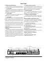


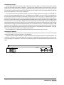
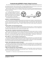

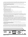


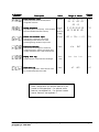

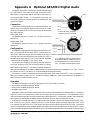


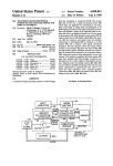


![HiSoft Devpac 3 (text version) [1992] [Manual: PDF]](http://vs1.manualzilla.com/store/data/005668901_1-67cf8256fc448cd2edf58a11a6ec729e-150x150.png)