1
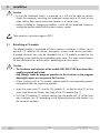
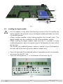
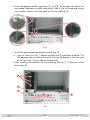
STC 160 Head-End Station QPSK AV module HDC 480 CI AV English Notes on the Assembly Instructions. As well as this supplementary Assembly Instructions, the Assembly Instructions for the STC 160 apply. GSS Grundig SAT Systems GmbH Beuthener Strasse 43 D-90471 Nuremberg Phone: Fax: Email: Internet: +49 (0) 911 / 703 8877 +49 (0) 911 / 703 9210 [email protected] www.gss.de Contents 1 Safety regulations ............................................................................................... 3 2 General information ............................................................................................ 3 2.1 Scope of delivery................................................................................. 3 2.2 Meaning of the symbols used ................................................................ 3 2.3 Technical data ..................................................................................... 4 2.4 Description ......................................................................................... 5 3 Installation .......................................................................................................... 6 3.1 Retrofitting a CA module....................................................................... 6 3.2 Installing the digital module................................................................... 7 3.3 Connecting the digital module ............................................................... 9 4 The control panel at a glance ............................................................................... 9 4.1 Menu items ......................................................................................... 9 4.2 Functions of the control panel buttons ....................................................10 5 Programming .................................................................................................... 10 5.1 Preparation ........................................................................................10 5.2 Programming procedure ......................................................................11 5.3 Programming the digital module ...........................................................12 Selecting the module / channel strip .....................................................13 5.3.1 Programming channel strip “A” .............................................................13 Setting the LNB oscillator frequency ......................................................13 Configuring the CA module, displaying card information .........................14 Setting the input symbol rate ................................................................14 Setting the input frequency ...................................................................14 Setting the station filter ........................................................................15 Selecting the audio stream for a TV channel ..........................................16 Setting the volume level .....................................................................17 Setting the identification of the stereo / dual tone ...................................17 Adjusting the picture format signal, teletext mode ...................................17 Activating test lines .............................................................................18 Setting the subtitle functions .................................................................18 Activating teletext subtitle pages and setting the standard ........................19 Activating DVB subtitle pages ...............................................................19 Activating the black bar ..................................................................... 20 Storing data ...................................................................................... 20 6 Final procedures ................................................................................................ 21 -2- HDC 480 CI AV 1 Safety regulations Please read the safety regulations listed in the assembly instructions for the STC 160 head-end station which pertain to this module. Take precautions to prevent static discharge when working on the device! Electronic devices should never be disposed of in the household rubbish. In accordance with directive 2002/96/EC of the European Parliament and the European Council from January 27, 2003 which addresses old electronic and electrical devices, such devices must be disposed of at a designated collection facility. At the end of its service life, please take your device to one of these public collection facilities for proper disposal. 2 General information 2.1 Scope of delivery 1 1 1 1 2.2 HDC 480 CI AV module AV cable CD (assembly instructions) Brief Assembly Instructions Meaning of the symbols used Important note —> General note – – t / / Optional use of the buttons 1FSGPSNJOHXPSLT -3- HDC 480 CI AV 2.3 Technical data The requirements of the following are met: 2006/95/EC, 2004/108/EC The product fulfils the guidelines and standards for CE labelling. HF input: Frequency range: ......................................................... 950 … 2150 MHz Level: ......................................................................60 dBμV … 80 dBμV Input impedance: ...................................................................... typ. 75 Return loss: .............................................................................. typ. 8 dB Input data rate:................................................................1 … 45 MSymb Output specifications: Audio Noise voltage ratio rated (DIN 45633):..................................... typ. 60 dB Non-linear distortion factor: ......................................................typ. 0.6 % Frequency range: ........................................................... 20 Hz … 15 kHz Level at -12 dB: ..................................................................typ. 500 mVrms Impedance: .............................................................................. typ. 1 k Video Signal-to-noise ratio: ..................................................... typ. 54 dB (rated) Level (75 : ............................................................................typ. 1 Vpp Impedance: .............................................................................. typ. 75 Connections: SAT inputs: ............................................................................ 4 F-sockets Connection strip (20-pin): ................... For supply voltages and control circuits AV output: .......................................................................... 26-pin socket -4- HDC 480 CI AV 2.4 Description The module HDC 480 CI AV, in the following called digital module, has a QPSK AV converter which simultaneously converts four QPSK modulated channels into AV signals. It is equipped with four common interfaces, which enable the decoding of four encrypted channels when used in conjunction with four CA modules and four appropriate smart cards. One channel can be decrypted with every common interface. The digital module has four SAT inputs and one AV interface, through which the decoded AV signals are fed to the corresponding modulator module. Components (e.g. LNB) which are connected upstream can be powered through the SAT inputs. The channel strips “A” “B”, “C” and “D” can be individually programmed. This means it is possible to select up to 4 channels from four transponders. Signal transfer principle: TUNER "A" TUNER "B" TUNER "C" TUNER "D" CA module Channel strip "A" CA module Channel strip "B" CA module Channel strip "C" CA module Channel strip "D" The prepared input signals are fed to the modulator module via the AV interface. From there, they are fed to the HF output collector of the head-end station, through which the level of the output signal can be adjusted via the software in the head-end station. The digital module operating software can be updated using a PC or notebook and the software “BE-Flash” via the 9-pin D-SUB socket on the head-end station. You can find the current operating software for the digital module, the software “BE-Flash” and the current assembly instructions on the website “www.gss.de”. This digital module is designed exclusively for use in the STC 160 head-end station. -5- HDC 480 CI AV 3 Installation Caution – Ensure the head-end station is mounted so it will not be able to vibrate. Avoid, for example, mounting the head-end station onto a lift shaft or any other wall or floor construction that vibrates in a similar way. – Before installing or changing a module, switch off the head-end station or unplug the power cable from the mains power socket. Take measures to protect against ESD! 3.1 Retrofitting a CA module The digital module is equipped with four common interfaces. It allows you to connect CA modules for various encryption systems and service providers. Encoded channels can only be decoded with a CA module suitable for the encoding system and the corresponding smart card. The smart card contains all the information for authorisation, decoding and subscription. Caution – The hardware and software of the module HDC 480 CI AV have been thoroughly prepared and tested. – Any changes made by program providers to the structures in the program data might impair or even prevent this function. – When working with a CA module, please read the corresponding operating manual from the respective provider. t *OTFSUUIFTNBSUDBSE 1 into the CA module 2 so that the chip 3 on the smart card faces the thicker side (top) of the CA module (fig. 1). t 1VTIUIF$"NPEVMF2 without canting into the guide rails 4 of the common interface slot 5 according to the following picture and contact it to the common interface. -6- HDC 480 CI AV 5 4 3 2 1 Fig.1 3.2 Installing the digital module – If a CA module is used, check that the plug contacts of the CA module are tightly seated in the terminal strip on the digital module and make sure there is a reliable contact. – Always position modules which belong together next to each other. The digital module must be installed to the left of the modulator module. – When installing the digital module, make sure that it is inserted in a long numbered groove in front of a contact strip on the board at the rear wall of the housing. The shorter not numbered grooves without a contact strip on the board at the rear wall of the housing are for add-on modules only. t Open the housing of the head-end station in accordance with the assembly instructions for the STC 160. t 0QFOUIFMPDLJOHEFWJDF1 in the direction of the arrow (fig. 2). 1 Fig.2 -7- HDC 480 CI AV t *OTFSUUIFEJHJUBMNPEVMFJOHSPPWFT A and B of an open slot left to the associated modulator module and gently slide it into the head-end station until it makes contact with the board on the rear wall (fig. 3). A C B Fig.3 t *OTUBMMUIFBQQSPQSJBUFNPEVMBUPSNPEVMFGJH —> Figure 4 shows the slots 1 (digital module) and 2 (modulator module). The slot between them (without a contact strip on the board at the rear wall of the housing) is for an add-on module only. t "GUFSJOTUBMMJOHUIFNPEVMFTDMPTFUIFMPDLJOHEFWJDF 1 in direction of the arrow (fig. 4). D G E F 1 Fig.4 -8- HDC 480 CI AV 3.3 Connecting the digital module t $POOFDU4"5*'JOQVUT C of the digital module (fig. 4) to the preinstalled F terminals in the rear wall of the head-end station via the cable inlets E using HF cables made on-site (length approximately 80 cm) or if applicable to one of the outputs of a retrofitted SAT-IF input distributor. t 6TJOHUIFSJCCPODBCMFD to connect the AV output of the digital module to the AV input of the modulator module. 4 The control panel at a glance 4.1 Menu items Program the module using the buttons on the head-end station control unit. The menus appear on the two-line display of the control unit. The parameters and functions to be set are underlined. With the button select the channel strip / other modules. You can use the – – – – – – – – – – – button to select the following menu items: LNB oscillator frequency Symbol rate Input frequency Station filter Audio stream selection Audio output level Stereo decoding / audio type selection Picture format signal (WSS) Test lines Teletext subtitle / DVB subtitle / black shield Store -9- HDC 480 CI AV 4.2 Functions of the control panel buttons M S – – – – To To To To move the cursor adjust values and functions store the programmed data switch to the next menu 5 Programming 5.1 Preparation t $POOFDUUIFEJHJUBMNPEVMFUPBQSPHSBNNFENPEVMBUPSNPEVMF —> For the programming of the output channels please read the assembly instructions of the corresponding modulator module. t $POOFDUUIFUFTUSFDFJWFSUPUIF)'PVUQVUPOUIFNPEVMBUPSNPEVMF t "EKVTUUIFUFTUSFDFJWFSUPUIFPVUQVUDIBOOFMPGUIFDIBOOFMTUSJQUPCFTFU Digital module – channel strip “A” —> modulator module – channel strip “A”, Digital module – channel strip “B” —> modulator module – channel strip “B”, Digital module – channel strip “C” —> modulator module – channel strip “C”, Digital module – channel strip “D” —> modulator module – channel strip “D”. - 10 - HDC 480 CI AV 5.2 Programming procedure Ein/On SETUP BE160 V7 Bx 1A Bx 1A TWIN-SAT Böx 4 TWIN-SAT Bx 1B QUAD C5-12,S3-24 C07 C5-12,S3-24 C07 WDR Köln V1 QUAD Das Erste V1 A M Bx 1A / / Bx 1A LNB 10600 MHz MENU Information *) > M 1/6 / / M *) Die angezeigte Information ist abhängig vom verwendeten CA-Modul The information displayed is dependent on the CA module used Bx 1A SYMBOL / / FREQ / / 27500 M Bx 1A 11836 MHz +0.2 M Bx 1A 01/07 + TV Das Erste / Programmauswahl / Channel selection M AUDIO Bx 1A / 01 / 02 “deu” Das Menü wird nur bei Auswahlmöglichkeit mehrerer Begleittöne angezeigt. This menu is only displayed if several audio streams are selectable. M Bx 1A AUDIO Level 0 dB / -26 … 6 dB M Bx 1A AUDIO mpeg DUAL norm / / M Bx 1A VIDEO WSS off TXT on norm / swap mpeg / VPS / / on / off / on / off M Bx 1A TESTLINES off M - 11 - HDC 480 CI AV WSS off TXT on / on / off / on / off M Bx 1A TESTLINES off M Bx 1A SUBTITLE txt M SUBTITLE Bx 1A off / off / txt / dvb / black 150 M west / east Bx 1A MEMORY S => STORE M 40/10 black / / / / M nur wenn Untertitel verfügbar sind: Sprache auswählen only if subtitles are available: select language 0…63 CANCEL A S 5.3 SUBTITLE Bx 1A –– dvb / / M SUBTITLE Bx 1A west Programming the digital module Notes: – Entries are saved by pressing the button. —> You will be returned to “Selecting the module/channel strip”. – The programming process can be cancelled by pressing and holding the button. —> You will be returned to “Selecting the module/channel strip”. t 4XJUDIPOUIFIFBEFOETUBUJPO Ein/On SETUP BE160 V7 —> The display shows “SETUP BE160” and the software version of the headBx 1A TWIN-SAT end station (e.g. V 7). Böx 4 TWIN-SAT Bx 1B QUAD Bx 1A QUAD C5-12,S3-24 C07 —> The output level of the output collector can be adjusted in the “SETUP” C5-12,S3-24 C07 WDR Köln V1 Das Erste V1 menu (see STC 160 assembly instructions). A M Bx 1A LNB 10600 MHz / / M - 12 - > Bx 1A MENU 1/6 Information *) / / M HDC 480 CI AV *) Die angezeigte Information ist abhängig vom ve The information displayed is dependent on the C Ein/On Selecting the module / channel strip t 1SFTT SETUP repeatedly if necessary to select the particular module (Bx ...) BE160 or channel strip “A”, “B”,V “C” or “D” to be programmed. 7 Bx 1A Bx 1A TWIN-SAT Böx 4 TWIN-SAT Bx 1B QUAD C5-12,S3-24 C07 C5-12,S3-24 C07 WDR Köln V1 QUAD Das Erste V1 M —> The display shows, e.g., the “Bx 1A QUAD” menu. “Bx” indicates the slot LNB “1” Bx 1A indicates slot no. 1 Bx 1A MENU 1/6 Information *) 10600 MHz > ”A” indicates channel strip ”A” ”Das Erste” name of the selected channel / M M “V 1” / software version of the module A / / *) Die angezeigte Information ist abhängig vom verwendeten CA-Modu The information displayed is dependent on the CA module used Ein/On / BE160 / V 7 shows the programming of chan—> The following programming procedure Bx 1A 5.3.1 Programming channelSYMBOL stripSETUP “A” 27500 nel strip "A". M Bx 1A TWIN-SAT / QUAD Böx 4 TWIN-SAT t 1SFTTUIFBx 1Abutton: FREQ Bx 1B QUAD Bx 1A C5-12,S3-24 C07 11836 MHz / C5-12,S3-24 C07 —> The “Setting the LNB+0.2 oscillator frequency” – “LNB” menu is activated. WDR Köln V1 Das Erste V1 M A Setting the LNB oscillator frequencyM Bx 1A / 01/07 + TV Bx 1A Das Erste Bx 1A LNB MENU Programmauswahl / Channel selection *) Information 10600 MHz > M / M Bx 1A 1/6 / / M t 6TJOHUIF buttons, select Mthe digit of the oscillator frequency to be / Das Menü wird nur bei Auswahlmöglichkeit *) Die angezeigte Information ist abhängig vom ve set. AUDIO Bx 1A mehrerer Begleittöne angezeigt. The information is dependent on the t 6TF UIF 01 / 02 “deu” buttons to set the/ oscillator frequency of displayed the LNB being This menu is only displayed if several audio streams are selectable. used. / / SYMBOL 27500 t 1SFTTUIF button. Bx 1A AUDIO M —> The “Configuring the CA module” – “MENU” is activated. Level / 0 dB M Bx 1A AUDIO mpeg DUAL norm M FREQ 11836 MHz Bx 1A Bx 1A +0.2 M/ / VIDEO M/ / / norm / swap mpeg / VPS 01/07 + TV Das Erste - 13 - Bx 1A -26 … 6 dB / Programmauswahl / Channel HDC 480 CIselection AV SETUP BE160 V7 Configuring the CA module, displaying card information Bx 1A menu BxA1A TWIN-SAT 4 TWIN-SAT which is displayed on your TV hasQUAD been providedBxBöx for 1B these settings, QUAD C5-12,S3-24 C07 C5-12,S3-24 C07 screen. WDR Köln to which V 1 CA module is used. For this reaDas Erste The menu V 1 varies according son, please refer to the operating manual of your particular CA module. The A M information is shown on the display of the head-end relevant station. Bx 1A Bx 1A LNB 10600 MHz MENU 1/6 Information *) Ein/On > / / / M display is dependent on the CA module —> *)MThe information shown in the / used. SETUP Information BE160 *) Die angezeigte ist abhängig vom verwendeten CA-Modul displayed on the CA module used t 6TF to selectThe a information menu item on theisVdependent screen. 7 t "DUJWBUFUIFNFOVJUFNXJUI . Bx 1A SYMBOL / t 4FMFDUUIFSFRVJSFEGVODUJPOXJUIUIF buttons. 27500 Bx 1A TWIN-SAT / store the settings. t 1SFTTUIF button to Böx 4 TWIN-SAT Bx 1A M Bx 1B QUAD C5-12,S3-24 C07 C5-12,S3-24 C07 WDR Köln V1 QUAD Das Erste V1 t 1SFTTUIF button. The “Setting FREQ the input / symbol Mrate” – “SYMBOL” menu is activated. Bx—> 1A 11836 MHz +0.2 / M Setting the input symbol Bx 1A Bx 1A LNB 10600 MHz rate MENU 1/6 Information *) > A / / / transponder M 01/07 +rate TV of the /satellite symbol can be found in theM current trans/ Das Erste ponder tables of theProgrammauswahl various satellite/ trade magazines or on the website the vom ve Channel selection *) Die angezeigte Information ist of abhängig The information displayed is dependent on the respective service provider. BxThe 1A M AUDIO Bx 1A / 01 / 02 “deu” Bx 1A SYMBOL / Das Menü wird nur bei Auswahlmöglichkeit mehrerer Begleittöne angezeigt. 27500 / This menu is only displayed if several audio streamsMare selectable. M the t Using buttons, select the digit of the symbol rate displayed to be Bx 1A FREQ set. / Bx 1A AUDIO 11836 MHz t 6TFUIF buttons to set the desired+0.2 symbol rate. / Level 0 dB / -26 … 6 dB M t 1SFTTUIF button. M —> The “Setting the inputBx frequency” menu is activated. 1A 01/07–+“FREQ” TV Bx 1A AUDIO mpeg DUAL norm / / Setting the input frequency M / Das Erste norm / swap mpeg /M VPS Programmauswahl / Channel selection Das Menü wird nur bei Auswahlmögl —> Once the HF receiverBx has AUDIO to the input signal, any offset to 1A synchronised mehrerer Begleittöne angezeigt. Bx 1A the target VIDEOfrequency / is01displayed This menu is only displayed if severa / 02 “deu” in MHz, e.g./ “* 0.2”. WSS off TXT on M Bx 1A TESTLINES / streams are selectable. on / off M Bx 1A Level - 14 - AUDIO 0 dB HDC 480 CI AV -26 … 6 dB *) Die angezeigte Information ist abhängig vom ve The information displayed is dependent on the 1A SYMBOL —> If a question mark “?”Bxappears in the second /line of the display, there is 27500 no input signal present. Check the configuration / of the antenna system and head-end station as well as the preceding settings of the module in M question. Bx 1A FREQ 11836 MHz +0.2 / / t Using the buttons, select Mthe digit of the frequency displayed to be set. Bx 1A 01/07 + TV t 6TFUIF buttons to set the input frequency. / Das Erste Ein/On Programmauswahl / Channel selection t Press the buttons to adjust the input frequency displayed so that the frequency offset amounts to less Mthan 1 MHz. SETUP BE160 —> A status LED indicates the quality of the received input signal: V7 AUDIO Bx 1A 01 / 02 “deu” / LED indicator Signal quality Green Good M Bx 1A QUAD Poor Orange Das Erste V no 1 signal Red Bx 1A AUDIO Level M0 dB / M t 1SFTTUIF button. Bx 1A LNB —> The “Setting the station filter” 10600 MHzmenu is activated. > Bx 1A / mpeg Setting the station filter / AUDIO DUAL norm M M / / Das Menü wird nur bei Auswahlmögl mehrerer Begleittöne angezeigt. This menu is only displayed if severa streams are selectable. Bx 1A TWIN-SAT Böx 4 TWIN-SAT Bx 1B QUAD C5-12,S3-24 C07 C5-12,S3-24 C07 WDR Köln V1 A -26 … 6 dB Bx 1A MENU 1/6 Information *) / / M norm / swap mpeg / VPS *) Die angezeigte Information ist abhängig vom ve The information displayed is dependent on the In this menu, select the channel from the data stream that is to be made availBx 1A VIDEO // Bx 1A SYMBOL able through this channel strip. WSS off TXT on on / off 27500 no transponder” //appears, no input signal If the error message “SERVICE is present. In this case, you shouldMcheck the previous settings as well as the M configuration of the SAT antenna system. Bx 1A TESTLINES If the “scanning ...” message appears on the display, the table of received Bx 1A FREQ / off channels is being read. Please wait until this process is finished. on / off / 11836 MHz +0.2 / As soon as the station filter has found all of the TV or radio channels, the correM M of the head-end station. sponding data appears in the display Bx 1A 01/07 + TV Das Erste Bx 1A SUBTITLE off M / Programmauswahl /SUBTITLE Channel selection Bx 1A txt 150 west B d / Das Menü M wird nur/bei Auswahlmögl AUDIO off / txt / dvb / black mehrerer Begleittöne / angezeigt. This menu is only displayed 01 / 02 “deu” / west / east if severa streams are selectable. Bx 1A M - 15 M HDC 480 CI AV Meaning of the indicators shown in this example: “01/07” – The second of a total of 7 channels has been activated. “+“ – The audio stream for the current TV channel is available in several languages. ”TV” – The data on the Ein/On display corresponds to a TV channel. “Das Erste” – Channel name SETUP BE160 V7 Other possible indicators: “RA” – The data on the display corresponds to a radio channel. “*” – A star indicates that this TV or radio channel is encoded. Bx 1A TWIN-SAT Böx a 4 TWIN-SAT To enable Bx the1Achannels,QUAD a CA module Bx and card from 1B smart QUAD C5-12,S3-24 C07 C5-12,S3-24 C07 the respective service provider are required. WDR Köln V1 Das Erste V1 M —> For radio channels, the background of the screen of the connected TV or test receiver is darkened. Bx 1A MENU 1/6 Bx 1A LNB —> If a service number (e.g. “SERVICE 131”) appears instead of “TV” or / Information *) 10600 MHz > “RA”, this indicates that an unnamed station or an undefined data stream / / is being received. M M / A *) Die angezeigte Information ist abhängig vom ve displayed is dependent on the t 4FMFDUUIFEFTJSFE57PSSBEJPchannel with the The information buttons. Bx 1A SYMBOL / t 1SFTTUIF button. 27500 / or more audio streams, —> If the selected channel is broadcasted with two the “Selecting the audio stream for a TV channel” – “AUDIO” menu will M appear. Otherwise the “SettingBxthe Level” menu is acti1A volume level” FREQ – “AUDIO / vated (see page 17). 11836 MHz +0.2 / M Selecting the audio stream Bx for1Aa TV01/07 channel + TV / This menu only appears ifDas theErste selected channelProgrammauswahl is broadcasted/ Channel with two or selection more audio streams (languages). In this menu, select the desired audio stream M from the transport stream. AUDIO Bx 1A / 01 / 02 “deu” t 6TFUIF Bx 1A AUDIO t 1SFTTUIF button. Level dB —> The “Setting the volume level” –0 “AUDIO Das Menü wird nur bei Auswahlmögl mehrerer Begleittöne angezeigt. This menu is only displayed if severa streams are selectable. M audio stream you want. buttons to select the -26 … dB / menu Level” is 6activated. M - 16 Bx 1A AUDIO / HDC 480 CI AV Bx 1A 27500 Setting the volume level In in Bx 1A t M M M / levels / / AUDIO Das Menü wird nur bei Auswahlmögl mehrerer Begleittöne angezeigt. This1A menu isTWIN-SAT only displayed if severa Bx Böx 4 streams areTWIN-SAT selectable. 1B QUAD ofBxTV and radio stations C5-12,S3-24 C07 C5-12,S3-24 C07 WDR Köln V1 A Level 0 dB -26 … 6 dB / Bx 1A MENU 1/6 Bx 1A LNB / Bx 1A 01/07 + TV / M 4FUUIFWPMVNFMFWFMUPUIFTBNFMFWFMBTUIFMFWFMTPGUIFPUIFSPVUQVUDIBOInformation *) 10600 MHz > / Das Erste Programmauswahl / Channel selection nels using the AUDIO 01 / 02 “deu” Bx 1A this menu, you can balance unequal QUAD volume Bx 1A FREQ M Das Erste V1 the various channel strips. 11836 MHz +0.2 Bx 1A / / M SYMBOL V7 buttons (+6 dB … -26 dB), if necessary. Bx/ 1A M M AUDIO Bx 1A 27500 M WSS off VIDEO / mpeg DUAL norm M / normInformation / swap ist abhängig vom ve Die/ angezeigte *) t 1SFTTUIF button. mpeg / VPS The information displayed is dependent on the Das Menü wird nur bei Auswahlmögl AUDIO Bx 1A —> The “Setting the identification M of the stereo / dual tone” – “AUDIO” mehrerer Begleittönemenu angezeigt. This menu is only displayed if severa 01 / 02 “deu” is activated. / Bx 1A SYMBOL Setting the identification TXT on M / dual tone ofBx the1Astereo M AUDIO / // / streams are selectable. on / off Level 0the dBFREQ In this menu, you can selectBx whether stereo audio -26 … 6 dB is decoded // identification 1A Bx TESTLINES from the VPS data or from11836 the1AMPEG data stream. Further you can swap the MHz +0.2 / M off dual tone. languages on TV stations with on / off / M M Bx 1A mpeg Bx 1A AUDIO DUAL norm 01/07 + TV Das Erste / // norm / swap mpeg / VPS Programmauswahl / Channel selection M data stream from which the identification t 6TJOHUIF buttons, select the (“mpeg” or “VPS”) to beBx used. 1A SUBTITLE Bx 1A B MSUBTITLE Bx 1A VIDEO / ”DUAL t Use the buttons tooffselect the dual tone code …”150 setting. west txt d Das Menü wird nur bei Auswahlmögl WSS TXT on on / off swap” audio / AUDIO 1Aoff between t 6TFUIFCVUUPOT to Bx switch “Dual norm” or “Dual mehrerer Begleittöne angezeigt. / / M M is only displayed This menu if severa / 02 “deu” / streams for dual tone TV01channels. M off / txt / dvb / black streams are selectable. / west / east M Bx 1A TESTLINES t 1SFTTUIF button. off —> The “Adjusting the picture format” – “VIDEO WSS” menu on / offis activated. Bx 1A AUDIO / Level M0 dB / -26 … 6 dB Adjusting the picture format signal,Mteletext mode Bx 1A MEMORY M If problems with the automatic picture format 4:3, 16:9, LetterBx 1A AUDIO switchover / Bx(e.g. S => STORE CANCEL Bx 1A SUBTITLE SUBTITLE 1A box) arise with the connected devices, you can switch “off” the Wide Screen mpeg DUAL norm norm / swap / off 150 west txt mpeg / VPS S Signalling (WSS) in this menu. M In addition you can activate or deactivate the / teletext mode. M / M / off / txt / dvb / black VIDEO / Bx 1A WSS off TXT on / on / off west / east M Bx 1A - 17 - TESTLINES HDC 480 CI AV B d Bx 1A / / Bx 1A LNB 10600 MHz MENU Information *) > M Bx 1A 27500 M Bx 1A Level AUDIO 0 dB mpeg DUAL norm / norm / swap VIDEO / / on / off mpeg / VPS t 1SFTTUIF button. M FREQ / —> The “Activating test lines” – “TESTLINES” menu is activated. 11836 MHz +0.2 / Bx 1A M Bx 1A Bx 1A -26 …“off” 6 dB or “on”. t To activate/deactivate WSS, use the buttons/ to select *) Die angezeigte Information ist abhängig vom verwendeten CA-Modul The information displayed is dependent on the CA module t 5P BDUJWBUFEFBDUJWBUF UFMFUFYU NPEF use theused buttons to select the M teletext mode “TXT on” and use the buttons to switch the teletext “off” SYMBOL / or “on”. Bx 1A AUDIO / / M / / 1/6 WSS off Activating 01/07 + TV test /lines TXT on M Das Erste Channel selection For specific Programmauswahl applications /test lines can be inserted in the teletext in this menu. M Bx 1A 01 / 02 “deu” tM 6TJOHUIF Bx 1A Level / mpeg Bx 1A off SUBTITLE SUBTITLE Bx 1A off 150 txt B west d If youAUDIO you do not button. / want to change this setting, press the DUAL The norm “Storing / norm / swap —> data” – “MEMORY” menu is activated (see page 20)./ / M M mpeg / VPS / off / txt / dvb / black west / east / Setting the subtitle functions TXT on VIDEO / WSS off Bx 1A on / off AUDIO t 1SFTTUIF button. 0 dB -26 … 6 dB / —> The “Setting the subtitle functions” – “SUBTITLE” menu is activated. M Bx 1A / M test lines "on" and "off" buttons switch the M Bx 1A TESTLINES Das Menü wird nur bei Auswahlmöglichkeit off mehrerer Begleittöne angezeigt. This menu is only displayed if several audio streams are selectable. AUDIO Bx 1A on / off This M menu allows subtitles (transmitted in teletext or DVB data stream) to be displayed directly in the channel or parts of the screen to be masked by a black TESTLINES bar. Using the buttons, the submenus can be selected. With setting on / off / Bx 1A is switched MEMORY off. "SUBTITLE - off" subtitle function M M S => STORE CANCEL S Bx 1A SUBTITLE txt M SUBTITLE Bx 1A off / off / txt / dvb / black 150 M dvb / / MEMORY S => STORE S M –– M west / east Bx 1A SUBTITLE Bx 1A west SUBTITLE Bx 1A 40/10 black / / M nur wenn Untertitel verfügbar sind: Sprache auswählen only if subtitles are available: select language / / 0…63 CANCEL A - 18 - HDC 480 CI AV / V O m / on / off M teletext subtitle pages and setting the standard Activating / Das Menü wird nur bei subtitles Auswahlmöglichkeit allows transmitted in teletext to be displayed directly in the BxThis 1A menu TESTLINES mehrerer Begleittöne angezeigt. This menu is only displayed if several audio offchannel. on / off / streams are selectable. To display the characters for Western ("west") or Eastern ("east") European M languages, the corresponding character set can be selected. / t Using the buttons select the submenu "SUBTITLE - txt". -26 … 6 dB Bx 1A SUBTITLE / / / n Bx 1A MEMORY S => STORE S SUBTITLE Bx 1A dvb –– B b CANCEL A This menu allows subtitles transmitted in a DVB data stream to be displayed directly in the channel. The language of the subtitles can be selected. t Using the Bx 1A txt txt / dvb / black M west on / off S M Activating DVB subtitle pages / E 150 txt / Then M the / M digit of/ the page number M t 6sing buttons select the to be set. off / txt / dvb / black / / use/ swap to set each of the three digits. norm west / east nur wenn Untertitel mpeg / VPS t 6sing the buttons select the teletext standard setting, e.g. “west” and verfügbar sind: Sprache auswählen use to select the teletext standard “west” or “east”. only if subtitles are t 1SFTT the button to activate these settings and to leave the “Setting available:the select language subtitle functions” menu. on / off —> The “Storing data” – “MEMORY” menu is activated (see page 20). / SUBTITLE Bx 1A off O Y VIDEO WSS off / Channel TXT onselection/ Programmauswahl O O Bx 1A buttons select the submenu "SUBTITLE - dvb". SUBTITLE 150 west SUBTITLE Bx 1A dvb –– Bx 1A black SUBTITLE 40/10 / buttons select “–M –” and /select the languageMyou want/ using M the t 6sing / / / the buttons. west / east 0…63 nur wenn Untertitel —> This selection is only possible if subtitles are available. verfügbar sind: t 1SFTT the button to activate theseSprache settingsauswählen and to leave the “Setting the only if subtitles are subtitle functions” menu. available: select is language —> The “Storing data” – “MEMORY” menu activated (see page 20). CANCEL A - 19 - HDC 480 CI AV WSS off / on / off M Activating the black bar TESTLINES This menu allows to mask Bx a 1A part of the screen by a black bar. The vertical off on / off position and the height can be adjusted. / t Using the E Bx 1A st dvb / / TXT on t / east M buttons select the submenu "SUBTITLE - black". SUBTITLE –– Bx 1A SUBTITLE black Bx 1A 40/10 SUBTITLE Bx 1A SUBTITLE M setting/ of “vertical txt westof the t the / buttons off select the position 150 / height / / bar” andnur setwenn theUntertitel value you want using the buttons. / / 0…63 M M t 1SFTT theverfügbar button settings and to leave the “Setting sind:to activate these off / txt / dvb / black / the Sprache auswählen M 6sing subtitle functions” menu. only if subtitles are —> The “Storing available:data” – “MEMORY” menu is activated. west / east select language Storing data A Bx 1A MEMORY S => STORE M CANCEL S t "MMQSPHSBNNFEEBUBJTTBWFECZQSFTTJOHUIF button. Then you will be returned to the menu item “Selecting the module / channel strip” (page 13). t 4FMFDUUIFOFYUDIBOOFMTUSJQ“B”, “C” or “D” by pressing the buttons and programme it analogue to the programming of channel strip "A". —> By pressing the button, you will be returned to the menu item “Selecting the module / channel strip” without saving the programmed data. - 20 - HDC 480 CI AV B d 6 Final procedures After installing the head-end station, upgrading accessories or installing modules it is necessary to tighten all cable connections, F terminals and cover screws in order to maintain compliance with current EMC regulations. t 4FDVSFMZUJHIUFOUIFDBCMFDPOOFDUJPOT'connectors) using an open-ended spanner (spanner gap 11 mm). t 5FTUUIFPVUQVUMFWFMPGUIFPVUQVUDPMMFDUPSBDDPSEJOHUPUIFSTC 160 assembly instructions and set the output level required for the cable system. t .PVOUUIFCBTFQMBUFBOEUIFGSPOUDPWFSTFFSTC 160 assembly instructions). Service: Phone: Fax: Email: +49 (0) 911 / 703 2221 +49 (0) 911 / 703 2326 [email protected] Alterations reserved. Technical data E. & O.E. © by GSS GmbH 12112009