1
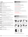
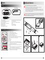
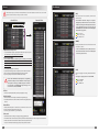
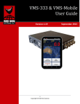
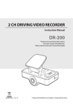
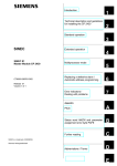
4CHANNEL DRIVING VIDEO RECORDER
Instruction Manual
DR-400
Thank you for purchasing this product.
For proper usages and application,
Please read this instruction manual thoroughly.
ver. 1.0
PRINTED IN KOREA
* Design and Specifications are subject to change without notice.
CONTENTS
SAFEGUARD INSTRUCTIONS ......................................................................................................................... 3
SAFEGUARD INSTRUCTIONS
Please read the “Safety Rules” carefully before using this product. Following the safety rules prevents users from damages related with the misuse of the product. It is very important to follow these safety rules.
We state “Caution” and “Warning” to clarify any potential risk for a damage associated with the misuse of
the product.
PRODUCT FEATURE ........................................................................................................................................... 5
COMPONENTS ...................................................................................................................................................... 5
PARTS ....................................................................................................................................................................... 6
- DVR body .......................................................................................................................................................... 6
- Remote controller .......................................................................................................................................... 6
INSTALL IN YOUR CAR ...................................................................................................................................... 7
PRODUCT OPERATION ..................................................................................................................................... 8
- Power ON/OFF ................................................................................................................................................. 8
- Abnormal Condition Check ........................................................................................................................ 8
RECORDED VIDEO CHECK ............................................................................................................................... 9
- Real time check ............................................................................................................................................... 9
- Check in your PC .......................................................................................................................................... 14
PC VIEWER MANAGER .................................................................................................................................... 15
- PC VIEWER Installation .............................................................................................................................. 15
- PC VIEWER MANAGER Execution ........................................................................................................... 16
- Interface Introduction ............................................................................................................................... 17
- File List ............................................................................................................................................................. 18
- File Attribute .................................................................................................................................................. 19
- Video Control ................................................................................................................................................ 20
- Mode Change ............................................................................................................................................... 21
- Screen Capture ............................................................................................................................................. 21
- Video Exporting ........................................................................................................................................... 22
- 3G Sensor / TIME / TACHOGRAPH .......................................................................................................... 23
- Route Check ................................................................................................................................................... 24
- GPS Information Check .............................................................................................................................. 24
- Configuration ................................................................................................................................................ 25
- System Information ..................................................................................................................................... 29
CHECK POINT BEFORE SERVICE REQUEST ........................................................................................... 30
2
NOTICE
This information is for user’s reference for better usability.
CAUTION
This information is for preventing damage or shorten the life time of the products.
WARNING
This information is for preventing bodily harm or even death and use should follow this safety rules.
WARNING
Please do not install the product where has lots of vibration or not fixed securely. - It may cause traffic accident and injury due to an interruption from detaching the product by vibration during driving.
Please avoid wiring of connected codes from high fever.
- It may cause electric shock and fire from melting of covering for codes.
Do not place near of air bag effective range.
- It may cause malfunction of air bag or accident, injury due to hitting monitor by air bag.
Please confirm the caution according to a kind of vehicle if the vehicle has an air bag.
- It may cause malfunction of air bag if it installed and wired at the wrong place.
Keep clean dust on power socket.
- It may cause electronic shock and fire by bad connection.
Do not put a pin or needle on the hole or crack in the body.
- In case of inserting them, stop to operate, it may cause electronic shock, fire and malfunction.
Do not use in problem condition as like smoking, smell something burn.
- It may cause fire. Stop to use and make inquiries to agency.
Should install while power off. (After install products, connect DC jack)
- It may cause to electronic shock or malfunction.
Do not operate the product while driving.
- It may cause an accident. Stop in a safe place and operate.
Do not put the product in place where sudden temperature increasing and should use on optimum voltage,
temperature and humidity. - It may cause to electronic shock or malfunction.
Do not pull cord with a jerk, should catch a plug and pull. Do not use damaged cord.
- It may cause cord malfunction, electronic shock and fire.
Do not clean exterior with alcohol, volatility or oily solvent. Neither keep touching rubber and plastic for
long time. - It may cause change of surface, fall of paint, malfunction and fire.
3
CAUTION
1 PRODUCT FEATURE
Do not shock to the product.
- It may cause damage or malfunction for product.
- Application of exclusive DVR chip, Stable Operation
Do not place near magnet.
- It may cause malfunction and trouble.
- Application of exclusive PC VIEWER MANGER (Max. support of 12 languages)
Keep the internal GPS without any obstacle near of it like high pass, navigation.
- It may cause problem on GPS signal receipt rate.
- Selection of Memory Type (2.5” HDD or CF card type)
GPS function needs loading time when it power on.
- It needs from few seconds to minutes depending on signal receipt environment.
The vehicle which has metallic tinting on front window could be caused poor GPS reception.
Please careful do not interfere with electric wiring when product is installed in the upper part of dashboard.
- It may cause ignition from a bundle of electric wiring and it makes product damaged.
Please use only the specified components.
- If it is used with non-specified components, it’ll be caused an accident or breakdown of the product because
it damaged the components inside of product or is not fixed properly.
After wiring for the codes, please move it to the location where is not interrupted of driving and coil the
codes with friction tape and fix it by clamp.
- It may cause electric shock or fire as the codes are contacted with the part of car frame.
- It may cause traffic accident if the steering or selector or brake pedal is twined.
Please wire the codes without the contact with moving parts such as seat rail, screw parts and car frame.
- It may cause electric shock and fire by disconnection of short circuit.
- Application of M-JPEG Compression Method
- Consecutive Recording Time : Approximative 8 days Recording with 320GB HDD
- Emergency Recording (Compulsion Recoding about 1 minute by using remote control)
- Parking Surveillance Mode (Ordinary Power Cable - Optional)
- Data Download direct connection with PC and USB
- Assignment of frame(0~15fps, 0~30fpc) within total 60fps at each camera (fps : Frame rate per second)
- The management of driving recording, door sensor, motion sensor through connection of exterior sensor
- Trace of trajectory interlocked with map
- Water-mark for protecting counterfeit of the capture screen
2 COMPONENTS
* If the body and parts mentioned below are not included when you purchase this product, contact the shop
where you purchased the product.
After installation and wiring, please make sure that Brake, Light, Horn, Etc. are operated properly.
- It may cause electric shock and fire, if the product used as above functions are not operated properly.
In case of suddenly changing of brightness such as tunnel enter/exit or extremely dark place, the recording
quality may be low.
When you drive dark place, recommend you to turn on the headlight (fog light) to record with high quality.
DVR body
(including the Key)
HDD case
(2.5” HDD or CF card)
Bracket set
Cable
(Water proof type)
USB download
cable
Video output cable
(optional)
GPS antenna
(optional)
PC VIEWER
install CD
Instruction Manual
Remote controller
(including battery)
Remote Controller
Receiver
Ordinary power
cable
(optional)
Ext. sensor cable
(optional)
When install ordinary power cable, should contact to a specialty store. (The place of fuse box is varying
depending on each car manufacturer. Please check the car manual before installation)
To safe usage on battery, please disassemble ordinary power cable when you do not drive for a long time
(over 3 days). We recommend disassemble to safe driving even though this cable contains a function for
preventing battery dead.
Do not disassemble, repair and remodeling. - It may cause malfunction and injury, can not get warranty.
Make inquiries to agent for repair and checkup.
Please install the product at a level with HDD.
- If the product installed as standing, HDD cannot be read and be recorded.
* The shape of each component may be changed without notice for the better quality.
4
5
3 PARTS
4 INSTALL IN YOUR CAR
DVR body
Please check the following points prior to installation:
Front of DVR body
- Turn off the product before installation, and install the product with the car key taken out.
- Do not use any other unverified cable except for the supplied cable.
- The vehicle which has dark sunting or metallic sunting can be influenced on low GPS receiver rate.
- Make sure of eliminating wave interference around an external GPS antenna and fully separate from
other units such as hi-pass, navigation, etc.
Back of DVR body
A HDD or CF card is available when buying this product, at user’s option. There is no data damage from direct
separation with product because the memory card keeps in private card case. Also, it is convenient to connect
with PC directly using the USB port at the back of case.
Back of Hard case
1
Insert and installation of memory to the HDD case
2
1. Camera Operation LED
2. Recording LED (Parking mode/ Event mode)
3. Remote Controller Sensor
4. Hard Case (2.5” HDD or CF card - Optional)
5. HDD LOCK (Power ON)
6. External Input Terminal
(GPS antenna/ Remote controller)
7. Cable Terminal Socket (Camera/ Video Out/ Power)
8. Sensor Input Terminal
(AVL/ Door Open Sensing/ Move Sensing, etc.)
9. SATA
10. USB download port
11. Motion Cognition LED
HDD or CF card
(Optional)
Remote controller
1. Emergency recording
- Normal recording for about 1 minute
2. Turns ON/OFF the parking monitoring mode.
3. Saves the set value of the menu.
4. Moves the menu and adjust the level value.
5. Menu (Camera setting /Time setting /System information display)
6. Video search (Event list search /Time list search)
7. Reverse
8. Play /pause
9. Forward
10. Converts video of the camera and turns ON/OFF the recording.
- If clicked shortly, it converts into camera video; if clicked long, it
turns ON/OFF recording of the camera.
11. Displays split screen mode and turns ON/OFF recording of all cameras.
- If clicked shortly, it displays split screen mode; if clicked long, all the
four cameras turn ON/OFF the recording simultaneously.
12. Displays screen information (Recording time, Proper channel, GPSrelated information when connecting GPS)
6
3
4
5
7
5 PRODUCT OPERATION
Please be fully familiar with the followings before operating the product.
- Operation of the remote controller is possible only when an external monitor is connected. (VIDEO OUT)
- All settings except for simple operations of the camera settings are available in the setting window of PC VIEWER.
(Please refer to page 25)
6 RECORDED VIDEO CHECK
Real time check
- If connected to a separate monitor, the recorded video can be viewed real time. At initial use, check the basic setting
by connecting to an external monitor prior to use to make sure of proper product use.
1. Basic Video Check
Power ON/OFF
1. This product has no separate power button. After installation and wiring, it’ll be stand-by condition once insert a hard disk. (Turn on the REC/
EVENT LED and CAM 1 ~ 4)
If HDD is un-locked, the recording does not execute. If HDD locked during leaving it as it is stand-by, there could
be happened the error on the product. So, please start recording as soon as insert a HDD into the Hard Case.
2. When receiving the GPS signal, the GPS / PARK LED is flickering at a
intervals of 1second for 30seconds. and if it is converted into parking
surveillance mode, the LED lights. When receiving GPS signal at parking surveillance mode, the LED is flickering at a interval of 1second for
30seconds and then the LED lights along with parking surveillance
mode. If the parking surveillance mode is converted with normal mode,
the LED lights at a interval of 1second.
3. REC / EVENT LED is blinking at intervals of 1second from start to the
end of Event.
Whole Screen
4-Channel Split Screen
4. Upon an emergency, click the Emergency Recording button on the remote controller, and recording begins. Recording is made for about 1
minute from the start of recording, it the REC / EVENT LED turns off until
the end, and CAM1~4 LED will be off at an interval of 1 second.
5. When it converts into parking monitoring mode while the power cable
(optional) is connected, Park LED is on and recording begins in parking
mode.
- Shortly press the Number key on the remote controller, and then it converts into the whole screen of the channel, and it may convert
into a split screen with the Split Screen button.
- Regardless of the setting on PC viewer, the motion sensing is “on” automatically when it is switched to the parking mode. So, if it detected some movements, REC/EVENT LED can be turned off with lighting of PARK LED at
intervals of 1second same as occurrence of EVENT.
- If the power cable(optional) is directly connected to the car battery, power will not turn off even if the car is
turned off. If the product should be fully turned off, separate the hard case mounted on the product.
Abnormal Condition Check
1. If the camera has an error at recording, LED of the camera becomes off.
In this case, the camera video will not be recorded, so be sure to check
any abnormal condition. ex ) CAMERA2
2. If an HDD is not recognized while the product is normally connected
and power is on, PAK and EVT LED become fast off.
3. If there are no images at the all channels or all recordings of cameras
were turned off, REC / EVENT LED were turned off and CAM1 ~ 4 LED
are fast off.
8
- The icon indicates that it is being recorded. As pushing the Number key or division button more than 2 seconds to make recording
ON/OFF, and if recording becomes OFF, the icon disappears, and then the recording release icon appears.
9
2. Check and Change of Camera Setting
3. Time Reset
- Click the [M] button on the remote controller to enter the menu window. Select the camera icon shown at the bottom of the monitor
to enter the setting change window.
- Use the Operate button to change the basic settings such as brightness/color of each camera image.
* The set value applies to the recorded video from the changed time.
- Click the [M] button on the remote controller to enter the menu window. Select the time setting icon shown at the bottom of the
monitor to enter the setting change window.
- Reset time with the Operate button.
* The set value applies to the recorded video from the changed time, and top priority is given to GPS time when mounting GPS.
10
11
4. Recorded Video Search
5. Video Control
- Click the Search button on the remote controller to search only
the event list or all the lists by order of time.
(UP : Time Search / DOWN : Event Search)
- It can check recorded video which was searched by the event or time lists by using video control button.
<Event List Search>
- Search the event list, and then you can view the event occurrence time and attribute. (GPS / Motion sensing / External sensing / Overspeed, etc.)
- Select the desired video with the Operate button.
- The event lists was marked as “DATA NO. - DATE - TIME - EVENT
ATTRIBUTE - CHANNEL”
(e.g.) ”YY/MM/DD Hour : MINUTE : SECOND MOT 1CH”
MOT : Motion Sensing
G-SENSOR : Shock Sensing
SENSOR : Exterior Sensing
SPEED : Over speed Sensing
EMERGENCY : Emergency Recording
<Time List Search>
- Click the [Yes] button, and then an arrow appears, enabling the user to select the desired time zone. After it is selected, click the
Search button at the bottom to search the video.
- It played the latest video if there is no recorded video at the time slot for searching or if it searches the video before/after the recorded
time.
12
Video Control Icon
/
: Play/Pause (Toggle)
: Reverse (4 steps – gradually fast reverse)
: Forward (4 steps – gradually fast forward)
- If you want the function to get out to the recording condition,
please press the menu button in search screen.
13
7
6. Video Information ON/OFF
PC VIEWER MANAGER
Specifications of PC VIEWER MANAGER
CPU : Pentium 4 2.0 GHz at least
OS : WINDOW 98 /ME / 2000/ XP/ VISTA/ WINDOW 7
VIDEO : Geforce Grade 4 at least
- Basically, information about the recorded video appears as shown below, however, click the [DISP] button on the remote controller,
and then you can turn off all the information. Click once again, and then the information appears again.
- If the HDD capacity is full, it’ll be showed up ‘
‘. The elder data is deleted sequentially and saves as overwriting form.
Memory : 1GB RAM at least
HDD: 1GB at least
User Authority : Administrator
PC VIEWER Installation
PC VIEWER MANAGER needs separate installation. Put the enclosed CD in your PC, double-click the setup.exe file, and go on the following installation.
HDD Recording Capacity
Recording Date and Time
Recording Channel
GPS Info. and Registration Marks
(when connecting the GPS antenna)
: Recording
: Cancellation Recording
Check whether or not the shortcut
icon is installed on your desktop.
: Motion Perception
: Sensor Perception
Check in your PC
1. Install the dedicated VIEWER in your PC. (please refer to page 15)
2. Separate the hard case from the product and directly connect to your PC using the USB port on the back.
3. If it is exceuted the installed VIEWER, the product recognize exterior HDD automatically and read a video to the file
list of VIEWER.
4. Click the Play button of VIEWER to see the recorded video.
- According to the user’s pc condition, the supported USB’s power supply is different with each computer. So,
please connect USB at the two ports so that it can be read the external HDD.
- Search the recorded HDD in Windows Explorer, and then the message ‘Empty disk’ appears, and it is actually
recorded, although no data can be found. This is for data security, so be sure to use the dedicated PC VIEWER to
view the recorded video.
14
- If a graphic card that is not supported in your PC is mounted
or a graphic card of low specification is used, the message
shown in the right is displayed in a message window when
installing this program. This means that DirectDraw is not
supported by your PC so GDI will be used.
- Click the OK button, and the program is run again the PC
viewer program.
15
PC VIEWER MANAGER Execution
Interface Introduction
Double-click the icon shown in the left on the desktop, and then the following screen appears and PC VIEWER MANAGER is executed.
If your PC and a hard disk are normally connected to execute the viewer program, the message ‘A new drive device is detected’
appears as shown below. Click the OK button, and the viewer program opens, and the recording video saved in the disk automatically appears in the file list.
If there is no initially recorded video or several HDDs are connected to your PC, or connection between
your PC and disk is not well done, the file list may not be imported. Then, click the [Import Disk] button,
and the hard disk can be directly selected.
Import Disk
Please select the HDD as DVR-MOBILE
form and then press OK button so that it
can be open the file lists.
If the HDD has recorded video or can record the video, it should be showed the DVR-MOBILE form when
it pressed OPEN DISK button. If it is selected the HDD as other form, it cannot read the file lists. So, please
confirm the HDD that it is DVR-MOBILE form.
File Play
Select the file from the file list and double-click, or click the
Play button at the bottom, and then the video plays.
When you set the password on setting menu this screen
is appeared. Input a password, then program is executed.
(Please refer to Page 26)
If the password is not correct, above message is appeared.
16
1. Play screen
Displays recorded video.
2. 3G/TIME/TACHO
Displays 3G sensor / recording date and time search / Tachometer (car driving speed information).
3. Volume control
Adjusts sound. (mute/volume +,-)
4. Movie control
Reverse (~x2048) / previous frame / play(pause)/next frame/forward(~x2048)
5. Play speed control
Adjusts play speed (x1/4 ~ x4)
6. Minimize
Minimizes the program. (with the Taskbar)
7. 1:1 screen
Displays the recording video suitably to 1:1 size.
8. Full screen
Displays just the recording video in form of a full screen. (It gets out to normal screen once push the ESC key.)
9. Maximization
Maximizes the program. (Maximizes the program suitably to the monitor screen size.)
10. Exit
Ends the program.
11. File list / Extend file list
Displays a displayable file in the hard disk. (an extension list to be displayed by right-clicking)
12. File search
Searches the file list by date and time.
13. Map info.
Displays the route at the driving time on the map. (displayable with a popup window by right-clicking)
14. GPS info.
Displays GPS information at the driving time.
15. Screen capture
Saves the screen being currently played in a picture file. (*.bmp)
16. Export to movie
Selects start point and end point of the video to be exported to your PC and saves in AVI.
17. Split mode Selection
Selects the screen split mode.
18. Auto reverse
Repeatedly plays the video.
19. Configuration
Displays the configuration window where detailed setting of the product is available.
20. Program info.
Displays version and information of the program.
17
File List
File Attribute
When the cursoris placed on file list and extended file list, it doesn’t match between the movie on the screen and file
list. Please use mouse wheel to move up and down on the list.
[ALL]
Shows the time list of all recorded files, and knows the
event files easily.
General File List
Extension File List
* The information about the setting of over speed is
displayed by red letters instead of color box and it is
classified according to the limited speed that users set
on the configuration of Viewer. So, please press the
LIMIT SPEED button at the TACHO so that it is displayed.
(Please refer to page 23 ; 27)
Green - 3G event
Yellow – Sensor event
Blue – Motion event
[EVENT]
It displays the attribute of the event in front of the time list
as classify in a color box.
1. Import the file saved in your PC.
* Only available if importing the separately saved JVP file to be exported to your PC.
(For an AVI file, it cannot be read by the viewer program.)
* It does not marked twice same as [ALL] because it is
based on the time and it can move to the starting time
of event once presses the list.
2. Open an external HDD.
* Once a hard disk including recorded video is just connected to your PC at initial
use, a file list automatically appears, however, it is used if there are several HDDs
connected to your PC or if connection to a hard disk is well done but an initial file
list does not appear.
1. Click the [Import Disk] button in the file list.
2. Select the disk including the video to be imported, and then click the Yes button.
3. If it is not indicated, click the [View All Forms] button and select the disk.
4. Upon an opening error, “Execute under administrator’s authority.”
Execute under administrator’s authority due to strengthening
of Windows security in versions of Windows 7 or Vista or higher,
certainly. (when connecting to a HDD) Please press the OK button after shows up the Administrator rights message on the
screen when it is connected with HDD.
[LOG]
Shows power supply and recording ON/OFF time information.
* The log list is only supported on an external HDD.
Green - POWER ON
Yellow – REC ON
Blue – POWER OFF
3. File sort
1. A file list can be divided into all files, event files, and log files for sorting.
4. View file attribute
1. All the saved files are in form of [second-minute-hour-day-month-year].
2. The attribute information is divided for indication with file sorting. (Please refer to
Page19)
5. Extend file list
1.Click the [Extend List] button to extend the list, and then more resources can be
viewed at a time with a separate window on the right.
2. Click once again, and it returns to a general list screen.
6. Time search
1. It is differently viewed according to OS language setting. (e.g.) PM 12:03:02
2. The initial time value is the value at the top of the list, and when the file list is clicked, search time is changed into the clicked time.
3. Find the date and time and click the Search button, and then it searches for the time.
* In case of an overwritten hard disk, it may pause at the last point of the hard disk.
18
19
Video Control
Mode Change
- Whenever clicking the Mode button, it changes into each split mode.
- Touch and double-click the mouse on the video, and then it converts
into the channel of the video. Double-click once again, and then it converts into the previous split screen mode.
1. Play / Pause
Plays / pauses the file selected from the file list. (Toggle button)
2. Previous Frame / Next Frame
Stops the screen several seconds after(before) the video being played.
3. Reverse / Forward
Reverses or forwards while increasing speed of the video being played by two folds (x2). (up to x 2048)
4. Speed Setting
Sets the speed of the video being played (x 1/4 ~ x 4)
5. Play Status
Indicates the direction, status, and speed of the video being played.
6. Play Location
Indicates the current play location in the video being played.
Double Click
Each
Channel
Split
Screen
Double Click
The split status is set 4CH from the factory regardless camera connection. The maximum available channels to
be displayed in the viewer can be selected in the Recording setting of Configuration. When setting in 2CH, just a
two-split screen can be displayed with the Mode button, so please perform setting according to the connecting
status of the camera. (please refer to page 27)
ex)
Screen Capture
- If the Screen Capture button is clicked, the screen being
played is saved in an image file, and the saving folder is
called automatically
- Extension and saving route :
Same route as BMP / video exporting (C\DVR\AVI)
The saving route of the file may be manually changed in the Configuration tab. (please refer to page 27)
- All images which save as letting out were applied by water-mark for protecting from counterfeit.
- Even it can be figured out the counterfeit of image with the unaided eye due to the elaborate modification, it can figure out
the original or fake by using special program for protecting.
- If it opens by viewer program which can revise the file such as Paint, Photoshop and saves the file with itself or saves it with
other name, there is a possibility to be recognized as modification data and this will not be adopted as proof for accident.
20
21
Video Exporting
3G Sensor / TIME / TACHOGRAPH
- If the Video Export button is clicked during play, the start point of the video to be exported appears on the progress bar. Click
the button once again, and the video play stops, and the export window appears.
3G Sensor : If shock is sensed on the X/Y/Z axis during video recording, a graph per time is created as shown in the fol-
Start Point
lowing picture. The up-and-down severely shaking point(indicated in a dotted line) on the graph shows the
event(accident) onset time, and the greater the shock is, the more the differential of the graph is.
End Point
- If the end point is ahead of the start point, it will not be saved normally.
- Extension and saving route: Same route as JVP, AVI / screen capture (C\DVR\AVI)
- The 3G sensor graph shows vibration of the car based on the x/y/z axis.
(X axis : front/rear shock / Y axis: left/right shock / Z axis : up/down shock)
- Sensitivity of the 3G Sensor is adjustable into 0~20 steps in Configuration. (please refer to page 27)
TIME : You can easily view and select date, time, and minute of the saved video by clicking the TIME button on the left.
Recorded Date (Red)
Recorded Hour/Minute (Green)
TACHOGRAPH : It can figure out the driving recording of vehicle by clicking the TACHO button on the left.
1. Extension
Selects saving of either JVP(Video Law) file or AVI file.
2. Channel / Sound
Selects and saves the channel and sound.
3. PC Capacity
Displays the available and remaining capacities of your PC.
4. Preview
Previews and saves at the same time in AVI Saving.
5. Check the file size
Check the size of saved files. (JVP : 2GB division save, AVI : less tan 200MB save)
6. Codec Setting
Recommends the use of Xvid Mpeg-4 Codec.
7. Progress Display
Displays the conversion progress.
- If Xvid Codec is not installed in your PC, It can be downloaded by pushing the Xvid button at the VIEWER’s System info.
tab. Also, for user who can’t use internet, we provide xvid.exe file with you on VIEWER.
- The JVP file is an exclusive file for PC Viewer, so it is not played in a universal player, for example, Windows Media
Player, like AVI file.
- It can save 2GB division only for JVP recording and avilable for whole movie backup without capacity limit. For AVI
file, it can save a file less than 200MB. Please check it again if the file is more than 200MB, the loading speed might
be slow and stop.
- The AVI file is saved in “[Car Number.] Start time–End time_GPS_PW-Ext.Channel name”
- The JVP file is saved in ”[Car Number.] Start time–End time_Part number_All number”
22
The speed of the cursor place
Overspeed limit designated
in Configuration (green)
Speed graph by time zone (red)
The starting time of Recording
The last time of Recording
Maximum Speed during Driving
* It only applies when the JVP file plays, and it plays from the point by moving with a mouse in the graph and then clicking it.
23
Route Check
Configuration
When the setting window opens by clicking the Configuration button, you may change and save the setting.
- It is marked SETUP_DVR.ini once push the set-up configuration button if the PC is not connected with HDD. This
means initial default value.
- Users can save files randomly more than an file by using SAVE button and can load a file among loaded files by using LOAD
button.
The driving route can be viewed on the map with the GPS.
1. You can zoom in/out the map with the +/- button.
2. When the button is clicked, you can pick out the popup
window to view the screen in a larger one.
3. The map moves by clicking the Pause button on the expansion map and dragging and moving the map. Also, the map
can be zoomed in or out with a Mouse Wheel.
SAVE : Save setting value as the other name
GPS Information Check
LOAD : Load setting value
- It is marked a file name which saved lastly on the top of set-up screen if the PC is not connected with HDD.
Ex) When it saves or loads as bbb.ini file
You can see speed, time, direction, and location information at the driving time with the GPS.
Date and time at driving
- It is marked “PYSICALDRIVE” regardless of saving or loading and it is only changed a set-up value as the situation if PC is connected with HDD.
Speed at driving (graphic)
Direction at driving
Location at driving
If Save is clicked after changing the value in the setting window while your PC and a HDD are connected, it asks
again if or not to overwrite the changed value on the connected disk.
Speed at driving (numbers)
- If “Yes(Y)” is clicked, all the changed values are saved in the connected disk, and the message window showing success in
change is viewed.
- If “No(N)” is clicked, the changed value is canceled, and it returns to the original state when the window opens initially.
24
25
1. Basic System and User Information Setting
2. Recording Setting
1. Language Select
The initial settings are in English, and total 12 languages are available.
2. Speed Indicator Unit
Selects the speed indicator unit of GPS information. (km/h, mile/h, knot)
3. Date / Time
Selects the current date and time. (Sync : it is automatically adjusted to the current time of your PC.)
2. Speed Limit Setting
Sets the reference speed limit to estimate overspeed record.
4. UTC
Selects the Universal Time Coordinated (UTC).
3. Recording Quality
Sets the recording quality. (high resolution / moderate / low resolution)
5. RTC Apply
Applies the setting adjusted time to the product.
4. Recording Frame Setting
Sets the recording frame for the camera. (30 per channel; total 60fps should not be exceeded.)
6. Summer Time Apply
Applies summer time.
5. Shock Sensitivity
Sets sensitivity of the 3G sensor into 1~20 steps. (Perform road test prior to setting.)
7. User PW Setting
Sets password in the PC-viewer program. (up to 8 digits, special characters/numbers/letters available)
6. Format
Deletes all data in a HDD for initialization. (Any deleted data is irrecoverable.)
8. PW Apply
Enables to run the program only after entering PW
7. File Location
Sets saving location of an image capture file or video to be sent.
9. User Car Number Setting
Set the user car number, and it is viewed in the screen at recording.
8. Initialize
Initializes the whole setting. (factory defaults)
10. Initialize
Initializes the whole setting. (factory defaults)
9. Set Value Importing
Imports the saved set value of the user.
11. User Set Value Importing
Imports the saved set value of the user.
10. Setting Saving
Saves the changed set value.
12. Setting Saving
Saves the changed set value. (Saves in the user set value in a HDD is connected and in a PC if it is not connected.)
13. Go back to previous (UNDO)
Returns to the condition before change without saving the set value.
- Time information saved by checking “Apply to RTC” is applied from the point of time when operation starts by putting a HDD
in the product, so it may be somewhat different from actual time. (It only recommends to use the “APPLY TO RTC” Function
when the product is initialized or has a noticeable difference between recorded time and operation time.)
- It is recommended that time should be reset with the remote controller on the monitor irrespective of RTC application
whenever using the monitor (optional).
- Even at time setting, if a GPS signal is received, GPS time is reset with top priority.
26
1. Channel Select
Selects the max. channels to be displayed in the viewer.
(e.g., Only 2 split screens are viewed when selecting 2CH.)
(Saves in the user set value if a HDD is connected and in a PC if it is not connected.)
11. Go back to previous (UNDO)
Returns to the condition before change without saving the set value.
- On frame setting menu, it can control between 0fps~30fps and totally max. 60 fps for 4CH.
- If it is set as ‘0’ or exceed totally ‘60’, it displays in red as below picture and it displays error message without saving
the value. (It is same as parking mode for fps setting).
27
3. Camera and External Sensor Setting / Parking Monitoring Mode Setting
System Information
You can see the current version information by clicking the SYSTEM INFO button and download various data
such as newest firmware, Xvid Codec.
Newest Firmware Download
Xvid Codec Download
1. Audio Support
Sets audio support. (voice mute when releasing the check box)
2. Motion Sensing
Sets motion monitoring per channel.
3. Mirror function
It sets reverse image on the screen.
4. External Sensing
Sets external sensor monitoring per sensor. (sensor 1~4)
5. Parking Mode (Auto/ Manual)
Automatically converts into parking mode unless there is a car movement for a fixed time with
the 3G sensor. Manually converts into parking monitoring mode by pressing the remote controller or the external key.
6. Frame Setting
Sets the recording frame for the camera at parking mode. (30 per channel; total 60fps should not be exceeded.)
7. Initialize
Initializes the whole setting. (factory defaults)
8. Set Value Importing
Imports the saved set value of the user.
9. Setting Saving
Saves the changed set value.
(Saves in the user set value in a HDD is connected and in a PC if it is not connected.)
10. Go back to previous (UNDO)
Returns to the condition before change without saving the set value.
- In parking mode, the motion sensors for all channels are on regardless motion detecting setting value. You can check
the icon on the screen if it detects any movement.
28
29
CHECK POINT BEFORE SERVICE REQUEST
* You can solve some problems as below with simple check. If you still have a problem though you try as below
instruction, please contact to service center or store that you purchased.
Q The front recording LED is not working though power is connected.
A
Q Forget the password for recorded file or for PC VIEWER.
A
- Please re-install the pc viewer after un-installing if it is forgotten the PC Viewer’s password.
- If it is forgotten a password for recorded file, please input the “camos”. So then, you can pass the password screen as temporarily. After that, please designate new password for PC VIEWER.
- Please insert HDD or hard case with CF card. The power is supplied when the connectors between SATA of the rear side of
hard case and power should contact tightly.
: In case of the password for recorded file, it can be only set by exporting of JVP file.
- If you still have LED problem when you insert a hard case, check and replace the power cable.
Q The occurrence of event file by oscillation is odd.
Q It is rebooted continuously.
A
Q After boot up, the clock of the play screen does not changed nor work any function.
A
A
- It will be happen when HDD or CF card has not connected. Please check the disk.
Q It keeps going to change to the motion recording mode without setting of it.
- It will be happen when HDD has not locked. Please lock the HDD with enclosed key.
A
Q The screen is black though the camera is connected.
A
- Please check the setting value of fps setting of the channel on recording setting menu is ‘0’. (It is normal if the fps setting
value is ‘0’, it does not record that cannel and LED is off )
Q The OSD data such as time, channel no. is not displayed.
A
- Please press DISP button and check OSD data setting on/off.
Q When it is searching for time, it can’t searching for the wanted time.
A
- It will be happen when the camera has not connected. Please check the camera connecting parts.
Q When install PC viewer, it shows security warning window. (Problem of viewer compatibility)
A
- If it is not recorded video at the time zone you are searching, it is searching the nearest time zone from the zone you are
searching.
Q The recorded file is saved with difference of the value of recording setting.
A
Q The 4 camera LEDs blink rapidly.
A
- 3G sensor will be checked at the parking surveillance mode from the factory mode. According to this fact, if there is no oscillation for 5minutes, all channels’ motion detection will be On as it is automatically changed to the parking surveillance.
If you do not want this function, please clear the check of 3G sensor part at the packing surveillance.
- Please press M(Menu) button to check DISPLAY ON in camera setting menu. If it is OFF status, please change it ON.
Q The LED is of though the screen is playing connected camera.
A
- Please change the value of 3G sensor. The less value of 3G sensor is, the more often event will happen. The other way, the
value is increased, the event might not be happened with weak oscillation. Nevertheless the value is lower, if the event is
not happened, please contact the after service center.
- There are 2 modes of setting the recording which are normal recording and parking surveillance recording. At the normal
recording mode, it is recorded with FPS setting value. At the parking surveillance recording mode, it is recorded the with
parking surveillance mode’s FPS setting value. Please check each setting values.
Q The present time was changed on the screen.
A
- It is happen depending on security setting status of the computer when the PC version is over Vista or Windows 7. It is not
an error, click OK then you can use it without problem.
- If the product has not been used for a long time, the setting value can be initialized by discharged battery. With this fact,
the time is set as the last time of recording or it sets as June 15th, 2011. (If it is connected with GPS, the time is automatically synchronized with GPS time.)
Q It shows up warning screen.
Q Can I use HDD or CF card that I used on PC ?
A
- It can be connected. The system of this product is low level recording system without OS and general purpose file system.
It records orderly and strong for data conservation but weak for compatibility due to its own file system. So we recommend to use HDD in factory mode, not NTFS nor FAT32. If you should use a formatted disc in NTFS or FAT32, all the data
recorded in the disc will be deleted, please back up the date before use.
A
- If the HDD and Viewer’s versions are different with each other, it shows up the warning screen. Please upgrade F/W at the
PC viewer’s “SYSTEM INFO.” screen.
Q The power is off during updating. After that, the product is not operating.
A
- Please receive after sales service from the purchasing agency.
Q There is no message for new disc though running the PC viewer after disc connecting.
Q Another Serious Problems
A
A
- Please check the LED placed right side of USB port, it should blink red.
- Please check the disc recognition status on the bottom of window Start – Setting – control panel – computer administrator – disc administration.
- It selects the disk as HDD is read properly but it does not play it at the viewer. Or the video lists at Hard Disk are damaged.
- It can’t be back-up the program due to damaged HDD.
- There is real recorded videos by randomly formatted from DVR’s serious problem.
: If there are some serious problems included with above symptoms, please send the product and hard-disk to the manufacturer without connection with DVR. Because if DVR is connected with HDD, the videos cannot be restored by overlaying.
30
31
INSTRUCTION MANUAL