1
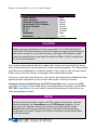
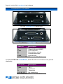
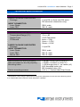
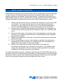
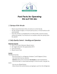
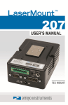
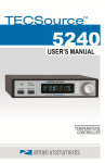
Page 2 · 212/214 DIL LaserMount User’s Manual
Introduction
Thank you for choosing the DIL LaserMount from Arroyo Instruments. The DIL
LaserMount is designed for high performance and long term use.
For applications requiring case temperature control, the 214 TEC DIL
LaserMount integrates an 8W Peltier cooler for precise control of the package
temperature. With an operating range of -5°C to 85°C, the TEC DIL LaserMount
should cover most of your case temperature control needs.
Both DIL LaserMounts are heavily finned to provide the highest heat dissipation
capability, allowing you to operate at more extreme conditions or higher powers.
Both mounts also have an array of screw down mounting options available with
the removable base.
The 212 DIL LaserMount can also be used for mini-DIL devices, although it
does not provide any heat sinking capability.
The DIL LaserMount also offers all the features you would expect from a
modern DIL laser diode fixture, including:
•
•
•
•
Designed to be quickly integrated with Arroyo’s LaserSource and
TECSource instruments.
Industry-standard D-sub connectors and pin-outs allow for quick
integration into existing laser applications.
Screw terminals for all 8 or 14 pins of the device, allowing for easy,
solder-less configuration of the fixture.
The 214 TEC DIL LaserMount features three standard connectors,
eliminating the need for custom cabling to the two TEC interfaces.
212/214 DIL LaserMount User’s Manual · Page 3
Installation and Use
Wiring the mount to your device: Start by configuring the wiring of the mount
to match your DIL or mini-DIL laser. To do this, remove the four screws from the
bottom of the fixture and lift off the base plate. This will give you access to the
screw terminals inside the fixture.
Internal Wiring Example
Using the wiring guide below, connect the wires to the appropriate pins of the
DIL or mini-DIL. The wires are color coded for easy identification.
Page 4 · 212/214 DIL LaserMount User’s Manual
Signal
Color
Laser Anode
Red
Laser Cathode
Black
Photodiode (PD) Anode
Green
Photodiode (PD) Cathode
White
Chassis Ground
Brown
TE (+)
Orange
TE (-)
Yellow
Thermistor
Blue
Thermistor
Violet
Fixture Wiring Guide
CAUTION
Make sure the LaserMount is earth grounded. The 1220 LaserSource
and 1260 TECSource cables ground the fixture to earth ground through
the shell connector. If you are not using 1220 and 1260 cables, make
sure the LaserMount is grounded through the DB9 or DB15 connectors,
or via the banana jack.
Your mount was shipped with four rubber feet, which can be used if the fixture
will not be bolted to an optical bench or other mounting system. The feet prevent
the fixture from skidding on a smooth surface. If you plan to use the feet, install
them now in the four corners of the label side of the bottom plate.
Once you have wired the mount for your device and optionally installed the feet,
place the base plate back on the mount and screw in the four screws.
Connect to Laser Diode Driver and TEC Controller: Next, connect the DIL
LaserMount to your laser diode driver and temperature controller. For the 214
TEC DIL LaserMount, you will need a second temperature controller for the
case temperature control.
NOTE
Arroyo Instruments offers Laser and TEC cables designed to connect
directly between our LaserSource and TECSource products. If you
use your own cables, ensure the connections are properly made
between the instrument and the mount, and that proper grounding
techniques are used. The pin-out of the connectors can be found later
in this document.
212/214 DIL LaserMount User’s Manual · Page 5
WARNING
Be sure you are properly ESD protected before handling your laser. For
additional information, read the section titled “Laser Diode Protection”
later in this manual.
Mounting your device: Remove the two small mounting screws from the DIL
mounting plate, open the ZIF socket, and carefully place your DIL or mini-DIL
laser into the ZIF socket. Make sure the fiber is exiting through the gap provided
in the front of the mount.
For DIL devices, screw in the mounting screws, but do not over tighten, as you
can strip the threads in the mounting plate. For mini-DIL devices, leave the
screws out of the fixture. Close the ZIF socket.
Loading of the Device
Your mount is now ready for use. Additional technical information can be found
below.
Page 6 · 212/214 DIL LaserMount User’s Manual
Connector Pin-Outs
212 DIL LaserMount Connectors
214 TEC DIL LaserMount Connectors
DB-9 Pin
Description
1&2
No connection
3
Chassis Ground (GND)
4&5
Laser cathode
6
Photodiode cathode
7
Photodiode anode
8&9
Laser anode
Laser DB-9 Connector Pin-Out
On the 214 TEC DIL LaserMount, both TEC DB-15 connectors are pinned
identically.
DB-15 Pin
Description
1&2
TE (+)
3&4
TE (-)
7
Thermistor
8
Thermistor
5, 6, 9 – 15
No connection
TEC DB-15 Connector Pin-Out
212/214 DIL LaserMount User’s Manual · Page 7
Technical Specifications
FICATIONS
212 DIL LaserMount
LASER PACKAGE SUPPORTED
Package
INPUT CONNECTOR
Laser Diode
Laser TEC
214 TEC DIL LaserMount
TEMPERATURE CONTROL
Temperature Range (°C)1
Sensor Type
TE Module
LASER PACKAGE SUPPORTED
Package
INPUT CONNECTOR
Laser Diode
Laser TEC
Mount TEC
GENERAL
Size w/ base (H x W x D) [in(mm)]
Size w/o base (H x W x D) [in(mm)]
Mounting holes
Device mounting screws
1
14-pin DIL or 8-pin mini-DIL (miniDIL electrical connection only)
DB-9, male
DB-15, male
-5 to +85
10kΩ Thermistor
Imax = 3.9A
Vmax = 3.75V
Qmax = 8.2W
14-pin DIL
DB-9, male
DB-15, male
DB-15, male
1.55(38) x 4.50(114) x 5.00(127)
1.35(34) x 3.50(97) x 5.00(127)
¼-20 through-hole, 4” on center (x2)
8-32 threaded holes (x4)
M5 threaded holes (x4)
4-40 x ¼” Socket Head Cap Screw
Temperature control range is dependent on the power dissipated into the heat sink. Mounting fixture
to an optical table will increase the heat dissipation capability.
Page 8 · 212/214 DIL LaserMount User’s Manual
Mechanical Specifications
Top View
Bottom View with Base Plate Removed
212/214 DIL LaserMount User’s Manual · Page 9
Laser Diode Protection
Electrostatic discharge and current spikes can be a significant cause of damage
to laser diodes, but when proper precautions are taken, these risks can be
greatly reduced or eliminated. Arroyo Instruments’ controllers offer state-of-art
laser diode protection, but no instrument can fully shield the laser from damage.
Please take these considerations into account when operating your laser:
1.
2.
3.
4.
5.
6.
Always set the current limit at or below the maximum current your laser
can handle. This prevents the device from accidentally driving the
current too high, either via the set point or from the modulation port.
This also provides additional current limiting protection from ESD.
Always work in an ESD safe operating environment, including the use
of wrist straps, ESD grounded work surfaces and floors, and ESD-safe
tools.
Where the AC power to the laser driver to temperature controller may
be noisy, use isolation transformers or uninterruptible power supplies
that provide isolation.
Make sure all cables are securely connected and fastening screws are
screwed in tight.
Do not route power cords or other cables in parallel with the laser or
temperature controller cables, as coupling may occur between the
cables and inject noise into the laser diode.
While it is not possible to create a ground loop through the
LaserSource because of it’s isolation of all inputs, it is possible when
using other equipment. Ensure that any other equipment is properly
isolated to avoid any ground loop problems.
For additional ESD protection, adding 3.5μH (Mouser P/N 542-FB73-287) ferrite
beads as close to the laser diode as possible is recommended. One ferrite bead
should be used on each laser diode and photodiode diode anode and cathode,
with the wire going through the bead at least twice (two turns).
Page 10 · 212/214 DIL LaserMount User’s Manual
Warranty
Arroyo Instruments warrants this product to be free from defects in material and
workmanship under normal use and service for a period of one (1) year from
date of shipment. It does not apply when the product has been misused, altered
or damaged by accident or abnormal conditions of operation. If found to be
defective during the warranty period, the product will either be repaired or
replaced at Arroyo Instruments's option.
THIS WARRANTY IS IN LIEU OF ALL OTHER WARRANTIES, EXPRESSED OR
IMPLIED, INCLUDING IMPLIED WARRANTIES OF MERCHANTABILITY OR
FITNESS FOR ANY PARTICULAR PURPOSE. ARROYO INSTRUMENTS SHALL
NOT BE LIABLE FOR ANY INDIRECT, SPECIAL, OR CONSEQUENTIAL
DAMAGES RESULTING FROM THE PURCHASE OR USE OF ITS PRODUCTS.
Service and Support
For service and support, contact your local distributor or Arroyo Instruments.
Telephone:
Facsimile:
Email:
Web:
Address:
+1 (805) 481-6684
+1 (805) 481-6628
[email protected]
http://www.arroyoinstruments.com
373 Front Street, Suite B
Grover Beach, CA 93433
USA