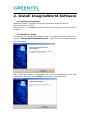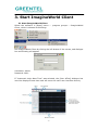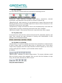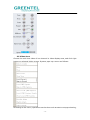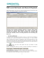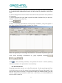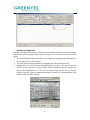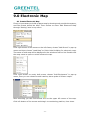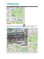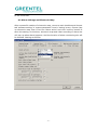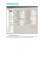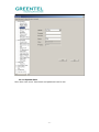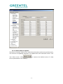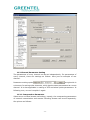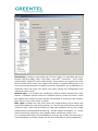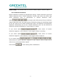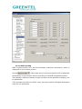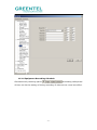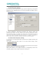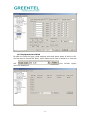
1
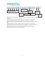
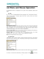
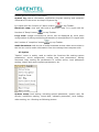
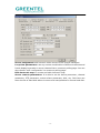
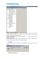
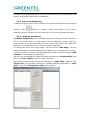
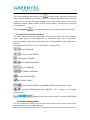
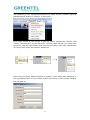
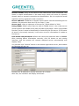
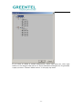
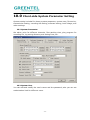
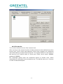
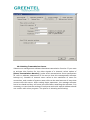
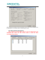
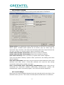
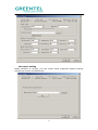
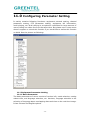
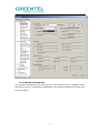
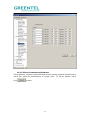
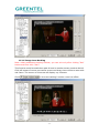
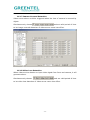
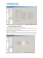
GREENTEL
ImagineWorld Central Management Software
User Manual
For MX100 HSUPA PTZ Network Camera
-1-
ANNOUNCEMENTS ......................................................................................................................... 4 1. IMAGINEWORLD INTRODUCTION .................................................................................. 5 2. INSTALL IMAGINEWORLD SOFTWARE ........................................................................ 7 2.1 OPERATION ENVIROMENT ........................................................................................................... 7 2.2 INSTALLATION GUIDE .................................................................................................................. 7 3. START IMAGINEWORLD CLIENT ..................................................................................... 8 3.1 START IMAGINEWORLD CLIENT ................................................................................................. 8 3.2 TOP TOOLBAR .............................................................................................................................. 9 3.3 TOP MENU BAR ............................................................................................................................ 9 3.4 TOOLBAR ON LEFT SIDE.............................................................................................................. 9 3.5 VIDEO AREA ............................................................................................................................... 10 3.6 BOTTOM TOOLBAR ..................................................................................................................... 11 4.0 MENU AND MOUSE OPERATION .................................................................................. 13 4.1 FILE............................................................................................................................................. 13 4.2 OPERATION................................................................................................................................. 13 4.3 OPTION ....................................................................................................................................... 14 4.4 HELP ........................................................................................................................................... 16 4.5 MOUSE OPERATION ................................................................................................................... 16 5.0 REAL-TIME VIDEO DISPLAY AND CONTROL ........................................................ 18 5.1 REAL-TIME VIDEO FRAME CONTROL ........................................................................................ 18 5.1.1 DISPLAYING MODE SWITCHING ........................................................................................... 18 5.1.2 SINGLE FRAME DISPLAYING ................................................................................................. 18 5.1.3 FULL SCREEN DISPLAYING .................................................................................................... 19 5.1.4 LOOPVIEW MONITORING ...................................................................................................... 19 5.2 PAN/TILT/ZOOM CONTROLLING ............................................................................................... 20 5.3 CAMERA MANAGEMENT ............................................................................................................. 20 6.0 LOCAL RETRIEVAL AND RECORD PLAYBACK ....................................................... 24 6.1 RECORD RETRIEVAL................................................................................................................... 24 6.2 FILE DOWNLOAD........................................................................................................................ 25 6.3 RECORD PLAYBACK .................................................................................................................... 26 7.0 ALARM ACTION ..................................................................................................................... 27 8.0 AUDIO MONITORING AND TALKBACK .................................................................... 28 9.0 ELECTRONIC MAP ................................................................................................................ 29 -2-
9.1 CREATE ELECTRONIC MAP ........................................................................................................ 29 9.2 ALARM LINKAGE AND ELECTRONIC MAP .................................................................................. 31 10.0 CLIENT-SIDE SYSTEM PARAMETER SETTING ................................................... 32 10.1 SYSTEM PARAMETER ............................................................................................................... 32 10.2 SYSTEM USER.......................................................................................................................... 32 10.3 FILE SERVICE .......................................................................................................................... 33 10.4 SETTING TRANSMISSION SERVER ......................................................................................... 34 10.5 VIDEO HARD DISK MANAGEMENT ......................................................................................... 35 10.6 SOFTWARE SETTING ............................................................................................................... 36 10.7 LOCAL LINKAGE ....................................................................................................................... 36 10.8 OTHER SETTING ...................................................................................................................... 37 11.0 CONFIGURING PARAMETER SETTING .................................................................. 38 11.1 EQUIPMENT PARAMETER SETTING ......................................................................................... 38 11.1.1 BASIC PARAMETER .............................................................................................................. 38 11.1.2 NETWORK PARAMETER ........................................................................................................ 39 11.1.3 WIRELESS NETWORK .......................................................................................................... 40 11.1.4 SYSTEM USER ...................................................................................................................... 41 11.1.5 SAVE-REBOOT-UPDATE ...................................................................................................... 42 11.2 CHANNEL PARAMETER SETTING ............................................................................................. 43 11.2.1 COMPRESSION PARAMETER ................................................................................................ 43 11.2.2 MOTION DETECTION ............................................................................................................ 45 11.2.3 OSD OVERLAP .................................................................................................................... 46 11.2.4 EQUIPMENT RECORDING SCHEDULE.................................................................................. 47 11.2.5 VIDEO PARAMETER ADJUSTMENT....................................................................................... 48 11.2.6 IMAGE AREA MASKING ....................................................................................................... 49 11.2.7 CAMERA COVERED DETECTION .......................................................................................... 50 11.2.8 VIDEO LOSS DETECTION .................................................................................................... 50 11.2.9 JPEG CAPTURE PARAMETER .............................................................................................. 51 11.3 PTZ PARAMETER SETTING ..................................................................................................... 52 11.4 ALARM PROBE PARAMETER SETTING ..................................................................................... 52 11.5 EQUIPMENT HARD DISK ......................................................................................................... 53 12. SUPPORT .................................................................................................................................. 54 -3-
Announcements
Thank you for choosing our product. ImagineWorld is central management software
for MX100 HSUPA PTZ Network Camera.
Please read this manual carefully before installing the software.
Copyright Announcement
Copyright GREENTEL LIMITED 2010.
All rights reserved.
Reproduction, transfer, distribution or storage of part or all of the contents in this
document in any form without the prior written permission of GREENTEL is
prohibited.
Information Edition: GL – A – IW – 1.0
-4-
1. ImagineWorld Introduction
Real-time video display: it can display real-time video images of 1-16
channels one page within monitoring network. It can realize single frame,
4-frame, 6-frame, 8-frame, 9-frame, 16-frame partition display. Also it can
support polling display.
Pan/tilt controlling: within authorized range, the orientation, pitching
angle and focus of the camera can be changed by the control of front end
pan/tilt and lens
Remote Video Recording: video file can be stored in build-in hard disk of
front-end video server or storage device with USB interface.
Local video recording: video recording can be achieved automatically by
setting recording time or by alarm signal received from video server.
Real-time video image capture: it is auxiliary function for real-time
monitoring. It will save the single frame from dynamic images in BMP format,
and it can capture images during monitoring or playback.
Image capture of video server: it refers to direct capture by the front-end
video server. And its format for capturing is D1 in JPEG format. The image
quality will not be affected by network transmission.
Audio monitoring and Bidirectional talkback: bi-directional audio
transmission can be achieved between client-side and front-end devices.
Client-side can monitor the audio of front-end device; meanwhile, client-side
can also transmit audio to front-end device and realize real-time bidirectional
talkback.
Alarm action: client-side will start recording, display electronic map and
real-time recording according to settings after receiving alarm signals from
front-end device.
Electronic map display: electronic map contains name of the scene under
monitoring and corresponding front-end devices in it. Click the icons of
front-end video devices distributed in the map, and then the real-time image
of the devices will be displayed.
Local playback: video files of devices at any time in the recording can be
-5-
retrieved and replayed.
Remote playback: to retrieve, replay and download the recording files in
front-end device or other recording files in ImagineWorld Client.
-6-
2. Install ImagineWorld Software
2.1 Operation Enviroment
Operating system: Windows 2000server/professional/XP/2003server
Network protocol: TCP/IP
Client-side PC:P4/128MRAM/40GHD/ video card supporting zoom, DirectX7.0
or above.
2.2 Installation Guide
Open folders of management software and run (double click left button of the
mouse) “ImagineWorldClientSetup.exe”, and then the following dialogue
box will appear:
Next, follow the prompt of installation tool until the appearance of the step
displayed as following. Click [Finish] to complete the installation.
-7-
3. Start ImagineWorld Client
3.1 Start ImagineWorld Client
Select the software in [Start] menu---- program groups-----ImagineWorld
Client, which is showed as following:
Run ImagineWorld Client by clicking the left button of the mouse, and dialogue
box as following will appear:
Username: admin
Password: NULL
If “Automatic Login Next Time” was selected, the [User Affirm] dialogue box
won’t be displayed next time and will enter the main user interface directly.
-8-
3.2 Top Toolbar
You can manually choose different shortcuts as following picture:
【 Alarm 】 : After entering, everyday login, alarm, connection, external
connection, and abnormal exit log can be viewed in system log.
【Data Enquiry】:After entering, you can choose one or many video servers and
defined period to retrieve recorded video files in local or front-end server or the
record file in the server and replay.
【LoopView】: Images connected to server can be displayed by turns after the
configuration of polling monitoring parameters has been configed.
【Electronic Map】: View and edit electronic map which has been created.
3.3 Top Menu Bar
In top menu bar, there are four menu items such as File, Operation, Option, and
Help. They include the main functions of setting and manipulation in this
software. It’s showed as follows:
3.4 Toolbar on Left Side
【Local Out】: It is used to display and control the connection or disconnection
of alarm output relay in external alarm box of computer host. If the alarm
output relay engaged, then the output indicator would be lighted up. Vice versa,
clicking and light this indicator up will activate alarm output.
As follows:
【Alarm Out】: Indicator for alarm output status. The output indicator would
light up if alarm output relay engaged. Also you can click the lindicator to light
it up; this will also activate the alarm output.
Pan/tilt control button:
-9-
3.5 Video Area
Choose the real-time video of one channel in video display area, and click right
button on selected video screen. System pops up a menu as follows:
According to the menu, operations can be done such as start or stop previewing,
- 10 -
connecting or disconnecting camera, local or remote recording, jpg image
capture, temporary alarm defense organization or remove, and camera setting,
etc.
Delect Window: delect the allocation of a certain channel of a certain video
server on video window.
Play or stop the camera: you can choose whether connect the software to
server. If choosing to disconnect with the server, all video and information of
the equipment cannot be displayed.
Start or stop previewing: you can choose whether display the image of video
server connected by this video window. When the preview is stopped, computer
still keep connected with video server, no image is transmitted. It saves
resource.
Local recording: you can choose start or stop local recording.
Remote recording: you can choose start or stop remote recording.
Local BMP capture: this is a real-time video capture function, which is to save
single-frame images from dynamic images in BMP format under appointed
folder of local monitoring host. The path of save can be modified in ‘Option’
menu—‘system setup’.
Remote JPEG capture: this is a real-time video capture function, which saves
single-frame images from dynamic images in JPEG format under appointed
folder of built-in hard disk of video server.
Start local JPEG capture: this is to start the local JPEG format image capture.
Choosing it will activate two options, ‘Local JPEG capture single’ and ‘stop local
JPEG capture single’.
Local JPEG capture single: this is a real-time video capture function, which
saves single-frame images from dynamic images in JPEG format under
appointed folder of local monitoring host. The path of save can be modified in
‘Option’ menu—‘system setup’.
Stop local JPEG capture: this is to stop the local JPEG format image capture.
Disable Alarm: temporarily cancel the alarm defense setting of a certain
channel of a certain video server.
Enable Alarm: it’s a corresponding setting option to temporary defense
remove. It let the alarm defense start.
Camera Parameter: all parameters of the camera can be set here. No right to
set the parameters of the server if you log in as users instead of administrator.
And the dialogue box cannot be opened, either.
3.6 Bottom Toolbar
- 11 -
Multi-frame controlling
Page up and
down
Image
capture
Full
screen
disconnection
Bidirectio
nal Audio
Record
【 Multi-frame controlling 】 : 1-frame, 4-frame, 6-frame, 8-frame, 9-frame,
16-frame
【Full screen】: Video image displayed on the screen will be maximized
【Page up and down】page up and down to monitor more channels
【Disconnection】: Connection between current channel and server can be cut
off
【Image capture】: Instant image of current channel can be captured
【Record】: Choose to record files to local computer or remote video server
【Bidirectional Audio】: Start or stop playing the Bidirectional Audio
【Clear alarm】: Clear the alarm notification
- 12 -
Clear
alarm
4.0 Menu and Mouse Operation
ImagineWorld Client is composed of four parts: Files, Operation, Option and
Help.
4.1 File
By “File” menu of ImagineWorld Client operations like “Lock/Unlock Screen”,
“Save Current Status”, “System Login” and “Exit” can be carried out. Picture
showed as following:
Lock/Unlock screen: system will require to input user’s name and password
after clicking this button. No operations can be done, but relative setting like
alarm recording, etc. will not be locked. Click again and the status will be
unlocked after typing in the user’s name and password.
Save current status: save current status so that the software will continue to
work the same as current status at next starting.
System login: log in the client side of ImagineWorld Client. (for initial
installation the uses’ name is “admin” and the password is NULL)
Exit: exit ImagineWorld Client program.
4.2 Operation
“Operation” menu is mainly used to enquire historical video files, view system
log, edit and use electronic map, and polling monitoring for selected channel.
Showing as following picture:
Query history files: mainly used to control real-time video and recording files
in center. It can also be achieved by clicking “Quary” button
- 13 -
in the top
toolbar and the function is the same.
System log: status information, application program starting and operation
information of the server are kept in system log.
It is equal with the function of ‘alarm’ button
on top Toolbar.
Electronic map: view and edit built-in electronic map. It is equal with the
function of ‘Emap’ button
on top Toolbar.
Loop view: images connected to server can be displayed by turns when
configuration of polling monitoring parameters is accomplished. It is equal with
the function of ‘LoopView’ button
on top Toolbar.
Audio Broadcast: edit the list of audio broadcast so that video server sides in
the list can receive audio information from the manage host computer side.
4.3 Option
“Option” menu is mainly used to realize the functions like setting system
parameters, server assignment, setting loop view parameters, editing
electronic map, setting the parameters of remote server, local parameter
setting, import and export system parameters, etc.
System setup: local setting, including system parameter, system user, file
service, redirection setting, record disk, software parameter, local linkage,
other setting, etc. Showing as following picture:
- 14 -
Server assignment: add network video servers to be central managed.
Loop view parameters: use any custom combination of different cameras and
frame displaying modes in server channel list to construct polling page. You can
also choose ‘auto configuration’ to construct polling page.
Edit electronic map: to create and edit electronic map.
Server remote parameters: It is able to set the device parameter, channel
parameter, PTZ parameter, sensor alarm parameter, disk, etc. Disk item can
show the list of hard disk status in server and manipulation to format hard disk.
- 15 -
Server local parameters: it includes two selecting items, external alarm
parameter and external sensor linkage. Mainly sets the alarm function of
external alarm device of local server.
Export parameter: export system parameter in a certain time into file for
storage and backup.
Import parameter: import system parameter into system; need to reboot
program for going into effect after successful import.
4.4 Help
Version and copyright information of ImagineWorld Client displayed by ‘help’
menu
4.5 Mouse Operation
- 16 -
Click left button of mouse on one video frame to choose the video. Double click
left button of mouse on one video frame, if there is video in the frame, then the
video will be displayed in full screen mode; double click the screen again, it will
return to previous displaying mode.
- 17 -
5.0 Real-Time Video Display and Control
Real-time video controlling function of ImagineWorld Client can realize the
control of displaying images, PTZ and carry out some practical processing on
video images.
5.1 Real-Time Video Frame Control
Real-time Video Frame Control contains multi-frame switching, polling
displaying control, page up/down, devices ordering and main screen display.
5.1.1 Displaying Mode Switching
ImagineWorld Client supports six displaying modes: single-frame, 4-frame,
6-frame, 8-frame, 9-frame, and 16-frame. 16-frame displaying mode is system
default mode. When starting ImagineWorld Client, system will display the video
of anterior 16 channels in device list of this client-side in 16-frame mode. Users
can
switch
displaying
modes
by
toolbar
at
the
bottom.
5.1.2 Single Frame Displaying
Click
mode.
button in bottom Toolbar and switch to single-frame displaying
- 18 -
In single-frame displaying mode, users can set fluency level of playing and code
quality of selected video channel separately.
5.1.3 Full Screen Displaying
To display single or multi-frame video at full screen size and hide all menus and
toolbars. Click
button in bottom Toolbar and switch to full screen
displaying status; double click the frame to exit full screen displaying status.
5.1.4 LoopView Monitoring
LoopView monitoring refers to display the video of all channels in the device
list of client-side page by page under current displaying mode (single or
multi-frame). It can be achieved only when users group which the client-side
belongs to is authorized to carry out “Loopview Monitoring”
If connect with more than one camera, you can choose “Add Page”. You can
choose the partition mode of displaying the pages (e.g.: single-frame, 4-frame,
6-frame, 8-frame, 9-frame, 16-frame displaying mode), and then choose “Add
Channel” in each page to add camera.
Also you can set displaying mode for polling monitoring in ’Display Mode’ and
then click ‘Auto Config’ to realize above function.
Polling time for each page can be set separately in ’Stay Time’. Method: click
“Pages List”, and set time interval for images switching separately in “Stay
Time”, then click ‘Change Stay Time’ after setting.
- 19 -
After accomplishing the setting, click
in top toolbar, and then system will
start polling displaying for real-time video, and display the videos of all channels
in device list of client side page by page according to the number of currently
displayed frames. When system enters polling status, all buttons in interface
can’t be used.
Click ‘Loopview’
in top toolbar again to exit polling displaying status.
5.2 Pan/Tilt/Zoom Controlling
The client-side can control the pan/tilt and lens of the device at front-end only
when users group of this client-side is authorized with “PTZ Controlling”.
Authority limits of this client-side will be set in ImagineWorld Client application
software.
ImagineWorld Client can carry out following control of PTZ:
Lens UP/DOWN
Lens turn LEFT/RIGHT
Auto rotation ON/OFF
Lens ZOOM UP/DOWN
Focus FAR/NEAR
Iris ZOOM UP/DOWN
Invoke PRESET POINT
Set PRESET POINT
Loop PRESET POINT: Loop PRESET POINT setting and invoke
Auxiliary Equipment:switch ON/OFF, max. Support 8 auxiliary
equipments.
Speed of the movement of the P/T camera FAST/SLOW
5.3 Camera Management
The client-side can allocate server only when users group of this client-side is
authorized with ’Server Management.
Before this, if video servers are in the same LAN, please make sure that the IP
- 20 -
net segment of your equipment conforms to video servers. Choose 【Server
Management】 button in “Option” in top menu.
Click right button of the mouse in pop-up server assignment window, and
choose “Add Projects” in pop-up menu. Choose “Add Groups” for newly built
project by clicking right button after entering the name, then click right button
for newly built group and choose ‘add server’.
Enter server’s name, address and port number, users name and password in
pop-up dialogue-box. If one of them is filled incorrectly, an Error type dialogue
box will pop up.
- 21 -
Server’s name: refers to the name of the video server to be connected. This
name is unique identification in the same area, which will serve for dynamic
domain name or transmit connection as identification. So it is required to avoid
repetition during registration and connection.
Server address: IP address or domain name can be used as connecting server
address. Pay attention that don’t fill the ‘http://’ part.
Server port: refers to data port of the server, which default is 3000.
Using DDNS: DDNS refers that the built-in DDNS client in the video server
works together with DDNS client-side provided by developer. When using DDNS
function, server’s name is identification of searching for this server. If the name
of server is incorrectly entered, it will return to error information of unable to
find server.
User name and password: default user name and password both is 888888
After entering above information correctly, click ok button to exit setting
interface, and the system will connect assigned server automatically and
display video.
You can also click “Search” button in the bottom right-hand corner, and window
as following will pop up:
Double click IP address to choose and click ok to finish.
After this, the interface will display as follows:
- 22 -
If you want to delete a certain assignment, which has been set, click right
button on the target video server in server allocation dialogue box to generate
a pop-up menu. Choose ‘delete server’ in the pop-up menu.
- 23 -
6.0 Local Retrieval and Record Playback
Within authorization, the client can retrieve and play back the video files in the
server. The retrieval window is showed as following:
Retrieval and recording playback functions contains: MP4 format
recording file retrieval and playback, ASF format recording file
retrieval and playback, JPEG format recording file retrieval, BMP
format file retrieval, server recording playback, local recording play
back, etc.
6.1 Record Retrieval
To retrieve video recording files stored in server or local server according to
recording time of selected equipment and recording type, it is easy to obtain
video recording files correctly. Equipments under retrieving must be in the
equipment list at client side, otherwise they cannot be retrieved. The client-side
can carry out retrieval only when the users group that this client-side belongs is
authorized with “Video Recording Retrieval”.
Click
under top menu, and system will pop up window of Video
Recording Retrieval.
Choose recording file which you want to enquire according to necessity in
.
Local retrieval: to retrieve video files stored in local host computer
Front-end server retrieval: to retrieve video files stored in the video server.
It is required to select and input the name of video server.
- 24 -
1) Set wanted date and time zone for retrieval, and only the video recording to
be retrieved within selected time zone can be found out; default is entire time
zone.
2) Choose equipment channel under retrieval from the pull-down box; default is
all channels
3) Choose wanted file type (MP4 File/ASP File/JPEG File/BMP File) for retrieval;
default is MP4 format video file.
4) Click
.
If there is recording information meeting those conditions, they will appear in
the video information list under window, as follows:
When the quantity of recording information is more than 20 pieces, you can
view
more
recording
information
by
page
up/down
buttons
.
Click
in this operating interface, the system will return to main operating
interface and save the parameters automatically.
6.2 File Download
Download operation can be run to the file retrieved. In the enquiring result list,
click right button on the file wanted to be downloaded. Choose ‘download’ in the
pop-up menu, and it is done. If retrieved recording file is MP4 format, you can
choose ‘download and transfer to ASF’ item in the menu, it is downloaded and
save as ASF format file
- 25 -
6.3 Record Playback
Choose recording files that you want to played back, double click the recording
information and a preset video player will pop up, by which you can see the
video.
¾ The recording will skip forward to any position by dragging the setting lever
at low part of the video player;
¾ You can adjust playing speed by dragging the speed setting lever;
¾ Displaying sizes (50%/100%/150%/200%/full screen) for video files can
be set in the top menu of the player. Some formats may not support to
switch the displaying size. The size of buffer area can be set, to assure
fluently playing. Also it possesses auxiliary function of changing files from
MP4 format into ASF format.
- 26 -
7.0 Alarm Action
Alarm system will be set by ImagineWorld Client application software. Client will
receive the alarm signals sent by application software and carry out
corresponding actions on the alarm.
Reactions on the alarm includes recording, capturing and triggering alarm
output for triggering channels according to the preset parameters. And you can
choose whether upload these files to central server directly.
- 27 -
8.0 Audio Monitoring and Talkback
Within authorization limitation the client can monitor the audio of front-end
equipment and intercommunicate with it as well. Working mode is full duplex.
The monitoring function at this client side is controlled by equipment voice
switch at bottom Toolbar. Click the switch to connect or disconnect the audio
playing of front-end equipment.
The intercommunicating function at this client side is controlled by equipment
intercommunication switch at bottom Toolbar. Click the switch to connect or
disconnect the intercommunication with front-end equipment.
- 28 -
9.0 Electronic Map
9.1 Create Electronic Map
Firstly it is necessary to build up plane map by drawing tools outside the system,
and the format should be bmp. Then choose to enter ‘Edit Electronic Map’
through ‘Setting’ item in top menu.
Click right button of the mouse on the left frame; choose “Add Scene” in pop-up
menu and then choose “Load Map” to finish initial building for electronic map.
The name of built map will be displayed in the window of server list. Double click
the map name to open or switch electronic map.
Click right button on newly built scene, choose “Add Equipment” in pop-up
menu, then you can choose to add camera, alarm probe or alarm output.
After selecting you can find camera icon on the upper left corner of the map.
Click left button of the mouse and drag it to monitoring position, then close.
- 29 -
in top menu. Images currently
After returning to main interface, choose
under monitoring can be displayed by clicking camera icon on the map.
Functions of ImagineWorld Client electronic map is to download and display
electronic map in application server, and update the electronic map downloaded
- 30 -
to the client side.
9.2 Alarm Linkage and Electronic Map
After successful creation of electronic map, return to main interface and choose
tab ‘software setting’ in ‘system parameter’ item in ‘setting’ menu. Choose ‘pop
up electronic map’ item in list box ‘alarm action’ and click ‘confirm’ button to
save this setting. At this time, electronic map and video recording of alarm site
will pop up when alarm happens. And the location of alarm monitoring site will
be marked. Setting as follows:
- 31 -
10.0
Client-side System Parameter Setting
System setting includes five items: system parameter, system user, file service,
transmission setting, recording HD setting, software setting, local linkage, and
other settings.
10.1 System Parameter
Set alarm voice for different channels, files packing time, play program for
recording file, log saving directory and saving time, etc.
10.2 System User
You can add and modify the user’s name and the password; also you can set
authorization limit for different users.
- 32 -
10.3 File Service
Turn on the access to server from remote host.
After turning on the access function of data retrieval can be realized only when
service port, user’s name and password of the host computer are consistent
with those setting of remote host computer. The system default is: the status of
this service is on. Default value is: server port: 3000, user’s name: 888888,
password: 888888.
File download speed limits the download speed of remote host, which
manipulate file download from accessed server. The default value is 0; it means
no limit of download speed.
- 33 -
10.4 Setting Transmission Server
Video server management software has data transmission function. If you want
to activate this function for the video signals of a channel, select option of
[Start Transmission Service] (under which transmission server parameters
all refer to address parameters of the server that this management software
belongs to). Number of channel users refers to the maximum of users for
connection, and number of system users refers to the total amount of users that
connect with this server. After setting these parameter, the manage software
has to be closed and they will come into effect after restarting the software. It is
necessary to note that the setting of local ports and multi-switch address should
not conflict with other program. The picture is showing as following:
- 34 -
After finishing the setting of the transmission service end, other equipment can
be switched on to connect with the transmission server.
10.5 Video Hard Disk Management
Type, capacity and total spare space of local recording HD can be
displayed here. Users can also choose where to save the video
recording independently.
- 35 -
10.6 Software Setting
This setting mainly works on the working mode and status of software.
Alarm action: the awakening mode when cameras in video server list generate
alarm signal, includes three options as no action, pop up video, pop up
electronic map. Hereinto, the video and according electronic map of alarm site
will pop up when you choose option ‘pop up electronic map’;
Action when double click server: have three modes to choose.
Action when double click camera: have three modes to choose.
Auto alarm cleanup: clean up alarm by system after alarm happens.
Time of auto alarm cleanup: system clean up alarm at the setting time after
alarm happens.
Auto save link status: save the current connection status between client-side
software and video server. Client-side software will read the last saving
connection status when restart next time.
Auto reconnection after abnormally disconnection: when video server
connected by client-side software abnormally disconnected, system will
automatically require connecting again, even without manual operation.
10.7 Local Linkage
Mainly set the communication between host and external serial-port device. Pay
attention when you set. The choice of serial ports should have no confliction.
- 36 -
10.8 Other Setting
When software is running, you can invoke other programs without leaving
monitoring screen simultaneously.
- 37 -
11.0 Configuring Parameter Setting
It mainly contains following functions: equipment network setting, channel
parameter setting, PTZ parameter setting, equipment HD information,
multi-playing, etc. Multi-playing is an optimum resolution for large amount of
users visiting one video server at the same time. But please note: some router
doesn’t support or unlock this function if you would like to realize this function
on WAN. See the picture as following:
11.1 Equipment Parameter Setting
11.1.1 Basic Parameter
The basic parameters of server consist of version info, mode selection, setting
reboot time, and language selection, etc. Hereinto, language selection is the
selection of language about overlapping date and time on the real-time image.
It has Chinese and English options.
- 38 -
11.1.2 Network Parameter
The network parameters of video server or IP camera can be modified. Note
that server have to reboot after modification of network parameters so that they
come to effect.
- 39 -
11.1.3 Wireless Network
This setting is only useful to wireless IP camera, which has wireless function.
User can choose to use CDMA network or 802.11g wireless network.
- 40 -
11.1.4 System User
More than one users’ Username and password can be set.
- 41 -
11.1.5 Save-Reboot-Update
The time of network video server and client-side host can be set synchronously.
The function of updating program is to update files with extension name ‘.itm’
into video server. Click
to restore the default value of video
server parameters from factory.
- 42 -
11.2 Channel Parameter Setting
The parameters of every channel can be set independently. For parameters of
every channel, there are settings as follows. Here just an example of one
channel.
Parameter setting option
at right side is
a shortcut for setting other channels, which has the same parameters as current
channel. It is also applicable in setting of PTZ and alarm probe parameters. In
following text, we won’t explain it again.
11.2.1 Compression Parameter
Video server use dual stream technology, namely, the compressing parameters
of network transmission and remote recording stream can be set separately.
See picture as follows:
- 43 -
Resolution: it refers to the initial size of zoom image. It is divided into three
format: CIF(352×288), 2CIF(704×288) and 4CIF(704×576). 2CIF is also
called HalfD1, and 4CIF is also called FullD1. Our products can support all of the
three formats while some only support CIF format, so please distinguish it out
from technical parameters of relative products. Meanwhile, the modification on
resolution ratio will come into effect only after saving the configuration and
restarting video server.
Stream type: it is divided into combined (Video & Audio) stream and video
stream. Combined stream refers to combined code of audio and video. Under
this option both audio and video will be transmitted; if choosing video stream,
then there is only video while no audio.
Bits Type: Constant bit rate refers that only image quality will be taken into
account instead of bit rate during coding, i.e., at the cost of sacrificing code rate;
varent bit rate refers that according to code rate limitation set by user image
quality will be decreased sometimes (eg.: violent motion of images), i.e., at the
cost of sacrificing resolution rate. Quality factor coefficient range: 4-31.
It is recommended that if the bandwidth is enough, the quality can be set as 4;
if the bandwidth is limited, please set bit rate according to actual bandwidth.
- 44 -
Alarm delay: it is duration time for voice of alarm output if there is alarm.
11.2.2 Motion detection
Motion detection contains two parameters setting: ‘Motion detection area’ and
‘Motion detection time’. Motion detection function can come into effect only
when detection area is partitioned in ‘Motion detection area’,
option
is selected, and valid period of time is defined.
‘Motion detection area’ can make a plan of detection range on monitoring image.
It can be a part or the whole monitoring screen. For different environments,
detection sensitivities can be set. ‘Motion detection time’ can be defined as
detection periods individually on seven days in a week.
If you check option
, when alarm of motion
detection happens in this channel, it can trigger channel recording.
If you check option
, when alarm of motion
detection happens in this channel, it can trigger channel capture.
,
If you check option
when alarm of motion detection happens in this channel, alarm output end of
video server will output alarm signal.
Click button
to save setting after modification.
- 45 -
11.2.3 OSD Overlap
OSD overlap function is to set the necessary character information, which is
displayed on the monitor screen.
Choose
, video code rate of current equipment will be displayed
dynamically on the monitor screen according to defined coordinate position.
Time display: different formats of date and time can be selected to display; can
be positioned.
Title: provide four title to be filled, every title can contains 24 English characters;
each can be positioned.
- 46 -
11.2.4 Equipment Recording Schedule
and setting valid period
Simultaneously checking option
of time can let the setting of timing recording of video server come into effect.
- 47 -
11.2.5 Video Parameter Adjustment
The brightness, contrast, saturation and chroma can be adjusted respectively to
reach the optimum performance of image color. To return default value,
click
button.
- 48 -
11.2.6 Image Area Masking
Note: when parameters setting finishes, you can exit only after clicking “Set”
button and then click “Get”!
This function could be used when part of area in monitor screen needs to be hid.
Click left button of mouse on monitor screen and drag, there will be an area with
red frame. The screen of this area will display my contents.
Check
to let area masking function come into effect.
- 49 -
11.2.7 Camera Covered Detection
Video server alarm could be triggered when the lens of camera is covered by
object.
Simultaneously choose
and set valid period of time
to let image covered detection of video server come into effect.
11.2.8 Video Loss Detection
When video service detects on input video signal from front-end camera, it will
generate alarm.
Simultaneously choose
and set valid period of time
to let video loss detection of video server come into effect.
- 50 -
11.2.9 JPEG Capture Parameter
It’s the setting for capture function of video server.
Capture quality: input number ranging from 1 to 100 to define the quality of
captured image; the bigger the better.
Capture frame rate: the number of captured picture per frame in monitor screen,
range from 1 to 5 pages.
Capture format: can choose 4CIF (D1)/2CIF (Half D1)/CIF three image formats.
Capture total number: the total number of captured picture after capture of
channel is triggered.
- 51 -
11.3 PTZ Parameter Setting
Set serial-port control parameters of every channel respectively, and upgrade
protocol for PTZ. Upgrading files for PTZ will be provided by supplier. See as
following picture:
In actual application, video-server-controlled PTZ camera should has
parameters as follows: The first, update correct protocol updating files, which
are provided by factory or supplier, into video server. The second: bit rate of
video server and PTZ decoder should be consistent. The third: The address of
PTZ in video server should be consistent with the one of PTZ decoder.
11.4 Alarm Probe Parameter Setting
As required you can open/close alarm, set alarm time, linkage recording, and
preset sites.
You should know the alarm mode of the probe before setting, select
in
.
Simultaneously start check and set valid defense period of time to let the alarm
setting of video server probe come into effect.
When probe alarms, it can trigger functions of corresponding channel like
recording, capture, alarm output, preset site invoking, etc.
- 52 -
11.5 Equipment Hard Disk
Be able to check the type, total capacity and total spare space of built-in HD.
And be able to format HD. Note, when video server has no build-in or external
this
HD,
won’t be displayed.
- 53 -
format
option
12. Support
In case you have problems with the installation and use, please address them to
the Technical Assistance Department by e-mail [email protected].
- 54 -
GREENTEL LIMITED
Address: 11 Daling Rd, Huizhou, China, 516001
WEB: http://www.greentel.cn
EMAIL: [email protected]
Copyright Greentel Limited 2001-2010. All rights reserved.
Subject to alterations without notice.
- 55 -