1
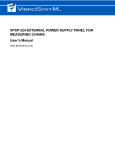
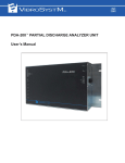
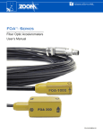
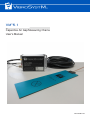
VM™5.1
Capacitive Air Gap Measuring Chains
User’s Manual
P/N: 9428-25M1A-100
Safety Information
The following manual contains information and warnings. They must be followed in order to keep the
instrument in a working condition and ensure safe operation.
Safety and Electrical Symbols
Warning - Danger - Identifies conditions or practices that could cause physical harm or
death.
Caution - Identifies conditions or practices that could result in a permanent loss of data or
damage the measuring chain and/or other equipment to which it is connected.
Important Information - Identifies important information, hints, and tips that must be read
and applied.
Safety Precautions
Warning - Danger
•
•
•
•
•
•
•
Caution
To use the described product correctly and safely, read and follow all safety instructions or
warnings that appear throughout this manual.
This product in intended to be used by qualified operators and maintenance personnel who
recognize shock hazards and are familiar with the safety precautions required to avoid possible
injury. Read and follow all installation, operation, and maintenance information before using this
product.
Use this product only as specified in this manual or the protection provided by this product
might be impaired.
When in doubt that safety protection has been impaired, make this product inoperative and
secure it against any unintended operation.
Use caution when working with voltage levels above 30 VAC RMS or 42 VDC. These voltage
levels are potential shock hazards.
Follow all generally accepted safety practices and procedures when working with or around
electricity.
Do not use this product in wet environments.
The VibroSystM logo, VM™, and LIN™ are registered trademarks or trademarks of VibroSystM Inc.
This manual is provided solely for guidance. VibrosystM Inc. takes no responsibility or liability for any damage caused by accidents, improper installation or
misuse. Liability is limited to the repair and/or replacement of defective products.
VibroSystM Inc. 2727 Jacques-Cartier E. Blvd, Longueuil, QC, Canada J4N 1L7 | Phone: 450 646-2157 | U.S. Toll-free Line: 800 663-8379
Email: [email protected] | www.vibrosystm.com
2
VM5.1 - User’s Manual
© 2015 VibroSystM Inc. All rights reserved
TABLE OF CONTENTS
1. VM5.1 MEASURING CHAIN OVERVIEW............................................................................
5
1.1 Description ..................................................................................................................................................
1.2 Main Unit Interventions ..............................................................................................................................
1.3 Sensor Installation Overview ......................................................................................................................
5
6
7
2. TRIAXIAL EXTENSION CABLE OVERVIEW......................................................................
8
2.1 Description ..................................................................................................................................................
2.2 Installation Overview ..................................................................................................................................
8
8
3. LIN-300 SERIES CONDITIONER OVERVIEW ....................................................................
9
3.1
3.2
3.3
3.4
3.5
3.6
3.7
Description ..................................................................................................................................................
Installation Overview ..................................................................................................................................
Connection ..................................................................................................................................................
M12 Connector Pinout ................................................................................................................................
Grounding the Signal Cable’s Shield..........................................................................................................
Output Signal Value....................................................................................................................................
Operation.....................................................................................................................................................
3.7.1 Boot Sequence....................................................................................................................................
3.7.2 LED Functionality..............................................................................................................................
VM5.1 - User’s Manual
9
9
10
11
11
12
13
13
13
3
4
VM5.1 - User’s Manual
1. VM5.1 MEASURING CHAIN OVERVIEW
1.1
Description
The VM5.1 measuring chains are used to measure an air gap in large rotating machines. The raw signal
picked up by the VM5.1 capacitive air gap sensor is sent to a LIN™-300 series conditioner through a triaxial
extension cable to be converted into a linearized 4 to 20 mA signal. The entire chain is then connected to an
acquisition unit through an M12 connector and signal cable.
VM5.1 Capacitive Air Gap Sensor
Integral
Cable
Grounding
Wire
Sensing
Face
Important Information
•
Because of the different measuring ranges covered by the VM5.1 sensors and LIN-300 series conditioner
locations, different types of extension cables and conditioners must be used. Refer to the table below for
different combinations.
VM5.1 Measuring Chain Combinations
LIN-300 Series Model
Extension Cable Type
Measuring Range
LIN-351-10S-5/50
10 m [33 ft] Type S*
5 to 50 mm [197 to 1969 mils]
LIN-351-10H-5/50
10 m [33 ft] Type H**
5 to 50 mm [197 to 1969 mils]
LIN-351-15H-5/35
15 m [49 ft] Type H
5 to 35 mm [197 to 1378 mils]
LIN-351-20H-5/35
20 m [66 ft] Type H
5 to 35 mm [197 to 1378 mils]
*Type S cable: regular operating temperature.
**Type H cable: high operating temperature.
Refer to product data sheet for detailed specifications.
VM5.1 - User’s Manual
5
Measuring Chain and Signal Cable Layout
VM5.1
Sensor
Integral
Cable
Triaxial Extension Cable
Grounding Wires
LIN-300 Series Conditioner
Grounding Wire
Signal Cable
1.2
•
•
•
•
6
M12 Connector
Main Unit Interventions
Epoxy resins and silicone will be used inside the unit.
A hole must be threaded in the stator core pressure plate to connect the integral cable’s grounding wire on
the sensor side.
A protection box (or more) must be installed outside the stator core to house the LIN conditioner(s).
Protective conduits must be routed throughout the unit to protect the cables.
VM5.1 - User’s Manual
1.3
Sensor Installation Overview
Important Information
•
VibroSystM technicians should be present during measuring chain installation and commissioning.
•
The sensor’s sensing face must be parallel to the target’s surface.
•
Sensors must ideally be glued against stator laminations so they can face the plane area of rotor poles,
usually beneath the second ventilation hole.
•
The integral cable must also be glued to the stator core and covered with silicon for protection.
Caution
•
•
•
•
•
If sensors are to be glued on a stator with protruding wedges, make sure to use VibroSystM spacers.
Grounding wires must NEVER be cut or altered.
Integral cables are factory calibrated and must NEVER be cut or altered.
Never exert traction on the integral cable or connector.
Do not apply paint or silicone on the sensor’s sensing face.
VM5.1 - User’s Manual
7
2. TRIAXIAL EXTENSION CABLE OVERVIEW
2.1
Description
Triaxial extension cables are the link between the VM5.1 sensor’s integral cable and the LIN-300 series
conditioner.
Triaxial Extension Cable
Male Connector
Female Connector
Grounding Lug
Grounding Lug
PV311014A
Before installing the extension cable, it is important to determine where the conditioner protection boxes
will be installed, keeping in mind the cable’s length.
The cable and connections must be protected by a combination of conduit, protective tubing, and heatshrinkable jackets.
•
•
Caution
•
•
•
Never install extension cables on high voltage components.
Extension cables are calibrated and must NEVER be cut or altered.
Never pull on the SMA connector to route the cables.
2.2
Installation Overview
1. Make sure the integral cable’s male connector is well
secured to the extension cable’s female connector.
Extension Cable Female Connector
2. Sensor and extension cable grounding wires must both
be connected to a grounded part of the machine.
Caution
Integral Cable Male Connector
8
VM5.1 - User’s Manual
•
A protective heat-shrinkable jacket must be installed
around the integral and extension cable’s connection
to protect it from debris and isolate it from the ground.
3. LIN-300 SERIES CONDITIONER OVERVIEW
3.1
Description
The LIN-300 series conditioners are signal conditioning units which, when paired with matching sensor and
extension cable, deliver a 4 to 20 mA linearized raw output signal. The triaxial extension cable is connected
to the conditioner through an SMA connector, while power input and signal output are provided by a signal
cable through an M12 connector.
LIN-300 Series Conditioner
3.2
Installation Overview
The LIN-300 must be installed in a properly grounded protection box and mounting panel.
The power/signal cable is limited to a maximum length of 300 m [984 ft].
Possible conditioner locations are limited by the length of the sensor’s integral cable.
•
•
•
Caution
•
It is recommended to use a VibroSystM protection box since it is equipped with vibration dampers and
offers excellent grounding. Using a generic box could affect the entire measuring chain’s performance.
VM5.1 - User’s Manual
9
3.3
Connection
1. Make sure the grounding lug is firmly secured to the LIN300’s grounding terminal.
Recommended torque: 1.7 Nm [15 in-lb]
Grounding Lug
2. Make sure the extension cable’s SMA connector is firmly
secured to the LIN-300’s SMA socket.
Recommended torque: 1.1 Nm [10 in-lb]
SMA Connector
3. Make sure the M12 connector is firmly secured in place.
Caution
•
M12 Connector
10
VM5.1 - User’s Manual
Grounding is achieved through the LIN-300’s four
installation screws.
3.4
M12 Connector Pinout
The illustration below shows the LIN-300’s M12 male connector pinout.
3
4
5
2
1
The cable provided by VibroSystM may be replaced by any cable having similar characteristics. The table
below shows the color codes, designations and specifications for VibroSystM’s signal cable.
M12 Connector Pin #
Corresponding Color Code
Specifications
1
Brown
Power Supply
+24 VDC
2
White
Current Output
4-20 mA (proportional to sensor’s full range)
3
Blue
Common
0V
4
Black
5
3.5
Designation
Not Used
Not Used
Grounding the Signal Cable’s Shield
The signal cable’s shield must also be grounded. It is important that the shield be grounded on one end only
to avoid creating a ground loop. If the M12 connector at the end of the signal cable is insulated from the shield,
the shield must then be grounded on the acquisition unit side. However, if the M12 connector at the end of
the signal cable is connected to the shield, connecting the signal cable to an already grounded LIN-300
conditioner will automatically ground the shield. In this case, the shield must not be grounded on the
acquisition unit side.
VM5.1 - User’s Manual
11
3.6
Output Signal Value
Once the sensor is connected, the LIN-300’s output signal value must be within the 3 to 22 mA range. The
output signal provides linear current throughout the entire measuring range. The distance value is obtained
by applying the following transfer formulas:
LIN-351-10S-5/50
•
•
Dmm = (Iout(mA) - 2.22) / 0.355
Dmils = (Iout(mA) - 2.22) / 0.00903
Over 4-20 mA Output
Over 4-20 mA Output
LIN-351-10H-5/50
•
•
Dmm = (Iout(mA) - 2.22) / 0.355
Dmils = (Iout(mA) - 2.22) / 0.00903
Over 4-20 mA Output
Over 4-20 mA Output
LIN-351-15H-5/35
•
•
Dmm = (Iout(mA) - 1.33) / 0.533
Dmils = (Iout(mA) - 1.33) / 0.01355
Over 4-20 mA Output
Over 4-20 mA Output
LIN-351-20H-5/35
•
•
12
Dmm = (Iout(mA) - 1.33) / 0.533
Dmils = (Iout(mA) - 1.33) / 0.01355
VM5.1 - User’s Manual
Over 4-20 mA Output
Over 4-20 mA Output
3.7
Operation
3.7.1 Boot Sequence
Once the sensor is connected, apply power to the LIN-300 and verify the 3-color LED indicator’s flash
sequence upon start-up. A normal boot sequence should be as follows:
One orange flash, followed by green flashes.
3.7.2 LED Functionality
Once the boot sequence is completed, the LED indicator will continue flashing green while the LIN-300 scans
the measuring chain. Once the scan is completed, the LED reflects the chain’s overall condition:
Continues Flashing Green: Indicates a normal operation
(Status OK).
Flashes Red: Indicates an error condition. Two flash
sequences are most likely to occur:
LED
Indicator
Error Condition #1: The LED turns on for one second,
followed by one brief flash. This means that the sensor
is not connected.
Error Condition #2: The LED turns on for one second,
followed by two brief flashes. This means that the
sensor’s distance to the target is below the minimum
detection range.
If a different LED sequence from the ones explained above appears on the LIN-300, please contact
VibroSystM.
VM5.1 - User’s Manual
13
14
VM5.1 - User’s Manual