1
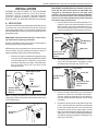
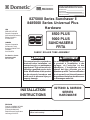
8275000 & 8485000 Series Universal Plus Hardware Installation Instructions
RECORD THIS INFORMATION FOR FUTURE
REFERENCE BEFORE INSTALLING THE UNIT:
Model Number
Serial Number
Date Purchased
Place of Purchase
USA
SERVICE OFFICE
Dometic Corporation
2320 Industrial Parkway
Elkhart, IN 46516
574-294-2511
CANADA
Dometic Corporation
46 Zatonski, Unit 3
Brantford, ON N3T 5L8
CANADA
519-720-9578
8275000 Series Sunchaser II
8485000 Series Universal Plus
Hardware
8500 PLUS
9000 PLUS
SUNCHASER II
FRTA
FABRIC ROLLER TUBE ASSEMBLY
For Service Center
Assistance Call:
800-544-4881
! WARNING
! AVERTISSEMENT
This manual must be read and understood before installation, adjustment, service, or maintenance
is performed. This unit must be installed by a qualified service technician. Modification of this product
can be extremely hazardous and
could result in personal injury or
property damage.
INSTALLATION
INSTRUCTIONS
REVISION
Form No. 3309802.027 8/06
(Replaces 3309802.019)
(French 3309803.025)
©2006 Dometic Corporation
LaGrange, IN 46761
Lire et comprendre ce manuel avant
de procéder à l'installation, à des
réglages, de l'entretien ou des
réparations. L'installation de cet
appareil doit être effectuée par un
réparateur qualifié. Toute modification
de cet appareil peut être extrêmement
dangereuse et entraîner des blessures
ou dommages matériels.
8275000 & 8485000
SERIES
HARDWARE
Important: Instructions must stay with unit.
Owner read carefully
1
8275000 & 8485000 Series Universal Plus Hardware Installation Instructions
SAFETY INSTRUCTIONS
This manual has safety information and instructions to help users eliminate or reduce the risk of
accidents and injuries.
RECOGNIZE SAFETY INFORMATION
!
This is the safety-alert symbol. When you see this
symbol in this manual, be alert to the potential for
personal injury.
Follow recommended precautions and safe operating instructions.
UNDERSTAND SIGNAL WORDS
A signal word , WARNING OR CAUTION is used
with the safety-alert symbol. They give the level of
risk for potential injury.
! WARNING indicates a potentially hazardous situation which, if not avoided, could result in
death or serious injury.
! CAUTION indicates a potentially hazardous situation which, if not avoided, may result in
minor or moderate injury.
CAUTION
used without the safety alert
symbol indicates, a potentially hazardous situation which, if not avoided, may result in property
damage.
Read and follow all safety information and instructions.
2
8275000 & 8485000 Series Universal Plus Hardware Installation Instructions
SPECIFICATIONS:
MODEL SERIES
8485000.401#
8275000.401#
Height Range
8485000.402# 8485000.405# 8485000.407#
8275000.402# 8275000.405# 8275000.407#
**8485000.408#
**8275000.408#
76" - 86"
64" - 76"
78" - 91"
94" - 107"
Main Arm Length
73"
61"
76"
92"
Short 61"
Tall 73"
Adjustable Arm Length
57"
57"
72"
72"
Short 57"
Tall 57"
Main Rafter Length
66"
54"
71"
71"
Short 54"
Tall 66"
32.5"
44.5"
53.5"
53.5"
Standard
Standard
Standard
Standard
8485000.501#
8485000.502#
Secondary Rafter Length
Duty*
MODEL SERIES
Height Range
8485000.507#
76" - 86"
64" - 76"
94” - 107"
Main Arm Length
73"
61"
92"
Adjustable Arm Length
57"
57"
72"
Main Rafter Length
66"
54"
71"
Secondary Rafter Length
32.5"
44.5"
53.5"
Duty*
Heavy
Heavy
Heavy
*Note: Standard Duty is used with 8500 and 9000 Awnings 21' and below.
Heavy Duty is used with 8500 and 9000 Awnings 22' and above.
**Note: Model 8485000.408# & 827500.408# has one Short Arm and one
Tall Arm. (8485000.408# Rain shed is in Tall Arm only.)
Replace # in part number with:
B = Polar White
H = Mende
R = Champagne
S = Satin
U = Black
V = Gold
3
Short 64" - 76"
Tall 76" - 86"
Short 44.5"
Tall 32.5"
Standard
8275000 & 8485000 Series Universal Plus Hardware Installation Instructions
INSTALLATION
Important: The 8485000 Series hardware is manufactured with the Rain Shed Feature (an adjustable arm
designed to automatically lower to the water shed
position). This arm can be placed on either the Right or
Left end of the Fabric Roller Tube Assembly (FRTA);
however, it is recommended that it is placed on the end
the farthest away from the door.
2. Carefully lay the fabric roller tube assembly on "V"
troughs or other well protected surface to prevent
fabric damage. Secure arm assemblies to the respective top castings using 1/4–20 x 1/2" hex. head
machine screws and 1/4" lock washers. See FIG. 3.
COVERED BY ONE OR MORE OF THE FOLLOWING
PATENTS: 4,188,964; 4,524,791; 5,351,736; 5,351,827;
5,383,346; 5,472,007; 5,,516,244; 5,566,918; 5,924,465;
5,732,756; 5,944,085; 6,006,810; 6,098,693; D353,473;
D366,763; D395,170; D428,266; D429,894; others pending.
A. APPLICATION
The standard A&E awning is designed and intended for use
on motorhomes, mini-motorhomes, 5th wheels and travel
trailers with straight sides. For curved sides, please see the
separate Hardware List in the Dealer Service Manual for the
appropriate model.
FIG. 3
Important: Read and understand ALL of the follow-
Top Casting
Lock Lever
ing steps before beginning installation.
Cotter Pin
Dometic Corporation reserves the right to modify appearances and specifications without notice.
Top Mounting
Bracket
Main Arm
A&E awnings can be installed by one person with brief help
from two others. Use the following procedure to assure a
properly installed, and properly functioning awning.
1/4-20 x 1/2" Hex
Head Machine
Screw
1. When the awning is mounted above a square corner
entry door, a door roller and guard (NOT INCLUDED)
must be installed per FIG. 1 and FIG. 2, to reduce the
potential of damage to the fabric. Rounded doors
may not require a door roller if the door will not
damage the fabric.
3. After attaching both arms, rotate the Safe-T-LockTM
lever to the roll down position. Straighten, remove
and discard left cotter pin only. See FIG. 3A.
FIG. 3A
Wheel Above Door
1/4" - 3/8"
Top Casting
Cotter Pin
FIG. 1
Top Mounting
Bracket
Entry
Door
1/4-20 x 1/2" Hex
Head Machine
Screw
Position Wheel
Directly Over Edge
Of Door
4. Remove the rafter assemblies from the hardware
and store in a place for re-installation after Step 7.
This will reduce the opportunity for the rafters to
become unlatched and scratch the vehicle during
installation.
Note: If installing the awning over a square door the A&E
(Single) Door Roller Kit is part number 830304 and a carton
of 50 is 830304.003.
5. Prepare the awning rail to accept the awning roller
cover. Select the end from which the awning shall
be fed, then widen that end of the rail with a flat
screwdriver and file off any sharp edges. Unwind
fabric one revolution before feeding awning fabric into
awning rail. This will allow enough space between
side wall and awning hardware to feed fabric into
awning rail. See FIG. 4.
FIG. 2
Door Edge
Guard
4
8275000 & 8485000 Series Universal Plus Hardware Installation Instructions
Find a solid structure in the coach wall to anchor the
#14 X 3" hex head screw. The relationship of the
solid structure with the awning rail will determine the
position of the top mounting brackets. The top
mounting bracket can be placed over, on or under
the awning rail as shown in FIG. 7, 7A, & 7B. If the
top mounting bracket cannot touch the side of the
coach because the awning rail is too wide, a stand
off is available. This will allow the top bracket to clear
the wider awning rail. Part number for the (one) stand
off is 3109623.003 and 50 count package
3109623.550
FIG. 4
Before
After
6. With one person grasping each support arm, carefully lift the entire assembly upright. Keep the two
arm assemblies parallel to each other to avoid
damage due to twisting. Carry the awning to the
prepared awning rail end. See FIG. 5.
Awning
Rail
Important: If top bracket must be mounted over top
rail as shown in Figure 7B, care should be taken to note
radius roof construction. If radius cap molding is rubber, there could be the possibility for water leaks if top
bracket is fastened against the rubber molding. In
those applications, it is recommended that the top leg
of the bracket be fastened against the awning rail
flange as shown in FIG. 7.
Fabric Roller Tube
Assembly
Arm Assembly
Note: Top rafter bracket assembly is independent of the main
support arm assembly.
FIG. 5
FIG. 7
Feed the awning into the awning rail while standing
on a stepladder, (third person) while two carry the
awning assembly to the desired position.
7. Install Top Brackets.
After the complete awning assembly has been
threaded into the awning rail, check to be sure that
its position allows for solid mounting of the top and
bottom brackets and that support arms are in
desired location (not restricting use of doors, access doors, windows, etc.). See FIG. 6
Reinstall rafter assemblies into the hardware.
Mount Top Bracket
Over Awning Rail
#14 x 3" Hex
Head Screw
Awning
Rail
Top Pivot
Rafter
FIG. 7A
FIG. 6
#14 x 3” Hex
Head Screw
Awning Rail With
Drip Channel
Mount Top Bracket
Below Awning
Rail
Top Pivot
The top mounting bracket can be placed in several
different positions in relationship with the awning
rail. Some awning rails have a drip channel to catch
water as it runs off the roof and drain it to the front or
rear of the coach.
Rafter
5
8275000 & 8485000 Series Universal Plus Hardware Installation Instructions
7. Install Bottom Brackets. Snap the patio foot on the
bottom of the inner arm into the bottom bracket. See
FIG. 8. Insure the arm top casting is resting on the
top pivot. Lift the main arm handle and slide the inner
arm up to the desired mounting position. Select the
best supporting structure, i.e. mount directly into
the floor line, molding, etc.
Awning Rail With
Drip Channel
FIG. 7B
#14 x 3" Hex
Head Screw
Mount Top Bracket
Over Awning Rail
Mark position of bottom bracket holes. Predrill two
3/16" diameter holes through the marked locations.
(Drill 7/32" diameter hole if into steel). Apply silicone
sealant to screw threads and where the screws
enter the coach. Secure the bottom bracket to the
coach using #14 hex head screws. See FIG. 8.
Repeat for other side.
Top Pivot
Rafter
CAUTION
Note: If installing over a molding, A&E Standoff Kit
3104781.004 must be used. See FIG. 9.
After the top bracket has been mounted, do
not pull the bottom of the arm assembly away
from the side of the vehicle, with the Safe-TLockTM in the roll-up position. Damage to the
torsion lock can occur, which may cause the
torsion to malfunction.
FIG. 9
Molding
Bottom Wall
Bracket
Align top bracket directly behind and centered with
the main support arm.
Lift the arm handle (releasing lock button) and
CAREFULLY extend the inner arm to the ground to
support the awning.
Standoff
Pull the main support arm away from the top bracket
and rafter. Mark the top bracket position and predrill
the two 3/16" diameter holes (drill 7/32" diameter if
into steel). Install top bracket with two #14 X 3" hex.
head screws. See FIGS. 7, 7A, & 7B. Apply silicone
sealant to screw threads and where the screws
enter the coach. Place main support arm on the top
pivot. Repeat for the other side.
CAUTION
This step is essential for the proper functioning of all A&E Awnings.
8. Install Stop Bolt or Clip.
a. 8275000 Standard Arm (Go to step “b” if installing 8485000 model.)
Using the lift handle, RAISE THE MAIN ARM
UP BY ONE HOLE ONLY.
Bottom
Wall
Bracket
FIG. 8
Install the 5/16-18 x .50" bolt inside the inner
arm, through the hole closest to the bottom of
the main arm. Secure with a 5/16"-18 lock
washer and acorn nut. See FIG. 10. Repeat step
“a.” on opposite side.
THE MAIN SUPPORT ARM SHOULD NOW
CLEAR THE TOP PIVOT BY 1/2" WHEN THE
AWNING CLOSES. SEE FIGS. 7, 7A, & 7B.
Patio
Foot
Lift And Snap Patio Foot Into
Bottom Wall Bracket
6
8275000 & 8485000 Series Universal Plus Hardware Installation Instructions
FIG. 10A
FIG. 10
Stop Clip
Main Arm
3/8" Dia. Hole
Closest To
Main Arm
Drive In
Screw
To Hold
Main Arm
Adjustable
Arm
5/16" - 18 Bolt and
Lock Washer
STANDARD SIDE
WATER SHED SIDE
Inner Arm
5/16" - 18 x 1"
Shoulder Bolt
b. The model 8485000 hardware has the water
dump feature. The stop is a slide attached to the
main arm with a #6-20 x .44" screw. It performs
the same function as the stop bolt mentioned in
“8a”. Position the arm as directed in step “a”.
Slide stop clip down the main arm until it rests
on top of the adjustable arm. Using a pencil,
draw a line on the hardware for the slider stop
location. Open the awning and drive the #6-20 x.
44" self drilling screw through the hole in the clip
and the hardware. Install the clip on both main
arms.
c. If the water shed adjustable arm is telescoped
so far into the main arm that the lift handle does
not engage the adjustable arm, it may be
necessary to prop the main arm so that the
distance between its lower edge to the bottom
foot is consistent with the non-water shed
(standard) side. A block of wood or any other
non-marring material my be used to maintain
the proper distance until the stop clip is secured
using the #6-20 x .44" self-drilling screw as
described in Step “b”. See Figure 10A.
9. Release Preset Tension.
Check to see if the Safe-T-LockTM lever is in the roll
down position. Remove right cotter pin that is
holding factory preset tension. The cotter pin is
found in the roller tube end cap. See FIG. 11. For
easier removal, twist the roller tube as if unrolling
awning by pulling the bottom of the tube toward
yourself while pulling on cotter pin. Discard pin.
Stop Clip Shown Against
Edge of Adjustable Arm
Upper Edge of Adjustable
Arms May or May Not Match
From One Side to the Other
This Dim Must Match
For Both Sides of
Hardware
Block of Wood or Other
Non-Marring Material
Stop Bolt / Nut Shown
Installed in Standard
Side
7
8275000 & 8485000 Series Universal Plus Hardware Installation Instructions
! WARNING
FIG. 12
When cotter pins are removed from the torsion, spring tension, will attempt to close the
awning. Keep body clear of hardware and
roller tube.
While holding the pull strap, move the Safe-T-Lock
lever to the roll up position. The awning should now
roll up snugly against the vehicle side. See FIG. 11.
TM
FIG. 11
SAFE-T-LOCKTM
Lever Direction
Roll UP
FIG. 13
Roll
Down
End
Cap
Squeeze
Travel
Lock
Cotter
Pin
10. Secure Awning to Awning Rail. Open and close
awning a few times to allow for natural self adjustment of awning. Insure the arms are still positioned
directly in front of the top brackets. Secure by
installing a #6 x 1/2" Tek screw on each end. See
FIG. 12. Model 8485000 requires the stop to be
installed in the water dump arm, while awning is
open. See FIG. 10A.
Stop Clip
11. Operate awning according to the Operating Instructions to check that all parts function properly.
12. Secure Awning for Travel. For added security and
rattle-free travel, tighten rafter knobs, secure travel
latches and insure torsion lock is in the roll up
position. See FIGS. 11 & 13.
Travel
Lock
8