1
User’s Manual
Renesas Flash Programmer
Flash memory programming software
User’s Manual
All information contained in these materials, including products and product specifications,
represents information on the product at the time of publication and is subject to change by
Renesas Electronics Corp. without notice. Please review the latest information published by
Renesas Electronics Corp. through various means, including the Renesas Electronics Corp.
website (http://www.renesas.com).
www.renesas.com
Rev. 4.00 Jun. 2012
Notice
1.
Descriptions of circuits, software and other related information in this document are provided only to illustrate the operation of
semiconductor products and application examples. You are fully responsible for the incorporation of these circuits, software,
and information in the design of your equipment. Renesas Electronics assumes no responsibility for any losses incurred by you
or third parties arising from the use of these circuits, software, or information.
2.
Renesas Electronics has used reasonable care in preparing the information included in this document, but Renesas Electronics
does not warrant that such information is error free. Renesas Electronics assumes no liability whatsoever for any damages
incurred by you resulting from errors in or omissions from the information included herein.
3.
Renesas Electronics does not assume any liability for infringement of patents, copyrights, or other intellectual property rights of
third parties by or arising from the use of Renesas Electronics products or technical information described in this document. No
license, express, implied or otherwise, is granted hereby under any patents, copyrights or other intellectual property rights of
Renesas Electronics or others.
4.
You should not alter, modify, copy, or otherwise misappropriate any Renesas Electronics product, whether in whole or in part.
Renesas Electronics assumes no responsibility for any losses incurred by you or third parties arising from such alteration,
modification, copy or otherwise misappropriation of Renesas Electronics product.
5.
Renesas Electronics products are classified according to the following two quality grades: “Standard” and “High Quality”. The
recommended applications for each Renesas Electronics product depends on the product’s quality grade, as indicated below.
“Standard”:
Computers; office equipment; communications equipment; test and measurement equipment; audio and visual
equipment; home electronic appliances; machine tools; personal electronic equipment; and industrial robots etc.
“High Quality”: Transportation equipment (automobiles, trains, ships, etc.); traffic control systems; anti-disaster systems; anticrime systems; and safety equipment etc.
Renesas Electronics products are neither intended nor authorized for use in products or systems that may pose a direct threat to
human life or bodily injury (artificial life support devices or systems, surgical implantations etc.), or may cause serious property
damages (nuclear reactor control systems, military equipment etc.). You must check the quality grade of each Renesas
Electronics product before using it in a particular application. You may not use any Renesas Electronics product for any
application for which it is not intended. Renesas Electronics shall not be in any way liable for any damages or losses incurred
by you or third parties arising from the use of any Renesas Electronics product for which the product is not intended by Renesas
Electronics.
6.
You should use the Renesas Electronics products described in this document within the range specified by Renesas Electronics,
especially with respect to the maximum rating, operating supply voltage range, movement power voltage range, heat radiation
characteristics, installation and other product characteristics. Renesas Electronics shall have no liability for malfunctions or
damages arising out of the use of Renesas Electronics products beyond such specified ranges.
7.
Although Renesas Electronics endeavors to improve the quality and reliability of its products, semiconductor products have
specific characteristics such as the occurrence of failure at a certain rate and malfunctions under certain use conditions. Further,
Renesas Electronics products are not subject to radiation resistance design. Please be sure to implement safety measures to
guard them against the possibility of physical injury, and injury or damage caused by fire in the event of the failure of a Renesas
Electronics product, such as safety design for hardware and software including but not limited to redundancy, fire control and
malfunction prevention, appropriate treatment for aging degradation or any other appropriate measures. Because the evaluation
of microcomputer software alone is very difficult, please evaluate the safety of the final products or systems manufactured by
you.
8.
Please contact a Renesas Electronics sales office for details as to environmental matters such as the environmental compatibility
of each Renesas Electronics product. Please use Renesas Electronics products in compliance with all applicable laws and
regulations that regulate the inclusion or use of controlled substances, including without limitation, the EU RoHS Directive.
Renesas Electronics assumes no liability for damages or losses occurring as a result of your noncompliance with applicable laws
and regulations.
9.
Renesas Electronics products and technology may not be used for or incorporated into any products or systems whose
manufacture, use, or sale is prohibited under any applicable domestic or foreign laws or regulations. You should not use
Renesas Electronics products or technology described in this document for any purpose relating to military applications or use
by the military, including but not limited to the development of weapons of mass destruction. When exporting the Renesas
Electronics products or technology described in this document, you should comply with the applicable export control laws and
regulations and follow the procedures required by such laws and regulations.
10. It is the responsibility of the buyer or distributor of Renesas Electronics products, who distributes, disposes of, or otherwise
places the product with a third party, to notify such third party in advance of the contents and conditions set forth in this
document, Renesas Electronics assumes no responsibility for any losses incurred by you or third parties as a result of
unauthorized use of Renesas Electronics products.
11. This document may not be reproduced or duplicated in any form, in whole or in part, without prior written consent of Renesas
Electronics.
12. Please contact a Renesas Electronics sales office if you have any questions regarding the information contained in this document
or Renesas Electronics products, or if you have any other inquiries.
(Note 1) “Renesas Electronics” as used in this document means Renesas Electronics Corporation and also includes its majorityowned subsidiaries.
(Note 2) “Renesas Electronics product(s)” means any product developed or manufactured by or for Renesas Electronics.
(2012.4)
How to Use This Manual
Target Readers
This manual is intended for users who use the flash programmer when designing and
developing a system using a Renesas Electronics on-chip flash memory
microcontroller.
Purpose
This manual is intended to give users an understanding of the basic specifications
and correct use of the Renesas flash programmer.
Organization
This manual includes the following sections.
• Overview
• Installation
• Basic operation (Basic mode)- RL78, 78K, V850 -
<R>
• Basic operation (Basic mode)- RX • Function details (Basic mode)- RL78, 78K, V850 • Function details (Basic mode)- RX –
• Function details (Full mode)- RL78, 78K, V850 –
• Function details (Full mode)- RX –
• Script execution function - RL78, 78K, V850 –
• Script execution function - RX –
• Unique code embedding function
• Troubleshooting
• Cautions
• Messages
• Supplementary information
How to Read This Manual
It is assumed that the readers of this manual have general knowledge of electricity,
logic circuits, and microcontrollers.
In the explanations of the operation of the
applications, it is also assumed that the readers have sufficient knowledge of
TM
Windows .
For the usage and terminology of Windows, see each Windows
manual.
To understand the overall operation of the Renesas flash programmer
→ Read this manual according to the CONTENTS.
To know the basic specifications, usages, and usage examples of the hardware
→ See the E1/E20 User’s Manual or QB-MINI2 User’s Manual.
The mark <R> shows major revised points. The revised points can be easily
searched by copying an “<R>” in the PDF file and specifying it in the “Find what:” field.
Conventions
Note: Footnote for item marked with Note in the text.
Caution: Information requiring particular attention
Remark: Supplementary information
Numeral representation:
Binary ... xxxx or xxxxB
Decimal ... xxxx
Hexadecimal ... 0XXXXX or xxxxH
“
[
”:
Any character or item on the screen that can be selected or input
:
Name of button
]:
Name of commands, dialog boxes, options, or areas on the screen
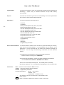
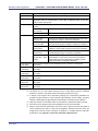
Terminology
The meanings of the terms used in this manual are as follows:
Term
Meaning
RFP
Abbreviation of the flash memory programming software, Renesas Flash
Programmer
E1/E20
Abbreviation of the E1 emulator / E20 emulator
MINICUBE2
Nickname used for the main unit of QB-MINI2, the on-chip debug emulator
with programming function
Tool used
General term for the tool used by the customer, which is E1, E20, or
MINICUBE2.
Utility
Software used for self-diagnosis of the tool used and to update the
MINICUBE2 firmware.
Target microcontroller
The Renesas Electronics on-chip flash memory microcontroller used by the
user
Target system
User-designed board on which the target microcontroller is mounted
Note 1
<R>
Program adapter
Conversion adapter used to write programs to the target microcontroller
Device information file
Device information files contain parameter information required for writing
programs to the flash memory in the target microcontroller. These files have
the extension *.prm, *.pr5, or *.fcf. Do not change the data in the device
information files. If the data is changed, RFP might not operate properly.
Workspace file
The workspace is where projects are stored. There is always at least one
project in the workspace. Some workspaces allow multiple projects to be
registered.
In RFP, workspace files have the extension *.rws.
Project file
Project files store the data required to write programs. In RFP, a project file
stores the settings related to the programming environment, such as target
microcontroller settings and command option specifications. In RFP, project
files have the extension *.rpj.
OCD security ID
A security feature related to on-chip debugging of a microcontroller.
Signature
Information about the microcontroller (such as the microcontroller name and
firmware version)
Flash options
General term for security settings, rewrite protection settings, reset vector
handling function settings, option byte settings, and on-chip debug security ID
settings
Option data
General term for flash options, wide-voltage mode, and full-speed mode
HEX file
Program file without option data
HCUHEX file
A program file that integrates option data and that is generated by using the
HEX Consolidation Utility (HCU), which is used to generate ROM code for
flash memory products whose flash memories are pre-written by Renesas
Electronics.
Note 2
Notes 1. The program adapter is a product of Naito Densei Machida Mfg. Co., Ltd.
If you have any questions about the FA adapter board, contact Naito Densei Machida
Mfg. Co., Ltd. (Tel: +81-42-750-4172).
2. The functions that can be used differ depending on the target microcontroller.
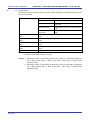
Term
Program file
Meaning
The program file refers to the file that contains the program to be written to the
microcontroller. The following program file formats are supported by RFP
when writing to an RL78, 78K0, 78K0R, or V850 microcontroller:
a. HEX files in Intel HEX format
b. HCUHEX files in Intel HEX format
c. HEX files in Motorola S format
d. HCUHEX files in Motorola S format
The following program file formats are supported by RFP when writing to an RX
microcontroller:
a. HEX files in Intel HEX format
b. HEX files in Motorola S format
Caution An empty area will be supplemented with FFH.
rfp.ini
This file is where the RFP settings are saved. The settings are saved when
RFP is terminated.
Location of file when using Windows XP:
C:\Documents and Settings\user-name\Local Settings\Application
Data\Renesas Flash Programmer\RFP-version
Location of file when using Windows Vista or Windows 7:
C:\Users\user-name\AppData\Roaming\Renesas Flash
Programmer\RFP-version
COMx
COMx is a serial interface port incorporated in the host machine.
When writing data to the target system by using the serial interface incorporated
in the host machine, select COMx as the tool used. Any value from 1 to 256
can be specified for x.
<R>
USB Direct
USB Direct is a method to write in the microcontroller in the USB boot mode by
using the USB interface port of the host machine.
When writing data by using the USB interface of the host machine, select USB
Direct as the tool used.
User/data area
Target area of the flash memory to which the program file is written.
For the RL78, 78K0, 78K0R, and V850: Code flash and data flash
For the RX: User mat and data mat
User boot area
Target area of the flash memory to which the program file is written.
For the RL78, 78K0, 78K0R, and V850: None
For the RX: User boot mat
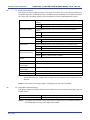
<R>
<R>
Basic mode
This mode is mainly for writing in mass production, and the focus is on basic
rewriting processing.
Full mode
The full mode is mainly for the use of microcontrollers in development, and
facilitates the control of multiple projects and the checking of setting
information.
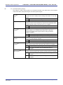
Related documents
When using this manual, also refer to the following documents.
The related documents indicated in this publication may include preliminary versions.
However, preliminary versions are not marked as such.
Documents related to development tools
Document name
Document number
Renesas Flash Programmer Flash Memory Programming Software
This manual
E1 Emulator R0E000010KCE00 E20 Emulator R0E000200KCT00
R20UT0398E
QB-MINI2 On-Chip Debug Emulator with Programming Function
R20UT0449E
MINICUBE2 Diagnosis Tool
U18588E
Note The related documents listed above are subject to change without notice.
Be sure to use the latest version of each document for designing, etc.
All trademarks and registered trademarks are the property of the respective owner.
CONTENTS
CHAPTER 1 OVERVIEW ..........................................................................................10
1.1
1.2
1.3
1.4
1.5
1.6
Features...................................................................................................................................10
Writing Quality ........................................................................................................................10
Supported Microcontrollers ..................................................................................................10
System Overview ....................................................................................................................11
Operating Environment..........................................................................................................12
1.5.1
Hardware environment ...............................................................................................12
1.5.2
Software environment.................................................................................................12
Handling of HCUHEX Files ....................................................................................................13
CHAPTER 2 INSTALLATION ...................................................................................14
2.1
2.2
2.3
Installation...............................................................................................................................14
2.1.1
Notes on installation ...................................................................................................15
Uninstallation ..........................................................................................................................16
Updating RFP and Firmware .................................................................................................16
CHAPTER 3 BASIC OPERATION (BASIC MODE) - RL78, 78K, V850 - ...................17
CHAPTER 4 BASIC OPERATION (BASIC MODE) - RX - ........................................25
CHAPTER 5 FUNCTION DETAILS (BASIC MODE) - RL78, 78K, 850 - ...................36
5.1
5.2
Introduction.............................................................................................................................36
Starting up ...............................................................................................................................36
5.2.1
[Welcome!] dialog box .............................................................................................37
5.2.2
[Create new workspace] dialog box .......................................................................38
5.2.3
[Communication Interface] dialog box...................................................................39
5.2.4
[Frequency] dialog box ............................................................................................40
5.2.5
[Power Supply] dialog box ......................................................................................43
5.2.6
[Project Settings] dialog box...................................................................................45
5.2.7
Open latest workspace ............................................................................................45
5.2.8
Open workspace .......................................................................................................46
5.3 Main Window...........................................................................................................................47
5.4 Menu Bar .................................................................................................................................48
5.4.1
[File] menu ................................................................................................................48
5.4.2
[Tool] menu ...............................................................................................................50
5.4.3
[Microcontroller] menu ............................................................................................51
5.4.4
[Help] menu ...............................................................................................................65
5.5 [Microcontroller] Area ............................................................................................................65
5.6 [Program File] Area ................................................................................................................66
5.7 [Command] Area.....................................................................................................................66
5.8 Start Button .............................................................................................................................67
5.9 Status Bar ................................................................................................................................67
5.10 Output Panel ...........................................................................................................................68
5.11 Clear Output Panel Button.....................................................................................................68
CHAPTER 6 FUNCTION DETAILS (BASIC MODE) - RX -.......................................69
6.1
6.2
Introduction.............................................................................................................................69
Starting up ...............................................................................................................................69
6.2.1
[Welcome!] dialog box .............................................................................................70
6.2.2
[Create a new workspace] dialog box ....................................................................71
6.2.3
[Communication Interface] dialog box...................................................................72
6.2.4
[Power Supply] dialog box ......................................................................................73
6.2.5
[Mode Pin at Connection] dialog box .....................................................................74
6.2.6
[Connection and Query] dialog box .......................................................................75
6.2.7
[Frequency] dialog box ............................................................................................77
6.2.8
[Baud Rate] dialog box ............................................................................................79
6.2.9
[Project Settings] dialog box...................................................................................80
6.2.10 Open latest workspace ............................................................................................81
6.2.11 Open workspace .......................................................................................................81
6.3 Main Window...........................................................................................................................83
6.4 Menu Bar .................................................................................................................................84
6.4.1
[File] menu ................................................................................................................84
6.4.2
[Tool] menu ...............................................................................................................86
6.4.3
[Microcontroller] menu ............................................................................................87
6.4.4
[Help] menu ...............................................................................................................98
6.5 [Microcontroller] Area ............................................................................................................98
6.6 [Program File] Area ................................................................................................................99
6.7 [Command] Area.....................................................................................................................99
6.8 Start Button ...........................................................................................................................100
6.9 Status Bar ..............................................................................................................................100
6.10 Output Panel .........................................................................................................................101
6.11 Clear Output Panel Button...................................................................................................102
CHAPTER 7 FUNCTION DETAILS (FULL MODE) - RL78, 78K, V850 -.................103
7.1
7.2
7.3
7.4
7.5
7.6
7.7
7.8
7.9
Introduction...........................................................................................................................103
Starting up .............................................................................................................................103
Main Window.........................................................................................................................104
Menu Bar ...............................................................................................................................105
7.4.1
[File] menu ..............................................................................................................105
7.4.2
[Tool] menu .............................................................................................................106
7.4.3
[Microcontroller] menu ..........................................................................................107
7.4.4
[Help] menu .............................................................................................................108
Tool Bar .................................................................................................................................108
[Workspace Tree] Panel .......................................................................................................109
[Project Settings] Panel .......................................................................................................110
Output Panel .........................................................................................................................111
Status Bar ..............................................................................................................................112
CHAPTER 8 FUNCTION DETAILS (FULL MODE) - RX -.......................................113
8.1
8.2
8.3
8.4
Introduction...........................................................................................................................113
Starting up .............................................................................................................................113
Main Window.........................................................................................................................114
Menu Bar ...............................................................................................................................115
8.4.1
[File] menu ..............................................................................................................115
8.4.2
[Tool] menu .............................................................................................................115
8.5
8.6
8.7
8.8
8.9
8.4.3
[Microcontroller] menu ..........................................................................................116
8.4.4
[Help] menu .............................................................................................................120
Tool Bar .................................................................................................................................120
[Workspace Tree] Panel .......................................................................................................121
[Project Settings] Panel .......................................................................................................122
Output Panel .........................................................................................................................123
Status Bar ..............................................................................................................................124
APPENDIX A MESSAGES......................................................................................146
A.1
A.2
A.3
A.4
Message Format ...................................................................................................................146
Messages Displayed in Internal Error, Fatal Error, Selection, and
Warning Dialog Boxes - Common - ....................................................................................147
Messages Displayed in Fatal Error, Selection, and Warning Dialog Boxes
- RL78, 78K, V850 - ...............................................................................................................149
Messages Displayed in Fatal Error, Selection, and Warning Dialog Boxes - RX -.........154
APPENDIX B SUPPLEMENTARY INFORMATION................................................161
Renesas Flash Programmer
Flash memory programming software
R20UT0599EJ0400
Rev. 4.00
2012.06.29
CHAPTER 1 OVERVIEW
<R> Renesas Flash Programmer (hereafter referred to as RFP) is software that erases, writes, and verifies programs on the
target system or program adapter on which a Renesas Electronics single-chip microcontroller with on-chip flash memory is
mounted by using an E1 emulator (hereafter referred to as E1), E20 emulator (hereafter referred to as E20), or the on-chip
debug emulator with programming function, QB-MINI2 (hereafter referred to as MINICUBE2), or a serial interface.
1.1
Features
• Writing controlled by the host machine
• Graphical user interface (GUI) specific to writing
• Writing settings can be saved in a workspace file
• Microcontroller-specific information required for writing is included in the product package as a device information file
<R> • Two types of writing operation windows (Basic mode and Full mode)
• Execution of scripts
• Embedding of unique codes
1.2
Writing Quality
Thoroughly confirm, verify and evaluate the following points before using RFP, in order to improve the writing quality.
• Design circuits as described in the user’s manual for the target microcontroller, E1, E20, and MINICUBE2.
• Use the microcontroller and RFP as described in the user’s manual of the target microcontroller, RFP, E1, E20, and
MINICUBE2.
• Make sure that the power supplied to the target microcontroller is stable.
1.3
Supported Microcontrollers
Microcontrollers supported by RFP are listed on the following websites:
• Japanese:
http://japan.renesas.com/rfp
• English:
http://www.renesas.com/rfp
R20UT0599EJ0400 Rev. 4.00
2012.06.29
Page 10 of 200
Renesas Flash Programmer
1.4
CHAPTER 1 OVERVIEW
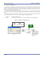
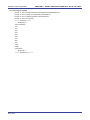
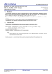
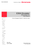
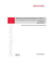
System Overview
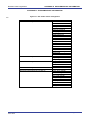
An overview of the RFP system is illustrated in the following diagram.
Figure 1-1. RFP Connection Image
E1
ホ ス トpackage
・マ
Product
シ
RFP
Targe system
Device information file
Target cable
USB cable
USB driver
E20
Utility
Workspace file
<R>
Program adapter
Project file
MINICUBE2
Program file
Scrip file
Unique code file
Serial cable (RS-232C)
rfp.ini
Note
USB cable (USB Direct)
Targe systemNote
To write data to the target system by using the serial interface incorporated in the host machine, a writing circuit
is required in the target system. See the sample circuit shown on the following websites:
• Japanese: http://japan.renesas.com/rfp
• English:
Remark
http://www.renesas.com/rfp
Do not modify or delete the folder and file configuration of the RFP. For the folder and file configuration, refer to
Figure B-1. RFP Folder and File Configuration in APPENDIX B.
RFP operation overview
The following operations can be performed by using RFP. The settings on the host machine are saved in an rfp.ini file.
• Creating, saving, and reading workspace files
• Reading program files and device information files
• Target command execution
• Checksum calculation for program files
<R> • Creating and saving multiple project files in workspace files (only full mode)
• Executing script commands
• Embedding unique codes
R20UT0599EJ0400 Rev. 4.00
2012.06.29
Page 11 of 168
Renesas Flash Programmer
1.5
CHAPTER 1 OVERVIEW
Operating Environment
This section explains the following items with respect to the operating environment:
• Hardware environment
• Software environment
1.5.1
Hardware environment
(1) Host machine
TM
• PC/AT
compatible
• Processor: 1 GHz or higher (RFP can be used with hyperthreaded and multi core CPUs)
®
• Main memory: 1 GB or more (2 GB or more when using 64-bit Windows 7 ); 2 GB or more recommended
• Display: Resolution of 1,024 x 768 or higher and 65,536 or more colors
• Interface: USB 2.0 (when using E1, E20, MINICUBE2, USB Direct)
Serial interface (RS-232C) (when using COMx)
(2) Tools used
• E1
• E20
• MINICUBE2
1.5.2
Software environment
• Windows XP (32-bit only)
• Windows Vista (32-bit and 64-bit)
• Windows 7 (32-bit and 64-bit)
• Microsoft .NET Framework 3.5 SP1
• Microsoft Visual C++ 2008 SP1 Redistributable Package (x86)
• Internet Explorer 6.0 or later
R20UT0599EJ0400 Rev. 4.00
2012.06.29
Page 12 of 168
CHAPTER 1 OVERVIEW
Renesas Flash Programmer
1.6
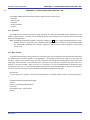
Handling of HCUHEX Files
An HCUHEX fi le i s re quired f or o rdering flash memory p roducts w hose f lash me mories are p re-written b y Re nesas
Electronics. After being generated by the HEX Consolidation Utility (HCU), operation based on the HCUHEX file must be
verified by using the flash memory programmer. Because RFP handles the HCUHEX file as master data, the user can
check the settings specified for writing and option data.
Some RL78, 78K0, 78K0R, and V850 m icrocontrollers support HCUHEX files. If a m icrocontroller supports HCUHEX
files, it is written in the user’s manual of the microcontroller. (SH, RX, and R8C m icrocontrollers do not support HCUHEX
files.)
For details, see the description on each feature in this manual. For details about the HCU, see the user’s manual of the
HCU or the target microcontroller. The HCU user’s manual is available on the following website:
<R>
• Japanese:
http://japan.renesas.com/hcu
• English:
https://secure-resource.renesas.com/micro/tool_reg/OdsListTool.do?code=640&lang=en
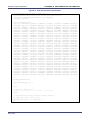
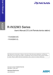
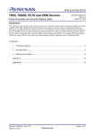
Figure 1-2. Example of Using RFP and HCUs
HEXfile
PG-FP5 parameter file
Target system
HCUHEX file
HCU
R20UT0599EJ0400 Rev. 4.00
2012.06.29
Verify operation
by using RFP
Send the HCUHEX file
when ordering a flash
memory product whose
flash memory is prewritten by Renesas
Electronics
Page 13 of 168
Renesas Flash Programmer
CHAPTER 2 INSTALLATION
CHAPTER 2 INSTALLATION
<R>
This chapter describes the following items:
• Installation
• Uninstallation
• Updating RFP and firmware
2.1
Installation
<R>
To install the product package (RFP, USB driver, and device information file), insert the CD into the host machine to
start the installer. Install as instructed by the installer program.
After the product package is installed, the folders are organized as follows:
C:\
\Program Files
Folder structure for which installation is specified
\Renesas Electronics
\Programming Tools
\Renesas Flash Programmer V1.01
\Renesas Flash Programmer V1.02
Folder where RFP, device information files, documents,
and utilities are stored
(Refer to Figure B-1. RFP Folder and File
Configuration in APPENDIX B.)
\CubeSuite+ Drivers
<R>
\E-SeriesUSB
Folder where the USB driver for E1 and E20 is stored
\MINICUBE2
Folder where the USB driver for MINICUBE2 is stored (32-bit Windows)
\USB Driver x64
Folder where the USB driver for MINICUBE2 is stored (64-bit Windows)
\HMSEUSB
Folder where the USB driver TYPE A for USB boot is stored
R20UT0599EJ0400 Rev. 4.00
2012.06.29
Page 14 of 168
Renesas Flash Programmer
2.1.1
CHAPTER 2 INSTALLATION
Notes on installation
(1) Multiple versions of RFP can be installed on a single host machine. Although we recommend using the latest
version of any development tool, leaving a previous version on your host machine and then installing the latest
version lets you easily switch the development environment.
(2) You might be asked to reboot your computer after installing the RFP. Be sure to close all other applications before
rebooting your computer.
(3) You must have administrator privileges to install the RFP.
(4) The RFP can only be installed in a folder that is named using ASCII characters. (Note that the 11 characters / * : <
> ? | " \ ; , and character strings that begin and end with a space cannot be used.) The RFP might not operate
correctly if installed in a folder that is named using other characters.
(5) The RFP cannot be installed from a network drive or on a network drive.
(6) The installer does not specify environment variable paths. If these paths are required, add them after installation.
(7) Internet Explorer 6.0 or higher, NET Framework, and Visual C++ runtime library must be installed on Windows on
<R>
which the RFP is installed.
(8) The following folders created after installation (including the files under the folders) contain files required for the
tools to operate. Do not delete them.
(Windows is the 32-bit edition and the system drive is C:)
C:\Program Files\Common Files\Renesas Electronics CubeSuite+\
(Windows is the 64-bit edition and the system drive is C:)
C:\Program Files\Common Files (x86)\Renesas Electronics CubeSuite+\
(9) To change the folder of the installed tools, uninstall all the CubeSuite+ related software and the programming GUI
for RFP, and install them again.
(10) In the environment where the CubeSuite+, RFP, E1, E20, MINICUBE2 and USB driver for USB Boot are installed,
the RFP, E1, E20, MINICUBE2 and USB driver for USB Boot are included in the target software of the CubeSuite+
integrated uninstaller. If you don’t want to delete them, remove them from the uninstallation targets.
R20UT0599EJ0400 Rev. 4.00
2012.06.29
Page 15 of 168
Renesas Flash Programmer
2.2
<R>
CHAPTER 2 INSTALLATION
Uninstallation
To uninstall the RFP package (RFP, USB driver, and device information file), use “Add or Remove Programs” (or
“Programs and Features”) on the Control Panel. The CubeSuite+ integrated uninstaller can also be used to uninstall the
RFP package.
2.3
Updating RFP and Firmware
The firmware is a program embedded in the microcontroller for controlling E1, E20, or MINICUBE2. Updating RFP and
the firmware enables the following:
• Addition of newly supported functions or microcontrollers
• Correction of restrictions
For RFP and the firmware, use of the latest version is recommended to ensure correct operation of E1, E20, and
MINICUBE2.
<R>
The latest version of the firmware for RFP and MINICUBE2, and MINICUBE2 Diagnostic Tools can be checked and
obtained at the following websites:
Japanese: http://japan.renesas.com/rfp
English:
http://www.renesas.com/rfp
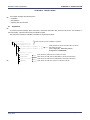
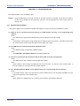
How to check the firmware version and configure and update your system are described below.
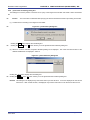
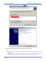
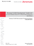
<R>
For E1 and E20, check that RFP has the correct E1 and E20 firmware versions. If the firmware does not match, the
[Renesas Flash Programmer] dialog box will open. Click the Yes button to update.
<R>
Figure 2-1. Updating Firmware
For MINICUBE2, see MINICUBE2 Diagnostic Tools User’s Manual (U18588E) for how to check the firmware version,
and configure and update your system.
R20UT0599EJ0400 Rev. 4.00
2012.06.29
Page 16 of 168
Renesas Flash Programmer
CHAPTER 3 BASIC OPERATION (BASIC MODE) - RL78, 78K, V850 -
CHAPTER 3 BASIC OPERATION (BASIC MODE) - RL78, 78K, V850 -
<R>
<R> This chapter describes the operation method by using the RL78 as the target microcontroller as an example to help you
understand a series of basic operations with the basic mode of RFP for the RL78, 78K, and V850. This chapter covers
how to start the system, execute the [Autoprocedure (E.P)] command, and write the target microcontroller.
• Series of operations described in this chapter:
The operating conditions are as follows:
Target microcontroller:
R5F100LE (RL78/G13)
Target system:
Program adapter
Tool used:
E1
<R>
Interface:
UART-ch0
<R>
Interface speed:
1,000,000 bps
<R>
Frequency:
None (internal oscillation clock used)
Power supply:
E1 (5.0 V)
Operating mode:
Chip
Flash option:
Not used
Operation option:
[Blank Check before Erase] enabled
The steps described in this chapter are as follows:
(1) Installation
(2) System connection
(3) Connection of target system
(4) Creation of workspace
(5) Selection of program file
(6) Execution of [Autoprocedure (E.P)] command
(7) System shutdown
(1) Installation
See CHAPTER 2 INSTALLATION and install in the host machine.
(2) System connection
Connect the USB connector of RFP to the USB port on the host machine using a USB cable.
(3) Connection of target system
Connect the target cable of the tool used to the target system.
Remark
Connect the target system before supplying VDD power from the target system.
R20UT0599EJ0400 Rev. 4.00
2012.06.29
Page 17 of 168
Renesas Flash Programmer
CHAPTER 3 BASIC OPERATION (BASIC MODE) - RL78, 78K, V850 -
(4) Creation of workspace
<R>
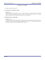
<1> On the taskbar, click the
Start
button, point to [All Programs], [Renesas Electronics Utilities],
[Programming Tools], [Renesas Flash Programmer Vx.xx], and then click [Renesas Flash Programmer
Vx.xx]. The [Welcome!] dialog box will open. Select [Create new workspace.], select [Basic mode], and
then click the Next button to open the [Create a new workspace] dialog box.
<R>
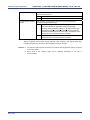
Figure 3-1. [Welcome!] Dialog Box
<2> In the [Using Target Microcontroller:] list box, select “R5F100LE”. Enter any text string (such as “sample” in
this case) in the [Workspace Name:] box, and specify any folder in the [Folder:] box.
<R>
Clicking the Next button displays the [Communication Interface] dialog box.
<R>
R20UT0599EJ0400 Rev. 4.00
2012.06.29
Figure 3-2. [Create new workspace] Dialog Box
Page 18 of 168
Renesas Flash Programmer
<R>
CHAPTER 3 BASIC OPERATION (BASIC MODE) - RL78, 78K, V850 -
<3> Select “E1” in the [Communication Interface] dialog box. For R5F100LE, the selection in the [Interface] list
box is fixed to “UART-ch0”.
Clicking the Next button displays the [Frequency] dialog box.
Figure 3-3. [Communication Interface] Dialog Box
<R>
<4> Select “1,000,000bps” from the [Interface Speed:] list box. For R5F100LE, the [Supply Oscillator] area is
fixed to “Internal-OSC”.
<R>
Clicking the Next button displays the [Power Supply] dialog box in the case of E1.
<R>
R20UT0599EJ0400 Rev. 4.00
2012.06.29
Figure 3-4. [Frequency] Dialog Box
Page 19 of 168
Renesas Flash Programmer
<R>
<5> Select the [Power target from the emulator] check box, and then select “5.0V” for [Supply voltage].
Clicking the Next button displays the [Project Settings] dialog box.
Figure 3-5. [Power Supply] Dialog Box
<R>
<R>
CHAPTER 3 BASIC OPERATION (BASIC MODE) - RL78, 78K, V850 -
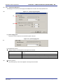
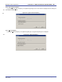
<6> The [Basic Settings] tab of the [Project Settings] dialog box shows the basic information about writing data.
Clicking the [Other Settings] tab of the [Project Settings] dialog box displays the [Other Settings] tab screen
of the [Project Settings] dialog box.
<R>
Figure 3-6. [Basic Settings] Tab of the [Project Settings] Dialog Box
<R>
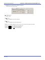
<7> The [Other Settings] tab of the [Project Settings] dialog box allows you to view and set advanced details of
writing data. “Chip” is the default value for [Operation mode] under the [Target] category, and the default
value for “Blank Check before Erase” in the [Command Options] category is “Valid”.
Clicking the Complete button saves the project file and displays the main window.
R20UT0599EJ0400 Rev. 4.00
2012.06.29
Page 20 of 168
Renesas Flash Programmer
<R>
CHAPTER 3 BASIC OPERATION (BASIC MODE) - RL78, 78K, V850 -
Figure 3-7. [Other Settings] Tab of the [Project Settings] Dialog Box
R20UT0599EJ0400 Rev. 4.00
2012.06.29
Page 21 of 168
Renesas Flash Programmer
CHAPTER 3 BASIC OPERATION (BASIC MODE) - RL78, 78K, V850 -
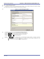
(5) Selection of program file
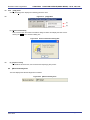
<1> Click the Browse… button in “User/Data area:” of the program file area to open the [Open File] dialog box.
Figure 3-8. Main Window
<R>
<2> Select “sample.hex” in the [Open File] dialog box, and then click the Open button to open the main window.
<R>
R20UT0599EJ0400 Rev. 4.00
2012.06.29
Figure 3-9. [Open File] Dialog Box
Page 22 of 168
Renesas Flash Programmer
CHAPTER 3 BASIC OPERATION (BASIC MODE) - RL78, 78K, V850 -
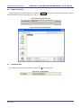
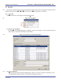
(6) Execute the [Autoprocedure (E.P)] command
<1> Click the [Microcontroller] menu and select the [Autoprocedure (E.P)] command. A check mark is then
placed on the left of the command, and the command is assigned to the Start button.
Figure 3-10. Main Window
<R>
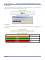
<2> After clicking the Start button, execute the following commands in the following order for R5F100LE: [Blank
Check] command, [Erase] command (if there are no blanks), and [Program] command.
<3> When execution of the [Autoprocedure (E.P)] command ends normally, "------ End(Autoprocedure(E.P)) ------"
is displayed on the output panel.
Remarks 1. When necessary, insert the target microcontroller (microcontroller to be programmed) into the
program adapter, then execute the [Autoprocedure (E.P)] command.
2. When supplying VDD power to the target system, first turn off the power, connect the target system
(for programming), and then turn on the power and execute the [Autoprocedure (E.P)] command.
R20UT0599EJ0400 Rev. 4.00
2012.06.29
Page 23 of 168
Renesas Flash Programmer
CHAPTER 3 BASIC OPERATION (BASIC MODE) - RL78, 78K, V850 -
Figure 3-11. [Autoprocedure (E.P)] Command Execution Results
<R>
(7) System shutdown
<1> Disconnect the target cable from the target system.
Remark
When supplying VDD power to the target system, turn off the power before removing the target
cable.
<2> Unless there are other target microcontrollers to be programmed, click the [File] menu and select the [Exit]
command to close RFP. Because all settings made so far will be saved to a project file, they can be reused
after RFP is restarted.
<3> Remove the USB cable from the tool used.
<R>
Caution If an error occurs during the above procedure, see CHAPTER 12 TROUBLESHOOTING and
APPENDIX A MESSAGES.
Also see the user’s manual of the tool used and execute diagnostic tests.
If the above still does not resolve the problem, see the FAQ (at http://www.renesas.com/supp/),
or contact Renesas via the Renesas website:
http://www.renesas.com/contact/.
R20UT0599EJ0400 Rev. 4.00
2012.06.29
Page 24 of 168
Renesas Flash Programmer
CHAPTER 4 BASIC OPERATION (BASIC MODE) - RX -
CHAPTER 4 BASIC OPERATION (BASIC MODE) - RX -
<R>
<R> This chapter describes the operation method by using the RX as the target microcontroller as an example to help you
understand a series of basic operations with the basic mode of RFP for the RX. This chapter covers how to start the
system, execute the [Program] command, and write the target microcontroller.
• Series of operations described in this chapter:
The operating conditions are as follows:
Target microcontroller:
R5F562TAA (RX62T)
Target system:
Renesas Starter Kit for RX62T
Tool used:
E1
Interface:
Boot mode
Communication speed setting: 1,562,500 bps
<R>
Frequency:
12.50 MHz (main clock × 8 multiplication, peripheral clock × 4 multiplication)
<R>
Power supply:
E1 (5.0 V)
Lock bit:
None
Other settings:
Initial value
The steps described in this chapter are as follows:
(1) Installation
(2) System connection
(3) Connection of target system
(4) Creation of workspace
(5) Selection of program file
(6) Execution of [Program] command
(7) System shutdown
(1) Installation
See CHAPTER 2 INSTALLATION and install in the host machine.
(2) System connection
Connect the USB connector of RFP to the USB port on the host machine using a USB cable.
(3) Connection of target system
Connect the target cable of the tool used to the target system.
Remark
Connect the target system before supplying VDD power from the target system.
R20UT0599EJ0400 Rev. 4.00
2012.06.29
Page 25 of 168
Renesas Flash Programmer
CHAPTER 4 BASIC OPERATION (BASIC MODE) - RX -
(4) Creation of workspace
<R>
<1> On the taskbar, click the
Start
button, point to [All Programs], [Renesas Electronics Utilities],
[Programming Tools], [Renesas Flash Programmer Vx.xx], and then click [Renesas Flash Programmer
Vx.xx]. The [Welcome!] dialog box will open. Select [Create new workspace.], select [Basic mode], and
then click the Next button to open the [Create new workspace] dialog box.
<R>
<R>
Figure 4-1. [Welcome!] Dialog Box
<2> In the [Using Target Microcontroller:] list box, select “Generic Boot Device”. Enter any text string (such as
“sample” in this case) in the [Workspace Name:] box, and specify any folder in the [Folder:] box.
Clicking the Next button displays the [Communication Interface] dialog box.
<R>
R20UT0599EJ0400 Rev. 4.00
2012.06.29
Figure 4-2. [Create new workspace] Dialog Box
Page 26 of 168
Renesas Flash Programmer
<R>
CHAPTER 4 BASIC OPERATION (BASIC MODE) - RX -
<3> Select “E1” in the [Tool:] list box. For R5F562TAA, the selection in the [Interface] list box is fixed to “Boot
mode”.
Clicking the Next > button displays the [Power Supply] dialog box.
Figure 4-3. [Communication Interface] Dialog Box
<R>
<R>
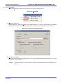
<4> Select the [Power target from the emulator] check box, and then select “5.0 V” for [Supply voltage].
Clicking the OK button displays the [Mode Pin at Connection] dialog box.
<R>
R20UT0599EJ0400 Rev. 4.00
2012.06.29
Figure 4-4. [Power Supply] Dialog Box
Page 27 of 168
Renesas Flash Programmer
CHAPTER 4 BASIC OPERATION (BASIC MODE) - RX -
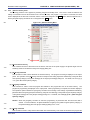
<5> Set the [Pin Outputs] check boxes and [Pin Setting (High)] check boxes. For R5F562TAA, set io2 of E1 to
High for the MD0 pin, and set io3 of E1 to Low for the MD1 pin.
Clicking the OK button displays the [Confirmation] dialog box.
Figure 4-5. [Mode Pin at Connection] Dialog Box
<R>
Remark: For the io0 to io5 pins of E1, refer to Figure B-3. E1 and E20 Pins - RX - in APPENDIX B.
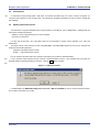
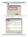
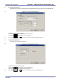
<6> Check that the board is connected, powered, and in Boot mode. Clicking the OK button displays the [Select
Emulator] dialog box.
<R>
<R>
Figure 4-6. [Confirmation] Dialog Box
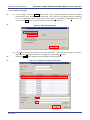
<7> The name and serial number of the detected Emulator are displayed. Select it. The serial number is printed
on the chassis.
Clicking the OK button establish connection with the device and displays the [Query Generic Device] dialog
box.
Figure 4-7. [Select Emulator] Dialog Box
R20UT0599EJ0400 Rev. 4.00
2012.06.29
Page 28 of 168
Renesas Flash Programmer
<R>
CHAPTER 4 BASIC OPERATION (BASIC MODE) - RX -
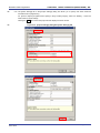
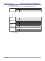
<8> A query for the target microcontroller is performed.
Clicking the OK button displays the [Frequency] dialog box.
Figure 4-8. [Query Generic Device] Dialog Box
<R>
<9> Enter “12.50” in the [Frequency:] box in the [Clock supply] area. The [Internal/External:] list box displays the
result of the query “External Resonator or Clock”. Select “8” from the [CKM:] list box in the [Multiplier for the
main clock or peripheral clock] area. Select “4” from the [CKP:] list box. The [Clock Mode:] list box displays
the result of the query “0”.
Clicking the Next > button displays the [Baudrate] dialog box.
<R>
R20UT0599EJ0400 Rev. 4.00
2012.06.29
Figure 4-9. [Frequency] Dialog Box
Page 29 of 168
Renesas Flash Programmer
<R>
<10> Clear the [Use Default] check box, and select “1562500” from the [Baud Rate (Recommended):] list box.
Clicking the Finish button displays the [Project Settings] dialog box.
Figure 4-10. [Baudrate] Dialog Box
<R>
<R>
CHAPTER 4 BASIC OPERATION (BASIC MODE) - RX -
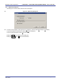
<11> The [Basic Settings] tab in the [Project Settings] dialog box allows you to check basic information about
programming. Clicking the [Other Settings] tab of the [Project Settings] dialog box displays the [Other
Settings] tab in the [Project Settings] dialog box.
<R>
Figure 4-11. [Project Settings] Dialog Box [Basic Settings] Tab
R20UT0599EJ0400 Rev. 4.00
2012.06.29
Page 30 of 168
Renesas Flash Programmer
<R>
CHAPTER 4 BASIC OPERATION (BASIC MODE) - RX -
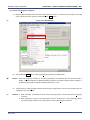
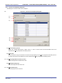
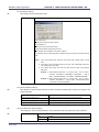
<12> The [Other Settings] tab in the [Project Settings] dialog box allows you to specify and check advanced
information about programming.
For [Connect Option] and [Disconnect Option] in the [Lock Bit] category, select “Do Nothing.” Leave the
initial values for other settings.
Clicking the OK button saves the project file and displays the main window.
<R>
Figure 4-12. [Project Settings] Dialog Box [Other Settings] Tab
R20UT0599EJ0400 Rev. 4.00
2012.06.29
Page 31 of 168
Renesas Flash Programmer
CHAPTER 4 BASIC OPERATION (BASIC MODE) - RX -
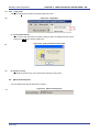
(5) Selection of program file
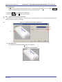
<1> Clicking the Browse… button in the User/Data area: of the program file area displays the [Open File] dialog
box.
<R>
R20UT0599EJ0400 Rev. 4.00
2012.06.29
Figure 4-13. Main Window
Page 32 of 168
Renesas Flash Programmer
<R>
CHAPTER 4 BASIC OPERATION (BASIC MODE) - RX -
<2> Select “sample.mot” in the [Open File] dialog box, and then click the Open button to open the main window.
<R>
R20UT0599EJ0400 Rev. 4.00
2012.06.29
Figure 4-14. [Open File] Dialog Box
Page 33 of 168
Renesas Flash Programmer
CHAPTER 4 BASIC OPERATION (BASIC MODE) - RX -
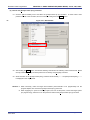
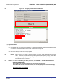
(6) Execute the [Program] command
<1> Click the [Microcontroller] menu and select the [Program] command. A check mark is then placed on the left
of the command, and the command is assigned to the Start button.
Figure 4-15. Main Window
<R>
<2> After clicking the Start button, execute the [Program] command for R5F562TAA.
<R>
Remark
When the [Program] command is executed, programming is performed after the block with data is
erased. To erase all blocks, set [All Erase Before Program] in the [Flash Program Options] category in
the [Other Settings] tab of the [Project Settings] dialog box to “True.”
<3>
When execution of the [Program] command ends normally, “Image written to device” and “Disconnected” are
displayed on the output panel.
<R>
Remarks 1. When necessary, connect the tool to be used to the target system, and then execute the [Program]
command.
2. When supplying VDD power to the target system, first turn off the power, connect the target system
(for programming), and then turn on the power and execute the [Program] command.
R20UT0599EJ0400 Rev. 4.00
2012.06.29
Page 34 of 168
Renesas Flash Programmer
<R>
CHAPTER 4 BASIC OPERATION (BASIC MODE) - RX -
Figure 4-16. [Program] Command Execution Results
(7) System shutdown
<1> Unless there are other target microcontrollers to be programmed, click the [File] menu and select the [Exit]
command to close RFP. All settings made so far will be saved to a project file.
<R>
<2> Remove the USB cable from the tool used.
<3> Disconnect the target cable from the target system.
<R>
Remark
When supplying VDD power to the target system, turn off the power before removing the target
cable. Furthermore, if [Auto Disconnect] in the [Flash Program Options] category in the [Other
Settings] tab of the [Project Settings] dialog box is set to “False,” remove the target system after
executing [Disconnect To Device].
<R>
Caution If an error occurs during the above procedure, see CHAPTER 12 TROUBLESHOOTING and
APPENDIX A MESSAGES.
Also see the user’s manual of the tool used and execute diagnostic tests.
If the above still does not resolve the problem, see the FAQ (at http://www.renesas.com/supp/),
or contact Renesas via the Renesas website:
http://www.renesas.com/contact/.
R20UT0599EJ0400 Rev. 4.00
2012.06.29
Page 35 of 168
Renesas Flash Programmer
CHAPTER 5 FUNCTION DETAILS (BASIC MODE) - RL78, 78K, 850 -
<R>
<R>
CHAPTER 5 FUNCTION DETAILS (BASIC MODE) - RL78, 78K, 850 -
This chapter describes function details of the commands, windows, and dialog boxes of the basic mode of RFP for the
RL78, 78K, and V850.
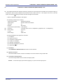
5.1
Introduction
Make sure that the RFP package is installed.
For how to install the RFP package, see CHAPTER 2
RFP
INSTALLATION. Before starting RFP, make sure that the debugger and utility are not running.
5.2
<R>
Starting up
On the taskbar, click the Start button, point to [All Programs], [Renesas Electronics Utilities], [Programming Tools],
[Renesas Flash Programmer Vx.xx], and then click [Renesas Flash Programmer Vx.xx]. The [Welcome!] dialog box will
open.
Follow the instructions that appear in the wizard.
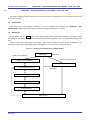
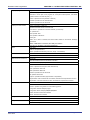
When setup is finished, the main window is displayed. The
[Frequency] and the [Power Supply] dialog boxes are skipped if it is not necessary to change the setting.
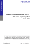
Figure 5-1. Dialog Boxes Displayed in the Startup Wizard
[Welcome!]
(See 5.2.1.)
Create a new workspace
Open a created workspace
[Create a new workspace]
(See 5.2.2.)
<R>
[Communication Interface]
(See 5.2.3.)
[Open File]
Open the workspace
used last time
(See 5.2.7.)
<R>
<R>
(See 5.2.8.)
[Frequency]
(See 5.2.4.)
<R>
[Power Supply]
(See 5.2.5.)
<R>
[Project Settings]
(See 5.2.6.)
Main window
(See 5.3.)
R20UT0599EJ0400 Rev. 4.00
2012.06.29
Page 36 of 168
Renesas Flash Programmer
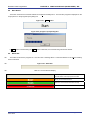
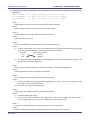
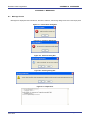
5.2.1
CHAPTER 5 FUNCTION DETAILS (BASIC MODE) - RL78, 78K, 850 -
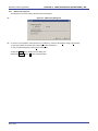
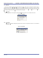
[Welcome!] dialog box
This dialog box is used to make a selection about a workspace.
Figure 5-2. [Welcome!] Dialog Box
<R>
<R> To create a new workspace, select [Create new workspace.], and also select [Basic Mode] or [Full Mode].
To open the workspace used last time, select [Open latest workspace.].
To open a created workspace, select [Open workspace.].
Clicking the Next button displays the next dialog box.
Clicking the Cancel or the X button terminates RFP.
R20UT0599EJ0400 Rev. 4.00
2012.06.29
Page 37 of 168
Renesas Flash Programmer
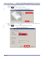
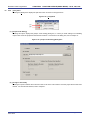
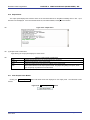
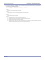
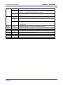
5.2.2
CHAPTER 5 FUNCTION DETAILS (BASIC MODE) - RL78, 78K, 850 -
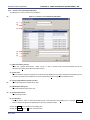
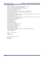
[Create new workspace] dialog box
This dialog box is used to create a new workspace.
Figure 5-3. [Create new workspace] Dialog Box
<R>
(1)
(2)
(3)
(4)
(5)
(6)
(1) [Microcontroller:] list box
Select “All”, ”Generic Boot Device”, “V850”, “RL78”, or “78K” to narrow down the microcontrollers that can be
selected in the [Using Target Microcontroller:] list box.
(2) [Filter:] box
Enter a character string that matches the character strings displayed in the [Using Target Microcontroller:] list box
to narrow down the microcontrollers that can be selected in the [Using Target Microcontroller:] list box.
<R> (3) [Using Target Microcontroller:] list box
Select the target microcontroller to be used.
(4) [Workspace Name:] box
Enter the workspace name in this box.
<R> (5) [Project Name:] box
Enter the project name in this box.
R20UT0599EJ0400 Rev. 4.00
2012.06.29
Page 38 of 168
Renesas Flash Programmer
CHAPTER 5 FUNCTION DETAILS (BASIC MODE) - RL78, 78K, 850 -
(6) [Folder:] box
Specify a folder in which to create the workspace file. Enter the path in the [Folder:] box, or click the Browse...
button to display the [Select Folder] dialog box, and then specify the folder.
Clicking the Next button displays the next dialog box.
Clicking the Cancel or the X button terminates RFP.
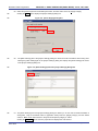
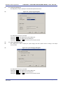
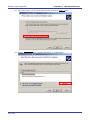
<R> 5.2.3
<R>
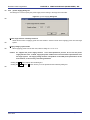
[Communication Interface] dialog box
This dialog box is used to select the tool used and the connection method used for communication between the
selected tool and the target microcontroller.
Figure 5-4. [Communication Interface] Dialog Box
<R>
(2)
(3)
(1)
(1) Tool image panel
An image of the tool selected in the [Tool:] list box is displayed.
Figure 5-5. Tool Image Panel
R20UT0599EJ0400 Rev. 4.00
2012.06.29
Page 39 of 168
Renesas Flash Programmer
CHAPTER 5 FUNCTION DETAILS (BASIC MODE) - RL78, 78K, 850 -
(2) [Tool:] list box
Select the tool to be used.
• E1
• E20
• MINICUBE2
• COMx
<R>
(3) [Interface:] list box
Select the method used for communication between the selected tool and the target microcontroller. For the
selectable methods, see the user's manual of the target microcontroller.
• UART-ch0 (when using the UART feature of 78K0, 78K0R, or V850)
• SIO-ch0 (when using V850E2)
• SIO-H/S (when using the SIO-H/S feature of V850ES or V850E1)
• UART-X1-OSC (when using the X1 clock of 78K0)
• UART-EXCLK (when using the EXCLK input clock of 78K0)
• UART-Int-OSC (when using the internal oscillation clock of 78K0)
Clicking the Next button displays the next dialog box.
Clicking the Cancel or the X button terminates RFP.
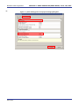
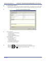
<R> 5.2.4
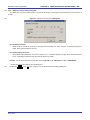
[Frequency] dialog box
This dialog box is used to specify the communication speed and the clock.
Figure 5-6. [Frequency] Dialog Box
<R>
(1)
(2)
R20UT0599EJ0400 Rev. 4.00
2012.06.29
Page 40 of 168
Renesas Flash Programmer
CHAPTER 5 FUNCTION DETAILS (BASIC MODE) - RL78, 78K, 850 -
(1) [Target Device Connection] area
<R>
This area is used to select the communication speed of the connection method.
Figure 5-7. [Target Device Connection] Area
<R>
<R>
[Interface:] box
The connection method between the tool used and the target microcontroller is displayed.
[Interface Speed:] list box
<R>
Select the communication speed for the connection method. For the selectable communication speeds, see
the user's manual of the target microcontroller.
• When UART-ch0, UART-X1-OSC, UART-EXCLK, or UART-Int-OSC is selected:
- 9,600 bps
- 19,200 bps
- 31,250 bps
- 38,400 bps
- 57,600 bps
- 76,800 bps
- 115,200 bps
- 125,000 bps
- 128,000 bps
- 153,600 bps
- 250,000 bps
- 500,000 bps
- 1,000,000 bps
• When SIO-ch0 or SIO-H/S is selected:
- 0.25 MHz
- 0.5 MHz
- 1 MHz
- 2 MHz
R20UT0599EJ0400 Rev. 4.00
2012.06.29
Page 41 of 168
Renesas Flash Programmer
CHAPTER 5 FUNCTION DETAILS (BASIC MODE) - RL78, 78K, 850 -
(2) [Supply Oscillator] area
This area is used to specify the clock to be supplied to the target device.
Figure 5-8. [Supply Oscillator] Area
[On Target] check box
Specify whether to supply a clock to the target microcontroller by using the clock generated in the target
system or the clock generated by the tool used. Select the check box to specify the clock generated in the
target system. Clear the check box to specify the clock generated by the tool used.
[Frequency:] text box
Select the oscillation frequency of the clock supplied to the target microcontroller. When using the clock
generated in the target system, input its oscillation frequency. When using the clock generated by the tool
used, input one of the frequencies below. For the selectable frequency, see the user's manual for the target
microcontroller.
• 4.00
• 8.00
• 16.00
[Multiply rate:] text box
Specify the multiplication ratio of the clock supplied to the target microcontroller. If the target microcontroller
includes the PLL circuit, input the multiplication ratio in accordance with the environment used. If the target
microcontroller does not include the PLL circuit, enter “1.0”. For the selectable multiplication ratio, see the
user's manual for the target microcontroller.
Clicking the Back button displays the previous dialog box.
Clicking the Next button displays the next dialog box.
Clicking the Cancel or the X button terminates RFP.
R20UT0599EJ0400 Rev. 4.00
2012.06.29
Page 42 of 168
Renesas Flash Programmer
<R>
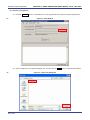
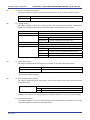
5.2.5
<R>
CHAPTER 5 FUNCTION DETAILS (BASIC MODE) - RL78, 78K, 850 -
[Power Supply] dialog box
This dialog box is used to specify the power supply and other options used for writing to the target microcontroller.
Figure 5-9. [Power Supply] Dialog Box
<R>
(1)
(2)
<R> (1) [Power supply from the emulator] area
This area is used to specify the power supply used for writing to the target microcontroller and the VDD value.
[Power target from the emulator] check box
<R>
Select this check box if supplying power from E1. Clear this check box if supplying power from the target
system.
<R>
[Supply voltage:] option button
When supplying power from the tool used, select a voltage of 3.3 V or 5.0 V.
Caution
E1 and MINICUBE2 support the power supply function. In the mass-production process, do not
use the power supply function of E1 or MINICUBE2. Instead, supply the power suitable for the
microcontroller specifications from the target system.
The supply voltage from E1 and
MINICUBE2 is dependent on the USB power performance of the host machine, so the accuracy
cannot be guaranteed.
R20UT0599EJ0400 Rev. 4.00
2012.06.29
Page 43 of 168
Renesas Flash Programmer
CHAPTER 5 FUNCTION DETAILS (BASIC MODE) - RL78, 78K, 850 -
<R> (2) [Additional Settings] area
This area is used to set power supply options.
[Wide Voltage Mode] check box
Select whether to use wide-voltage mode or full-speed mode. If this check box is selected, commands are
executed in wide-voltage mode. If this check box is cleared, commands are executed in full-speed mode. This
check box becomes available when a microcontroller that supports this feature is selected. For details about
wide-voltage mode and full-speed mode, see the user's manual of the target microcontroller.
Caution
When an HCUHEX file is read, the HCUHEX file is handled as master data. As a result, the
settings specified in the HCUHEX file are applied and this check box is unavailable.
<R>
[Input Voltage:] box
Input the voltage supplied to the target microcontroller.
Clicking the Back button displays the previous dialog box.
Clicking the Next button displays the next dialog box.
<R>
Clicking the Cancel or the X button terminates RFP.
R20UT0599EJ0400 Rev. 4.00
2012.06.29
Page 44 of 168
Renesas Flash Programmer
<R> 5.2.6
<R>
CHAPTER 5 FUNCTION DETAILS (BASIC MODE) - RL78, 78K, 850 -
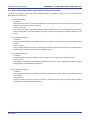
[Project Settings] dialog box
This dialog box is used to check and change the project settings. The [Basic Settings] tab and [Other Settings] tab are
provided, each of which allowing you to set a different type of setting categories.
Figure 5-10. [Project Settings] Dialog Box
<R>
<R>
For details about each item of the dialog box, see 5.4.3 (13) (d), [Project Settings] dialog box.
Clicking the Modify… button displays the [Communication Interface] dialog box.
Clicking the Complete button saves the project file and displays the main window.
Clicking the Cancel or the X button terminates RFP.
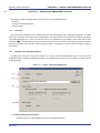
5.2.7
Open latest workspace
If you select [Open latest workspace.] in the [Welcome!] dialog box, the main window is displayed with the settings for
<R> the workspace used last time.
<R>
Figure 5-11. [Open latest workspace.]
R20UT0599EJ0400 Rev. 4.00
2012.06.29
Page 45 of 168
Renesas Flash Programmer
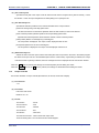
5.2.8
CHAPTER 5 FUNCTION DETAILS (BASIC MODE) - RL78, 78K, 850 -
Open workspace
If you select [Open workspace.] in the [Welcome!] dialog box, the [Open File] dialog box is displayed.
Figure 5-12. [Open workspace.]
<R>
Figure 5-13. [Open File] Dialog Box
Select a workspace file, and then click the Open button. The main window is displayed with the settings for the
specified workspace.
Clicking the Cancel or the X button closes the [Open File] dialog box and opens the [Welcome!] dialog box.
R20UT0599EJ0400 Rev. 4.00
2012.06.29
Page 46 of 168
Renesas Flash Programmer
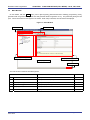
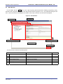
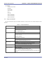
5.3
CHAPTER 5 FUNCTION DETAILS (BASIC MODE) - RL78, 78K, 850 -
Main Window
<R> On the taskbar, click the Start button, point to [All Programs], [Renesas Electronics Utilities], [Programming Tools],
[Renesas Flash Programmer Vx.xx], and then click [Renesas Flash Programmer Vx.xx]. The [Welcome!] dialog box will
open. Follow the instructions that appear in the wizard. When setup is finished, the main window is displayed.
Figure 5-14. Main Window
<R>
<1> Menu bar
<2> [Microcontroller] area
<3> [Program File] area
<4> [Command] area
<5> Start button
<6> Status bar
<7> Output panel
<8> [Clear Output Panel] button
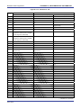
The main window consists of the following items:
Name
Description
See
<1>
Menu bar
Displays the selectable menus
5.4
<2>
[Microcontroller] area
Displays the selected target microcontroller
5.5
[Program File] area
Displays the selected program file
5.6
<4>
[Command] area
Displays the selected command
5.7
<5>
Start button
Executes the selected command
5.8
<6>
Status bar
Displays the command execution status in colors and text
5.9
<7>
Output panel
Displays in detail what is executed by the command
5.10
<8>
[Clear Output Panel] button
Clears the output panel display
5.11
<R> <3>
R20UT0599EJ0400 Rev. 4.00
2012.06.29
Page 47 of 168
Renesas Flash Programmer
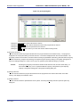
5.4
<R>
CHAPTER 5 FUNCTION DETAILS (BASIC MODE) - RL78, 78K, 850 -
Menu Bar
The menu bar consists of [File], [Tool], [Microcontroller], and [Help]. When a menu is selected, the pull-down menu is
displayed where the items can be selected. Some items may be disabled depending on the settings. When an HCUHEX
file has been selected, the HCUHEX file is handled as master data. As a result, the [Program], [Read], [Set Security], [Set
Option Bytes], and [Set OCD Security ID] commands become unavailable.
5.4.1
[File] menu
The following pull-down menu appears by selecting the [File] menu.
Figure 5-15. [File] Menu
(1)
(2)
(1) [Create a new workspace]
The [Create a new workspace] dialog box is displayed. Create a new workspace. Save the project file that has
been created. For the items in the dialog box, refer to 5.2.2.
Figure 5-16. [Create a new workspace] Dialog Box
<R>
<R>
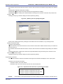
(2) [Open a workspace]
Selecting this option opens the [Open file] dialog box in which you can open a workspace created before. Save the
project file that has been created. For the items in the dialog box, refer to 5.2.8.
R20UT0599EJ0400 Rev. 4.00
2012.06.29
Page 48 of 168
Renesas Flash Programmer
CHAPTER 5 FUNCTION DETAILS (BASIC MODE) - RL78, 78K, 850 Figure 5-17. [Open File] Dialog Box
<R>
<R> (3) [Exit]
[Exit] terminates RFP. RFP can also be terminated by clicking the X button on the right end of the title bar in the
main window. When RFP is terminated, various settings are saved in the rfp.ini file. Save the project file that
has been created.
R20UT0599EJ0400 Rev. 4.00
2012.06.29
Page 49 of 168
Renesas Flash Programmer
<R> 5.4.2
CHAPTER 5 FUNCTION DETAILS (BASIC MODE) - RL78, 78K, 850 -
[Tool] menu
Selecting the [Tool] menu displays the pull-down menu as shown in the figure below.
Figure 5-18. [Tool] Menu
(1)
(2)
(1) [Unique Code Setting]
Selecting this option displays the [Unique Code Setting] dialog box, in which you make settings for imbedding
unique codes. Save the project file that has been created. For the items in the dialog box, refer to Chapter 11.
Figure 5-19. [Unique Code Setting] Dialog Box
(2) [Change to Full mode]
Selecting this option switches the mode from basic to full in the main window. Save the project file that has been
created. For the full mode features, refer to Chapter 7.
R20UT0599EJ0400 Rev. 4.00
2012.06.29
Page 50 of 168
Renesas Flash Programmer
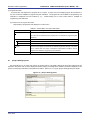
<R> 5.4.3
CHAPTER 5 FUNCTION DETAILS (BASIC MODE) - RL78, 78K, 850 -
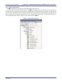
[Microcontroller] menu
The following pull-down menu appears by selecting the [Microcontroller] menu.
This menu includes commands mainly related to writing to the flash memory, such as setting up, erasing, and writing to
the flash memory, and verifying the written program. If you select a command, the check mark is displayed at the left of
the command, and the command is assigned to the Start button. The flash memory area subject to manipulation by each
<R> command is specified by using the [Operation mode] parameter under [Target] in the [Other settings] tag of the [Project
Settings] dialog box.
Figure 5-20. [Microcontroller] Menu
<R>
(1)
(2)
(3)
(4)
(5)
(6)
(7)
(8)
(9)
(10)
(11)
(12)
(13)
Caution
When an HCUHEX file has been selected, the HCUHEX file is handled as master data. As a result, the
[Program], [Read], [Set Security], [Set Option Bytes], and [Set OCD Security ID] commands become
unavailable.
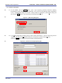
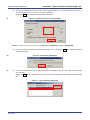
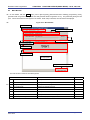
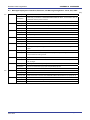
(1) [Blank Check] command
This command is used to check whether the flash memory is blank. If the flash memory has already been erased,
PASS is displayed. If the flash memory has not yet been erased, Error (E1002008) : Not Blank. is
displayed. If this error is displayed, erase the entire area of the flash memory in the target microcontroller before
starting programming.
(2) [Erase] command
This command is used to erase the flash memory. The progress of erasing is displayed on the output panel.
When erasing is complete, the result is displayed.
Whether to perform the [Blank Check] command before
executing this command depends on the setting of the [Blank Check before Erase] parameter under [Command
<R>
Options] in the [Other settings] tab of the [Project Settings] dialog box. If this command is executed for the flash
memory that has already been erased with [Blank Check before Erase] enabled, PASS. Erase skipped. is
displayed and erasure is not performed
R20UT0599EJ0400 Rev. 4.00
2012.06.29
Page 51 of 168
Renesas Flash Programmer
CHAPTER 5 FUNCTION DETAILS (BASIC MODE) - RL78, 78K, 850 -
(3) [Program] command
This command is used to write the program file selected in the program file area to the flash memory. The
progress of programming is displayed on the output panel. When programming is complete, the result is displayed.
The command options after the [Program] command has finished executing depend on the settings of the [Verify
<R>
after Program], [Security after Program], and [Checksum after Program] parameters under [Command Options] in
the [Other Settings] tab of the [Project Settings] dialog box. For details, see 5.4.3 (13) (d) <9> [Command
Options] category.
(4) [Verify] command
This command is used to verify that the data written to the flash memory is the same as the data in the program file
selected in the program file area. The progress of verifying is displayed on the output panel. When verifying is
complete, the result is displayed.
(5) [Read] command
This command is used to read data on the flash memory and save it as a file. When this command is executed,
the [Save As] dialog box is displayed. Enter any file name in the [File name:] box, select the folder in which to store
the file, and then save the program data that has been read. Select the file format from “Intel Hex files(*.hex)” or
“Motorola S record files(*.rec;*.s)” in the [Save as type:] list box.
Figure 5-21. [Save As] Dialog Box
Clicking the Save button saves the program data as a file and closes the dialog box.
Clicking the Cancel or the X button closes the dialog box without saving the program data as a file.
(6) [Set Security] command
This command is used to specify the security settings for the target microcontroller. When this command is
<R>
executed, the settings specified in the [Flash Options] category in the [Other Settings] tab of the [Project Settings]
dialog box will be applied to the target microcontroller. For details about the security settings, see 5.4.3 (13) (d)
<7> [Flash Options] category.
R20UT0599EJ0400 Rev. 4.00
2012.06.29
Page 52 of 168
Renesas Flash Programmer
CHAPTER 5 FUNCTION DETAILS (BASIC MODE) - RL78, 78K, 850 -
(7) [Checksum] command
This command is used to read the checksum calculated in the target microcontroller and displays it in the output
panel.
<R>
Remark
The checksum read by this command differs from the one displayed in the [Program File] category in the
[Other Settings] tab of the [Project Settings] dialog box. For details about the [Program File] category,
see 5.4.3 (13) (d) <7> [Program File] category.
The checksum is calculated as follows:
• When using RL78, 78K, V850E1, or V850ES:
Method: Subtraction (16-bit arithmetic)
<R>
Range:
Area specified in the [Command Options] category in the [Other Settings] tab of the [Project Settings]
dialog box
Figure 5-22. Output Panel After [Checksum] Command Execution (When Using RL78, 78K, V850E1, or V850ES)
Checksum Code flash: 0x2A8E
Checksum PASS
Remark
With the 16-bit arithmetic (subtraction) mode, the lower 4 digits of the result from which a value is
subtracted from 00h in 1-byte units are displayed.
• When using V850E2:
Method: 32-bit CRC
<R>
Range:
Area specified by the [Operation mode] parameter under [Command Options] in the [Other Settings]
tab of the [Project Settings] dialog box
Figure 5-23. Output Panel After [Checksum] Command Execution (When Using V850E2)
Checksum Code flash: 0xD1CA2956
Checksum PASS
Remark
With the 32-bit CRC mode, the 8-digit result of CRC32 function calculation is displayed. For details
about the arithmetic specifications, see Figure B-2. 32-bit CRC Calculation Specifications.
R20UT0599EJ0400 Rev. 4.00
2012.06.29
Page 53 of 168
Renesas Flash Programmer
CHAPTER 5 FUNCTION DETAILS (BASIC MODE) - RL78, 78K, 850 -
(8) [Autoprocedure (E.P)] command
This command is used to execute the [Erase] and [Program] commands in succession for the flash memory. The
progress of execution is displayed on the output panel. When execution is complete, the result is displayed. The
command options after the [Autoprocedure (E.P)] command has finished executing depend on the settings of the
[Blank Check before Erase], [Verify after Program], [Security after Program], and [Checksum after Program]
<R>
parameters under [Command Options] in the [Other Settings] tab of the [Project Settings] dialog box. For details
about these check boxes, see 5.4.3 (13) (d) <9> [Command Options] category.
Figure 5-24. Output Panel After [Autoprocedure (E.P)] Command Execution
========== (Connect) ==========
------ Start(Autoprocedure(E.P)) -----Blank check Code flash: Not blank, Erase need.
Erasing...
Erase Chip : PASS
Program Code flash:
10%
20%
30%
40%
50%
60%
70%
80%
90%
100%
PASS
Autoprocedure(E.P) PASS
------ End(Autoprocedure(E.P)) -----========== (Disconnect) ==========
(9) [Set Option bytes] command
This command is used to specify the settings for the target microcontroller's option byte. When this command is
<R>
executed, the settings specified by the [OPBTn] parameter in the [Flash Options] category in the [Other Settings]
tab of the [Project Settings] dialog box are applied to the target microcontroller. For details about the option byte
settings, see 5.4.3 (13) (d) <7> [Flash Options] category.
(10) [Set OCD Security ID] command
This command is used to specify the settings for the target microcontroller's on-chip debug security ID. When this
<R>
command is executed, the settings specified by the [OCD Security ID] parameter in the [Flash Options] category in
the [Other Settings] tab of the [Project Settings] dialog box are applied to the target microcontroller. For details
about the on-chip debug security ID settings, see 5.4.3 (13) (d) <7> [Flash Options] category.
(11) [Signature Read] command
This command is used to read the target microcontroller's product information, such as the microcontroller name
and flash memory information. The read result is displayed in the output panel.
R20UT0599EJ0400 Rev. 4.00
2012.06.29
Page 54 of 168
Renesas Flash Programmer
CHAPTER 5 FUNCTION DETAILS (BASIC MODE) - RL78, 78K, 850 -
(12) [Get Flash options] command
This command is used to read the settings for the flash options for the target microcontroller and displays the result
<R>
under the [Flash Options] category in the [Other Settings] tab of the [Project Settings] dialog box. When this
command is enabled, execute this command before the [Set Security] command, [Set Option bytes] command, or
[Set OCD Security ID] command; the settings for the flash option settings can thus be checked. For details about
the flash option settings, see 5.4.3 (13) (d) <7> [Flash Options] category.
Caution When an HCUHEX file is read, the HCUHEX file is handled as master data. As a result, the flash
options specified in the microcontroller can be checked by executing the [Get Flash options]
command but the settings cannot be applied. Click the OK button to close the dialog box.
<R>
Figure 5-25. Items Read by the [Get Flash options] Command
R20UT0599EJ0400 Rev. 4.00
2012.06.29
Page 55 of 168
Renesas Flash Programmer
CHAPTER 5 FUNCTION DETAILS (BASIC MODE) - RL78, 78K, 850 -
<R> (13) [Set Project]
Selecting [Set Project] displays the [Project Settings] dialog box, where you can check and change the project
settings. The dialog box has two tabs: [Basic Settings] and [Other Settings]. Different categories of settings are
displayed depending on the tab you select. Clicking the [Modify…] button of the [Basic Settings] tab opens the
wizard-type dialog box [Communication Interface] (see Figure 5-26), which guides you through the process of
changing the settings. The [Frequency] and the [Power Supply] dialog boxes are skipped if the settings do not
need to be changed.
<R>
Figure 5-26. Flow of Setting Modification with the [Modify…] Button
[Communication interface]
[Frequency]
[Power supply]
[Project settings]
<R>
<R>
(a) [Communication Interface] dialog box
This dialog box is used to select the tool used and the interface used for communication between the selected
tool and the target microcontroller.
Figure 5-27. [Communication Interface] Dialog Box
<R>
For details about each item, see 5.2.3.
<R>
Clicking the Next button displays the next dialog box.
Clicking the Cancel or the X button returns you to the main window.
R20UT0599EJ0400 Rev. 4.00
2012.06.29
Page 56 of 168
Renesas Flash Programmer
<R>
CHAPTER 5 FUNCTION DETAILS (BASIC MODE) - RL78, 78K, 850 -
(b) [Frequency] dialog box
This dialog box is used to specify the communication speed and the clock.
Figure 5-28. [Frequency] Dialog Box
<R>
For details about each item, see 5.2.4.
Clicking the Back button displays the previous dialog box.
Clicking the Next button displays the next dialog box.
Clicking the Cancel or the X button returns you to the main window.
<R>
<R>
(c) [Power Supply] dialog box
This dialog box is used to specify the power supply and other options used for writing to the target
microcontroller.
Figure 5-29. [Power Supply] Dialog Box
<R>
For details about each item, see 5.2.5.
Clicking the Back button displays the previous dialog box.
Clicking the Next button displays the next dialog box.
Clicking the Cancel or the X button returns you to the main window.
R20UT0599EJ0400 Rev. 4.00
2012.06.29
Page 57 of 168
Renesas Flash Programmer
<R>
<R>
CHAPTER 5 FUNCTION DETAILS (BASIC MODE) - RL78, 78K, 850 -
(d) [Project Settings] dialog box
This dialog box is used to check and change the project settings. The dialog box has two tabs: [Basic
Settings] and [Other Settings]. Different categories of settings are displayed depending on the tab you select.
Figure 5-30. [Project Settings] Dialog Box
<R>
<R>
[Basic Settings] tab
<1> [Device Information File] category
<2> [Target] category
<3> [Using Tool] category
<4> [Power Supply Options] category
[Other Settings] tab
<5> [Program File] category
<6> [Target] category
<7> [Flash Options] category
<8> [Target Microcontroller] category
<9> [Command Options] category
<R>
Clicking the Modify.. button displays the [Communication Interface] dialog box.
Clicking the Complete button saves the project file and returns you to the main window.
Clicking the Cancel or the X button returns you to the main window.
R20UT0599EJ0400 Rev. 4.00
2012.06.29
Page 58 of 168
Renesas Flash Programmer
<R>
CHAPTER 5 FUNCTION DETAILS (BASIC MODE) - RL78, 78K, 850 -
<1> [Device Information File] category
This category displays information about device information files such as the file name and file version.
<R>
File name
Displays the device information file name.
File version
Displays the version of the device information file.
<2> [Target] category
This category displays or allows you to select specifics, such as the connection method, communication
transfer rate, and supplied clock, about the interface between the tool and the microcontroller.
Interface
Displays the connection method.
Communication transfer rate
Displays the communication speed.
Supplied oscillator
Displays the type of clock source supplied to the microcontroller.
The clock is supplied from the target system.
Programmer
The clock is supplied from the tool used.
Frequency [MHz]
Displays the frequency of the clock supplied to the microcontroller.
Multiply rate
Displays the multiply rate of the clock supplied to the microcontroller.
Supply power
Displays the voltage supplied to the microcontroller.
Remark
<R>
Target
Target
The voltage is supplied from the target system.
3.3 V
A voltage of 3.3 V is supplied from the tool used.
5.0 V
A voltage of 5.0 V is supplied from the tool used.
x.xx V
The voltage is supplied from the target system.
[Power Supply] is displayed when a power-related setting is made.
<3> [Using Tool] category
This category displays information about the tool used such as the name and firmware version.
Tool name
Displays the name of the tool used.
Firmware version
Displays the version of the MINICUBE2 firmware.
Remark
The [Firmware version] view is updated whenever a command on the target
microcontroller finishes executing.
<R>
<4> [Power Supply Options] category
This category displays the power supply options, such as wide voltage mode, of the command executed
on the flash memory.
Wide voltage mode
Select whether to write in wide voltage mode.
Valid
Data is written in wide voltage mode.
Invalid
Data is not written in wide voltage mode.
Remark Some items in this category might not be displayed depending on the type of microcontrollers.
<5> [Program File] category
This category displays or is used to select information about the specified program file such as the file
name, date updated, and checksum calculation method.
R20UT0599EJ0400 Rev. 4.00
2012.06.29
Page 59 of 168
Renesas Flash Programmer
CHAPTER 5 FUNCTION DETAILS (BASIC MODE) - RL78, 78K, 850 -
File name
Displays the selected program file name.
Updated date
Displays the date that the program file selected by [File name] was last modified.
Type
Displays the type of the program file selected in [File name]. HCUHEX is
displayed when an HCUHEX file is read. HEX is displayed when a HEX file
without option data is read.
Check sum type
Select the checksum calculation method for the program file selected by [File
name].
Range
Arithmetic check
sum (16-bit)
The checksum calculated using 16-bit subtraction.
CRC sum (32-bit)
The checksum calculated using 32-bit CRC.
Select the area from which to calculate the checksum.
Range of the
Program file
The area to which the program file selected by [File name]
is assigned is subject to checksum calculation.
Range of target
microcontroller
All flash memory area built into the microcontroller
specified by the project is subject to checksum calculation.
User optional range
(Code Flash)
An area from [Start address of Code Flash] to [End
address of Code Flash] is subject to checksum calculation.
User optional range
(Data Flash)
An area from [Start address of Data Flash] to [End address
of Data Flash] is subject to checksum calculation.
User optional range
(Code Flash + Data
Flash)
The area specified by [Start address of Code Flash] and
[End address of Code Flash], and the area specified by
[Start address of Data Flash] and [End address of Data
Flash] are subject to checksum calculation.
Start address of
Code Flash
Enter the start address of the code flash memory for which to calculate the
checksum.
End address of
Code Flash
Enter the end address of the code flash memory for which to calculate the
checksum.
Check sum of
Code Flash
Displays the results of checksum calculation using the method selected by [Check
sum type].
Start address of
Data Flash
Enter the start address of the data flash memory for which to calculate the
checksum.
End address of
Data Flash
Enter the end address of the data flash memory for which to calculate the
checksum.
Check sum of
Data Flash
Displays the results of checksum calculation using the method selected by [Check
sum type].
Remarks 1. The [Updated date] view is refreshed whenever a file name is specified for [File name].
2. The [Check sum of Code Flash] and [Check sum of Data Flash] views are refreshed
whenever a checksum calculation mode is specified for [Check sum type].
3. If "Range of the Program file" is selected for [Range], the corresponding addresses are
specified for [Start address of Code Flash] and [End address of Code Flash], and [Start
address of Data Flash] and [End address of Data Flash], and further input is disabled.
4. When the checksum is calculated, areas to which data is not written are filled in with 0xff.
5. Some items in this category might not be displayed for some microcontrollers.
6. With the 16-bit arithmetic (subtraction) mode, the lower 4 digits of the result from which a
value is subtracted from 00h in 1-byte units are displayed. With the 32-bit CRC mode, the
8-digit result of CRC32 function calculation is displayed. For details about the arithmetic
specifications, see Figure B-2. 32-bit CRC Calculation Specifications.
R20UT0599EJ0400 Rev. 4.00
2012.06.29
Page 60 of 168
Renesas Flash Programmer
<R>
CHAPTER 5 FUNCTION DETAILS (BASIC MODE) - RL78, 78K, 850 -
<6> [Target] category
This category is used to select the operation mode and other details about the interface between the tool
and the microcontroller.
Operation mode
Select the unit in which the flash memory is accessed.
Chip
The flash memory is accessed in chip units.
Block (Code Flash)
The code flash memory is accessed in
block units.
Block (Data Flash)
The data flash memory is accessed in block
units.
Block (Code Flash +
Data Flash)
The flash memory is accessed in block
units.
Start block number of Code
Flash
Select the starting block when accessing code flash memory in block
units.
End block number of Code
Flash
Select the ending block when accessing code flash memory in block
units.
Start block number of Data
Flash
Select the starting block when accessing data flash memory in block
units.
End block number of Data
Flash
Select the ending block when accessing data flash memory in block
units.
Supplied Power
Displays the voltage supplied to the target microcontroller.
Note
When an HCUHEX file is read, the HCUHEX file is handled as master data. As a result, [Chip]
is selected and this setting cannot be changed.
Remarks 1. [Start block number of Code Flash] and [End block number of Code Flash] are displayed
only if “Block (Code Flash)” or “Block (Code Flash + Data Flash)” is selected under
[Operation mode].
2. [Start block number of Data Flash] and [End block number of Data Flash] are displayed
only if “Block (Data Flash)” or “Block (Code Flash + Data Flash)” is selected under
[Operation mode].
R20UT0599EJ0400 Rev. 4.00
2012.06.29
Page 61 of 168
Renesas Flash Programmer
<R>
CHAPTER 5 FUNCTION DETAILS (BASIC MODE) - RL78, 78K, 850 -
<7> [Flash Options] category
This category is used to disable execution of commands on the flash memory (by selecting settings such
as Disable Chip Erase, Disable Block Erase, or Disable Program) and display microcontroller information
such as the end of boot block number, reset vector address, and start of flash shield block number.
Disable Chip Erase
Disable Block Erase
Disable Program
Disable Read
Disable boot block
cluster reprogramming
Used to disable execution of the chip erase command on the flash
memory.
Valid
Execution of the chip erase command is disabled.
Invalid
Execution of the chip erase command is enabled.
Used to disable execution of the block erase command on the flash
memory.
Valid
Execution of the block erase command is disabled.
Invalid
Execution of the block erase command is enabled.
Used to disable execution of the write command on the flash memory.
Valid
Execution of the write command is disabled.
Invalid
Execution of the write command is enabled.
Used to disable execution of the read command on the flash memory.
Valid
Execution of the read command is disabled.
Invalid
Execution of the read command is enabled.
Used to disable writing to the boot area.
Valid
Writing to the boot area is disabled.
Invalid
Writing to the boot area is enabled.
End of boot block
number
Displays the end of the boot area.
Reset vector address
Displays the reset vector address of the microcontroller.
Start of flash shield
block number
Select the starting block of the flash shield window.
End of flash shield
block number
Select the ending block of the flash shield window.
OCD Security ID
Enter the on-chip debug security ID.
OPBTn
Select the option byte.
Note
When an HCUHEX file is read, the HCUHEX file is handled as master data. As a result, the
settings specified in the HCUHEX file are applied and the settings in this category cannot be
changed.
Remark
<R>
Some items in this category might not be displayed for some microcontrollers.
<8> [Target Microcontroller] category
This category displays information about the microcontroller such as the target microcontroller name and
firmware version.
Target microcontroller name
Displays the microcontroller name.
Firmware version
Displays the version of the microcontroller firmware.
Remark
The [Target microcontroller name] and [Firmware version] views are refreshed whenever a
command finishes executing on the target microcontroller.
R20UT0599EJ0400 Rev. 4.00
2012.06.29
Page 62 of 168
Renesas Flash Programmer
<R>
CHAPTER 5 FUNCTION DETAILS (BASIC MODE) - RL78, 78K, 850 -
<9> [Command Options] category
This category is used to specify options for commands executed on the flash memory such as Blank
Check before Erase, Verify after Program, and Security after Program.
Blank Check before
Note
Erase
Verify after Program
Security after
Note
Program
Check Sum after
Program
Set Option Bytes after
Note
Program
Set OCD Security ID
Note
after Program
R20UT0599EJ0400 Rev. 4.00
2012.06.29
Select whether or not to check the status of the flash memory (whether or
not data has been written) before erasing data written to the flash
memory.
Valid
Data is erased after checking the status of the flash memory.
Invalid
Data is erased without checking the status of the flash memory.
Select whether or not to verify that the data written to the flash memory
matches the data in the file specified by the [File name] parameter under
[Program File] after writing to the flash memory is complete.
Valid
Data match is verified after writing is complete.
Invalid
Data match is not verified after writing is complete.
Select whether or not to apply the security settings specified in the [Flash
Options] category such as Blank Check before Erase, Verify after
Program, and Security after Program, after the writing to the flash
memory is complete.
Valid
The security settings are applied after writing is complete.
Invalid
The security settings are not applied after writing is complete.
Select whether or not to read the checksum of the data written to the
flash memory after writing is complete.
Valid
The checksum is read after writing is complete.
Invalid
The checksum is not read after writing is complete.
Select whether or not to apply the option byte settings specified in the
[Flash Options] category after writing to the flash memory is complete.
Valid
The option byte settings are applied after writing is complete.
Invalid
The option byte settings are not applied after writing is
complete.
Select whether or not to apply the on-chip debug security ID specified in
the [Flash Options] category after writing to the flash memory is complete.
Valid
The on-chip debug security ID is applied after writing is
complete.
Invalid
The on-chip debug security ID is not applied after writing is
complete.
Page 63 of 168
Renesas Flash Programmer
CHAPTER 5 FUNCTION DETAILS (BASIC MODE) - RL78, 78K, 850 -
Reset Pin as Low
Select whether or not to set the reset pin to the low level when
disconnecting the device.
Valid
The reset pin is set to low level.
Invalid The reset pin is set to high impedance.
Program file size monitor
function
Note
Halts execution of programming command if the program file size
exceeds the programmable range.
Valid
If the address range of the downloaded program file exceeds
the range specified for [Operation mode] in the [Target]
category and the [Program], [Verify], or [Autoprocedure(E.P)]
command is executed, the error message “Error (E1002018):
HEX file exceeds target device flash range.” is displayed on the
output panel and command execution is halted.
Invalid
The message “Truncate the HEX File.” is displayed on the
output panel and command execution continues.
When an HCUHEX file is read, the HCUHEX file is handled as master data. As a result, the
settings of [Blank Check before Erase], [Security after Program], [Set Option Bytes after
Program], and [Set OCD Security ID after Program] cannot be changed.
Remarks 1. The results of executing the command in accordance with the specified options are shown
in the output panel.
2. Some items in this category might not be displayed depending on the type of
microcontrollers.
R20UT0599EJ0400 Rev. 4.00
2012.06.29
Page 64 of 168
Renesas Flash Programmer
<R> 5.4.4
CHAPTER 5 FUNCTION DETAILS (BASIC MODE) - RL78, 78K, 850 -
[Help] menu
Clicking the [Help] menu displays the following pull-down menu.
Figure 5-31. [Help] Menu
<R>
(1)
(2)
(1) [Version Information]
This is used to open the Version Information dialog box below and display the RFP version.
Clicking the OK button closes this dialog box.
Figure 5-32. Version Information Dialog Box
<R>
(2) [Import License]
For details of this menu item, see the manual accompanying this product.
5.5
[Microcontroller] Area
This area displays the selected target microcontroller.
Figure 5-33. [Microcontroller] Area
R20UT0599EJ0400 Rev. 4.00
2012.06.29
Page 65 of 168
Renesas Flash Programmer
5.6
CHAPTER 5 FUNCTION DETAILS (BASIC MODE) - RL78, 78K, 850 -
[Program File] Area
This area displays the selected program file. Clicking the Browse... button opens the [Open File] dialog box. Move to
a desired folder and select a program file (*.hex;*.mot;*.s*;*.rec).
Figure 5-34. [Program File] Area
Figure 5-35. [Open File] Dialog Box
5.7
[Command] Area
The command area displays the command selected on the [Microcontroller] menu.
Figure 5-36. Command Area
R20UT0599EJ0400 Rev. 4.00
2012.06.29
Page 66 of 168
Renesas Flash Programmer
5.8
CHAPTER 5 FUNCTION DETAILS (BASIC MODE) - RL78, 78K, 850 -
Start Button
Clicking the Start button executes the command selected on the [Microcontroller] menu. The execution progress is
displayed on the output panel or in the [Progress report] dialog box.
Figure 5-37. Start Button
Figure 5-38. [Progress report] Dialog Box
5.9
Status Bar
The status bar shows the progress as a color or with a message when a command selected on the [Microcontroller]
menu is executed.
Figure 5-39. Status Bar
Table 5-1. Status Bar Displays
After startup or when the [Clear
Output Panel] button is clicked
A command is being executed.
The command finished executing
normally
The command terminated
abnormally.
R20UT0599EJ0400 Rev. 4.00
2012.06.29
Page 67 of 168
Renesas Flash Programmer
CHAPTER 5 FUNCTION DETAILS (BASIC MODE) - RL78, 78K, 850 -
5.10 Output Panel
The output panel displays the execution status of the command selected on the [Microcontroller] menu in text. Up to
500 lines can be displayed. If the text exceeds 500 lines, lines will be deleted, starting from the first line.
Figure 5-40. Output Panel
<R> (a) Output Panel Context Menu
Right-clicking the output panel displays a context menu.
Table 5-2 Output Panel Context Menu
Copy
Copies the text selected on the output panel to the clip board.
Select All
Selects the entire text on the output panel.
Clear
Clears the entire text and the status bar display of the output panel.
Save
Saves the entire text on the output panel to a file. The [Open File] dialog box opens, where
you can specify any filename for the file saved.
5.11 Clear Output Panel Button
Clicking the Clear Output Panel button will delete all the text displayed on the output panel. The status bar is also
cleared.
Figure 5-41. Clear Output Panel Button
R20UT0599EJ0400 Rev. 4.00
2012.06.29
Page 68 of 168
Renesas Flash Programmer
CHAPTER 6 FUNCTION DETAILS (BASIC MODE) - RX -
<R>
<R>
CHAPTER 6 FUNCTION DETAILS (BASIC MODE) - RX -
This chapter describes function details of the commands, windows, and dialog boxes of the basic mode of RFP for RX.
6.1
Introduction
Make sure that the RFP package is installed.
For how to install the RFP package, see CHAPTER 2
RFP
INSTALLATION. Before starting RFP, make sure that the debugger and utility are not running.
6.2
<R>
Starting up
On the taskbar, click the Start button, point to [All Programs], [Renesas Electronics Utilities], [Programming Tools],
[Renesas Flash Programmer Vx.xx], and then click [Renesas Flash Programmer Vx.xx]. The [Welcome!] dialog box will
open.
Follow the instructions that appear in the wizard. When setup is finished, the main window is displayed. The [Power
Supply] and the [Mode Pin at Connection] dialog boxes are skipped depending on the selected connection method.
<R>
Figure 6-1. Dialog Boxes Displayed in the Startup Wizard
[Welcome!]
Create a new workspace
(See 6.2.1)
Open a created
workspace
[Create a new workspace]
(See 6.2.2)
[Open workspace]
[Communication Interface]
(See 6.2.11)
(See 6.2.3)
[Power Supply]
(See 6.2.4)
Open latest workspace
[Mode Pin at Connection]
(See 6.2.10)
(See 6.2.5)
[Connection and Query]
(See 6.2.6)
[Frequency]
(See 6.2.7)
[Baud Rate]
(See 6.2.8)
[Project Settings]
(See 6.2.9)
Main window
(See 6.3)
R20UT0599EJ0400 Rev. 4.00
2012.06.29
Page 69 of 168
Renesas Flash Programmer
6.2.1
CHAPTER 6 FUNCTION DETAILS (BASIC MODE) - RX -
[Welcome!] dialog box
This dialog box is used to make a selection about a workspace.
Figure 6-2. [Welcome!] Dialog Box
<R>
<R> To create a new workspace, select [Create new workspace.], and then select [Basic mode] or [Full mode].
To open the workspace used last time, select [Open latest workspace.].
To open a created workspace, select [Open workspace.].
Clicking the Next button displays the next dialog box.
Clicking the Cancel or the X button terminates RFP.
R20UT0599EJ0400 Rev. 4.00
2012.06.29
Page 70 of 168
Renesas Flash Programmer
6.2.2
CHAPTER 6 FUNCTION DETAILS (BASIC MODE) - RX -
[Create a new workspace] dialog box
This dialog box is used to create a new workspace.
Figure 6-3. [Create a new workspace] Dialog Box
<R>
(1)
(2)
(3)
(4)
(5)
(6)
(1) [Microcontroller:] list box
Select “All”, “Generic Boot Device”, “V850”, “RL78”, or “78K” to narrow down the microcontrollers that can be
selected in the [Using Target Microcontroller:] list box.
(2) [Filter:] box
Enter a character string that matches the character strings displayed in the [Using Target Microcontroller:] list box
to narrow down the microcontrollers that can be selected in the [Using Target Microcontroller:] list box.
(3) [Using Target Microcontroller:] list box
<R>
Select the target microcontroller to be used.
(4) [Workspace Name:] box
Enter the workspace name in this box.
<R> (5) [Project Name:] box
Enter the project name.
(6) [Folder:] box
Specify a folder in which to create the workspace file. Enter the path in the [Folder:] box, or click the Browse...
button to display the [Select Folder] dialog box, and then specify the folder.
Clicking the Next button displays the next dialog box.
Clicking the Cancel or the X button terminates RFP.
R20UT0599EJ0400 Rev. 4.00
2012.06.29
Page 71 of 168
Renesas Flash Programmer
<R> 6.2.3
CHAPTER 6 FUNCTION DETAILS (BASIC MODE) - RX -
[Communication Interface] dialog box
This dialog box is used to select the tool used and display the connection method between the selected tool and the
target microcontroller.
Figure 6-4. [Communication Interface] Dialog Box
<R>
(2)
(3)
(1)
(1) Tool image panel
An image of the tool selected in the [Select Tool:] list box is displayed.
Figure 6-5. Tool Image Panel
(2) [Tool:] list box
Select the tool to be used.
• E1
• E20
• USB Direct
<R>
• COMx
(3) [Interface:] list box
The connection method between the selected tool and the target microcontroller is displayed.
• Boot mode
Clicking the Next > button displays the next dialog box.
Clicking the Cancel or the X button terminates RFP.
R20UT0599EJ0400 Rev. 4.00
2012.06.29
Page 72 of 168
Renesas Flash Programmer
<R> 6.2.4
CHAPTER 6 FUNCTION DETAILS (BASIC MODE) - RX -
[Power Supply] dialog box
This dialog box is used to specify the power supply used for writing to the target microcontroller.
Figure 6-6. [Power Supply] Dialog Box
<R>
[Power target from the emulator] check box
Select this check box if supplying power from the emulator. Clear this check box if supplying power from the target
<R>
system.
[Supply voltage:] option button
<R>
When supplying power from the tool used, select a voltage of 3.3 V or 5.0 V.
Caution
E1 supports the power supply function. In the mass-production process, do not use the power
supply function of E1. Instead, supply the power suitable for the microcontroller specifications from
the target system. The supply voltage from E1 is dependent on the USB power performance of the
host machine, so the accuracy cannot be guaranteed.
Clicking the OK button displays the next dialog box.
Clicking the Cancel or the X button returns you to the [Communication Interface] dialog box.
<R>
R20UT0599EJ0400 Rev. 4.00
2012.06.29
Page 73 of 168
Renesas Flash Programmer
<R> 6.2.5
CHAPTER 6 FUNCTION DETAILS (BASIC MODE) - RX -
[Mode Pin at Connection] dialog box
This dialog box is used to select the pin to control the mode pin of the target microcontroller from io0 to io5 pins of
E1/E20.
Figure 6-7. [Mode Pin at Connection] Dialog Box
<R>
[Pin Outputs] check box
Select the pin to control the mode pin of the target microcontroller from io0 to io5 pins. A selected check box is
output, and a cleared check box is input.
[Pin Setting (High)] check box
Set the level of the selected io0 to io5 pins to High or Low. A selected check box is High, and a cleared check box
is Low. This setting is effective only when the I/O direction is Output.
Remark
For the io0 to io5 pins of E1 and E20, refer to Figure B-3. E1 and E20 Pins - RX - in APPENDIX B.
Clicking the OK button displays the next dialog box.
<R>
Clicking the Cancel or the X button returns you to the [Communication Interface] dialog box.
R20UT0599EJ0400 Rev. 4.00
2012.06.29
Page 74 of 168
Renesas Flash Programmer
6.2.6
CHAPTER 6 FUNCTION DETAILS (BASIC MODE) - RX -
[Connection and Query] dialog box
This dialog box is used to perform connection and a query of the target microcontroller and create a device information
file.
<R>
Caution
The connection is maintained after querying the device until the disconnection processing is executed.
(1) Confirm before connecting to the target microcontroller.
Figure 6-8. [Confirmation] Dialog Box
<R>
Clicking the OK button displays the next dialog box.
<R>
Clicking the Cancel or the X button returns you to the [Communication Interface] dialog box.
(2) When E1 or E20 is selected, the [Select Emulator] dialog box is displayed. The name and serial number of the
detected USB device are displayed. Select it.
Figure 6-9. [Select Emulator] Dialog Box
Clicking the OK button displays the next dialog box.
<R> Clicking the Cancel or the X button returns you to the [Communication Interface] dialog box.
Remark
This dialog box is displayed only when RFP starts up for the first time. It won’t be displayed for the second
time and on. After a restart of RFP, it is displayed only for the first time and not for the second time and on.
R20UT0599EJ0400 Rev. 4.00
2012.06.29
Page 75 of 168
Renesas Flash Programmer
CHAPTER 6 FUNCTION DETAILS (BASIC MODE) - RX -
<R> (3) When USB Direct is selected, the [Select USB Device] dialog box is displayed. The detected USB port number is
displayed. Select it.
<R>
Figure 6-10. [Select USB Device] Dialog Box
Clicking the OK button displays the next dialog box.
<R> Clicking the Cancel or the X button returns you to the [Communication Interface] dialog box.
Remark
This dialog box is displayed only when RFP starts up for the first time. It won’t be displayed for the second
time and on. After a restart of RFP, it is displayed only for the first time and not for the second time and on.
(4) A query for the target microcontroller is performed.
Figure 6-11. [Query Generic Device] Dialog Box
Clicking the OK button displays the next dialog box.
<R> Clicking the Cancel or the X button returns you to the [Communication Interface] dialog box.
<R> (5) For some microcontrollers, the [Select Device] dialog box opens at the time of query by [Select Device]. Select a
device from the [Select a device:] box.
<R>
R20UT0599EJ0400 Rev. 4.00
2012.06.29
Figure 6-12 [Select Device] Dialog Box
Page 76 of 168
Renesas Flash Programmer
<R> 6.2.7
CHAPTER 6 FUNCTION DETAILS (BASIC MODE) - RX -
[Frequency] dialog box
This dialog box is used to set clock supply and multipliers for the main clock and peripheral clock.
Figure 6-13. [Frequency] Dialog Box
<R>
(1)
(2)
(1) [Clock supply] area
This area is used to select the communication speed at the port.
Figure 6-14. [Clock supply] Area
<R>
[Internal/External:] list box
Displays the type of clock supplied to the target microcontroller.
<R>
External Resonator or Clock
Clock or clock resonator for a microcontroller that does not support the clock switching
function
External Clock
Clock for a microcontroller that supports the clock switching function
External Resonator
Clock resonator for a microcontroller that supports the clock switching function
Internal Clock
On-chip oscillator for a microcontroller that supports the clock switching function
[Frequency:] list box
Enter the frequency of the clock supplied to the target microcontroller.
R20UT0599EJ0400 Rev. 4.00
2012.06.29
Page 77 of 168
Renesas Flash Programmer
CHAPTER 6 FUNCTION DETAILS (BASIC MODE) - RX -
(2) [Multiplier for the main clock or peripheral clock] area
Set the clock mode, CKM, and CKP.
Figure 6-15. [Multiplier for the main clock or peripheral clock] Area
[Clock Mode:] list box
Select a value.
[CKM:] list box
Select a multiplication ratio of the main clock.
[CKP:] list box
Select a multiplication ratio of the peripheral clock.
Remark
For available multiplication ratios, refer to the user’s manual of the target microcontroller.
Clicking the < Back button displays the previous dialog box.
Clicking the Next > button displays the next dialog box.
Clicking the Cancel or the X button terminates RFP.
R20UT0599EJ0400 Rev. 4.00
2012.06.29
Page 78 of 168
Renesas Flash Programmer
<R> 6.2.8
CHAPTER 6 FUNCTION DETAILS (BASIC MODE) - RX -
[Baud Rate] dialog box
This dialog box is used to set baud rate.
Figure 6-16. [Baud Rate] Dialog Box
<R>
(1) [Baud Rate (Recommended):] list box
If the [Use Default] check box is selected, “38400” is selected.
If the check box is cleared, one of the
recommended baud rates can be selected.
(2) [User Specified:] box
When E1/E20 is selected, a non-standard baud rate can be entered. The displayed error takes into account the
peripheral clock of the microcontroller, baud rate calculation formula, and the characteristics of E1/E20.
Clicking the < Back button displays the previous dialog box.
Clicking the Finish button displays the next dialog box.
Clicking the Cancel or the X button terminates RFP.
R20UT0599EJ0400 Rev. 4.00
2012.06.29
Page 79 of 168
Renesas Flash Programmer
CHAPTER 6 FUNCTION DETAILS (BASIC MODE) - RX -
<R> 6.2.9 [Project Settings] dialog box
<R>
This dialog box is used to check and change the project settings. It has the [Basic Settings] tab and [Other Settings]
tab. Selecting a tab changes the categories in which settings are displayed.
Figure 6-17. [Project Settings] Dialog Box
<R>
<R>
For details about each item, see 6.4.2 (5) (f) [Project Settings] dialog box.
Clicking the Modify... button opens the [Communication Interface] dialog box.
Clicking the OK button saves the project file and opens the main window.
Clicking the Cancel or the X button terminates RFP.
Remark
<R>
The Modify… button is disabled while it is connected with the target controller. To enable it, select the
[Microcontroller] menu and select [Disconnect To Device], then select [Project Settings] from the
[Microcontroller] menu to display the [Project Settings] dialog box.
R20UT0599EJ0400 Rev. 4.00
2012.06.29
Page 80 of 168
Renesas Flash Programmer
CHAPTER 6 FUNCTION DETAILS (BASIC MODE) - RX -
6.2.10 Open latest workspace
If you select [Open latest workspace.] in the [Welcome!] dialog box, the main window is displayed with the settings for
<R> the workspace used last time.
Figure 6-18. [Open latest workspace.]
<R>
6.2.11 Open workspace
If you select [Open workspace.] in the [Welcome!] dialog box, the [Open File] dialog box is displayed.
<R>
Figure 6-19. [Open workspace.]
R20UT0599EJ0400 Rev. 4.00
2012.06.29
Page 81 of 168
Renesas Flash Programmer
CHAPTER 6 FUNCTION DETAILS (BASIC MODE) - RX -
Figure 6-20. [Open File] Dialog Box
Select a workspace file, and then click the Open button. The main window is displayed with the settings for the
specified workspace.
<R> Clicking the Cancel or the X button closes the [Open File] dialog box and returns you to the [Welcome!] dialog box.
R20UT0599EJ0400 Rev. 4.00
2012.06.29
Page 82 of 168
Renesas Flash Programmer
6.3
<R>
CHAPTER 6 FUNCTION DETAILS (BASIC MODE) - RX -
Main Window
On the taskbar, click the Start button, point to [All Programs], [Renesas Electronics Utilities], [Programming Tools],
[Renesas Flash Programmer Vx.xx], and then click [Renesas Flash Programmer Vx.xx]. The [Welcome!] dialog box will
open. Follow the instructions that appear in the wizard. When setup is finished, the main window is displayed.
Figure 6-21. Main Window
<R>
<1> Menu bar
<2> [Microcontroller] area
<3> [Program File] area
<4> [Command] area
<5> Start button
<6> Status bar
<7> Output panel
<8> [Clear Output Panel] button
The main window consists of the following items:
Name
Description
See
<1>
Menu bar
Displays the selectable menus
6.4
<2>
[Microcontroller] area
Displays the selected target microcontroller
6.5
<3>
[Program File] area
Displays the selected program file
6.6
<4>
[Command] area
Displays the selected command
6.7
<5>
Start button
Executes the selected command
6.8
<6>
Status bar
Displays the command execution status in colors and text
6.9
<7>
Output panel
Displays in detail what is executed by the command
6.10
<8>
[Clear Output Panel] button
Clears the output panel display
6.11
R20UT0599EJ0400 Rev. 4.00
2012.06.29
Page 83 of 168
Renesas Flash Programmer
6.4
<R>
CHAPTER 6 FUNCTION DETAILS (BASIC MODE) - RX -
Menu Bar
The menu bar consists of [File], [Tool], [Microcontroller], and [Help]. When a menu is selected, the pull-down menu is
displayed where the items can be selected. Some items may be disabled depending on the settings.
6.4.1
[File] menu
The following pull-down menu appears by selecting the [File] menu.
<R>
Figure 6-22. [File] Menu
(1)
(2)
(3)
(1) [Create a new workspace]
The [Create a new workspace] dialog box is displayed. Create a new workspace. Save the project file that has
been created. For the items in the dialog box, refer to 6.2.2.
Figure 6-23. [Create new workspace] Dialog Box
<R>
<R>
(2) [Open a workspace]
Selecting this option opens the [Open File] dialog box in which you can open a workspace created before. Save
the project file that has been created. For the items in the dialog box, see 6.2.11.
R20UT0599EJ0400 Rev. 4.00
2012.06.29
Page 84 of 168
Renesas Flash Programmer
CHAPTER 6 FUNCTION DETAILS (BASIC MODE) - RX -
Figure 6-24. [Open File] Dialog Box
<R>
<R> (3) [Exit]
[Exit] terminates RFP. RFP can also be terminated by clicking the X button on the right end of the title bar in the
main window. When RFP is terminated, various settings are saved in the rfp.ini file. Save the project file that
has been created.
R20UT0599EJ0400 Rev. 4.00
2012.06.29
Page 85 of 168
Renesas Flash Programmer
<R> 6.4.2
CHAPTER 6 FUNCTION DETAILS (BASIC MODE) - RX -
[Tool] menu
Selecting the [Tool] menu displays the pull-down menu as shown in the figure below.
Figure 6-25. [Tool] Menu
(1)
(2)
(1) [Unique Code Setting]
Selecting this option displays the [Unique Code Setting] dialog box, in which you make settings for imbedding
unique codes. Save the project file that has been created. For the items in the dialog box, refer to Chapter 11.
Figure 6-26. [Unique Code Setting] Dialog Box
(2) [Change to Full mode]
Selecting this option switches the mode from basic to full. Save the project file that has been created. For the full
mode features, refer to Chapter 7.
Caution
This menu is grayed out when a device is connected. To enable this menu, execute [Disconnect To
Device].
R20UT0599EJ0400 Rev. 4.00
2012.06.29
Page 86 of 168
Renesas Flash Programmer
<R> 6.4.3
CHAPTER 6 FUNCTION DETAILS (BASIC MODE) - RX -
[Microcontroller] menu
The following pull-down menu appears by selecting the [Microcontroller] menu. This menu is used for selection and
setting of commands such as disconnection from a device, all erase, and program. If you select a command, the check
mark is displayed at the left of the command, and the command is assigned to the Start button. Note that [Disconnect to
Device] and [Set Project] commands are not assigned to the Start button.
Figure 6-27. [Microcontroller] Menu
<R>
(1)
(2)
(3)
(4)
(5)
(1) [Disconnect To Device]
This command is used to disconnect from the device, and shut off the power supply if the [Power target from the
<R>
emulator] check box is selected in the [Power Supply] dialog box.
(2) [All Erase] command
This command is used to erase all blocks of the flash memory. The progress of erasing is displayed on the output
<R>
panel. The operation of the [All Erase] command is subject to the setting of [Erasure Permission] of the [User Boot
Area Options] category in the [Other Settings] tab of the [Project Settings] dialog box. For details, see 6.4.3 (5) (f)
<13>, [User Boot Area Options] category.
(3) [Program] command
This command is used to write the program file selected in the program file area to the flash memory. The
progress of programming is displayed on the output panel. When programming is complete, the result is displayed.
The operation options related to the [Program] command are according to the settings of [Readback Verification],
[All Erase Before Program], [Request Checksum], and [File Over Warning] in the [Flash Program Options] category
<R>
of the [Other Settings] tab in the [Project Settings] dialog box. For details, see 6.4.2 (5) (f) <8> [Flash Program
Options] category.
Remark
<R>
<R>
When the [Program] command is executed, programming is performed after the block with data is
erased. To erase all blocks, set [All Erase Before Program] in the [Flash Program Options] category in
the [Other Settings] tab of the [Project Settings] dialog box to “True.”
(4) [Verify] command
This command is used to verify that the data written to the flash memory is the same as the data in the program file
R20UT0599EJ0400 Rev. 4.00
2012.06.29
Page 87 of 168
Renesas Flash Programmer
CHAPTER 6 FUNCTION DETAILS (BASIC MODE) - RX -
selected in the program file area.
<R>
(5) [Set Project]
When [Project Settings] is selected, the [Project Settings] dialog box is displayed, and you can check and change
project settings. You can select [Basic Settings] tab or [Other Settings] tab, each of which presenting its specific
category of settings. When the Modify… button in the [Basic Settings] is clicked, the [Communication Interface]
dialog box is displayed, and you can change the settings in the wizard format (refer to Figure 6-28). The [Baud
Rate] dialog box is not displayed when USB Direct is selected. The [Power Supply] dialog box is displayed when
E1 is selected. The [Setting Mode Pins] dialog box is displayed when E1 or E20 is selected.
<R>
Figure 6-28. Flow of Setting Change with the Modify... Button
<R>
[Communication Interface]
<R>
[Frequency]
<R>
[Baud Rate]
<R>
[Power Supply]
<R>
[Mode Pins]
<R>
[Project Settings]
<R>
(a) [Communication Interface] dialog box
This dialog box is used to select the tool used and the port used for communication between the selected tool
and the target microcontroller.
Figure 6-29. [Communication Interface] Dialog Box
<R>
For details about each item, see 6.2.3.
Clicking the Next > button displays the next dialog box.
<R>
Clicking the Cancel or the X button returns you to the [Project Settings] dialog box.
R20UT0599EJ0400 Rev. 4.00
2012.06.29
Page 88 of 168
Renesas Flash Programmer
<R>
CHAPTER 6 FUNCTION DETAILS (BASIC MODE) - RX -
(b) [Frequency] dialog box
This dialog box is used to set clock supply and multiplication ratios for the main clock and peripheral clock.
Figure 6-30. [Frequency] Dialog Box
<R>
For details about each item, see 6.2.7.
Clicking the < Back button displays the previous dialog box.
Clicking the Next > button displays the next dialog box.
<R>
Clicking the Cancel or the X button returns you to the [Project Settings] dialog box.
<R>
(c) [Baud Rate] dialog box
This dialog box is used to set baud rate.
<R>
Figure 6-31. [Baud Rate] Dialog Box
For details about each item, see 6.2.8.
Clicking the < Back button displays the previous dialog box.
Clicking the Next > button displays the next dialog box.
<R>
Clicking the Cancel or the X button returns you to the [Project Settings] dialog box.
R20UT0599EJ0400 Rev. 4.00
2012.06.29
Page 89 of 168
Renesas Flash Programmer
<R>
CHAPTER 6 FUNCTION DETAILS (BASIC MODE) - RX -
(d) [Power Supply] dialog box
This dialog box is used to set power supply for the target system.
Figure 6-32. [Power Supply] Dialog Box
<R>
For details about each item, see 6.2.4.
Clicking the < Back button displays the previous dialog box.
Clicking the Next > button displays the next dialog box.
<R>
Clicking the Cancel or the X button returns you to the [Project Settings] dialog box.
<R>
(e) [Mode Pins] dialog box
This dialog box is used to select the pin to control the mode pin of the target microcontroller from io0 to io5
pins.
<R>
Figure 6-33. [Mode Pins] Dialog Box
Remark
For the io0 to io5 pins of E1 and E20, refer to Figure B-3. E1 and E20 Pins - RX - in APPENDIX B.
For details about each item, see 6.2.5.
Clicking the < Back button displays the previous dialog box.
<R>
Clicking the Finish button saves the workspace file and returns you to the [Project Settings] dialog box.
Clicking the Cancel or the X button returns you to the [Project Settings] dialog box.
<R>
R20UT0599EJ0400 Rev. 4.00
2012.06.29
Page 90 of 168
Renesas Flash Programmer
<R>
CHAPTER 6 FUNCTION DETAILS (BASIC MODE) - RX -
(f) [Project Settings] dialog box
This dialog box is used to check and change the project settings. It has the [Basic Settings] tab and [Other
Settings] tab. Selecting a tab changes the categories in which settings are displayed.
Figure 6-34. [Project Settings] Dialog Box
<R>
[Basic Settings] tab
<R>
<1>
[Device Information File] category
<R>
<2>
[Communication Interface] category
<R>
<3>
[Clock] category
<R>
<4>
[Baud Rate] category
<5>
[Target Power Supply] category
<6>
[Mode Pins at Connect] category
<R>
[Other Settings] tab
<R>
<7>
[Basic Mode Option] category
<8>
[Flash Program Options] category
<9>
[Mode Pins at Disconnect] category
<10> [Lock Bit] category
<11> [ID Option] category
<12> [Timeout Option] category
<R>
<13> [User Boot Area Options] category
<R>
Clicking the Modify... button displays the [Communication Interface] dialog box.
Clicking the OK button saves the project file and returns you to the main window.
Clicking the Cancel or the X button returns you to the main window.
R20UT0599EJ0400 Rev. 4.00
2012.06.29
Page 91 of 168
Renesas Flash Programmer
<R>
CHAPTER 6 FUNCTION DETAILS (BASIC MODE) - RX -
<1> [Device Information File] category
This category displays information about the microcontroller such as Device Name, Base Device, and
Device Information File Path.
<R>
<R>
Device Name
Displays the device name.
Base Device
Displays the base device of the device.
Device Information File Path
Displays the parameter file path of the device.
<2> [Communication Interface] category
This category displays Tool and Connection.
<R>
Name of Tool
Displays the communication tool between the target board and host
PC.
Connection
Displays the connection method between the target board and host
PC.
<3> [Clock] category
This category displays clock-related information such as Clock Type, Frequency, CKM, and CKP.
<R>
Clock Type
Clock is supplied to the device via internal or external clock.
Frequency [MHz]
Displays the input frequency of the device.
Clock Mode
Displays the clock mode of the device.
CKM
Displays the multiplication or frequency dividing of the main clock.
CKP
Displays the multiplication or frequency dividing of the peripheral clock.
<4> [Baud Rate] category
This category displays baud rate-related information such as Baud rate Specified By, Baud rate Value
(bps), and Use Default Value.
Baud rate Specified By
Displays the baud rate based on the Recommended Speeds or User
Specified.
Baud rate Value (bps)
Displays the communication speed with the device.
Use Default Value
Displays if the recommended default communication speed is used or
not.
<5> [Target Power Supply] category
<R>
This category displays Power Supply of the target device.
Power Supply
<R>
Displays the power supply for the target device.
<6> [Mode Pins at Connection] category
This category displays the state of the mode pin to start the device in the boot mode when it is connected.
Mode Pin Information
R20UT0599EJ0400 Rev. 4.00
2012.06.29
Displays the state of the mode pin to start the device in the Boot mode
at connection.
Page 92 of 168
Renesas Flash Programmer
CHAPTER 6 FUNCTION DETAILS (BASIC MODE) - RX -
<7> [Basic Mode Option] category
<R>
This category is used to select whether or not to automatically disconnect after execution.
Auto Disconnect
Selects whether to disconnect automatically after execution.
True
Enabled
False
Disabled
<8> [Flash Program Options] category
<R>
This category is used to select Readback Verification, All Erase Before Program, Request Checksum,
and File Over Warning.
Readback
Verification
All Erase Before
Program
Request
Checksum
File Over Warning
Remark
Selects whether to execute readback verification after programming.
True
Enabled
False
Disabled
Selects whether to erase all blocks before programming.
True
Enabled
False
Disabled
Selects whether to obtain the checksum of the device after programming.
True
Enabled
False
Disabled
Selects whether to display the warning dialog when the program file exceeds the ROM size
of the flash.
True
Enabled
False
Disabled
The checksum is the eight lower-order digits of the result of adding the values of all bytes in
the flash memory.
R20UT0599EJ0400 Rev. 4.00
2012.06.29
Page 93 of 168
Renesas Flash Programmer
<R>
CHAPTER 6 FUNCTION DETAILS (BASIC MODE) - RX -
<9> [Mode Pins at Disconnect] category
This category displays or is used to select Reset Pin As Low, Reset Device, and Mode Pins Information.
<R>
Reset Pin As
Low
<R>
Reset Device
Mode Pins
Information
Selects whether to set the reset pin at Low level when disconnecting from the device.
True
The reset pin is set to low level.
False
The reset pin is set to high impedance.
Selects whether to reset the device when disconnecting from the device.
True
Enabled
False
Disabled
Specifies the mode pin state when resetting the device.
[Pin Outputs] check box
Selects the pin to control the mode pin of the target microcontroller from io0 to io5
pins. A selected check box is output, and a cleared check box is input.
[Pin Setting (High)] check box
Sets the level of the selected io0 to io5 pins to High or Low. A selected check box is
High, and a cleared check box is Low. This setting is effective only when the I/O
direction is Output.
Remark
For the io0 to io5 pins of E1 and E20, refer to Figure B-3. E1 and E20 Pins - RX - in
APPENDIX B.
R20UT0599EJ0400 Rev. 4.00
2012.06.29
Page 94 of 168
Renesas Flash Programmer
CHAPTER 6 FUNCTION DETAILS (BASIC MODE) - RX -
<10> [Lock Bit] category
<R>
This category is used to specify lock-bit-related settings such as Connect Option, Disconnect Option, and
Lock Blocks At Disconnect.
Connect Option
Selects whether to disable block lock temporarily when connecting to the device.
• Disable (allow program/erase)
• Displays a dialog to ask whether to disable
• Do Nothing
Disconnect Option
Selects whether to set block lock when disconnecting from the device.
• Set
• Displays the setting dialog
• Do Nothing
Lock Blocks At
Disconnect
Changes the lock state of the block when disconnecting from the device.
Lock at
disconnect
Lock bit of the
block is locked.
Lock bit of the
block is
unlocked.
Unlock at
disconnect
The lock bit setting at disconnection is changed to “Locked” or “Unlocked.” For “N/A”, the
lock function is not supported.
R20UT0599EJ0400 Rev. 4.00
2012.06.29
Page 95 of 168
Renesas Flash Programmer
CHAPTER 6 FUNCTION DETAILS (BASIC MODE) - RX -
<11> [ID Option] category
<R>
This category is used to specify ID code.
ID Code
Changes the ID code.
[High 8 Bytes:] box
Enters the ID code of the higher 8 bytes.
[Low 8 Bytes:] box
Enters the ID code of the lower 8 bytes.
[Enable automatically verifying ID] check box
If it is selected, auto verification of ID code is enabled.
If it is cleared, the [ID Code] dialog box is displayed when connecting to the device with ID
code.
Notes 1. For a microcontroller with 8-byte ID code, leave High 8 Bytes blank, or enter
0xFF.
2. If the value of each input field is less than 8 bytes, FDT automatically input 0xFF
from the beginning of the field.
3. For a device with control code, enter the value at the first byte of the effective
data bytes.
Example 1: When Effective data bytes = 16, Control code = H’45, ID code =
H’010203, H’04050607, H’08090A0B, H’0C0D0E0F -> ‘High 8
Bytes:’ 4501020304050607 ‘Low 8 Bytes:’ 08090A0B0C0D0E0F
Example 2: When Effective data bytes = 8, Control code = H’45, ID code =
H’010203, H’04050607 -> ‘High 8 Bytes:’ FFFFFFFFFFFFFFFF
‘Low 8 Bytes:’ 4501020304050607
<12> [Timeout Option] category
<R>
This category is used to specify Timeout for Erase, Timeout for Blank Check, Timeout for Program, and
Timeout for Read.
<R>
Timeout At Erase (sec)
Specifies the timeout for erasing the device.
Timeout At Blank Check (sec)
Specifies the timeout for checking if the device is blank.
Timeout At Program (sec)
Specifies the timeout for writing data to the device.
Timeout At Read (sec)
Specifies the timeout for reading data from the device.
<13> [User Boot Area Option] category
This category is used to specify whether or not to include the user boot area in the scope of erasure.
<R>
Permission of erasure
R20UT0599EJ0400 Rev. 4.00
2012.06.29
Specifies whether to include the user boot area in the scope of erasure.
True
Included
False
Not included
Page 96 of 168
Renesas Flash Programmer
<R> 6.4.4
CHAPTER 6 FUNCTION DETAILS (BASIC MODE) - RX -
[Help] menu
Selecting the [Help] menu displays the following pull-down menu.
Figure 6-35. [Help] Menu
<R>
(1)
(2)
(1) [Version IInformation]
This is used to open the Version Information dialog box below and display the RFP version.
Clicking the OK button closes this dialog box.
Figure 6-36. Version Information Dialog Box
<R>
<R>
(2) [Import License]
For details of this menu item, see the manual accompanying this product.
6.5
[Microcontroller] Area
This area displays the selected target microcontroller.
Figure 6-37. [Microcontroller] Area
<R>
R20UT0599EJ0400 Rev. 4.00
2012.06.29
Page 97 of 168
Renesas Flash Programmer
6.6
CHAPTER 6 FUNCTION DETAILS (BASIC MODE) - RX -
[Program File] Area
This area displays the selected program file. Clicking the Browse... button in the User/Data area or the Browse...
button in the User Boot area opens the [Open File] dialog box. Move to a desired folder and select a program file
(*.hex;*.mot;*.s*;*.rec). Each item can be enabled by selecting the left check box, or disabled by clearing it.
<R>
Figure 6-38. [Program File] Area
<R>
Figure 6-39. [Open File] Dialog Box
6.7
[Command] Area
The command area displays the command selected on the [Microcontroller] menu.
Figure 6-40. Command Area
R20UT0599EJ0400 Rev. 4.00
2012.06.29
Page 98 of 168
Renesas Flash Programmer
6.8
CHAPTER 6 FUNCTION DETAILS (BASIC MODE) - RX -
Start Button
This button executes the command selected on the [Microcontroller] menu. The execution progress is displayed on the
output panel or in the [Progress report] dialog box.
Figure 6-41. Start Button
Figure 6-42. [Progress report] Dialog Box
If Abort button is clicked during the Abort button is effective, the command being executed is aborted.
6.9
<R>
Status Bar
The status bar shows the progress as a color and with a message when a command selected on the [Microcontroller]
menu is executed.
<R>
Figure 6-43. Status Bar
<R>
Table 6-1 List of Status Bar Display
Immediately after start of the command, or when
the clear button of the output panel is clicked
During the command execution
When the command has terminated normally
When the command has terminated abnormally
R20UT0599EJ0400 Rev. 4.00
2012.06.29
Page 99 of 168
Renesas Flash Programmer
CHAPTER 6 FUNCTION DETAILS (BASIC MODE) - RX -
6.10 Output Panel
The output panel displays the execution status of the command selected on the [Microcontroller] menu in text. Up to
500 lines can be displayed. If the text exceeds 500 lines, lines will be deleted, starting from the first line.
Figure 6-44. Output Panel
<R>
<R> (a) Output Panel Context Menu
Right-clicking the output panel displays a context menu.
Table 6-1 Output Panel Context Menu
<R>
Copy
Copies the text selected on the output panel to the clip board.
Select All
Selects the entire text on the output panel.
Clear
Clears the entire text and the status bar display of the output panel.
Save
Saves the entire text on the output panel to a file. The [Open File] dialog box opens, where
you can specify any filename for the file saved.
6.11 Clear Output Panel Button
Clicking the Clear Output Panel button will delete all the text displayed on the output panel. The status bar is also
cleared.
Figure 6-45. Clear Output Panel Button
R20UT0599EJ0400 Rev. 4.00
2012.06.29
Page 100 of 168
Renesas Flash Programmer
CHAPTER 7 FUNCTION DETAILS (FULL MODE) - RL78, 78K, V850 -
CHAPTER 7 FUNCTION DETAILS (FULL MODE) - RL78, 78K, V850 -
<R>
This chapter describes function details of the commands, windows, and dialog boxes of the full mode of RFP for the
RL78, 78K, and V850.
7.1
Introduction
Make sure that the RFP package is installed.
For how to install the RFP package, see CHAPTER 2
RFP
INSTALLATION. Before starting RFP, make sure that the debugger and utility are not running.
7.2
Starting up
On the taskbar, click the Start button, point to [All Programs], [Renesas Electronics Utilities], [Programming Tools],
[Renesas Flash Programmer Vx.xx], and then click [Renesas Flash Programmer Vx.xx]. The [Welcome!] dialog box will
open.
Follow the instructions that appear in the wizard.
When setup is finished, the main window is displayed.
The
[Frequency] and the [Power Supply] dialog boxes are skipped if it is not necessary to change the setting.
Figure 7-1. Dialog Boxes Displayed in the Startup Wizard
[Welcome!]
(See 5.2.1.)
Create a new workspace
Open a created workspace
[Create a new workspace]
(See 5.2.2.)
[Communication Interface]
[Open workspace]
Open latest workspace
(See 5.2.7.)
(See 5.2.8.)
(See 5.2.3.)
[Frequency]
(See 5.2.4.)
[Power Supply]
(See 5.2.5.)
[Project Settings]
(See 5.2.6.)
Main window
(See 5.3.)
R20UT0599EJ0400 Rev. 4.00
2012.06.29
Page 101 of 168
Renesas Flash Programmer
7.3
CHAPTER 7 FUNCTION DETAILS (FULL MODE) - RL78, 78K, V850 -
Main Window
On the taskbar, click the Start button, point to [All Programs], [Renesas Electronics Utilities], [Programming Tools],
[Renesas Flash Programmer Vx.xx], and then click [Renesas Flash Programmer Vx.xx]. The [Welcome!] dialog box will
open. Follow the instructions that appear in the wizard. When setup is finished, the main window is displayed.
Figure 7-2. Main Window
<2> Tool bar
<1> Menu bar
<3> [Workspace Tree] panel
<4> [Project Settings] panel
<5> [Output] panel
<6> Status bar
The main window consists of the following items:
Name
Description
See
<1>
Menu bar
Displays the selectable menus.
7.4
<2>
Tool bar
Displays buttons for frequently used commands.
7.5
<3>
[Workspace Tree] panel
Displays the workspace in a tree form.
7.6
<4>
[Project Settings] panel
Displays the project settings.
7.7
<5>
[Output] panel
Displays the command execution output.
7.8
<6>
Status bar
Displays the command execution status in colors and text
7.9
R20UT0599EJ0400 Rev. 4.00
2012.06.29
Page 102 of 168
Renesas Flash Programmer
7.4
CHAPTER 7 FUNCTION DETAILS (FULL MODE) - RL78, 78K, V850 -
Menu Bar
The menu bar consists of [File], [Tool], [Microcontroller], and [Help]. When a menu is selected, the pull-down menu is
displayed where the items can be selected. Some items may be disabled depending on the settings. When an HCUHEX
file has been selected, the HCUHEX file is handled as master data. As a result, the [Program], [Read], [Set Security], [Set
Option Bytes], and [Set OCD Security ID] commands become unavailable.
7.4.1
[File] menu
The following pull-down menu appears by selecting the [File] menu. Refer to 5.4.1 for details of each menu.
Figure 7-3. [File] Menu
7.4.2
[Tool] menu
Selecting the [Tool] menu displays the pull-down menu as shown in the figure below. Refer to 5.4.2 for details of
each menu.
Figure 7-4 [Tool] Menu
R20UT0599EJ0400 Rev. 4.00
2012.06.29
Page 103 of 168
Renesas Flash Programmer
7.4.3
CHAPTER 7 FUNCTION DETAILS (FULL MODE) - RL78, 78K, V850 -
[Microcontroller] menu
The following pull-down menu appears by selecting the [Microcontroller] menu.
This menu includes commands mainly related to writing to the flash memory, such as setting up, erasing, and writing to
the flash memory, and verifying the written program. Selecting any command executes that command. The flash memory
area subject to manipulation by each command is specified by using the [Operation mode] parameter under [Target] in the
[Other Settings] tab of the [Project Settings] dialog box. Selecting [Set Project] opens a wizard-type dialog box for
changing the project basic settings. Refer to 5.4.3 for details of each command.
Figure 7-5. [Microcontroller] Menu
R20UT0599EJ0400 Rev. 4.00
2012.06.29
Page 104 of 168
Renesas Flash Programmer
7.4.4
CHAPTER 7 FUNCTION DETAILS (FULL MODE) - RL78, 78K, V850 -
[Help] menu
Clicking the [Help] menu displays the following pull-down menu. Refer to 5.4.4 for details of each menu.
Figure 7-6. [Help] Menu
(1)
7.5
Tool Bar
The tool bar lists the buttons for the commands of the [Microcontroller] menu. Clicking any of the buttons executes the
corresponding command. Some buttons become enabled or disabled depending on the settings. When an HCUHEX file
is selected, it is used as the master data, disabling the [Program], [Read], and [Set Security] commands. Placing the
mouse cursor over a tool bar button displays a tooltip. Refer to 5.4.3 for details of each command.
Figure 7-7. Tool Bar
(1) (2) (3) (4) (5) (6) (7) (8) (9) (10) (11) (12) (13)
Table 7-1. Tool Bar
(1)
Executes the [Blank Check] command.
(2)
Executes the [Erase] command.
(3)
Executes the [Program] command.
(4)
Executes the [Verify] command.
(5)
Executes the [Read] command.
(6)
Executes the [Set Security] command.
(7)
Executes the [Checksum] command.
(8)
Executes the [Autoprocedure (E.P)] command.
(9)
Executes the [Set Option Bytes] command.
(10)
Executes the [Set OCD Security ID] command.
(11)
Executes the [Signature Read] command.
(12)
Executes the [Get Flash options] command.
(13)
Opens a wizard-type dialog for changing the project basic settings.
R20UT0599EJ0400 Rev. 4.00
2012.06.29
Page 105 of 168
Renesas Flash Programmer
7.6
CHAPTER 7 FUNCTION DETAILS (FULL MODE) - RL78, 78K, V850 -
[Workspace Tree] Panel
This panel displays the tree-format representation of the workspace elements (workspace nodes, project nodes, and
program file nodes), allowing you to make project operations (such as adding and deleting) and program file operations
(such as adding, deleting, and programming).
Figure 7-8. [Workspace Tree] Panel
(1)
(2)
(3)
(1) Workspace node
This node represents the workspace currently opened. You cannot open multiple workspaces. The workspace tree
has only one workspace node as its root node.
(a) Context menu of the workspace node
Right-clicking the workspace node displays its context menu.
Table 7-2. Context Menu of the Workspace Node
Add Project
This menu item opens the [Create a new workspace] dialog for adding a project in the
workspace. The newly added project becomes available for manipulation and edition.
The project that has been created is saved.
(2) Project nodes
A project node represents a project within the workspace. You can manipulate and edit one of the multiple projects
(maximum of 64) at a time. The project that can be manipulated and edited is displayed bold and marked by "(*)".
Double-clicking one of other project nodes makes it available for manipulation and edition.
(a) Context menu of project nodes
Right-clicking a project node displays its context menu.
Table 7-3. Context Menu of Project Nodes
Set Project Active
Makes the selected project available for manipulation and edition. The project that has
been manipulated and edited is saved.
Delete Project
Deletes the selected project from the list. The project file itself is not deleted. This
menu item is enabled when the project is not being manipulated or edited.
Add Program File
Adds a program file to the selected project. The [Open File] dialog box opens for
adding a program file.
R20UT0599EJ0400 Rev. 4.00
2012.06.29
Page 106 of 168
Renesas Flash Programmer
CHAPTER 7 FUNCTION DETAILS (FULL MODE) - RL78, 78K, V850 -
(3) Program file nodes
A program file node represents a program file of a project. A project can have multiple program files (maximum of
64), one of which is available for programming and verification. The program file node available for programming and
verification is displayed bold and marked by "(*)".
Double-clicking one of other nodes makes it available for
programming and verification.
(a) Context menu of program file nodes
Right-clicking a program file node displays its context menu.
Table 7-4. Context Menu of Program File Nodes
Set Program File Active
Makes the selected program file available for programming and verification.
Delete Program File
Deletes the selected program file from the list. The program file itself is not deleted.
This menu item is enabled when the program file is not selected for programming and
verification.
Area
Not used.
Program
Executes the [Program] command with the selected program file. This menu item is
enabled when the project is selected for manipulation and edition, and the program file
is selected for programming and verification.
Autoprocedure(E.P.)
Executes the [Autoprocedure(E.P.)] command with the selected program file. This
menu item is enabled when the project is selected for manipulation and edition, and
the program file is selected for programming and verification.
7.7
[Project Settings] Panel
This panel allows you to view and change the project settings. The [Basic Setting] tab and [Other Setting] tab are
included in this panel, each of which displays its specific category of settings when selected. Information displayed on this
panel is for the project selected for manipulation and edition and the program file selected for programming and verification.
Refer to 5.4.3 (13) (d), [Project Settings] dialog for details.
Figure 7-9. [Project Settings] Panel
R20UT0599EJ0400 Rev. 4.00
2012.06.29
Page 107 of 168
Renesas Flash Programmer
7.8
CHAPTER 7 FUNCTION DETAILS (FULL MODE) - RL78, 78K, V850 -
Output Panel
The output panel displays the execution status of the command selected on the [Microcontroller] menu or the tool bar in
text. Up to 500 lines can be displayed. If the text exceeds 500 lines, lines will be deleted, starting from the first line. Refer
to 5.10 for details.
Figure 7-10. Output Panel
7.9
Status Bar
The status bar shows the progress as a color and with a message when a command selected on the [Microcontroller]
menu or the tool bar is executed.
Figure 7-11. Status Bar
Table 7-5. Status Bar Displays
Immediately after start of the command, or when [Clear] is
selected in the context menu of the output panel
During the command execution
When the command has terminated normally
When the command has terminated abnormally
R20UT0599EJ0400 Rev. 4.00
2012.06.29
Page 108 of 168
Renesas Flash Programmer
CHAPTER 8 FUNCTION DETAILS (FULL MODE) - RX -
CHAPTER 8 FUNCTION DETAILS (FULL MODE) - RX -
<R>
This chapter describes function details of the commands, windows, and dialog boxes of the full mode of RFP for RX.
8.1
Introduction
Make sure that the RFP package is installed.
For how to install the RFP package, see CHAPTER 2
RFP
INSTALLATION. Before starting RFP, make sure that the debugger and utility are not running.
8.2
Starting up
On the taskbar, click the Start button, point to [All Programs], [Renesas Electronics Utilities], [Programming Tools],
[Renesas Flash Programmer Vx.xx], and then click [Renesas Flash Programmer Vx.xx]. The [Welcome!] dialog box will
open.
Follow the instructions that appear in the wizard.
When setup is finished, the main window is displayed.
The
[Frequency] and the [Power Supply] dialog boxes are skipped if it is not necessary to change the setting.
Figure 8-1. Flow of Dialog Boxes Until the Program is Activated
[Welcome!]
Create a new workspace
(See 6.2.1.)
Open a created
workspace
[Create a new workspace]
(See 6.2.2.)
[Open File]
(See 6.2.11.)
[Communication Interface]
(See 6.2.3.)
[Power Supply]
(See 6.2.4.)
Open last workspace
(See 6.2.10.)
[Mode Pins at Connection]
(See 6.2.5.)
[Connection and Query]
(See 6.2.6.)
[Frequency]
(See 6.2.7.)
[Baud Rate]
(See 6.2.8.)
[Project Settings]
(See 6.2.9.)
Main window
R20UT0599EJ0400 Rev. 4.00
2012.06.29
(See 8.3.)
Page 109 of 168
Renesas Flash Programmer
8.3
CHAPTER 8 FUNCTION DETAILS (FULL MODE) - RX -
Main Window
On the taskbar, click the Start button, point to [All Programs], [Renesas Electronics Utilities], [Programming Tools],
[Renesas Flash Programmer Vx.xx], and then click [Renesas Flash Programmer Vx.xx]. The [Welcome!] dialog box will
open. Follow the instructions that appear in the wizard. When setup is finished, the main window is displayed.
Figure 8-2. Main Window
<2> Tool bar
<1> Menu bar
<4> [Project Settings] panel
<3> [Workspace Tree] panel
<5> [Output] panel
<6> Status bar
The main window consists of the following items:
Name
Description
See
<1>
Menu bar
Displays the selectable menus.
8.4
<2>
Tool bar
Displays buttons for frequently used commands.
8.5
<3>
[Workspace Tree] panel
Displays the workspace in a tree form.
8.6
<4>
[Project Settings] panel
Displays the project settings.
8.7
<5>
[Output] panel
Displays the command execution output.
8.8
<6>
Status bar
Displays the command execution status in colors and text
8.9
R20UT0599EJ0400 Rev. 4.00
2012.06.29
Page 110 of 168
Renesas Flash Programmer
8.4
CHAPTER 8 FUNCTION DETAILS (FULL MODE) - RX -
Menu Bar
The menu bar consists of [File], [Tool], [Microcontroller], and [Help]. When a menu is selected, the pull-down menu is
displayed where the items can be selected. Some items may be disabled depending on the settings.
8.4.1
[File] menu
The following pull-down menu appears by selecting the [File] menu. Refer to 6.4.1 for details of each menu.
Figure 8-3. [File] Menu
8.4.2
[Tool] menu
Selecting the [Tool] menu displays the pull-down menu as shown in the figure below. Refer to 6.4.2 for details of
each menu.
Figure 8-4. [Tool] Menu
R20UT0599EJ0400 Rev. 4.00
2012.06.29
Page 111 of 168
Renesas Flash Programmer
8.4.3
CHAPTER 8 FUNCTION DETAILS (FULL MODE) - RX -
[Microcontroller] menu
The following pull-down menu appears by selecting the [Microcontroller] menu. You can select a command such as
[Disconnect To Device], [All Erase], and [Program], or make settings. Selecting any command executes that command.
Selecting [Project Settings] opens a wizard-type dialog box for changing the project basic settings.
Figure 8-5. [Microcontroller] Menu
(1)
(2)
(3)
(4)
(5)
(6)
(7)
(8)
(9)
(1) [Connect To Device]
This menu item connects to the device. If the [Power target from the emulator] checkbox of the [Power Supply]
dialog is selected, the power supply starts.
(2) [Disconnect To Device]
This menu item disconnects the device connection. If the [Power target from the emulator] checkbox of the [Power
Supply] dialog is selected, the power supply stops.
(3) [Blank Check] command
This command executes blank check on all flash memory blocks. The progress is displayed on the output panel
during command execution. The result is displayed when the command finishes.
(4) [Erase] command
This command erases the specified flash memory block. Executing the [Erase] command opens the [Erase] dialog.
The blocks whose checkboxes are selected will be erased. The [Erase] command is executed in accordance with the
settings of [Erasure Permission] of the [User Boot Area Options] category in the [Other Settings] tab of the [Project
Settings] dialog box. Refer to 6.4.3. (5) (f) <13> [User Boot Area Options] category for details.
R20UT0599EJ0400 Rev. 4.00
2012.06.29
Page 112 of 168
Renesas Flash Programmer
CHAPTER 8 FUNCTION DETAILS (FULL MODE) - RX -
Figure 8-6. [Erase] Dialog Box
Clicking the Select All button selects all blocks for erasure.
Clicking the Select Written button selects all blocks that have been programmed for erasure.
Clicking the Erase button selects the specified block for erasure.
Clicking the Cancel or x button returns you to the main window without erasing a block.
(5) [Program] command
This command writes the program file selected in the program file area into the flash memory. The progress is
displayed in the output panel during command execution. The result is displayed when the command finishes. The
[Program] command is executed in accordance with the settings of [Readback Verification], [All Erase Before Program],
[Request Checksum], and [File Over Warning] of the [Flash Program Options] category in the [Other Settings] tab of
the [List of Settings] dialog box. Refer to 6.4.3 (5) (f) <8>, [Flash Program Options] category, for details.
Remark
Executing the [Program] command first erases blocks that have data, and then starts writing. To
erase all blocks, specify "True" for [All Erase Before Program] of the [Flash Program Options]
category in the [Other Settings] tab of the [Project Settings] dialog box.
(6) [Verify] command
This command verifies the program file selected from the program file area and the data written in the flash
memory, and displays the verification result.
(7) [Read] command
This command reads the specified flash memory block. Executing the [Read] command opens the [Save As]
dialog box.
R20UT0599EJ0400 Rev. 4.00
2012.06.29
Page 113 of 168
Renesas Flash Programmer
CHAPTER 8 FUNCTION DETAILS (FULL MODE) - RX -
Figure 8-7. [Save As] Dialog Box
Enter a filename in the [File name:] box. A saving format "S-Record File (*.mot)" is specified in the [Save as type:]
list box.
Clicking [Save] specifies the file name, closes the dialog box, and opens the [Read] dialog box. The dialog box has
the [Tree] tab and the [Address] tab. Selecting either of them determines how you specify the item to be read.
Clicking [Cancel] or [x] closes the dialog box without specifying the file name.
Figure 8-8. [Tree] Tab of the [Read] Dialog Box
The blocks with boxes under the Region column checked are read.
[Absolute Image] checkbox
Checked: When the read data are saved to a file, the data are saved at the address in flash memory from which the
data were read out.
R20UT0599EJ0400 Rev. 4.00
2012.06.29
Page 114 of 168
Renesas Flash Programmer
CHAPTER 8 FUNCTION DETAILS (FULL MODE) - RX -
Not checked: When the read data are saved to a file, the data are saved in the address range starting from address
00h.
Clicking [Select All] selects all blocks for reading.
Clicking [Select Written] selects all blocks that have been programmed for reading.
Clicking [Read] leads to reading of the selected blocks and saving of the contents in a file when the process ends
normally.
Clicking [Cancel] or [x] closes the dialog box without performing reading.
Figure 8-9. [Address] Tab of the [Read] Dialog Box
Specify each reading target area by entering the start address and the end address, or by entering the start
address and the data length.
[Absolute Image] checkbox
Checked: When the read data are saved to a file, the data are saved at the address in flash memory from which the
data were read out.
Not checked: When the read data are saved to a file, the data are saved in the address range starting from address
00h.
Clicking [Read] leads to reading of the data from the specified address range and saving of the contents in a file
when the process ends normally.
Clicking [Cancel] or [x] closes the dialog box without performing reading.
(8) [Checksum] command
This command reads the checksum calculated in the target microcontroller and displays it on the output panel.
Checksums are calculated as follows:
Calculation method: 32-bit sum method
Calculation scope: The user area, the user boot area, and the data area
Figure 8-10. Output Panel after Execution of [Checksum] Command
Getting the checksum of the device
Checksum of the flash: 0x03FC0000 User Flash
Checksum of the flash: 0x003FC000 User Boot Flash
Checksum of the flash: 0x0048AAC4 Data Flash
Remark
32-bit addition is the eight lower-digit of the result of adding the value of all bytes in the flash memory.
R20UT0599EJ0400 Rev. 4.00
2012.06.29
Page 115 of 168
Renesas Flash Programmer
CHAPTER 8 FUNCTION DETAILS (FULL MODE) - RX -
(9) [Set Project]
Selecting [Set Project] opens a wizard-type dialog box that guides you through the process of changing the project
basic settings. Refer to 6.4.3 (5), [Project Settings], for details.
Remark
[Project Settings] is invalid when the device is connected to a target microcontroller. Select
[Disconnect To Device] from the [Microcontroller] menu to enable the setting.
8.4.4
[Help] menu
Clicking the [Help] menu displays the following pull-down menu. Refer to 6.4.4 for details of each menu.
Figure 8-11. [Help] Menu
8.5
Tool Bar
The tool bar lists the buttons for the commands of the [Microcontroller] menu. Clicking any of the buttons executes the
corresponding command. Some buttons become enabled or disabled depending on the settings. Placing the mouse
cursor over a tool bar button displays a tooltip. Refer to 8.4.3 for details of each command.
Figure 8-12. Tool Bar
(1) (2)
(3) (4) (5) (6)
(7)
(8)
(9)
Table 8-1. Tool Bar
(1)
Executes the [Connect To Device].
(2)
Executes the [Disconnect To Device.
(3)
Executes the [Blank Check] command.
(4)
Executes the [Erase] command.
(5)
Executes the [Program] command.
(6)
Executes the [Verify] command.
(7)
Executes the [Read] command.
(8)
Executes the [Checksum] command.
Opens a wizard-type dialog box for changing the project basic settings.
(9)
Remark: This button is invalid when the device is connected to a target
microcontroller. Select [Disconnect To Device] to enable the button.
R20UT0599EJ0400 Rev. 4.00
2012.06.29
Page 116 of 168
Renesas Flash Programmer
8.6
CHAPTER 8 FUNCTION DETAILS (FULL MODE) - RX -
[Workspace Tree] Panel
This panel displays the tree-format representation of the workspace elements (workspace nodes, project nodes, and
program file nodes), allowing you to make project operations (such as adding and deleting) and program file operations
(such as adding, deleting, and programming).
Figure 8-13. [Workspace Tree] Panel
(1)
(2)
(3)
(1) Workspace node
This node represents the workspace currently opened. You cannot open multiple workspaces. The workspace tree
has only one workspace node as its root node.
(a) Context menu of the workspace node
Right-clicking the workspace node displays its context menu.
Table 8-2. Context Menu of the Workspace Node
Add Project
This menu item opens the [Create a new workspace] dialog for adding a project in the
workspace. The newly added project becomes available for manipulation and edition.
The project that has been created is saved.
(2) Project nodes
A project node represents a project within the workspace. You can manipulate and edit one of the multiple projects
(maximum of 64) at a time. The project that can be manipulated and edited is displayed bold and marked by "(*)".
Double-clicking one of other project nodes makes it available for manipulation and edition. Selecting [User Boot Area]
from the context menu of a program file node displays the project node bold, and marks the program file node with
"(B)".
(a) Context menu of project nodes
Right-clicking a project node displays its context menu.
Table 8-3. Context Menu of Project Nodes
Set Project Active
Makes the selected project available for manipulation and edition. The project that has
Delete Project
Deletes the selected project from the list. The project file itself is not deleted. This
been manipulated and edited is saved.
menu item is enabled when the project is not being manipulated or edited.
Add Program File
Adds a program file to the selected project. The [Open File] dialog box opens for
adding a program file.
R20UT0599EJ0400 Rev. 4.00
2012.06.29
Page 117 of 168
Renesas Flash Programmer
CHAPTER 8 FUNCTION DETAILS (FULL MODE) - RX -
(3) Program file nodes
A program file node represents a program file of a project. A project can have multiple program files (maximum of
64), one of which is available for programming and verification. The program file node available for programming and
verification is displayed bold and marked by "(*)".
Double-clicking one of other nodes makes it available for
programming and verification.
(a) Context menu of program file nodes
Right-clicking a program file node displays its context menu.
Table 8-4. Context Menu of Program File Nodes
Set Program File Active
Makes the selected program file available for programming and verification.
Delete Program File
Deletes the selected program file from the list. The program file itself is not deleted.
This menu item is enabled when the program file is not selected for programming and
verification.
Area
Selects an area from the selected program file.
User/Data Area
Selects a user/data area.
User Boot Area
Selects a user boot area.
Program
Executes the [Program] command with the selected program file and area. This menu
item is enabled when the project is selected for manipulation and edition, and the
program file is selected for programming and verification.
Autoprocedure(E.P.)
8.7
Not used.
[Project Settings] Panel
This panel allows you to check and change the project settings. The [Basic Setting] tab and [Other Setting] tab are
included in this panel, each of which displays its specific category of settings when selected. Information displayed on this
panel is for the project selected for manipulation and edition. Refer to 5.4.3 (13) (d), [Project Settings] dialog for details.
Figure 8-14. [Project Settings] Panel
R20UT0599EJ0400 Rev. 4.00
2012.06.29
Page 118 of 168
Renesas Flash Programmer
8.8
CHAPTER 8 FUNCTION DETAILS (FULL MODE) - RX -
Output Panel
The output panel displays the execution status of the command selected on the [Microcontroller] menu or the tool bar in
text. Up to 500 lines can be displayed. If the text exceeds 500 lines, lines will be deleted, starting from the first line. Refer
to 6.10 for details.
Figure 8-15. Output Panel
8.9
Status Bar
The status bar shows the progress as a color and with a message when a command selected on the [Microcontroller]
menu or the tool bar is executed.
Figure 8-16. Status Bar
Table 8-5. Status Bar Displays
Immediately after startup, or when [Clear] is selected in the context
menu of the output panel
During the command execution
When the command has terminated normally
When the command has terminated abnormally
R20UT0599EJ0400 Rev. 4.00
2012.06.29
Page 119 of 168
Renesas Flash Programmer
CHAPTER 9 SCRIPT EXECUTION FUNCTION - RL78, 78K, V850 -
CHAPTER 9 SCRIPT EXECUTION FUNCTION - RL78, 78K, V850 -
<R>
This chapter explains the following items about the script execution function for RL78, 78K, and V850.
• Overview
• Start and exit
• Script file
• Script commands
• Log file
9.1
Overview
The script execution function executes the script commands in a script file sequentially without displaying the main
window or dialog boxes
note
. The RFP can be started up and the write command can be executed from the command
prompt or user applications.
Note Processing automatically proceeds in response to clicking on the OK button in the [Confirmation] dialog box.
Note, however, that when the firmware of the emulator needs updating, this is indicated in the [Confirmation] dialog box.
9.2
Start and exit
To start the script execution, add a script file as a command option when executing the RFP.exe under the install folder
of the RFP from the command prompt or user applications. Alternatively double-click the script file to start the script
execution. After the script execution starts, the script commands in the script file are executed from the first line to the last
sequentially. When execution of all commands in the script down to the last line is completed, the result code ‘”0” is
returned on exit from the RFP. If there is an error in a command or an error is generated while a command is being
executed, the result code “1” is returned immediately and execution of the RFP is terminated. As a note, if the script file is
not correct, the script execution function terminates and the [Welcome!] Dialog Box will open.
RFP.exe xxxx
xxxx: the full path of a script file. If the full path contains spaces, use double quotation marks to enclose the full path ("
").
Example) A batch file (sample.bat) example
:START
RFP.exe "d:\rfp\sample test\sample.rsc"
ECHO OFF
ECHO Rusult Code:%ErrorLevel%
PAUSE
R20UT0599EJ0400 Rev.4.00
2012.06.29
Page 120 of 168
Renesas Flash Programmer
9.3
CHAPTER 9 SCRIPT EXECUTION FUNCTION - RL78, 78K, V850 -
Script file
This section describes a script file (file extension, file format, format, and example).
(1) File extension
*.rsc
(2) File format
File format: text format
Newline: CR + LF
(3) Format
The first line
:log command (optional)
The second line
:workspace command
The third line and after :arbitrary script command
The lines starting with // are comment lines and will be skipped.
(4) Example
//Sample script file
log "d:\rfp\sample test\sample.log"
workspace "d:\rfp\sample test\sample\sample.rws"
programfile d:\hex\sample.hex
verify
9.4
Script commands
This section describes script commands in a script file. The command interpreter is case-insensitive.
The symbols used to describe the script commands are defined below.
Symbol
Description
Characters within angle brackets < >
Information that must be provided
Table 9-1. Script Commands
Function
Script command
Description
Specify a log file
log <filename>
Specifies a log file. For more details, see 9.5.
<filename>: the full path of the log file. If the full path contains spaces, use double
quotation marks to enclose the full path (" ").
Specify a workspace
workspace <filename>
Specifies a workspace file. The script execution function uses an active project and an
active program file.
<filename>: the full path of the workspace file. If the path contains spaces, use double
quotation marks to enclose the path (" ").
Specify a program file
programfile <filename>
Specifies a program file. When multiple files are specified, the last file is active.
<filename>: the full path of the program file. If the path contains spaces, use double
quotation marks to enclose the path (" ").
R20UT0599EJ0400 Rev.4.00
2012.06.29
Page 121 of 168
Renesas Flash Programmer
Wait
CHAPTER 9 SCRIPT EXECUTION FUNCTION - RL78, 78K, V850 -
wait <time>
Waits for the specified time.
<time>: specifies the wait time (unit: msec, range: 1-2147483647)
Blank check
blankcheck
Executes the blankcheck command.
Erase
erase
Executes the erase command.
Program
program
Executes the program command.
Verify
verify
Executes the verify command.
Security setting
security
Executes the security setting command.
Checksum
checksum
Executes the checksum command.
Program after erasure
ep
Executes the program command after erasure.
Signature read
signature
Executes the signature read command.
9.5
Log file
Execute the specify a log file script command (log <filename>) by the script commands to create a specified log file and
to save the script commands and the characters in the output panel to the log file in the text format. If a log file with the
same name already exists when a new log file is tried to be created, the existing log file is opened and new log entries are
appended after the last line.
(1) Log file format
[DD-Mon-YY HH:MM:SS.mmm] <script command>
Characters in the output panel
DD: day (two digits)
Mon: month (three characters)
YY: year (two digits)
HH: hour (two digits)
MM: minute (two digits)
SS: second (two digits)
mmm: millisecond (three digits)
R20UT0599EJ0400 Rev.4.00
2012.06.29
Page 122 of 168
Renesas Flash Programmer
CHAPTER 9 SCRIPT EXECUTION FUNCTION - RL78, 78K, V850 -
(2) Saved log file example
[23-Apr-12 13:17:12:223] workspace d:\rfp\sample test\sample\sample.rws
[23-Apr-12 13:17:13:602] log d:\rfp\sample_test\sample.log
[23-Apr-12 13:17:13:628] programfile d:\hex\sample.hex
[23-Apr-12 13:17:14:110] verify
====== (Connect) ======
------ Start(Verify) -----Verify Code flash:
10%
20%
30%
40%
50%
60%
70%
80%
90%
100%
PASS
Verify PASS
------ End(Verify) -----====== (Disconnect) ======
R20UT0599EJ0400 Rev.4.00
2012.06.29
Page 123 of 168
Renesas Flash Programmer
CHAPTER 10 SCRIPT EXECUTION FUNCTION - RX -
CHAPTER 10 SCRIPT EXECUTION FUNCTION - RX -
<R>
This chapter explains the following items about the script execution function for RX.
• Overview
• Start and exit
• Script file
• Script commands
• Log file
10.1 Overview
The script execution function executes the script commands in a script file sequentially without displaying the main
window or dialog boxes
note
. The RFP can be started up and the write command can be executed from the command
prompt or user applications.
Note Processing automatically proceeds in response to clicking on OK button in the [Confirmation] dialog box. Note,
however, that when the firmware of the emulator needs updating, this is indicated in the [Confirmation] dialog
box. Alternatively, depending on the settings, a dialog box might be shown while the program is running (see
section 10.6).
10.2 Start and exit
To start the script execution, add a script file as a command option when executing the RFP.exe under the install folder
of the RFP from the command prompt or user applications. Alternatively double-click the script file to start the script
execution. After the script execution starts, the script commands in the script file are executed from the first line to the last
sequentially. When execution of all commands in the script down to the last line is completed, the result code ‘”0” is
returned on exit from the RFP. If there is an error in a command or an error is generated while a command is being
executed, the result code “1” is returned immediately and execution of the RFP is terminated. As a note, if the script file is
not correct, the script execution function terminates and the [Welcome!] Dialog Box will open.
RFP.exe xxxx
xxxx: the full path of a script file. If the full path contains spaces, use double quotation marks to enclose the full path ("
").
Example) A batch file (sample.bat) example
:START
RFP.exe "d:\rfp\sample test\sample.rsc"
ECHO OFF
ECHO Rusult Code:%ErrorLevel%
PAUSE
R20UT0599EJ0400 Rev.4.00
2012.06.29
Page 124 of 168
Renesas Flash Programmer
CHAPTER 10 SCRIPT EXECUTION FUNCTION - RX -
10.3 Script file
This section describes a script file (file extension, file format, file and example).
(1) File extension
*.rsc
(2) File format
File format: text format
Newline: CR + LF
(3) Format
The first line
:log command (optional)
The second line
:workspace command
The third line and after :arbitrary script command
The lines starting with // are comment lines and will be skipped.
(4) Example
//Sample script file
log "d:\rfp\sample test\sample.log"
workspace "d:\rfp\sample test\sample\sample.rws"
programfile d:\hex\sample.mot userdata
serial e1 9jm000129
connect
checksum
disconnect
10.4 Script commands
This section describes script commands in a script file. The command interpreter is case-insensitive.
The symbols used to describe the script commands are defined below.
Symbol
Description
Characters within angle brackets < >
Information that must be provided
Characters within square brackets [ ]
Optional information
Slash /
Options where only one option must be selected
Table 10-1 Script Commands
Function
Script command
Description
Specify a log file
log <filename>
Specifies a log file. For more details, see 9.5.
<filename>: the full path of the log file. If the full path contains spaces, use double
quotation marks to enclose the full path (" ").
Specify a workspace
workspace <filename>
Specifies a workspace file. The script execution function uses an active project and an
active program file.
<filename>: the full path of the workspace file. If the path contains spaces, use double
quotation marks to enclose the path (" ").
R20UT0599EJ0400 Rev.4.00
2012.06.29
Page 125 of 168
Renesas Flash Programmer
Specify a program file
CHAPTER 10 SCRIPT EXECUTION FUNCTION - RX programfile <filename> <area>
Specifies a program file. When multiple files are specified, the last file is active.
<filename>: the full path of the program file. If the path contains spaces, use double
quotation marks to enclose the path (" ").
<area>: specifies the area (userdata / userboot)
userdata: specifies the user and data area.
userboot: specifies the user boot area.
Specify the serial number
serial <connection> <serial_id>
Specifies the serial number of the tool used.
<connection>: specifies the connection method. (e1/ e20/ usb)
e1: specifies “E1.”
e20: specifies “E20.”
usb: specifies “USB Direct.”
<serial_id>:
When "E1" or "E20" is selected, the serial number marked on the chassis: Example)
9jm000129
When "USB Direst" is selected, the USB port number* :
Example) VID_045B&PID_0025\6&3234B9D9&0&3
Wait
wait <time>
Waits for the specified time.
<time>: specifies the wait time (unit: msec, range: 1-2147483647)
Connect to the device
connect
Executes the connect to the device command.
Disconnect from the device
disconnect
Executes the disconnect from the device command.
Blank check
blankcheck <area> [<option>]
Executes the blankcheck command.
<area>: specifies the area (user / data/ userboot/ all)
user: specifies the user area.
data: specifies the data area.
userboot: specifies the user boot area.
all: specifies all the area.
<option>: specifies the action (stoponwritten / stoponblank)
stoponwritten: if the microcontroller is not blank, terminate the script execution function.
stoponblank: if the microcontroller is blank, terminate the script execution function.
Erase
erase <block>
Executes the erase command.
<block>: specifies using either one of the following options.
Using block numbers: Example) 0|1|4|7
Using block names: Example) EB0|EB1|EBA|EBB
written: all written blocks will be erased.
device: all blocks will be erased.
Program
program
Executes the program command.
Verify
verify
Executes the verify command.
R20UT0599EJ0400 Rev.4.00
2012.06.29
Page 126 of 168
Renesas Flash Programmer
Checksum
CHAPTER 10 SCRIPT EXECUTION FUNCTION - RX -
checksum
Executes the checksum command.
*) The USB port number is information shown in the device manager when the Generic USB Boot device is connected to the host
machine with a USB cable. In the following case, it is "VID_045B&PID_0025\6&3234B9D9&0&3".
10.5 Log file
Execute the specify a log file script command (log <filename>) by the script command to create a specified log file and
to save the script commands and the characters in the output panel to the log file in the text format. If a log file with the
same name already exists when a new log file is tried to be created, the existing log file is opened and new log entries are
appended after the last line.
(1) Log file format
[DD-Mon-YY HH:MM:SS.mmm] <script command>
Characters in the output panel
DD: day (two digits)
Mon: month (three characters)
YY: year (two digits)
HH: hour (two digits)
MM: minute (two digits)
SS: second (two digits)
mmm: millisecond (three digits)
R20UT0599EJ0400 Rev.4.00
2012.06.29
Page 127 of 168
Renesas Flash Programmer
(2)
CHAPTER 10 SCRIPT EXECUTION FUNCTION - RX -
Saved log file example
[23-Apr-12 12:30:14:455] workspace d:\rfp\sample test\sample\sample.rws
[23-Apr-12 12:30:18:724] log d:\rfp\sample test\sample.log
[23-Apr-12 12:30:18:739] programfile .d:\hex\rx\sample.mot userdata
[23-Apr-12 12:30:18:740] serial e1 9jm000129
[23-Apr-12 12:30:18:782] connect
External Resonator or Clock = 12.5000MHz, Clock mode = 0, CKM = 8, CKP = 4
Connected device: 'RX600 Series', Tool used: 'E1', Connection method: 'Boot mode'
No problem with adapter version
(Current E1/E20 version = Adaptor Software (Level 0), Version bundled with the RFP = 1.00.00.000, In order to
execute the RFP, version 1.00.00.000 is required.)
No problem with adapter version
(Current E1/E20 version = Adaptor Software (Level 1), Version bundled with the RFP = 1.01.00.000, In order to
execute the RFP, version 1.01.00.000 is required.)
E1/E20 configuration data downloaded
Starting device boot sequence
Connecting at 9600bps
Generic Boot device detected
Device selection command sent
Device selection - device selected, code 7003
Clock mode selection command sent
Clock mode selection - clock selected, code 0
Baud rate changing to 1562500bps
Baud rate changed to 1562500bps
ID code: (Upper 8 bytes = 0x4545454500000000, Lower 8 bytes = 0x0000000000000000)
ID code confirmation successful
Connection established
[23-Apr-12 12:30:20:647] verify
Verifying...
Verified successfully
[23-Apr-12 12:30:24:365] disconnect
Disconnecting
Disconnected
R20UT0599EJ0400 Rev.4.00
2012.06.29
Page 128 of 168
Renesas Flash Programmer
CHAPTER 10 SCRIPT EXECUTION FUNCTION - RX -
10.6 How to Handle Dialog Boxes Opened while the Program is Running
According to the settings, dialog boxes might be displayed while the program is running. How to deal with the various
dialog boxes is covered below.
(1) [ID code] dialog box
<Condition>
When the ID code set in a project and that written in the microcomputer do not match, the [ID Code] dialog box is
displayed on connection of the microcomputer.
<Action by the user>
Enter the ID code written in the microcomputer to the [ID Code] dialog box in the [ID Option] category under the
[Other Settings] tab in the [Project Settings]. After that, check the box [Enable the Automatic Reference to ID
Code].
(2) [Confirmation] dialog box
<Condition>
The [Confirmation] dialog box is displayed when bits are locked on connection of a microcomputer that supports
lock bits.
<Action by user>
Select [Lock Blocks (allow to program or delete)] or [Do Nothing] for [Disconnect Option] in the [Lock Bit] category
below the [Other Settings] tab in the [Project Settings] dialog box.
(3) [Lock Blocks] dialog box
<Condition>
The [Lock Blocks] dialog box is displayed on disconnection of a microcomputer that supports lock bits.
<Action by user>
Select either [Lock Blocks] or [Do Nothing] for [Disconnect Option] in the [Lock Bit] category below the [Other
Settings] tab in the [Project Settings] dialog box.
(4) [Confirmation] dialog box
<Condition>
The [Confirmation] dialog box is displayed when the program file exceeds the capacity of the flash ROM at the
time of writing.
<Action by user>
Change the setting of [File Over Warning] to “False” in the [Flash Program Options] category under the [Other
Settings] tab in the [Project Settings] dialog box.
R20UT0599EJ0400 Rev.4.00
2012.06.29
Page 129 of 168
Renesas Flash Programmer
CHAPTER 11 UNIQUE CODE EMBEDDING FUNCTION
CHAPTER 11 UNIQUE CODE EMBEDDING FUNCTION
<R>
This chapter explains the following items about the unique code embedding function.
• Overview
• [Unique code setting] dialog box
• Unique code file
11.1
Overview
The unique code embedding function embeds a unique code in the specified area in the loaded program file. To enable
this function, describe unique codes and a specified area in the unique code file and configure the setting in the [Unique
code setting(U)] dialog box. A unique code file can specify one specified area and multiple unique codes. Each unique
code has an index. When [Program] command or [Autoprocedure] command (for RL78, 78K, V850 only) finishes normally,
the index is updated to the next index. When [Verify] command or [Checksum] command finishes normally, the index is
not updated.
11.2
[Unique code setting] dialog box
This dialog box is used to configure the settings for a unique code (the enable/disable status of the unique code
embedding function, definition file, start/end positions of the definition file, and the action when there is a conflict with the
program file code).
Figure 11-1. [Unique Code Setting] Dialog Box
(1)
(2)
(3)
(4)
(1) [Enabled/ Disabled] option button
Specifies whether to enable/disable the unique code embedding function.
R20UT0599EJ0400 Rev.4.00
2012.06.29
Page 130 of 168
Renesas Flash Programmer
CHAPTER 11 UNIQUE CODE EMBEDDING FUNCTION
(2) [File Location] area
Specifies the full path of the unique code file. Enter the file name in the [File name:] text box directly, or click
the Browse... button and open the [Browse for folder] dialog box to specify the file.
(3) [File Start Point] area
Specifies the start/end positions for the indexes described in the unique code file.
[Start from the beginning of the file] option button
The lines from the first to the last are specified. When the RFP restarts, it starts at the first line.
[Start at the last position (start/end positions can be specified)] option button
Specifies the start/end positions. When the RFP restarts, it starts at the last position.
[Next position (blank if it is the beginning of the file)] box
The next position is displayed. The unique code is displayed under the box.
[End position (blank if it is the end of the file)] box
The end position is displayed. The unique code is displayed under the box.
(4) [Data Overwrite] area
Selects the action from the option buttons when data (other than FFh) exists in the area in the loaded program
file where the unique code is to be embedded (that means a conflict exists). If [Overwrite] is selected, the unique
code will overwrite. If [Abort] is selected, the error message Exxxxxxx is displayed and the command is aborted.
When the OK button is pressed, the settings are saved temporarily and the dialog box closes.
When the Cancel button or the X button is pressed, the settings are discarded and the dialog box closes.
11.3
Unique code file
This section describes a unique code file (file extension, file format, format and example).
(1) File extension
*.ruc
(2) File format
File format: text format
Newline: CR + LF
(3) Format
The first line
:format
The second line
:area
The third line
:address
The fourth line
:size
The fifth line
:index data
The sixth line and after :index number and unique code
The lines starting with // are comment lines and will be skipped.
R20UT0599EJ0400 Rev.4.00
2012.06.29
Page 131 of 168
Renesas Flash Programmer
CHAPTER 11 UNIQUE CODE EMBEDDING FUNCTION
(4) Example
//Sample unique code file
format hex
area user flash
address 0xf000
size 6
index data
000001 abcdef000001
000002 abcdef000002
000003 abcdef000003
11.4
Unique code definition
This section describes the unique code definition described in a unique code file. The command interpreter is caseinsensitive.
Table 11-1. Unique Code Definition
Function
Unique code definition
Description
Specify the format
format <hex | ascii>
Specifies the format of the unique code.
<hex>: hexadecimal format
<ascii>: ASCII format (0x21-0x7e)
Specify the area
area <user flash | data flash | user boot flash>
Specifies the area of the flash memory.
<user flash>: User area
<data flash>: Data area
<user boot flash>: User boot area
Specify the address
address <address>
Specifies the start address of the area where the unique code will be embedded.
<filename>: hexadecimal format starting with ”0x” or ”H”
Specify the size
size <size>
Specifies the size of the area where the unique code will be embedded.
<size>: the size in bytes is specified (range: 1-2048, integer)
Unique code declaration
index data
Declares the unique code data starts at the next line.
Index and unique code
<index> <unique code>
Specifies the Index and unique code. (Maximum: 17280)
<index>:the index is specified (range: 0-4294967295, integer)
<unique code>: the unique code is specified (big endian format, with specified format
and size)
R20UT0599EJ0400 Rev.4.00
2012.06.29
Page 132 of 168
Renesas Flash Programmer
CHAPTER 12 TROUBLESHOOTING
CHAPTER 12 TROUBLESHOOTING
This chapter explains how to troubleshoot RFP.
Remark
Using the diagnostic tool, the user can find out why RFP does not run normally, such as due to a defect in
the tool used, or problems in other hardware. For how to use the diagnostic tool, see the user’s manual of
the tool used.
12.1 Problems During Startup
This section explains how to troubleshoot problems that might occur in the process from installation to startup.
(1) When the tool is connected to the host machine via a USB interface, the driver is not recognized by Plug
and Play.
Cause:
The USB connector might not be inserted properly into the USB port of the host machine.
Action:
Check that the USB connector is fully inserted into the USB port of the host machine. Alternatively, disconnect
the USB connector, and then insert the USB connector again after a while.
(2) The USB driver file cannot be found at the specified location.
Cause:
The USB driver might not have been installed normally.
Action:
See CHAPTER 2 RFP INSTALLATION and reinstall the USB driver.
(3) The tool is connected to the host machine but the power LED on the tool is not turned on.
Cause:
The USB port of the tool or the host machine might have a defect.
Action:
Check a defect of the tool using the diagnostic tool for the tool used. If a defect is found, consider repair. If
there is no defect, try connecting the tool to another machine.
(4) The “Add New Hardware Wizard” screen appears when tool is connected with the host machine.
Cause:
If the USB connector of the tool is inserted into a port that differs from the one used during installation, the tool
might be recognized as a new hardware item.
Action:
Select “Search for a suitable driver for my device (recommended)” and install the USB driver.
R20UT0599EJ0400 Rev.4.00
2012.06.29
Page 133 of 168
Renesas Flash Programmer
CHAPTER 12 TROUBLESHOOTING
12.2 Problems During Operation
This section describes the troubleshooting for problems that may occur during operation.
Remark
For causes and actions for the messages displayed in the internal error, fatal error, selection, and warning
dialog boxes, and output panel, see APPENDIX A MESSAGES.
(1) One of the following errors is displayed on the output panel.
Error (E1000001) : E1/E20/MINICUBE2/COMx communication time out.
Error (E1000009) : E1/E20/MINICUBE2/COMx communication error.
Cause 1:
The USB cable might not be connected properly or the USB driver might not have been installed normally.
Action 1:
See 4.1 Problems During Startup and take an appropriate action.
Cause 2:
The installed USB driver is not displayed in the Device Manager. Alternatively, the “!” or “×” is prefixed.
Action 2:
<1> With RFP connected to the host machine, right-click the driver marked with the “!” or “×”, and then click
[Uninstall].
<2> Execute [Scan for hardware changes] in the Device Manager.
<3> Reinstall the USB driver by Plug and Play.
Cause 3:
The tool might not have been recognized (when connected via a USB hub).
Action 3:
Try the following:
<1> Disconnect the USB cable and then reconnect it.
<2> Connect the USB connector to another port on the USB hub.
<3> If the above measures do not resolve the problem, do not use the USB hub but directly connect the USB
connector to the USB port of the host machine main unit.
R20UT0599EJ0400 Rev.4.00
2012.06.29
Page 134 of 168
Renesas Flash Programmer
CHAPTER 12 TROUBLESHOOTING
(2) The following message is displayed in the output panel and the flash memory programming mode cannot
be entered.
Error (E1002001) : No response from Target Microcontroller (FLMD).
Error (E1002002) : No response from Target
Microcontroller (RESET).
Error (E1002003) : No response from Target Microcontroller (FREQ).
Cause 1:
If MINICUBE2 is used, the mode select switch might be specified incorrectly.
Action 1:
Check the target microcontroller and the mode select switch setting.
Cause 2:
If MINICUBE2 is used, the 78K0-OCD board might be connected.
Action 2:
Remove the 78K0-OCD board.
Cause 3:
The connection between the target cable and target system might be wrong.
Action 3:
<1> If 78K or V850 is used, connect the TxD and RxD signals from the target cable with TxD (SO) and RxD
(SI) of the target microcontroller so that signal input/output are consistent.
Tool used
Target microcontroller
TxD
TxD (SO)
RxD
RxD (SI)
<2> The signal lines used for programming must be isolated from other devices, using jumper switches or the
like; otherwise, malfunction might occur.
Cause 4:
The wrong microcontroller name might be selected in the [Create a new workspace] dialog box.
Action 4:
Select the same name as that of the target microcontroller.
Cause 5:
No clock might be able to be supplied to the target microcontroller.
Action 5:
<1> Check if the settings in the [Supply Oscillator] dialog box are correct. For the correct settings, see the
user’s manual of the target microcontroller.
<2> Check the clock supply on the target system.
Cause 6:
Power might not be supplied normally to the target microcontroller.
Action 6:
<1> Check the power supply setting.
<2> Check that the power is supplied on the target system. If the power is supplied from the tool used, a
power shortage might occur. In such a case, supply power from the target system.
Cause 7:
For the RX, the I/O signal setting does not match the wiring of the target system.
Action 7:
Check if the settings in the [Mode Pin Settings] dialog match the wiring of the target system.
R20UT0599EJ0400 Rev.4.00
2012.06.29
Page 135 of 168
Renesas Flash Programmer
CHAPTER 12 TROUBLESHOOTING
(3) The following message is displayed on the output panel and normal communication is not performed in
the flash memory programming mode.
Error (E1002004) : Communication failure or timeout.
Cause 1:
The clock or power supply might not be stable.
Action 1:
Confirm that the clock or power is stably supplied on the target system.
Cause 2:
Communication might not be stable.
Action 2:
<1> Check that there is no noise on the communication line.
<2> Confirm that the tool used is properly connected with the target system.
<3> Confirm that unused pins are properly handled.
<4> Confirm that the correct clock and communication rate are selected.
Stable programming might be
achieved by setting a lower value for the clock or communication rate.
R20UT0599EJ0400 Rev.4.00
2012.06.29
Page 136 of 168
Renesas Flash Programmer
CHAPTER 12 TROUBLESHOOTING
(4) When the RX is selected, the driver for USB boot is not recognized in the [Select USB Device] dialog box.
Cause:
A wrong driver may be recognized as the driver for USB boot. Normally “Generic Boot USB Direct” should be
recognized.
Action:
Install the correct driver in the following steps (Windows XP is used in this example).
<1> When a wrong driver is recognized, Windows Device Manager shows the following state.
<2> When you select “Update Driver”, the following dialog window is displayed.
R20UT0599EJ0400 Rev.4.00
2012.06.29
Page 137 of 168
Renesas Flash Programmer
CHAPTER 12 TROUBLESHOOTING
<3> Select “Don’t search. I will choose the driver to install.” and click the Next > button.
<4> Click the Have Disk… button, and select “hmseusb.inf” in “C:\Windows\inf”.
R20UT0599EJ0400 Rev.4.00
2012.06.29
Page 138 of 168
Renesas Flash Programmer
CHAPTER 12 TROUBLESHOOTING
<5> Select “Generic Boot USB Direct” and click the Next > button.
<6> Installation of the driver for USB boot is finished.
(5) When you forget the ID code of the RX. Or when a wrong ID code is entered.
Action:
Refer to the address in the program file to which the ID code was set. For details, refer to the user’s manual of
the target device.
When the control code for the ID code is set so that the entire erasure is performed after entering a wrong ID
code three times consecutively, you can write in the flash memory after another entry into boot mode.
R20UT0599EJ0400 Rev.4.00
2012.06.29
Page 139 of 168
Renesas Flash Programmer
CHAPTER 13 CAUTIONS
CHAPTER 13 CAUTIONS
This chapter describes cautions of RFP.
13.1 Connecting Two or More E1s or E20s
Applies to: RX
The following restriction applies when two or more E1s or E20s are connected to a single host computer. If the USB
cable is connected to or disconnected from an E1 or E20 or the power for an E20 is turned on or off during
communication, the RFP may encounter a communications error or be terminated.
13.2 Manipulating the User Boot Mat
Applies to: RX610
If none of the valid ID codes has been set before a generic boot device is connected (i.e. the device is not protected),
manipulation of the user boot mat gets disabled on completion of the connection. To enable manipulation of the user
boot mat, set a valid ID code before connecting the generic boot device.
R20UT0599EJ0400 Rev.4.00
2012.06.29
Page 140 of 168
Renesas Flash Programmer
APPENDIX A MESSAGES
APPENDIX A MESSAGES
A.1
Message Format
Messages are displayed in the internal error, fatal error, selection, and warning dialog boxes and on the output panel.
Figure A-1. Internal Error Dialog Box
Figure A-2. Fatal Error Dialog Box
Figure A-3. Selection Dialog Box
Figure A-4. Warning Dialog Box
Figure A-5. Output Panel
R20UT0599EJ0400 Rev.4.00
2012.06.29
Page 141 of 168
Renesas Flash Programmer
<R>
A.2
APPENDIX A MESSAGES
Messages Displayed in Internal Error, Fatal Error, Selection, and Warning Dialog Boxes - Common
(1/2)
C1090002
E1011001
Message
Failed to read the necessary DLL.
Action by user
Restart RFP. If this does not resolve the problem, reinstall RFP.
Message
Invalid Program File.
Description
This error is displayed when the program file is invalid. Make sure that the file format is
supported and a valid program file has been specified.
E1011002
Message
Unique code: a conflict occurs at 0xxxxx.
Description
This error is displayed when data already exists where the unique code is tried to be written.
E1011003
Message
Unique code: invalid header (xxxx).
E1011004
Message
Unique code: invalid area name (xxxx).
E1011005
Message
Unique code: unique code address is outside the xxxx area.
E1011006
Message
Unique code: unique code acquisition failed.
E1012001
Message
Unrecognised code file syntax.
E1012002
Message
The project information is not valid.
E1091002
Message
Check whether the file or folder has been set to read-only.
Description
This error occurs when the program fails to save project information.
Action by user
Make sure that the folder or file is not read-only.
Message
The project file is broken.
Description
This error occurs when the program fails to parse a file.
Action by user
Specify a project file that is compatible with RFP.
Message
The project information cannot be restored.
Description
This error occurs when the program fails to restore or convert project information. It will also
E1092005
E1092007
occur if the program fails to extract the structure of a project to copy. This error is also output if
a project file created by a newer RFP than the one currently used is selected.
E1092008
E1092011
E1093001
Action by user
Specify a project file that is compatible with RFP.
Message
This is not a valid project file.
Description
This error occurs when the program fails to restore project information.
Action by user
Specify a project file that is compatible with RFP.
Message
The project information is invalid.
Description
This error occurs when the program fails to parse a file.
Action by user
Specify a project file that is compatible with RFP.
Message
The specified file could not be opened.
Description
This error occurs when a file could not be opened.
Action by user
Make sure that the file exists and is not corrupt.
Check the access privileges to the file.
E1091026
E1093002
Message
Invalid workspace name.
Description
The characters <, >, |, :, *, ?, \, /, and " cannot be used to specify workspace names.
Action by user
Remove the illegal character (<, >, |, :, *, ?, \, /, or ") from the workspace name.
Message
The project with the same name already exists.
Description
This error occurs if a project with the same name already exists in the currently opened
workspace when a project is tried to be added in the Full mode.
Action by user
R20UT0599EJ0400 Rev.4.00
2012.06.29
Change the project name. Or, delete the existing project with the same name if necessary.
Page 142 of 168
Renesas Flash Programmer
APPENDIX A MESSAGES
(2/2)
E1093003
Message
A program file with the same name exists.
Description
This error occurs if a program file with the same name already exists in the currently opened
project when a program file is tried to be added in the Full mode.
Action by user
Change the program file name. Or, delete the existing program file with the same name if
necessary.
Q1091004
Message
File already exists. Overwrite?
Description
This message is used for various dialog boxes when the dialog box has a field to specify a
filename.
Action by user
[Yes]: The command is executed. The file is overwritten.
[No]: The command is canceled. The file is not overwritten and the focus will be returned to the
original dialog box.
Q1012001
Message
Specified code file does not exist\n(or is not accessible)\n\nContinue?
W1011001
Message
Unique code: all data up to the last (Index xxxx) have been processed.
W1012001
Message
No code file specified.
W1012002
Message
Start value exceeds End value.
W1012003
Message
Please enable Unique Code Setting to drop files.
W1012004
Message
Cannot load multiple dropped files.
W1012005
Message
Code file size does not match data list size.
W1012006
Message
Invalid Index.
R20UT0599EJ0400 Rev.4.00
2012.06.29
Page 143 of 168
Renesas Flash Programmer
A.3
APPENDIX A MESSAGES
Messages Displayed in Fatal Error, Selection, and Warning Dialog Boxes - RL78, 78K, V850 (1/5)
<R>
E1000001
Message
Description
E1000002
E1000003
E1000004
E1000005
E1/E20/MINICUBE2/COMx/USB Direct communication time out.
After being connected to E1/E20/MINICUBE2/COMx/USB Direct, communication was not
established and the process timed out.
Action by user
Make sure that the connection to E1/E20/MINICUBE2/COMx/USB Direct is properly set up.
Message
MINICUBE2 Firmware version too old.
Description
The MINICUBE2's firmware version might be outdated and unable to operate correctly.
Action by user
Access the update service site, download the latest firmware, and update the utility.
Message
Program File not found.
Description
Program File was not loaded correctly.
Action by user
Specify a Program File.
Message
Device Information File not found.
Description
The Device Information File was not loaded correctly.
Action by user
Restart RFP. If this does not resolve the problem, reinstall RFP.
Message
Programmer software already started.
Description
RFP might already be running, so execute the RFP command after terminating one of the
RFPs.
E1000006
Message
Related software already started.
Action by user
A related tool (such as the self-diagnostics tool) might already be running, so execute the RFP
command after terminating the tool.
E1000007
Message
Action by user
Detection error by 78K0-OCD adapter board.
Please remove the 78K0-OCD board. It is connected but cannot successfully communicate
with the target.
E1000008
<R>
E1000009
E1001001
Message
Reading error of Flash Programming Tool information from Project file.
Description
An error occurred when trying to open the specified project file.
Action by user
Specify a project file that is compatible with RFP.
Message
Unable to connect E1/E20/MINICUBE2/COMx/USB Direct.
Description
E1/E20/MINICUBE2/COMx Direct could not be connected.
Action by user
Make sure that the connection to E1/E20/MINICUBE2/COMx/USB Direct is properly set up.
Message
Invalid Device Information File.
Description
The device information file might be invalid.
Action by user
Restart RFP. If this does not resolve the problem, reinstall RFP.
R20UT0599EJ0400 Rev.4.00
2012.06.29
Page 144 of 168
Renesas Flash Programmer
APPENDIX A MESSAGES
(2/5)
E1001002
Message
Not supported Device Information File.
Description
There might be an unsupported device information file.
Action by user
Access the Version-up Service website, download the latest firmware, and update the device
information file by using the utility.
E1001003
E1001004
Message
Invalid Program File.
Description
The file format might be unsupported, or an invalid program file might have been specified.
Action by user
Specify a correct program file.
Message
Device Information File not found.
Description
No device information file has been loaded.
Action by user
- The project file cannot be read because the device information file has been changed.
Create a new project file.
-
E1001005
E1001006
Restart RFP. If this does not resolve the problem, reinstall RFP.
Message
Not specify Program File.
Description
No program file has been loaded.
Action by user
Specify a Program File.
Message
Illegal supply frequency setting
Description
The frequency specified to be supplied to the target microcontroller might be incorrect.
Action by user
Check the frequency setting, and make sure that the correct clock frequency and
divider/multiplier values are set.
E1001013
Message
Value is out of clock range
Description
The frequency set to be supplied to the target microcontroller is incorrect.
Action by user
See the microcontroller's manual, and set the correct clock frequency and divider/multiplier
Message
Can't Upload Read Data.
Description
Files cannot be saved while the read command is running. The program file might be
values.
E1001014
inaccessible (e.g. in use by another program).
E1001018
E1001019
E1001020
Message
Illegal setting data.
Description
The setting failed due to illegal (invalid) data.
Action by user
Revise the setting.
Message
Error of reading the wireless registry.
Description
The registry key for the wireless unit (QB-MINI2-RF) might be corrupted or not exist.
Action by user
Start the MINICUBE2 RF utility, and make the setting.
Message
The all flash options of a target microcontroller aren’t able to read because a protection error
occurs.
Description
This message appears when all Flash option settings could not be acquired, because a
protection error occurred when executing the command to retrieve the Flash options.
R20UT0599EJ0400 Rev.4.00
2012.06.29
Page 145 of 168
Renesas Flash Programmer
APPENDIX A MESSAGES
(3/5)
E1001021
E1001022
E1001024
E1001025
E1002001
Message
OCD Security ID setting is invalid.
Description
The value entered in OCD security ID is invalid.
Action by user
Make sure that the number of characters and value entered are correct.
Message
Option bytes setting is invalid.
Description
The value entered in OPBT is invalid.
Action by user
Make sure that the number of characters and value entered are correct.
Message
Value is out of Vdd range.
Description
An incorrect value has been specified for the power to be supplied to the target microcontroller.
Action by user
Specify a correct power supply value, referring to the user's manual of the microcontroller.
Message
HCUHEX file does not accord with flash range of target microcontroller.
Action by user
Specify a correct program file.
Message
No response from Target Microcontroller (FLMD).
Description
There might have been a problem switching to serial programming mode.
- Bad connection between utilizing tool and target microcontroller.
- The clock or power source is not supplied correctly.
- Bad target microcontroller.
E1002002
Message
No response from Target Microcontroller (RESET).
Description
There might have been a problem switching to serial programming mode.
- Bad connection between utilizing tool and target microcontroller.
- The clock or power source is not supplied correctly.
- Bad target microcontroller.
E1002003
Message
No response from Target Microcontroller (FREQ).
Description
There might have been a problem switching to serial programming mode.
- Bad connection between utilizing tool and target microcontroller.
- The clock or power source is not supplied correctly.
- Bad target microcontroller.
E1002004
Message
Communication failure or timeout.
Description
There might have been a problem establishing normal communications after switching to
serial programming mode.
- The clock or power supply is unstable.
- Bad target microcontroller.
- There might be a fault in the communication port.
E1002005
E1002006
E1002007
Message
Synchronization failure for baud rate.
Action by user
See the microcontroller's manual, and select a supported baud rate.
Message
Invalid Signature reading.
Description
The selected device information file does not match the target microcontroller.
Action by user
Specify a correct microcontroller.
Message
Invalid Device Information file version.
Action by user
The level of the selected device information file might be outdated. Download the latest RFP.
R20UT0599EJ0400 Rev.4.00
2012.06.29
Page 146 of 168
Renesas Flash Programmer
APPENDIX A MESSAGES
(4/5)
E1002008
E1002009
E1002010
Message
Not Blank.
Action by user
Make sure all data is erased and memory is blank before programming to the flash memory.
Message
Erasing operation failed.
Description
There might have been an erase failure due to bad Flash memory.
Message
Programming operation failed.
Description
An area already containing data might have been overwritten with different data.
There might have been a programming failure due to bad Flash memory.
E1002011
Message
Verifying operation failed.
Description
Different data might have been written to the program file and the target microcontroller.
There might have been a verification failure caused by a lead fault due to bad Flash memory.
E1002012
Message
Security flag setting failed.
Description
The security setting might have been changed from [Disabled] to [Enabled]. This setting only
allows the chip to be erased. Some microcontrollers do not allow security settings to be added.
Erase the chip, and then perform all settings at once. There might have been a failure to
configure security due to bad Flash memory.
E1002013
Message
Protection by security setting.
Description
The specified command might have failed to execute because the security of the target
microcontroller has already been configured. Although some security flags can be cleared by
erasing with Chip mode, others cannot. See the microcontroller's manual for details.
E1002014
E1002015
Message
Check sum verification failed.
Description
The data programmed to the target microcontroller might be different from the program file.
Message
Retry status over.
Description
The command operation has exceeded the specified number of retries. The microcontroller
might be defective.
E1002016
Message
Illegal status from Microcontroller.
Description
The status code returned from the microcontroller is invalid (not a designated code). There
might be a runaway process. Check the operating environment, and try running the command
again.
The communication port might be unstable due to external factors.
E1002018
Message
HEX file exceeds target device flash range.
Description
The address range of the downloaded program file exceeds the range specified for [Operation
mode] in the [Target] category.
E1009001
Message
Description
Not Initialized.
There might have been a failure to acquire working memory on startup, or a failure to start a
thread process.
E1009002
Action by user
Try changing host machines and starting RFP again.
Message
Illegal parameter.
Description
There might have been a failure to perform normal control due to an unstable USB
communication port.
E1009003
Message
Control failed. Please restart the Flash programming tool.
Action by user
The tool used might be locked up. Disconnect the USB, and try connecting again.
R20UT0599EJ0400 Rev.4.00
2012.06.29
Page 147 of 168
Renesas Flash Programmer
APPENDIX A MESSAGES
(5/5)
E1009004
Message
Wait status timeout.
Action by user
The microcontroller might be defective. Replace it with a good sample.
Message
Unknown error occurred.
Description
Illegal processing was detected.
Action by user
Restart RFP. If this does not resolve the problem, reinstall RFP.
M1001027
Message
The security setting state of a target microcontroller is as follows.
Q1001015
Message
The security setting state of a target microcontroller is as follows. If you want to feedback them
E1090001
to the Target Security Settings, press OK button.
W1001007
Message
Caution: When ’Chip Erase’ is disable, chip cannot be erased and programmed any more.
Description
This warning message appears when the "CHIP erase protection" security flag is set, to warn
the programmer that it will not be possible to clear a flag.
W1001008
Message
Caution: When ’Boot block cluster reprogramming’ is disable, boot block cannot be erased and
Description
This warning message appears when the "boot block area overwrite protection" security flag is
programmed any more.
set, to warn the programmer that it will not be possible to clear a flag.
W1001016
Message
Caution: The latest program file exists. Program file is forced to update.
W1001023
Message
If Disable Block Erase is specified and a security command is executed, the Security Release
command cannot be executed and the target security setting cannot be cleared again.
R20UT0599EJ0400 Rev.4.00
2012.06.29
Page 148 of 168
Renesas Flash Programmer
<R>
A.4
APPENDIX A MESSAGES
Messages Displayed in Fatal Error, Selection, and Warning Dialog Boxes - RX (1/7)
<R>
E1010001
Message
Description
Access to the project file failed.
This error is displayed when the project file cannot be accessed. The file might be corrupted.
Remake the project file.
E1010002
Message
Generic device query failed.
Description
This error is displayed when the device specification query fails for some reason. Make sure
that the settings for the RFP and the target board are correct.
E1010003
E1010006
Message
Operation failed.
Description
This error is displayed when an operation fails in program, erase, check sum, or blank check.
Message
Connection failed.
Description
This error is displayed when connection to the microcontroller fails for some reason. Make
sure that the settings for the RFP and the target board are correct.
E1010008
E1010010
Message
Erasing xx (0xxxxx - 0xxxxx) fails.
Description
This error is displayed when erasing the indicated block failed.
Message
The following file does not have valid data in the flash memory area (all H'FF).
Or, the data lies outside the flash memory area.
E1010011
Message
No data to compare.
Description
This error is displayed when the file to compare does not have any data in the ROM address
area of the microcontroller.
E1010012
Message
Verification failed.
Description
This error is displayed when the data in the file to compare does not match the ROM data in
the microcontroller.
E1010013
E1010014
E1010015
Message
Cannot verify.
Description
This error is displayed when the verify data cannot be read for some reason.
Message
The operation is aborted.
Description
This error is displayed when the operation is aborted by the user manually.
Message
Saving the read data failed.
Description
This error is displayed when saving data failed. Make sure that the folder or file is not
read-only.
E1010016
Message
Reading data failed.
Description
This error is displayed when data cannot be read from the ROM for some reason.
E1011001
Message
Invalid Program File.
E1013001*
Message
This device is not a generic device.
E1013002*
Message
Selection of Device - Checksum error.
E1013003*
Message
Selection of Device - Invalid device code error.
Description
This error is displayed when the device code mismatches in the device specification query.
Make sure that the correct product name for the microcontroller on the target board is selected.
E1013004*
Message
Selection of Device - Invalid response.
E1013005*
Message
The device sent an unrecongnised response: xxxx
E1013006*
Message
Selection of Clock mode - Checksum error.
E1013007*
Message
Selection of Clock mode - Invalid clock mode error
E1013008*
Message
Selection of Clock mode - No clock mode needed
E1013009*
Message
Selection of Clock mode - Invalid response.
R20UT0599EJ0400 Rev.4.00
2012.06.29
Page 149 of 168
Renesas Flash Programmer
APPENDIX A MESSAGES
(2/7)
<R>
E1013010*
Message
Unable to create temporary file. Generic query failed.
E1014001*
Message
The device sent an unrecognized reponse: xxxx.
E1014002*
Message
This device is not a generic device.
E1014003*
Message
The device does not support this command.
E1014004*
Message
Selection of Device - Checksum error.
E1014005*
Message
Selection of Device - Invalid device code error.
Description
This error is displayed if the device code mismatches when connecting to the microcontroller.
Make sure that the correct product name for the microcontroller on the target board is selected.
E1014006*
Message
Selection of Device - Invalid response.
E1014007*
Message
Selection of Clock Mode - Checksum error.
E1014008*
Message
Selection of Clock Mode - Invalid clock mode error.
E1014009*
Message
Selection of Clock Mode - No clock mode needed.
E1014010*
Message
Selection of Clock Mode - Invalid response.
E1014011*
Message
Changing baud rate - Checksum error.
E1014012*
Message
Changing baud rate - Unable to set baud rate error.
Description
This error is the unable-to-set-baud-rate error (serial baud rate error too large) that occurs
when the baud rate is changed. In [Setting Clock], [Clock supply] and [Multiplier for the main
clock and peripheral clock] must be entered. The most frequently reported errors in those
settings are regarding the multiplier of the peripheral clock. For those clock settings, see the
hardware manual of the microcontroller. Also, check the clock of your target board
(microcontroller).
E1014013*
Message
Description
Changing baud rate - Input clock error.
This error is displayed when the input frequency setting in [Setting Clock] exceeds the
operating range of the microcontroller. In [Device Setting], [Input clock], [Multiplier for the main
clock], and [Multiplier for the peripheral clock] must be entered. The most frequently reported
errors in those settings are regarding the multiplier of the peripheral clock. For those clock
settings, see the hardware manual of the microcontroller. Also, check the clock of your target
board (microcontroller).
E1014014*
Message
Changing baud rate - Operating frequency error.
Description
This error is displayed when the clock setting does not meet the operating frequency
specification of the microcontroller. Based on the input conditions (input frequency and
multiplier) from the RFP, only a range check (calculation only) for operating frequency is
performed in the device side. Check the input conditions (input frequency and multiplier) of the
RFP.
E1014015*
Message
Changing baud rate - Invalid multiplication ratio error.
E1014016*
Message
Changing baud rate - Invalid response.
E1014017*
Message
Unable to set baud rate value = %sbps.
E1014018*
Message
End of Setting Data - Erase error.
Description
This error is displayed when data erasure of the flash memory upon the startup of the
microcontroller in the Boot mode was executed but failed. Possible causes of the error (failure
to erase) include 1) Power supply voltage to the microcontroller is not applied properly (power
supply from E1/power supply from the target board), 2) The microcontroller cannot operate
properly because of the pin settings, and 3) The microcontroller has been damaged for some
reason. Check the items 1) through 3) above.
R20UT0599EJ0400 Rev.4.00
2012.06.29
Page 150 of 168
Renesas Flash Programmer
APPENDIX A MESSAGES
(3/7)
<R>
E1014019*
Message
End of Setting Data - Invalid response.
Description
This error is displayed when an invalid command is received in the state waiting for the data
setting complete command. Check the product name of the microcontroller on the target board
as well as the pin settings.
E1014020*
Message
Checking ID Code - Checksum error.
E1014021*
Message
Checking ID Code - Invalid ID error.
Description
This error is displayed when an ID code different from the one set in the microcontroller to be
programmed is entered. The ID code is written to a specific address on the ROM. Check the
value of the address of the written program. Operation is dependent on the control code. If you
forgot the configured ID code, basically, you cannot read, write, or erase the microcontroller
with a serial writer.
E1014022*
Message
Checking ID Code - Erase error.
E1014023*
Message
Checking ID Code - Invalid reponse.
E1014024*
Message
ID code check failure.
E1014025*
Message
Reading Lock Bit - Checksum error.
E1014026*
Message
Reading Lock Bit - Address error.
E1014027*
Message
Reading Lock Bit - Invalid response.
E1014028*
Message
Lock Bit Disable Failed.
E1014029*
Message
Lock Bit Enable Failed.
E1014030*
Message
Setting Lock Bit - Checksum error.
E1014031*
Message
Setting Lock Bit - Address error.
E1014032*
Message
Setting Lock Bit - Write error.
E1014033*
Message
Setting Lock Bit - Invalid response.
E1014034*
Message
Error during preparation of Erasing operation.
E1014035*
Message
Erasing Block - Checksum error.
E1014036*
Message
Erasing Block - Block number error.
E1014037*
Message
Erasing Block - Erase error.
Description
This error is displayed when data erasure of the flash memory of the microcontroller was
executed but failed. Possible causes of the error (failure to erase) include 1) Power supply
voltage to the microcontroller is not applied properly (power supply from E1/power supply from
the target board), 2) The microcontroller cannot operate properly because of the pin settings,
3) The microcontroller has been damaged for some reason, and 4) Communication between
the microcontroller and the PC failed** so the command was not executed. Check the items 1)
through 4) above.
** Proper communication may not be expected when a USB-RS232C converter, a self-made
cable, a self-made extension cable for connection with E1/E20, or the like is used.
E1014038*
Message
Erasing Block - Invalid response.
E1014039*
Message
Error during preparation of Writing operation.
E1014040*
Message
Reading Data - Checksum error.
E1014041*
Message
Reading Data - Address error.
E1014042*
Message
Reading Data - Length error.
E1014043*
Message
Reading Data - Invalid response.
E1014044*
Message
Writing Data - Checksum error.
R20UT0599EJ0400 Rev.4.00
2012.06.29
Page 151 of 168
Renesas Flash Programmer
APPENDIX A MESSAGES
(4/7)
<R>
E1014045*
Message
Writing Data - Address error.
E1014046*
Message
Writing Data - Write error.
Description
This error is displayed when programming to the microcontroller cannot be done for some
reason. It may be due to a wrong pin setting or power supply not being supplied to the
microcontroller properly.
E1014047*
Message
Writing Data - Invalid response.
E1014048*
Message
Read Checksum mismatch.
E1014049*
Message
Checksum Read Error.
Description
This error is displayed when the sum of the response data of the sum check command is
invalid. In the protocol of some microcontrollers, a sum code (1 byte) is added to ensure the
integrity of the command data (no error if the sum of the command data and the sum code is 0
[lower 1 byte]). This error means the sum of the response data (+ sum code) of the sum check
command received from the device is not 0. A possible cause is that serial communication
between the RFP and the microcontroller is unstable. Possible causes of unstable serial
communication include improper handling of microcontroller pins (TxD/RxD pins not pulled up,
wrong Vcl pin handling) and a long communication cable between the PC and the
microcontroller (target).
E1015001*
Message
Unable to open comms.
Description
This error is displayed when the communication port cannot be recognized. Check the port
setting of your PC. Frequently reported cases of this error include: the PC has no RS232C port
and 1) a commercially-available USB-RS232C converter is used or 2) a self-made conversion
circuit (board) using a USB-serial conversion IC is used. In both above cases, communication
control timing is slightly slower because, unlike the case using a built-in RS-232 port on the
PC, the port is driven via USB, and timing adjustment between the RFP and the
microcontroller on the target board may not work properly. As a preventive measure, use a PC
equipped with a RS-232 port, or use an E1/E20 emulator that can be connected with a PC via
USB.
E1015003*
Message
Error in setting of configuration.
E1015004*
Message
Invalid receive buffers.
E1015005*
Message
Invalid command is supplied.
E1015006*
Message
Unable to transmit.
E1015008*
Message
Invalid transmission buffers.
E1015009*
Message
Unable to receive.
E1015011*
Message
Unable to close comms.
Description
This error is displayed when the communication port cannot be recognized. Check the port
setting of your PC. Frequently reported cases of this error include: the PC has no RS232C port
and 1) a commercially-available USB-RS232C converter is used or 2) a self-made conversion
circuit (board) using a USB-serial conversion IC is used. In both above cases, communication
control timing is slightly slower because, unlike the case using a built-in RS-232 port on the
PC, the port is driven via USB, and timing adjustment between the RFP and the
microcontroller on the target board may not work properly. As a preventive measure, use a PC
equipped with a RS-232 port, or use an E1/E20 emulator that can be connected with a PC via
USB.
E1015012*
Message
R20UT0599EJ0400 Rev.4.00
2012.06.29
Comms is already closed.
Page 152 of 168
Renesas Flash Programmer
APPENDIX A MESSAGES
(5/7)
<R>
E1015013*
Message
COMx connection timed out
Description
This error is displayed when a communication problem occurs between the microcontroller
and the RFP (PC) for some reason, resulting in a timeout. The RFP allows you to set a baud
rate, but communication cannot be done if the specified baud rate does not match the actual
setting of the target board (microcontroller). Check the following points. (This error may be
displayed along with "Generic device query failed.")
■ Check the baud rate.
-
Check the operating frequency of the microcontroller to see if the baud rate
exceeds the allowable communication rate and if the baud rate is appropriate.
■ Check the clock setting.
-
Check if the operating frequency of the microcontroller set in the RFP and the clock
of the target board (microcontroller) match.
■ Check the connection between the target board (microcontroller) and the PC.
-
Proper communication may not be expected when a USB-RS232C converter, a
self-made cable, or the like is used.
E1015014*
Message
Error in setting timeout configuration.
E1015015*
Message
Error setting Device Control Block.
E1015016*
Message
Unable to locate device.
E1015017*
Message
Device access is denied.
E1015018*
Message
Device has not been initialised.
E1015019*
Message
Invalid parameters supplied.
E1015020*
Message
Unable to create comms event.
E1016001*
Message
RComms.dll not found or incorrect version of DLL.
E1016002*
Message
USB Open error.
E1016003*
Message
USB connection timed out.
Description
This error is displayed when a communication problem occurs between the microcontroller
and the RFP (PC) for some reason, resulting in a timeout. Check the following points. (This
error may be displayed along with "Generic device query failed.")
■ Check the clock setting.
-
Check if the operating frequency of the microcontroller set in the RFP and the clock
of the target board (microcontroller) match.
E1016004*
Message
Failed to write the data.
E1016005*
Message
No data port is available.
E1017001
Message
Sync mode is not supported.
E1017003
Message
Configure file is invalid.
E1017004
Message
Failed to load BFW file (xxx)
E1017005
Message
Loading FPGA data failed.
E1017006
Message
Failed to initialize FPGA.
E1017007
Message
Failed to get Setup Infomation.
E1017008
Message
Can't open xxxx.
E1017009
Message
Invalid timeout (xxxx)
E1017010
Message
E1/E20 communication error.
E1017012
Message
Failed to start up MCU.
E1017013
Message
No Emulator choosed.
R20UT0599EJ0400 Rev.4.00
2012.06.29
Page 153 of 168
Renesas Flash Programmer
APPENDIX A MESSAGES
(6/7)
<R>
E1017014
Message
Failed to set mode pin.
E1017015
Message
Failed to reset target.
E1017016
Message
Failed to set time out.
E1017018
Message
Can not allocate memory.
E1017019
Message
Adaptor update failed.
E1017020
Message
xxx bps is invalid baudrate.
E1017021
Message
E1/E20 transmit error.
E1017022
Message
E1/E20 receive error
E1017023
Message
%s connection timed out.
Description
This error is displayed when a communication problem occurs between the microcontroller
and the RFP (PC) for some reason, resulting in a timeout. The RFP allows you to set a baud
rate, but communication cannot be done if the specified baud rate does not match the actual
setting of the target board (microcontroller). Check the following points. (This error may be
displayed along with "Generic device query failed.")
■ Check the baud rate.
-
Check the operating frequency of the microcontroller to see if the baud rate
exceeds the allowable communication rate and if the baud rate is appropriate.
■ Check the clock setting.
-
Check if the operating frequency of the microcontroller set in the RFP and the clock
of the target board (microcontroller) match.
■ Check the connection between the target board (microcontroller) and the PC.
-
Proper communication may not be expected when a self-made extension cable for
connection with E1/E20** is used.
** When E1/E20 is used, operation is not guaranteed if an extension cable or the like except an
attached cable is used.
E1017024
Message
Target is already powered.
E1017025
Message
Target is not powered.
Q1010001
Message
The specified communication speed has more than xxxx% error. Do you want to continue?
Q1010002
Message
Connecting to the device. Check the connection to the target board, power, and mode entry.
Q1010003
Message
One or more blocks are locked. Do you want to disable the lock temporarily to allow the blocks
to be programmed/erased?
Q1010004
Message
Unlocking the following blocks. The blocks will be erased due to this action.
Q1010005
Message
The size of the xxxx file exceeds the flash ROM size of the xxxx device. Do you want to
continue downloading?
Q1010007
Message
Q1017001
Message
The specified communication speed has more than xxxx% error. Do you want to continue?
RFP will now update the E1/E20 firmware to a newer version to allow connection to this
device\n(current %s version = %s, new version = %s)\n\nClick OK to continue.
Q1017002
Message
RFP will now update the E1/E20 firmware to an earlier version to allow connection to this
device\n(current %s version = %s, required version = %s)\n\nClick OK to continue.
W1010001
Message
Enter the frequency.
W1010002
Message
The entered frequency is out of range. Enter the value between xxxx and xxxx.
W1010004
Message
The entered communication speed is out of range. Cannot connect at this speed.
W1010005
Message
The entered communication speed is out of range. Cannot connect at this speed.
W1010006
Message
Timeout must be set between 1 and 50 seconds.
R20UT0599EJ0400 Rev.4.00
2012.06.29
Page 154 of 168
Renesas Flash Programmer
APPENDIX A MESSAGES
(7/7)
<R>
W1010007
Message
The downloaded xxxx file contains data that exceeds the flash ROM size of the xxxx device.
W1010008
Message
Data cannot be read from the specified address because it is outside the flash area.
W1010009
Message
Data at 0xxxxx does not match -> file: 0xxxxx, read: 0xxxxxx.
W1017002
Message
Updating of the firmware has been completed.
W1017003
Message
Update cancelled.
* Those messages are displayed in the Output Panel only.
R20UT0599EJ0400 Rev.4.00
2012.06.29
Page 155 of 168
Renesas Flash Programmer
APPENDIX B SUPPLEMENTARY INFORMATION
APPENDIX B SUPPLEMENTARY INFORMATION
Figure B-1. RFP Folder and File Configuration
<R>
Folder
..¥Renesas Flash Programmer V2.xx
..¥Renesas Flash Programmer V2.xx¥ADPFiles¥A
..¥Renesas Flash Programmer V2.xx¥ADPFiles¥B
..¥Renesas Flash Programmer V2.xx¥Device
..¥Renesas Flash Programmer V2.xx¥Doc
..¥Renesas Flash Programmer V2.xx¥ja-JP
R20UT0599EJ0400 Rev.4.00
2012.06.29
File
Communi.dll
FeatureInfoRT.cnf
FFWE20FDT.dll
Flash_ProtC.dll
GenericQuery.dll
MainFrameAddin.dll
monpprog.s
monpprog_ver0400.s
MultiLanguage.dll
RComms.dll
RFP.exe
RFP_COM.dll
RFP_E1E20.dll
RFP_USB.dll
rfpv850.dll
rfpv850.ini
SetupB.dll
setupv850.dll
setupv850.dll.config
SRecord.dll
UCP.dll
BfwE20min2_V107.s
e1_mini2_v6.sbt
e20_mini2_v8.sbt
BfwE20FDT.s
e01_rxsb.sbt
E1E20fdt.cnf
e20_rxsb_rxta.sbt
Device information file
Document storage folder
Flash_ProtC_Res.dll
GenericQuery_Res.dll
RFP.resources.dll
RFP_COM_Res.dll
RFP_E1E20_Res.dll
RFP_USB_Res.dll
SetupB_Res.dll
setupv850.resources.dll
SRecord_Res.dll
UCP_Res.dll
Page 156 of 168
Renesas Flash Programmer
APPENDIX B SUPPLEMENTARY INFORMATION
Figure B-2. 32-bit CRC Calculation Specifications
/* The generator polynomial used for this table is */
/* x^32+x^26+x^23+x^22+x^16+x^12+x^11+x^10+x^8+x^7+x^5+x^4+x^2+x^1+x^0 */
/* according to Autodin/Ethernet/ADCCP protocol standards */
/* Binary: 0x04c11db7 */
const u32 CRC32_Tab [256]= {
0x00000000, 0x04c11db7, 0x09823b6e, 0x0d4326d9, 0x130476dc, 0x17c56b6b, 0x1a864db2, 0x1e475005,
0x2608edb8, 0x22c9f00f, 0x2f8ad6d6, 0x2b4bcb61, 0x350c9b64, 0x31cd86d3, 0x3c8ea00a, 0x384fbdbd,
0x4c11db70, 0x48d0c6c7, 0x4593e01e, 0x4152fda9, 0x5f15adac, 0x5bd4b01b, 0x569796c2, 0x52568b75,
0x6a1936c8, 0x6ed82b7f, 0x639b0da6, 0x675a1011, 0x791d4014, 0x7ddc5da3, 0x709f7b7a, 0x745e66cd,
0x9823b6e0, 0x9ce2ab57, 0x91a18d8e, 0x95609039, 0x8b27c03c, 0x8fe6dd8b, 0x82a5fb52, 0x8664e6e5,
0xbe2b5b58, 0xbaea46ef, 0xb7a96036, 0xb3687d81, 0xad2f2d84, 0xa9ee3033, 0xa4ad16ea, 0xa06c0b5d,
0xd4326d90, 0xd0f37027, 0xddb056fe, 0xd9714b49, 0xc7361b4c, 0xc3f706fb, 0xceb42022, 0xca753d95,
0xf23a8028, 0xf6fb9d9f, 0xfbb8bb46, 0xff79a6f1, 0xe13ef6f4, 0xe5ffeb43, 0xe8bccd9a, 0xec7dd02d,
0x34867077, 0x30476dc0, 0x3d044b19, 0x39c556ae, 0x278206ab, 0x23431b1c, 0x2e003dc5, 0x2ac12072,
0x128e9dcf, 0x164f8078, 0x1b0ca6a1, 0x1fcdbb16, 0x018aeb13, 0x054bf6a4, 0x0808d07d, 0x0cc9cdca,
0x7897ab07, 0x7c56b6b0, 0x71159069, 0x75d48dde, 0x6b93dddb, 0x6f52c06c, 0x6211e6b5, 0x66d0fb02,
0x5e9f46bf, 0x5a5e5b08, 0x571d7dd1, 0x53dc6066, 0x4d9b3063, 0x495a2dd4, 0x44190b0d, 0x40d816ba,
0xaca5c697, 0xa864db20, 0xa527fdf9, 0xa1e6e04e, 0xbfa1b04b, 0xbb60adfc, 0xb6238b25, 0xb2e29692,
0x8aad2b2f, 0x8e6c3698, 0x832f1041, 0x87ee0df6, 0x99a95df3, 0x9d684044, 0x902b669d, 0x94ea7b2a,
0xe0b41de7, 0xe4750050, 0xe9362689, 0xedf73b3e, 0xf3b06b3b, 0xf771768c, 0xfa325055, 0xfef34de2,
0xc6bcf05f, 0xc27dede8, 0xcf3ecb31, 0xcbffd686, 0xd5b88683, 0xd1799b34, 0xdc3abded, 0xd8fba05a,
0x690ce0ee, 0x6dcdfd59, 0x608edb80, 0x644fc637, 0x7a089632, 0x7ec98b85, 0x738aad5c, 0x774bb0eb,
0x4f040d56, 0x4bc510e1, 0x46863638, 0x42472b8f, 0x5c007b8a, 0x58c1663d, 0x558240e4, 0x51435d53,
0x251d3b9e, 0x21dc2629, 0x2c9f00f0, 0x285e1d47, 0x36194d42, 0x32d850f5, 0x3f9b762c, 0x3b5a6b9b,
0x0315d626, 0x07d4cb91, 0x0a97ed48, 0x0e56f0ff, 0x1011a0fa, 0x14d0bd4d, 0x19939b94, 0x1d528623,
0xf12f560e, 0xf5ee4bb9, 0xf8ad6d60, 0xfc6c70d7, 0xe22b20d2, 0xe6ea3d65, 0xeba91bbc, 0xef68060b,
0xd727bbb6, 0xd3e6a601, 0xdea580d8, 0xda649d6f, 0xc423cd6a, 0xc0e2d0dd, 0xcda1f604, 0xc960ebb3,
0xbd3e8d7e, 0xb9ff90c9, 0xb4bcb610, 0xb07daba7, 0xae3afba2, 0xaafbe615, 0xa7b8c0cc, 0xa379dd7b,
0x9b3660c6, 0x9ff77d71, 0x92b45ba8, 0x9675461f, 0x8832161a, 0x8cf30bad, 0x81b02d74, 0x857130c3,
0x5d8a9099, 0x594b8d2e, 0x5408abf7, 0x50c9b640, 0x4e8ee645, 0x4a4ffbf2, 0x470cdd2b, 0x43cdc09c,
0x7b827d21, 0x7f436096, 0x7200464f, 0x76c15bf8, 0x68860bfd, 0x6c47164a, 0x61043093, 0x65c52d24,
0x119b4be9, 0x155a565e, 0x18197087, 0x1cd86d30, 0x029f3d35, 0x065e2082, 0x0b1d065b, 0x0fdc1bec,
0x3793a651, 0x3352bbe6, 0x3e119d3f, 0x3ad08088, 0x2497d08d, 0x2056cd3a, 0x2d15ebe3, 0x29d4f654,
0xc5a92679, 0xc1683bce, 0xcc2b1d17, 0xc8ea00a0, 0xd6ad50a5, 0xd26c4d12, 0xdf2f6bcb, 0xdbee767c,
0xe3a1cbc1, 0xe760d676, 0xea23f0af, 0xeee2ed18, 0xf0a5bd1d, 0xf464a0aa, 0xf9278673, 0xfde69bc4,
0x89b8fd09, 0x8d79e0be, 0x803ac667, 0x84fbdbd0, 0x9abc8bd5, 0x9e7d9662, 0x933eb0bb, 0x97ffad0c,
0xafb010b1, 0xab710d06, 0xa6322bdf, 0xa2f33668, 0xbcb4666d, 0xb8757bda, 0xb5365d03, 0xb1f740b4
};
u32 CRC_accum=0xffffffff;
void Gen_CRC_Sum_Char (u08 c)
{
s32 i;
/* Ignore '=', SPACE, CR, LF */
if ((c == '=') || (c == ' ') || (c == '¥r') || (c == '¥n'))
return;
/* Perform CRC sum algorithm (use table for better speed) */
i= ((CRC_accum >> 24) ^ (u32) c) & 0xff;
CRC_accum= (CRC_accum << 8) ^ CRC32_Tab [i];
}
R20UT0599EJ0400 Rev.4.00
2012.06.29
Page 157 of 168
Renesas Flash Programmer
APPENDIX B SUPPLEMENTARY INFORMATION
Figure B-3. E1 and E20 Pins - RX -
E1
Pin No.
E20
Pin Name
Pin Name (14-pin Compatible)
Pin Name (38-pin)
1
io4
io4
io1
2
GND
GND
io2
3
io5
io5
io0
4
io0
io0
5
SEND
SEND
6
io1
io1
−
7
io3
io3
−
8
UVCC (whether 3.3V or 5.0V is
supplied or whether power is supplied
to the target can be detected)
UVCC
io3
9
UVCC2 (whether 3.3V or 5.0V is
supplied or whether power is supplied
to the target can be detected)
UVCC2
RESET
10
io2
io2
11
RECEIVE
RECEIVE
12
GND
GND
−
13
RESET
RESET
−
14
UCONNECT (connected to GND of the
target board)
UCONNECT (connected to GND of the
target board)
15
−
UCONNECT (connected to GND of the
target board)
−
SEND
UVCC
io4
−
16
17
UVCC2
−
18
19
RECEIVE
−
20
21
io5
22
−
23
−
24
−
25
−
26
−
27
−
28
−
29
−
30
−
31
−
32
−
33
−
34
−
35
−
36
−
37
−
38
−
“-” indicates an unused pin.
R20UT0599EJ0400 Rev.4.00
2012.06.29
Page 158 of 168
Revision Record
Rev.
1.00
2.00
Date
Apr. 18, 2011
Sep. 15, 2011
(1/7)
Description
Page
Summary
—
First edition issued
Addition and deletion of description in How to Use This
3, 4
Manual
Change of description in CHAPTER 1 OVERVIEW
8
Addition of Note and change of Remark in 1.4 System
9
Overview
Change of description for Interface in 1.5.1 Hardware
10
environment
Addition of 1.6 Handling of HCUHEX Files
11
Change of folder organization after RFP is installed in 2.2
12
Installation
Change of description in 3.2 Starting up RFP
14
Change of description in 3.2.2 [Create a new workspace]
17
dialog box
Change of description in 3.2.3 [Select Communication
17
Interface] dialog box
Change of description in 3.2.4 [Setting Oscillator] dialog
18
box
Change of description and Figure 3-6 [Setting Power
18
Supply] Dialog Box in 3.2.5 [Setting Power Supply] dialog
box
Change of description and Figure 3-7 [Information
19
Settings] Dialog Box in 3.2.6 [Information Settings] dialog
box
Change of description in 3.4 Menu Bar
23
Change of Figure 3-12 [File] Menu and addition of (1)
23
[Create a new workspace] command to 3.4.1 [File] menu
Addition of Caution to 3.4.2 [Microcontroller] menu
25
Addition of Caution and change of Figure 3-20 Items Read
29
by the [Get Flash options] Command in (12) [Get Flash
options] command
Change of description in 3.4.2 (13) [Settings] menu
30
Change of description in 3.4.2 (13) (a) [Select
30, 31
Communication Interface] dialog box
Change of description in 3.4.2 (13) (b) [Setting Oscillator]
32
dialog box
Change of description and change of Figure 3-26 [Setting
35, 36
Power Supply] Dialog Box in 3.4.2 (13) (c) [Setting Power
Supply] dialog box
Change of description and change of Figure 3-27
37 to 40,
[Information Settings] Dialog Box in 3.4.2 (13) (d)
42
[Information Settings] dialog box
Change of Figure 3-29 Version Information Dialog Box in
43
3.4.2 (1) [Version Information] command
Change of description and change of Figure 4-5 [Setting
49, 52
Power Supply] Dialog Box and URL in (7) System shutdown
in CHAPTER 4 EXAMPLE OF OPERATION USING RFP
Change of description in 5.2 Problems During Operation
52
Change of description in A.2 Messages Displayed in
59, 60,
Internal Error, Fatal Error, Selection, and Warning Dialog
61, 63
Boxes
(2/7)
Description
Rev.
3.00
Date
Dec. 26, 2011
4.00
Jun 29, 2012
Page
4 to 6
10
Summary
Change of description in How to Use This Manual
Change of Figure 1-1. RFP Connection Image in 1.4
System Overview
Change of description in 1.5.1 Hardware environment and
11
1.5.2 Software environment
Change of description in 2.2 Installation
13
Change of description in 2.2.1 Notes on installation
14
Change of description in 2.4 Updating RFP and Firmware
15
Addition of Figure 2-1. Updating Firmware
Addition of CHAPTER 3 BASIC OPERATION - RL78, 78K,
16 to 22
V850 Addition of CHAPTER 4 BASIC OPERATION - RX 23 to 33
Change of description in 5.2.6 [Information Settings] dialog
43
box
Change of description in 5.4 Menu Bar
46
Change of description in 5.4.2 (8) [Autoprocedure (E.P)]
50
command
Addition of Remarks in 5.4.2 (13) (d) [Information Settings]
54
dialog box
Change of description in 5.6 [Program File] Area
61
Addition of Figure 5-31. [Open File] Dialog Box
Addition of CHAPTER 6 FUNCTION DETAILS - RX 64 to 93
Addition of description in 7.2 Problems During Operation
96
98 to 100 Addition of (4) and (5) in 7.2 Problems During Operation
Addition of CHAPTER 8 CAUTIONS
101
Addition of A.4 Dialog Boxes - RX 109
Addition of Figure B-1. RFP Folder and File Configuration
111
Change of Figure B-2. 32-Bit CRC Calculation
112
Specifications
Addition of Figure B-3. E1 and E20 Pins - RX 113
3-6
Change of description in How to Use This Manual
10
Change of description in CHAPTER 1 OVERVIEW
Addition of description in 1.1 Features
11
Change of Figure 1-1. RFP Connection Image
Addition of Remark in 1.4 System Overview
13
Change of URL for English in 1.6 Handling of HCUHEX Files
14
Change of description in CHAPTER 2 INSTALLATION
Deletion of 2.1 Obtaining
Change of description in 2.1 Installation
15
Change of description in 2.1.1 Notes on installation (7)
16
Change of description in 2.2 Uninstallation
Change of description in 2.3 Updating and Firmware
Change of Figure 2-1. Updating Firmware
(3/7)
Description
Rev.
4.00
Date
Jun 29, 2012
Page
17-24
Summary
Change of the title and description in CHAPTER 3 BASIC
OPERATION (Basic Mode) - RL78, 78K, V850 Change of Figure 3-1. [Welcome!] Dialog Box
Change of Figure 3-2. [Create new workspace] Dialog Box
Change of Figure 3-3. [Communication Interface] Dialog
Box
Change of Figure 3-4. [Frequency] Dialog Box
Change of Figure 3-5. [Power Supply] Dialog Box
Change of Figure 3-6. [Basic Settings] Tab of the [Project
Settings] Dialog Box
Change of Figure 3-7. [Other Settings] Tab of the [Project
Settings] Dialog Box
Change of Figure 3-8. Main Window
Change of Figure 3-10. Main Window
Change of Figure 3-11. [Autoprocedure (E.P)] Command
Execution Results
25-35
Change of the title and description in CHAPTER 4. BASIC
OPERATION (BASIC MODE) - RX Change of Figure 4-1. [Welcome!] Dialog Box
Change of Figure 4-2 [Create new workspace] Dialog Box
Change of Figure 4-3 [Communication Interface] Dialog Box
Change of Figure 4-4. [Power Supply] Dialog Box
Change of Figure 4-5. [Mode Pin at Connection] Dialog Box
Change of Figure 4-6. [Confirmation] Dialog Box
Change of Figure 4-9. [Frequency] Dialog Box
Change of Figure 4-10. [Baudrate] Dialog Box
Change of Figure 4-11. [Project Settings] Dialog Box [Basic
Settings] Tab
Change of Figure 4-12. [Project Settings] Dialog Box [Other
Settings] Tab
Change of Figure 4-13. Main Window
Change of Figure 4-14. [Open File] Dialog Box
Change of Figure 4-15. Main Window
Change of Figure 4-16. [Program] Command Execution
Results
36
Change of the title and description in CHAPTER 5 FUNCTION
DETAILS (BASIC MODE) - RL78, 78K, 850 Change of description in 5.2 Starting Up
Change of Figure 5-1. Dialog Boxes Displayed in the Startup
Wizard
37
Change of description in 5.2.1 [Welcome!] dialog box
Change of Figure 5-2. [Welcome!] Dialog Box
38
Change of description in 5.2.2 [Create new workspace] dialog
box
Change of Figure 5-3. [Create new workspace] Dialog Box
(4/7)
Description
Rev.
4.00
Date
Jun 29, 2012
Page
39
Summary
Change of the title and description in 5.2.3 [Communication
Interface] dialog box
Change of Figure 5-4. [Communication Interface] Dialog
Box
40, 41
Change of the title 5.2.4 [Frequency] dialog box
Change of Figure 5-6. [Frequency] Dialog Box
Change of description and change of Figure 5-7. [Target
Device Connection] Area
43
Change of the title and description in 5.2.5. [Power Supply]
dialog box
Change of Figure 5-9. [Power Supply] Dialog Box
45
Change of the title and description in 5.2.6 [Project Settings]
dialog box
Change of Figure 5-10. [Project Settings] Dialog Box
45, 46
Change of the title and description in 5.2.7 Open latest
workspace
Change of Figure 5-11. [Open latest workspace.]
5.2.8 Open workspace
Change of Figure 5-12. [Open workspace.]
47
Change of description in 5.3 Main Window
Change of Figure 5-14. Main Window
48
Change of description in 5.4 Menu Bar
48-49
Change of description in 5.4.1 [File] menu
Change of Figure 5-15. [File] Menu
Change of Figure 5-16. [Create a new workspace] Dialog
Box
Addition of (2) [Open a workspace]
50
Addition of 5.4.2 [Tool] menu
51-64
Change of description in 5.4.3 [Microcontroller] menu
Change of Figure 5-20. [Microcontroller] Menu
Change of Figure 5-25. Items Read by the [Get Flash
options] Command
Change of Figure 5-26. Flow of Setting Modification with
the [Modify…] Button
Change of Figure 5-27. [Communication Interface] Dialog
Box
Change of Figure 5-28. [Frequency] Dialog Box
Change of Figure 5-29. [Power Supply] Dialog Box
Change of Figure 5-30. [Project Settings] Dialog Box
65
5.4.4 [Help] menu
Change of Figure 5-31. [Help] Menu
Addition of (2) [Import License]
68
Change of description in 5.10 Output Panel
(5/7)
Description
Rev.
Date
4.00
Jun 29, 2012
Page
69
Page
Change of the title and description in CHAPTER 6
FUNCTION DETAILS (Basic Mode) - RX Change of description in 6.2 Starting up
Change of Figure. 6-1. Dialog Boxes Displayed in the
Startup Wizard
70
Change of description in 6.2.1 [Welcome!] dialog box
Change of Figure. 6-2 [Welcome!] Dialog Box
71
Change of description in 6.2.2 [Create a new workspace]
dialog box
Change of Figure 6-3. [Create a new workspace] Dialog
Box
72
Change of the title and description in 6.2.3 [Communication
Interface] dialog box
Change of Figure 6-4. [Communication Interface] Dialog
Box
73
Change of the title and description in 6.2.4 [Power Supply]
dialog box
Change of Figure 6-6. [Power Supply] Dialog Box
74
Change of the title and description in 6.2.5 [Mode Pin at
Connection] dialog box
Change of Figure 6-7. [Mode Pin at Connection] Dialog
Box
75-76
Change of description in 6.2.6 [Connection and Query]
dialog box
Change of Figure 6-8. [Confirmation] Dialog Box
Change of Figure 6-10. [Select USB Device] Dialog Box
Change of Figure 6-12. [Select Device] Dialog Box
77
Change of the title and description in 6.2.7 [Frequency]
dialog box
Change of Figure 6-13. [Frequency] Dialog Box
Change of Figure 6-14. [Clock supply] Area
79
Change of the title 6.2.8 [Baud Rate] dialog box
Change of Figure 6-16. [Baud Rate] Dialog Box
80
Change of the title and description in 6.2.9 [Project
Settings] dialog box
Change of Figure 6-17. [Project Settings] Dialog Box
81
Change of the title and description in 6.2.10 Open latest
workspace
Change of Figure 6-18. [Open latest workspace.]
(6/7)
Description
Rev.
Date
4.00
Jun 29, 2012
Page
81, 82
Page
Change of description in 6.2.11 Open workspace
83
Change of description in 6.3 Main Window
Change of Figure 6-19. [Open workspace.]
Change of Figure 6-21. Main Window
84
Change of description in 6.4 Menu Bar
84, 85
Change of Description in 6.4.1 [File] menu
Change of Figure 6-22. [File] Menu
Change of Figure 6-23. [Create new workspace] Dialog Box
Change of Figure 6-24. [Open File] Dialog Box
86
Addition of 6.4.2 [Tool] menu
87-96
Change of description in 6.4.3 [Microcontroller] menu
Change of Figure 6-27. [Microcontroller] Menu
Change of Figure 6-28. Flow of Setting Change with the
Modify... Button
Change of Figure 6-29. [Communication Interface] Dialog
Box
Change of Figure 6-30. [Frequency] Dialog Box
Change of Figure 6-31. [Baud Rate] Dialog Box
Change of Figure 6-32. [Power Supply] Dialog Box
Change of Figure 6-33. [Mode Pins] Dialog Box
Change of Figure 6-34. [Project Settings] Dialog Box
98
6.4.4 [Help] menu
Change of Figure 6-35. [Help] Menu
Addition of (2) [Import License]
6. 5 [Microcontroller] Area
Change of Figure 6-37. [Microcontroller] Area
99
6. 6 [Program File] Area
Change of Figure 6-38. [Program File] Area
Change of Figure 6-39. [Open File] Dialog Box
100
Change of Description in 6.9 Status Bar
Change of Figure 6-43. Status Bar
Addition of Table 6-1 List of Status Bar Display
101
Addition of description in 6.10 Output Panel
Change of Figure 6-44. Output Panel
103-112
Addition of CHAPTER 7 FUNCTION DETAILS (Full Mode) RL78, 78K, V850 -
113-124
Addition of CHAPTER 8 FUNCTION DETAILS (Full Mode) RX -
125-128
Addition of CHAPTER 9 SCRIPT EXECUTION FUNCTION RL78, 78K, V850 -
129-134
Addition of CHAPTER 10 SCRIPT EXECUTION FUNCTION RX -
135-137
Addition of CHAPTER 11 UNIQUE CODE EMBEDDING
FUNCTION
(7/7)
Description
Rev.
Date
4.00
Jun 29, 2012
Page
146, 147
Page
Change of the title and description of APPENDIX A
Messages
A.2 Messages Displayed in Internal Error, Fatal Error,
Selection, and Warning Dialog Boxes - Common
149
Change of description in A.3 Messages Displayed in Fatal
Error, Selection, and Warning Dialog Boxes - RL78, 78K,
V850 -
154-160
Change of the title and description in A.4 Messages
Displayed in Fatal Error, Selection, and Warning Dialog
Boxes - RX -
161
APPENDIX B SUPPLEMENTARY INFORMATION
Change of Figure B-1. RFP Folder and File Configuration
Renesas Flash Programmer User’s Manual:
Publication Date:
Rev. 4.00
Jun. 29, 2012
Published by:
Renesas Electronics Corporation
http://www.renesas.com
SALES OFFICES
Refer to "http://www.renesas.com/" for the latest and detailed information.
Renesas Electronics America Inc.
2880 Scott Boulevard Santa Clara, CA 95050-2554, U.S.A.
Tel: +1-408-588-6000, Fax: +1-408-588-6130
Renesas Electronics Canada Limited
1101 Nicholson Road, Newmarket, Ontario L3Y 9C3, Canada
Tel: +1-905-898-5441, Fax: +1-905-898-3220
Renesas Electronics Europe Limited
Dukes Meadow, Millboard Road, Bourne End, Buckinghamshire, SL8 5FH, U.K
Tel: +44-1628-585-100, Fax: +44-1628-585-900
Renesas Electronics Europe GmbH
Arcadiastrasse 10, 40472 Düsseldorf, Germany
Tel: +49-211-65030, Fax: +49-211-6503-1327
Renesas Electronics (China) Co., Ltd.
7th Floor, Quantum Plaza, No.27 ZhiChunLu Haidian District, Beijing 100083, P.R.China
Tel: +86-10-8235-1155, Fax: +86-10-8235-7679
Renesas Electronics (Shanghai) Co., Ltd.
Unit 204, 205, AZIA Center, No.1233 Lujiazui Ring Rd., Pudong District, Shanghai 200120, China
Tel: +86-21-5877-1818, Fax: +86-21-6887-7858 / -7898
Renesas Electronics Hong Kong Limited
Unit 1601-1613, 16/F., Tower 2, Grand Century Place, 193 Prince Edward Road West, Mongkok, Kowloon, Hong Kong
Tel: +852-2886-9318, Fax: +852 2886-9022/9044
Renesas Electronics Taiwan Co., Ltd.
13F, No. 363, Fu Shing North Road, Taipei, Taiwan
Tel: +886-2-8175-9600, Fax: +886 2-8175-9670
Renesas Electronics Singapore Pte. Ltd.
1 harbourFront Avenue, #06-10, keppel Bay Tower, Singapore 098632
Tel: +65-6213-0200, Fax: +65-6278-8001
Renesas Electronics Malaysia Sdn.Bhd.
Unit 906, Block B, Menara Amcorp, Amcorp Trade Centre, No. 18, Jln Persiaran Barat, 46050 Petaling Jaya, Selangor Darul Ehsan, Malaysia
Tel: +60-3-7955-9390, Fax: +60-3-7955-9510
Renesas Electronics Korea Co., Ltd.
11F., Samik Lavied' or Bldg., 720-2 Yeoksam-Dong, Kangnam-Ku, Seoul 135-080, Korea
Tel: +82-2-558-3737, Fax: +82-2-558-5141
© 2012 Renesas Electronics Corporation. All rights reserved.
Colophon 1.1
Renesas Flash Programmer
R20UT0599EJ0400