1
Make: Projects
Small Form
Factor Pcs
Build a computer
that fits inside anything
Matthew Weaver
Duane Wessels
makezine.com
Bluetooth LED Sign
9
What You Need
• Gumstix basix platform board
with Bluetooth
Time
3-4 days
• Gumstix waysmall STUART
expansion board
Difficulty
• Multi Media Card (optional)
difficult
• (2) Mini-DIN-8 to DB9 null-modem serial cables
In this chapter we’ll show you how to use a gumstix “waysmall” computer
to control an LED moving sign. These are the signs that you see displaying
scrolling messages in bars, restaurants, airports, and so on. The sign we’re
using has a serial port and a relatively open control protocol. The waysmall
computer has two serial ports and a Bluetooth interface. It receives messages
for the sign via Bluetooth and then issues appropriate formatting and
control commands over a serial port to the sign.
If you’re having a hard time seeing why we think this is a cool project, here
are some ideas:
• Scrolling LED sign with serial port, such as Pro-Lite Tru-Color II
• RJ11 plug
• RJ11 plug crimper
• PC running Linux with GCC installed
• Bluetooth-enabled PC, phone,
or PDA
• Use it in a NOC environment to know when critical systems or services
go down.
• Build your own news or stock ticker.
• Display text messages received from IM or IRC.
• Allow people to entertain themselves by posting messages from their
mobile phones.
• Display the artist and title of a song being played on your digital
jukebox.
• Remind you when the next bus or train is coming.
Buy the full book online: makezine.com/sff
Chapter 9, Bluetooth LED Sign
If you just want to control the sign from a computer, you don’t really need
the gumstix. All you need is a serial port and some code. However, using
Bluetooth opens up more possibilities, such as sending messages from PDAs
and mobiles phones, and easily allowing more than one person (or computer)
to display a message.
The inspiration for this project goes back to a Linux Journal article published in 1999 in Issue 62 (http://www.linuxjournal.com/article/2823). The
author of that article, Walt Stoneburner, also maintains a number of web
pages about various LED signs (http://wls.wwco.com/ledsigns/). Walt’s original work was done with the Pro-Lite PL-M2014R sign, with which he seems
to have a love/hate relationship. He also mentions BetaBrite signs as another
inexpensive alternative. In fact, both Pro-Lite and BetaBrite appear to use
the same communication protocol.
We decided to use a Pro-Lite sign also, largely because someone has written
a Perl module that implements the control protocol. We purchased a ProLite sign through eBay, not really knowing if it would work with this module.
In fact it works very well. It turned out to be a PL-M2014RV6, which is
printed only on the back of the sign. Neither the user manual nor box gives
any hint as to the model number of the sign. This leads us to believe that
Pro-Lite probably does not make any other similar signs that are not
compatible with the same control protocol.
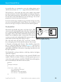
Introducing the gumstix
The gumstix is an extremely small general-purpose computer
system by today’s standards. It is based on Intel’s XScale processor, which is really an ARM CPU. The gumstix is similar to the
kind of hardware that you’d find inside a cell phone, PDA, or GPS.
Not surprisingly, the gumstix is about the same size and shape as
a stick of gum, as shown in Figures 9-1 and 9-2.
The gumstix comes in either 200 or 400 MHz models. The original boards have 4 MB flash memory and 64 MB RAM. Newer
“xm” models feature 16 MB flash memory. A version of Linux
(currently kernel 2.6.11) and the BusyBox suite of applications
are pre-installed.
Figure 9-1. Front side of the
gumstix board.
The gumstix comes with a number of daughterboard options.
Technically, “gumstix” refers only to the CPU board itself. When
paired with a daughter board and a case, the gumstix becomes
a “waysmall” computer. We’ll use the terms interchangeably in
this book.
Figure 9-2. Back side of the gumstix
board, showing Bluetooth and MMC
connectors.
Small Form Factor PCs
Buy the full book online: makezine.com/sff
Chapter 9, Bluetooth LED Sign
For this project we’ve chosen the waysmall STUART daughterboard, which includes two serial ports and a USB device interface;
it also allows you to use Bluetooth in addition to the two serial
ports (earlier offerings were wired up in such a way that the second
serial port and the Bluetooth port used the same UART). Figure
9-3 shows the two boards side by side. Note that the “waysmall
original board” also has two serial ports, but you cannot use the
second port and the Bluetooth interface at the same time.
The waysmall STUART board allows us to use them together.
A number of other daughter boards are available from the
manufacturer, including some with audio, Compact Flash, and
even Ethernet.
The gumstix board also includes a Multi Media Card (MMC) slot.
Here you can add more storage if the on-board flash memory (4
or 16 MB) is not enough. You might want to get an MMC card
for the gumstix, if only because it is a convenient way to transfer
files. Note that even though Secure Digital (SD) memory cards
look exactly like MMC cards, they are not quite the same thing
(see http://en.wikipedia.org/wiki/Secure_Digital). Both MMC and SD
seem to work well from Linux. However, if you want to access
the card from the gumstix boot monitor, perhaps to copy a new
software image, you’d better stick with MMC.
Assembling the System
When you receive your gumstix kit you’ll need to assemble the following
pieces:
• The gumstix processor board
• The waysmall STUART daughter board (part number BRD00003)
• The waysmall case
• The Bluetooth antenna (included with the processor board)
Snapping the two boards together is simple. Align the boards on top of
each other so that the white, rectangular connectors are together. Press the
boards together until you hear a “snap.” Figure 9-4 shows how they look
when connected and with an MMC card inserted into the slot. At this point
you can actually start tinkering with the gumstix if you like. But you might
as well take the time to fit it into its little case.
Figure 9-3. The gumstix and waysmall
daughter board.
Figure 9-4. The gumstix and waysmall
boards connected, with SD memory
card inserted.
What’s a STUART
The gumstix’s PXA processor has four different UARTs,
or Universal Asynchronous
Receiver Transmitters. They
are named FFUART, STUART,
BTUART, and HWUART. The
first serial port is connected to
FFUART. The waysmall STUART
board connects the STUART
to the second serial port. That
means that you cannot use
both Bluetooth and the second
serial port with the original
waysmall board. See http://
www.gumstix.org/tikiwiki/tikiview_faq.php?faqId=13.
Small Form Factor PCs
Buy the full book online: makezine.com/sff
Chapter 9, Bluetooth LED Sign
The two boards should fit snugly inside the white plastic waysmall
case. Figure 9-5 shows our case, which unfortunately didn’t come
with a cutout for the Bluetooth antenna, so we made our own. It
looks like the gumstix site does sell a version of the case with a
hole for the antenna. Either we ordered the wrong one or they only
offered it after we bought ours. Since the case is made of plastic,
it is easy to cut out a notch. We marked the top of the case with
two lines on each side of the antenna and used a small coping saw
to cut out the notch, as shown in Figure 9-6. The result is shown
in Figure 9-7.
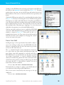
Exploring the gumstix
Figure 9-5. We need to cut a notch in the
waysmall case for the Bluetooth antenna.
To start playing with the gumstix, connect the serial port cable
between the gumstix and your PC, and use a terminal program
such as kermit, screen, or HyperTerminal to set up a serial console
and then apply power. In Figure 9-8 you see a pair of round minidin connectors, which are serial ports. The one that is closest to
the center is ttyS0, or the console port. The other one is ttyS2. The
gumstix serial port is configured for 115,200 bps and 8N1.
The power connector is located on the side of the case. As soon
as you apply power, you should see the following output on the
console:
U-Boot 1.1.1 (Oct
3 2004 - 18:38:12)
*** Welcome to Gumstix ***
U-Boot code: A3F00000 -> A3F1B01C BSS: -> A3F4CB54
RAM Configuration:
Bank #0: a0000000 64 MB
erase_region_count = 32 erase_region_size = 131072
Flash: 4 MB
Hit any key to stop autoboot: 0
### JFFS2 loading 'boot/uImage' to 0xa2000000
Scanning JFFS2 FS: .... done.
### JFFS2 load complete: 809898 bytes loaded to 0xa2000000
## Booting image at a2000000 ...
Image Name:
uImage
Image Type:
ARM Linux Kernel Image (gzip compressed)
Data Size:
809834 Bytes = 790.9 kB
Load Address: a0008000
Entry Point: a0008000
Verifying Checksum ... OK
Uncompressing Kernel Image ... OK
Figure 9-6. Cutting the case with a
coping saw.
Figure 9-7. The Bluetooth antenna
installed.
Starting kernel ...
Small Form Factor PCs
Buy the full book online: makezine.com/sff
Chapter 9, Bluetooth LED Sign
Then you’ll see a more-or-less typical Linux kernel boot sequence.
At the end is a login prompt:
Welcome to the Gumstix Linux Distribution!
gumstix login:
Enter root at the login prompt and gumstix for the password. Then
you should have a no-frills shell prompt from which you can run
commands such as ps, ls, and df. Note that most of these commands
are a part of the BusyBox collection, which we also talked about
in Chapter 6.
Take some time to explore the system and find out what’s there and
what’s not. For example, the gumstix has vi, but not less. It has an
SSH server (Dropbear) and an HTTP server (Boa). It has ifconfig,
ping, and other networking utilities, but no true Ethernet interfaces.
Be sure to take a moment to marvel at how much functionality the gumstix
has on its tiny, 4MB filesystem:
# df -h
Filesystem
/dev/mtdblock2
Size
3.8M
Figure 9-8. Connecting the waysmall
computer to a laptop.
You can get Ethernet on other gumstix
expansion boards, just not on the one
we are using (waysmall STUART).
Used Available Use% Mounted on
3.4M
388.0k 90% /
Customizing the System
Admittedly, there is not much to customize, but you might want to:
• Change the root password.
• Add a non-root user.
• Change the hostname, via /etc/hostname.
• Change the time zone, via /etc/TZ.
In the next section, we’ll show you how to add software packages to the
gumstix.
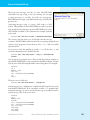
Building Software for the gumstix
The gumstix folks provide a nifty buildroot environment. This is a directory structure that you can copy to an existing Linux box. It provides a
cross-compiler so you can build new binaries for the gumstix. You’ll need
the cross compiler later when we write some code for sending messages to
the sign.
Small Form Factor PCs
Buy the full book online: makezine.com/sff
Chapter 9, Bluetooth LED Sign
The buildroot environment is available through a Subversion source code
control server. To get it, you first need to install a Subversion client on
your other Linux box. For example, to install the Subversion client on
Gentoo, try this:
# USE="-berkdb" emerge -av subversion
With Subversion installed, use this command to check out the gumstix
buildroot environment:
# svn co http://svn.gumstix.com/gumstix-buildroot/trunk gumstix-buildroot
You may notice that the checked-out repository is not very big (about 15
MB). That’s because it doesn’t actually contain all the files that you need
to create the environment. It mostly contains scripts, Makefiles, and empty
directories. These scripts and Makefiles download various source files, such
as a C library, C/C++ compiler, and the Linux kernel, from various other
locations. To finish the installation:
# cd gumstix-buildroot
# make
Unless something is seriously wrong, make should run to completion without
errors. The end result is a J2FFS filesystem image, which will be named
root_fs_arm_nofpu.
The buildroot environment includes some extra software packages that are
not built by default. For example, we were frustrated with the BusyBox /bin/
sh and wanted to use bash instead. Getting bash compiled for the gumstix is
as easy as adding this line to the top-level Makefile:
TARGETS+=bash
Then run make again. You can search the Makefile for other commented-out
TARGETS lines to see what other software is available. You can also list the
*.mk files in the make directory.
After you’ve built new software, how should you copy it to the gumstix?
If you have a program like minicom, you can use the Zmodem file-transfer
protocol to upload it. Another option is to use a MMC card, if you have
one. Unfortunately you cannot (or should not) remove the MMC card while
the system is running. A third option is to connect the gumstix’s USB port
to another computer and use usbnet (see http://www.gumstix.org/tikiwiki/tikiindex.php?page=tutorial) to copy the files over. Finally, another way is to
install the new J2FFS filesystem image on the gumstix flash. Although that
procedure is overkill if you have just one or two files to copy, we’ll describe
it anyway, in case you want to upgrade all of the gumstix software later.
These instructions for installing a new filesystem image come from the gumstix.
org web site. Be sure to check there occasionally for more recent instructions.
Small Form Factor PCs
Buy the full book online: makezine.com/sff
Chapter 9, Bluetooth LED Sign
The gumstix boot monitor, called u-boot, supports uploading new filesystem images with the Kermit transfer protocol. We’ll use the Kermit
terminal emulation program on Linux to do this:
% kermit
C-Kermit 8.0.209, 17 Mar 2003, for Linux
Copyright (C) 1985, 2003,
Trustees of Columbia University in the City of New York.
Type ? or HELP for help.
C-Kermit> set port /dev/tts/0
C-Kermit> set speed 115200
/dev/tts/0, 115200 bps
C-Kermit> set carrier-watch off
C-Kermit> connect
Connecting to /dev/tts/0, speed 115200
Power up your gumstix and interrupt the boot procedure by pressing any
key within three seconds:
U-Boot 1.1.1 (Oct
3 2004 - 18:38:12)
*** Welcome to Gumstix ***
U-Boot code: A3F00000 -> A3F1B01C BSS: -> A3F4CB54
RAM Configuration:
Bank #0: a0000000 64 MB
erase_region_count = 32 erase_region_size = 131072
Flash: 4 MB
Hit any key to stop autoboot: 0
GUM>
From here, issue the following command to tell the gumstix you are uploading
a file:
GUM> loadb a2000000
Then escape back to the Kermit prompt by typing Control-\ C (or whatever
it told you the escape sequence is). At the Kermit prompt, issue the following
commands to send the file:
C-Kermit> robust
C-Kermit> send /tmp/root_fs_arm_nofpu
Kermit displays the upload progress, which should take a few minutes.
When it’s done, you’ll see the C-Kermit prompt again. Connect back to
the serial port, and you’ll see a status message from the gumstix about
the upload:
C-Kermit> connect
Connecting to /dev/tts/0, speed 115200
Escape character: Ctrl-\ (ASCII 28, FS): enabled
Type the escape character followed by C to get back,
or followed by ? to see other options.
---------------------------------------------------## Total Size
= 0x003b2da4 = 3878308 Bytes
## Start Addr
= 0xA2000000
Small Form Factor PCs
Buy the full book online: makezine.com/sff
Chapter 9, Bluetooth LED Sign
Then, issue the following commands to install the new filesystem image
on the gumstix flash. Note, if you have a 16 MB “xm” model, use era
1:2-127 instead:
GUM> echo ${filesize}
3B2DA4
GUM> era 1:2-31
Erase Flash Sectors 2-31 in Bank # 1
.............................. done
GUM> cp.b a2000000 40000 ${filesize}
Copy to Flash... done
GUM>
When it’s done, reboot the gumstix:
GUM> reset
resetting ...
U-Boot 1.1.1 (Oct
3 2004 - 18:38:12)
*** Welcome to Gumstix ***
U-Boot code: A3F00000 -> A3F1B01C BSS: -> A3F4CB54
RAM Configuration:
Bank #0: a0000000 64 MB
erase_region_count = 32 erase_region_size = 131072
Flash: 4 MB
Hit any key to stop autoboot: 0
### JFFS2 loading 'boot/uImage' to 0xa2000000
Scanning JFFS2 FS: ....... done.
### JFFS2 load complete: 710820 bytes loaded to 0xa2000000
## Booting image at a2000000 ...
Image Name:
uImage
Image Type:
ARM Linux Kernel Image (uncompressed)
Data Size:
710756 Bytes = 694.1 kB
Load Address: a0008000
Entry Point: a0008000
Verifying Checksum ... OK
Learning About Bluetooth
One of the most exciting things about the gumstix is its built-in
Bluetooth interface. Bluetooth is sometimes called “Personal Area
Networking,” which is to say that it has a range of about 10 feet. One of
the most common uses for Bluetooth today is for mobile phone headsets
and synchronizing PDAs.
Bluetooth devices support a number of “profiles” designed to facilitate
interoperation. For example, there’s a headset profile, a fax profile, a
serial port profile, a file transfer profile, and many more. We’ll be using
the Serial Port (SP) profile, which creates a virtual serial port over a
Bluetooth connection.
Small Form Factor PCs
Buy the full book online: makezine.com/sff
Chapter 9, Bluetooth LED Sign
The gumstix boots with Bluetooth enabled, so we don’t need to worry about
configuring the kernel or drivers. For example, you should see something
like this when the kernel boots:
Bluetooth: Core ver 2.7
NET: Registered protocol family 31
Bluetooth: HCI device and connection manager initialized
Bluetooth: HCI socket layer initialized
Bluetooth: HCI UART driver ver 2.1
Bluetooth: HCI H4 protocol initialized
Bluetooth: L2CAP ver 2.6
Bluetooth: L2CAP socket layer initialized
Bluetooth: BNEP (Ethernet Emulation) ver 1.2
Bluetooth: BNEP filters: protocol multicast
Bluetooth: RFCOMM ver 1.3
Bluetooth: RFCOMM socket layer initialized
Bluetooth: RFCOMM TTY layer initialized
Those messages indicate Bluetooth support in the kernel. One of the system
rc scripts, /etc/init.d/S30bluetooth, is responsible for configuring devices
and starting various daemon processes. It is executed automatically each
time the system boots. You can also run it manually to start and stop the
Bluetooth-related daemons:
# /etc/init.d/S30bluetooth stop
Stopping Bluetooth subsystem: pand dund rfcomm hidd sdpd hcid /dev/
ttyS3.
To start them again, run:
# /etc/init.d/S30bluetooth start
Set (GPIO,out,clear) via /proc/gpio/GPIO7
Set (GPIO,out,set) via /proc/gpio/GPIO7
Starting Bluetooth subsystem: /dev/ttyS3 hcid sdpd rfcomm pand.
pand is the Personal Area Network daemon. It provides TCP/IP over
Bluetooth. As cool as it sounds, you won’t need it for this project. You can
disable pand by editing /etc/default/bluetooth. Find the PAND_ENABLE variable
and set it to false.
HCI stands for Host Controller Interface. hcitool and hciconfig are tools that
you’ll use to configure Bluetooth on the gumstix. Use this command to see
the address of the local interface:
# hcitool dev
hci0
00:80:37:1C:3A:FF
You may want to add this address to your /etc/bluetooth/hosts file:
# echo 00:80:37:1C:3A:FF gumstix > /etc/bluetooth/hosts
Also run hciconfig, which should remind you of ifconfig:
# hciconfig hci0 up
# hciconfig -a
hci0:
Type: UART
BD Address: 00:80:37:1C:3A:FF ACL MTU: 672:8
Small Form Factor PCs
SCO MTU: 64:0
Buy the full book online: makezine.com/sff
10
Chapter 9, Bluetooth LED Sign
UP RUNNING PSCAN ISCAN INQUIRY
RX bytes:900 acl:0 sco:0 events:99 errors:0
TX bytes:838 acl:0 sco:0 commands:48 errors:0
Features: 0xff 0xfb 0x01 0x00 0x00 0x00 0x00 0x00
Packet type: DM1 DM3 DM5 DH1 DH3 DH5 HV1 HV2 HV3
Link policy: RSWITCH HOLD SNIFF PARK
Link mode: SLAVE ACCEPT
Name: 'Gumstix (0)'
Class: 0x820116
Service Classes: Networking, Information
Device Class: Computer, Palm
HCI Ver: 1.1 (0x1) HCI Rev: 0x8105 LMP Ver: 1.1 (0x1) LMP
Subver: 0x8d40
Manufacturer: Ericsson Technology Licensing (0)
We initially had a lot of difficulty with Bluetooth on the gumstix. It was not
communicating very well with other Bluetooth devices. At first, we suspected
interference from our nearby 802.11 network. But eventually we found some
good suggestions in the gumstix-users mailing list archive. The trick was to
change the setting for HCIATTACH_SPEED in /etc/default/bluetooth:
HCIATTACH_SPEED=230400
Most Bluetooth interfaces for PCs have a USB interface. On the gumstix,
however, Bluetooth uses a Universal Asynchronous Receiver/Transmitter
(UART), which is essentially a serial port. hciattach is the program that
attaches the Bluetooth device to the UART. HCIATTACH_SPEED is the speed
at which these two devices should communicate. The default setting of
921600 is too high, especially for our 200 MHz model gumstix. By lowering
this setting, all of our Bluetooth communications problems disappeared.
These speed problems may have been fixed in the recent gumstix software
releases. However, since this application does not require high speed
communication, we still recommend the 230400 setting.
The hcid daemon manages local Bluetooth devices and responds to certain
Bluetooth queries. It has a configuration file, named /etc/bluetooth/hcid.conf.
This configuration file is where you’ll set the security policy and other parameters, such as the device name. Here is our hcid.conf:
# HCId options
options {
autoinit yes;
security none;
pairing none;
}
# Default settings for HCI devices
device {
name "LED sign";
class 0x820116;
iscan enable; pscan enable;
lm master,accept;
lp rswitch,hold,sniff,park;
}
Small Form Factor PCs
Buy the full book online: makezine.com/sff
11
Chapter 9, Bluetooth LED Sign
The security none line means that other Bluetooth devices can connect
without establishing a trust relationship first. If you set it to auto instead,
you’ll need to place a numeric password in /etc/bluetooth/pin and give that
number to Bluetooth users who are allowed to connect.
One of the most important hcid.conf settings is the link mode (lm), which we
set to master,accept. In a Bluetooth connection, one side is the master and
the other side is the slave. The device that initiates a connection assumes the
role of master. This means that the gumstix becomes the slave for incoming
connections. However, when the gumstix is the slave, it becomes undiscoverable by other devices. Fortunately, Bluetooth allows devices to switch
roles after connecting. The link-mode setting controls how the device treats
incoming connections. When set to master,accept this device accepts incoming connections in slave mode, but then requests to switch roles and become
the master.
Testing the Bluetooth Connection
Eventually, our goal is to be able to send messages to the sign from a phone
or PDA. But if you are new to Bluetooth, you’ll probably have an easier time
if you start playing with another Bluetooth-enabled Linux computer. To
demonstrate how to get Bluetooth up and running, we’ll show you how to
log into the gumstix from another computer.
On your other computer, make sure that Bluetooth is up and running. If
you’ve never done this before, you may want to refer to Chapter 7 of Linux
Unwired (O’Reilly). When you have the Bluetooth interface up and the gumstix nearby, run this command on the other computer:
desktop # hcitool inq
Inquiring ...
00:80:37:1C:3A:FF
clock offset: 0x2269
class: 0x820116
If you don’t get any output the first time, run the command again. Note
that the Bluetooth address (00:80:37:1C:3A:FF here) should match what you
see in the hciconfig output on the gumstix. If not, then either you are running
the command from the wrong computer or you have other Bluetooth
devices nearby.
At this point you can try using l2ping to test low-level Bluetooth connectivity:
desktop # l2ping 00:80:37:1C:3A:FF
Ping: 00:80:37:1C:3A:FF from 00:E0:98:CC:A3:B4 (data size 20) ...
20 bytes from 00:80:37:1C:3A:FF id 200 time 37.74ms
20 bytes from 00:80:37:1C:3A:FF id 201 time 31.09ms
20 bytes from 00:80:37:1C:3A:FF id 202 time 35.18ms
20 bytes from 00:80:37:1C:3A:FF id 203 time 28.39ms
20 bytes from 00:80:37:1C:3A:FF id 204 time 30.48ms
20 bytes from 00:80:37:1C:3A:FF id 205 time 36.68ms
20 bytes from 00:80:37:1C:3A:FF id 206 time 42.81ms
Small Form Factor PCs
Buy the full book online: makezine.com/sff
12
Chapter 9, Bluetooth LED Sign
The next step is to try to establish a “serial port” connection over Bluetooth.
This uses a Bluetooth protocol called Radio Frequency Communications
(RFCOMM). To begin, you must bind a remote Bluetooth address to a local
pseudo-tty device. Here is the command that binds the first RFCOMM tty
to the gumstix Bluetooth address:
desktop # rfcomm bind 0 00:80:37:1C:3A:FF
To print the current bindings, run rfcomm with no arguments:
desktop # rfcomm
rfcomm0: 00:80:37:1C:3A:FF channel 1 clean
Next, configure a serial port communications program, such as minicom,
to open the rfcomm device. It might be either /dev/bluetooth/rfcomm/0 or
/dev/rfcomm0, depending on your particular Linux distribution and version.
The port speed settings are unimportant for Bluetooth. After starting the
communications program, press Enter a few times and you should see a
login prompt:
Welcome to the Gumstix Linux Distribution!
gumstix login:
Now you can log into the gumstix over Bluetooth. If you are brave, you can
even do away with the serial cable connected to ttyS0 and just use Bluetooth
instead. We don’t recommend it, however.
Here are some other commands that may help you debug Bluetooth
problems. When the Bluetooth connection is established, rfcomm shows
some slightly different output:
desktop # rfcomm
rfcomm0: 00:80:37:1C:3A:FF channel 1 connected [tty-attached]
You can also see some connection information with hcitool:
desktop # hcitool con
Connections:
< ACL 00:80:37:1C:3A:FF handle 41 state 1 lm MASTER
Small Form Factor PCs
Buy the full book online: makezine.com/sff
13
Chapter 9, Bluetooth LED Sign
The Pro-Lite LED Sign
For this project we need a LED messaging sign that we can control
through a serial port. Unfortunately, the market for these signs
is not very “hacking friendly.” That is, the sign makers perceive
their customers as people who are not smart enough to write their
own software for controlling the sign. Sign manufacturers do not
openly publish the protocols used to control their signs. The LED
signs are often expensive and sold as a part of a kit that includes
Windows-based software or even a dedicated computer.
Figure 9-9. The Pro-Lite PL-M2014R
LED sign.
Figure 9-9 shows what the PL-M2014R looks like. It’s slightly
more than two feet wide and four inches high. The power and
serial port connectors are on the left side. It also comes with a
remote control (not pictured). Figure 9-10 is a close-up of the sign.
Here you can see the individual pixels (LEDs). The display is 7
LEDs high and 80 wide. The sign is wide enough to display about
13 characters in the normal font.
Purchasing a Pro-Lite sign can be a little tricky. Only a few online
retailers offer it, and you may have to call a salesperson to place
an order. We used Ebay, where a small number of Pro-Lite signs were selling
for between $50 and $175.
Figure 9-10. Close-up of the Pro-Lite
sign showing individual pixels.
Pro-Lite Sign Features
The PL-M2014R has 26 pages, named with the letters A to Z. Each page is
limited to about 1,000 characters. Pages can either be displayed individually, or
chained together. When displayed individually, the message in a given page is
displayed over and over until the sign is instructed to do otherwise. In chained
mode, pages are displayed one after the other, repeating in the same order each
time.
The PL-M2014R boasts 26 different “colors.” In fact, it has five different
colors (red, orange, yellow, lime, green), 3 brightness levels (dim, normal,
bright), and a number of color combinations (rainbow, green on red, etc).
See Table 9-1 (page 257) for the list of available colors.
The sign also has 8 different “fonts” or character sizes. In addition to the
normal font, it has bold, italic, and flashing. These can be combined to
create fonts such as “flashing bold italic.” See Table 9-2 (page 258) for the
full list.
The sign also has 26 different “effects.” Most of these determine how
messages appear or disappear. For example, you can have messages enter
from the left, top, or bottom, or just appear all at once. Also included among
Small Form Factor PCs
Buy the full book online: makezine.com/sff
14
Chapter 9, Bluetooth LED Sign
the possible effects are commands to pause the scrolling display and to
show the date and time. See Table 9-3 (page 259) for the full list of effects.
The Pro-Lite has a trivia mode and comes with a number of pre-loaded
questions and answers. In trivia mode it displays a normal page, then question, then another normal page, and finally the answer. You can delete all
the trivia data to have more memory for your own messages. You can also
program your own trivia questions and answers.
If you just need the sign to display messages that don’t change very often,
you can use the infrared remote control. However, for our purposes, we’ll
need to use the sign’s serial port to send instructions from the gumstix.
The Serial Port
The Pro-Lite sign should come with a serial cable. It has a DB9
Receive
Ground
connector on one end and an RJ11 plug on the other. The gumstix
5
4
3
Transmit
uses a round 8-pin Mini-DIN connector, so this cable won’t work.
You might be able to find a DB9-to-Mini-DIN-8 adapter, but we
Mini-DIN 8 plug
think it’s not too difficult to make a custom cable. One easy way
is to buy a pre-made cable with the Mini-DIN connector, then cut
Figure 9-11. Diagram of the serial
off the other end and crimp an RJ11 plug in its place.
1
2
3
4
RJ11 plug
top view
cable between gumstix and the sign.
The serial cable needs only three wires: receive data, transmit
data, and signal ground. On the mini-din connector these are pins
3 (Transmit), 4 (Ground), and 5 (Receive). These should be connected to
pins 1, 2, and 3 of the RJ11 plug as shown in Figure 9-11. Note that we’re
assuming the RJ11 plug has 4 pins, such that 2 and 3 are in the center, but
some might actually have 6. If you have a 6-pin plug, then add one to the
RJ11 pin assignments.
The PL-M2014R’s serial port defaults to 9,600 bps, which is the highest
speed that it supports.
Using the gumstix’s second serial port on the waysmall STUART board
requires a little bit of voodoo. We have to tell the gumstix processor to
connect the second serial port to the PXA’s STUART. Put the following lines
into /etc/init.d/S60ttyS2 and make the file executable:
#!/bin/sh
#
# Configure /dev/ttyS2
#
if test "$1" = "start" ; then
echo "Configuring /dev/ttyS2:"
modprobe proc_gpio
echo "AF2 in" > /proc/gpio/GPIO46
echo "AF1 out" > /proc/gpio/GPIO47
fi
Small Form Factor PCs
Buy the full book online: makezine.com/sff
15
Chapter 9, Bluetooth LED Sign
Then either reboot or run the script manually:
# /etc/init.d/S60ttyS2 start
Configuring /dev/ttyS2:
Set (AF2,in,set) via /proc/gpio/GPIO46
Set (AF1,out,set) via /proc/gpio/GPIO47
Testing the Sign’s Serial Port
After building the cable, you should test it out to make sure that everything
is connected and working properly. Here’s how you can send some simple
test messages to the sign from the shell:
# T=/dev/ttyS2
# stty -F $T speed 9600 cs8 \
-parenb -cstopb cread clocal \
-crtscts -ignpar -echo nl1 cr3
# stty -F $T opost -ocrnl onlcr
#
#
#
#
cat $T >/dev/null &
echo '<ID01>' > $T
echo '<ID01><PA>testing 1 2 3 ... ' > $T
echo '<ID01><RPA>' > $T
The stty commands configure certain serial port parameters, such as the
speed, flow-control, and other settings. The cat command is necessary to
read characters coming back from the sign. The echo commands send data
to the sign.
Each sign command begins with the token <ID01>. This is the identifier for
sign #1, in case you have multiple signs chained together. The first command
that we send is empty and is there just to wake up the sign in case we haven’t
talked to it for a while. The second command sends some text to the sign.
<PA> refers to page A of the sign’s memory. The third command, <RPA>, means
“run page A.”
Here’s another neat little trick. You can use the following command to
display the current date and time:
# date '+<ID01><PA>%c ' > $T
As you continue playing with the sign, you’ll probably discover some of its
annoying quirks. In particular, updates to the currently displayed page take
effect immediately. In other words, a long message gets cut off as soon as
you send a new one. Normally, this won’t be a problem. But it does become
difficult to use the sign as a frequently updated display. To see what we
mean, try this:
# while true; do date '+<ID01><PA>%c ' > $T ; sleep 1 ; done
Small Form Factor PCs
Buy the full book online: makezine.com/sff
16
Chapter 9, Bluetooth LED Sign
Putting It All Together
By now you should have Bluetooth working. That is, you can log in to the
gumstix over Bluetooth from another computer or perhaps a PDA. You
should also be able to send messages to the LED sign over the serial port. In
this section, we’ll explain how to glue these two together.
Bluetooth Configuration
One of the neat things about Bluetooth is you can run a number of different
services on the same interface using channels. We’ll actually run a number
of “virtual serial ports” over the Bluetooth connection. This allows multiple
PDAs/phones/computers to be connected at the same time. It also means
that we can reserve one channel for logging into the gumstix and the other
channels for talking to the sign. By default the gumstix runs getty on channel 1. We need to set up the other channels using rfcomm.
Earlier we showed you how to use rfcomm bind on another computer to bind
a local RFCOMM device to a remote Bluetooth address. But on the gumstix we don’t know the addresses of the devices that will connect. We want
to accept RFCOMM connections from anyone. In this case we use rfcomm
listen instead. It waits for an RFCOMM connection on a given channel and
then sets up the necessary binding. Our getty process uses rfcomm0 and
channel 1. Use this command to accept incoming connections on rfcomm1
and channel 2:
gumstix # /usr/sbin/rfcomm -r listen 1 2
rfcomm listen waits for a remote connection, stays running as long as the
other side is connected, and then exits when the connection is closed.
Therefore, we need a way to start another rfcomm listen for the next incoming
connection. You can use a while loop in a shell script or, even better, do so
by adding these lines to /etc/inittab:
null::respawn:/usr/sbin/rfcomm
null::respawn:/usr/sbin/rfcomm
null::respawn:/usr/sbin/rfcomm
null::respawn:/usr/sbin/rfcomm
null::respawn:/usr/sbin/rfcomm
-r
-r
-r
-r
-r
listen
listen
listen
listen
listen
1
2
3
4
5
2
3
4
5
6
Reboot or type init -q to have init re-read its configuration file and start
these processes.
Small Form Factor PCs
Buy the full book online: makezine.com/sff
17
Chapter 9, Bluetooth LED Sign
By default, the gumstix only has four RFCOMM device entries in /dev. The
preceding example goes up to rfcomm5, so we’ll need to add at least two
more. One way to do it is by editing sources/device_table.txt in the gumstixbuildroot source tree. Then, of course, build and install a new filesystem
image as described in “Building Software for the gumstix,” earlier in this
chapter. An easier way is to execute a few mknod commands manually.
Even though /dev/ is a memory filesystem, the device entries should persist
between reboots. To add four new RFCOMM devices, run:
/bin/mknod
/bin/mknod
/bin/mknod
/bin/mknod
/dev/rfcomm4
/dev/rfcomm5
/dev/rfcomm6
/dev/rfcomm7
c
c
c
c
216
216
216
216
4
5
6
7
Next, we need to talk about Bluetooth’s Service Discovery Protocol (SDP). This
protocol allows one Bluetooth device to ask another about the services it provides. For example, to see the services offered by your gumstix, you can type:
gumstix # sdptool browse ff:ff:ff:00:00:00
Services are not automatically advertised. Even though we have some
rfcomm listeners, they won’t be announced via SDP until we explicitly add
them. The syntax is:
gumstix # /usr/bin/sdptool add --channel=2 SP
Note that SP refers to Bluetooth’s Serial Port profile. It is essentially a virtual
serial port running over the Bluetooth connection.
You may have noticed that the gumstix advertises an SP on RFCOMM
channel 1 by default. This channel is used by getty so we can log in to the
gumstix over Bluetooth. We think it is a good idea to leave getty running,
but you probably don’t want it announced by SDP because, as we’ll see later,
certain Bluetooth applications will try connecting to the first SP channel
they find. They should connect to the LED sign process, rather than getty.
So we need to delete this channel from the SDP configuration. We recommend
adding the following lines to /etc/init.d/S31bluetooth:
# delete the entry for channel 1, which connects to our getty
# assume its id is always 0x10000
/usr/bin/sdptool del 0x10000
/usr/bin/sdptool
/usr/bin/sdptool
/usr/bin/sdptool
/usr/bin/sdptool
/usr/bin/sdptool
add
add
add
add
add
--channel=2
--channel=3
--channel=4
--channel=5
--channel=6
SP
SP
SP
SP
SP
If you want to get really fancy, you can also use sdptool to add descriptions
for each SP channel:
/usr/bin/sdptool
/usr/bin/sdptool
/usr/bin/sdptool
/usr/bin/sdptool
/usr/bin/sdptool
setattr
setattr
setattr
setattr
setattr
Small Form Factor PCs
0x010001
0x010002
0x010003
0x010004
0x010005
0x100
0x100
0x100
0x100
0x100
"LED
"LED
"LED
"LED
"LED
Sign
Sign
Sign
Sign
Sign
Chan
Chan
Chan
Chan
Chan
1"
2"
3"
4"
5"
Buy the full book online: makezine.com/sff
18
Chapter 9, Bluetooth LED Sign
Getting Messages from Bluetooth to the Sign
The next step in our little project is to write some code that reads messages
from the RFCOMM devices, adds some formatting instructions, and then
writes them to the Pro-Lite sign. Example 9-1 shows one way to accomplish
this in C. We call this program rfcomm-to-sign.
Example 9-1. The rfcommm-to-sign.c program
#include
#include
#include
#include
#include
#include
#include
#include
#include
#include
#include
<stdio.h>
<unistd.h>
<stdlib.h>
<string.h>
<fcntl.h>
<err.h>
<assert.h>
<termios.h>
<syslog.h>
<errno.h>
<sys/file.h>
#define INPUT_BUF_LEN 1024
#define LOCK_PATH "/tmp/sign.lck"
int
get_sign_lock(void)
{
int fd = open(LOCK_PATH, O_RDONLY|O_CREAT);
if (fd < 0)
err(1, LOCK_PATH);
if (flock(fd, LOCK_EX) < 0)
err(1, LOCK_PATH);
return fd;
}
int
open_sign(char *dev)
{
struct termios T;
int fd = open(dev, O_RDWR);
if (fd < 0)
err(1, dev);
syslog(LOG_DEBUG, "sign opened");
if (tcgetattr(fd, &T) < 0)
err(1, "tcgetattr");
cfsetspeed(&T, B9600);
T.c_cflag = CS8 | CREAD | CLOCAL;
T.c_iflag = 0;
T.c_oflag = 0;
T.c_lflag = 0;
T.c_cc[VMIN] = 0;
T.c_cc[VTIME] = 0;
if (tcsetattr(fd, TCSANOW, &T) < 0)
err(1, "tcgetattr");
return fd;
}
Small Form Factor PCs
Buy the full book online: makezine.com/sff
19
Chapter 9, Bluetooth LED Sign
int
open_rfcomm(char *dev)
{
int fd;
for (;;) {
if ((fd = open(dev, O_RDWR)) >= 0)
break;
if (ENODEV != errno)
err(1, dev);
sleep(3);
}
syslog(LOG_DEBUG, "%s opened", dev);
return fd;
}
int
read_rfcomm(int fd, char **line)
{
static char inbuf[INPUT_BUF_LEN];
char c;
int l = 0;
while ((read(fd, &c, 1) > 0) && l < INPUT_BUF_LEN) {
if (c == 0xd || c == 0xa || c == 0x0) {
if (l)
break;
else
continue;
}
inbuf[l++] = c;
}
inbuf[l] = 0;
syslog(LOG_DEBUG, "read {%s}", inbuf);
*line = &inbuf[0];
return l;
}
int
write_sign(int fd, char *buf, int len)
{
int i;
char junk[10];
for (i = 0; i < len; i++) {
if (write(fd, buf+i, 1) < 0) {
syslog(LOG_ERR, "write_sign: %s", strerror(errno));
break;
}
read(fd, junk, 10);
usleep(5000);
}
return i;
}
int
write_sign_str(int fd, char *buf)
{
int len = 0;
syslog(LOG_NOTICE, "writing {%s} to FD %d", buf, fd);
Small Form Factor PCs
Buy the full book online: makezine.com/sff
20
Chapter 9, Bluetooth LED Sign
len = write_sign(fd, buf, strlen(buf));
len += write_sign(fd, "\r\n", 2);
return len;
}
int
write_message(int fd, char *buf, int len, char *page, char *nextpage)
{
int nblen = len + 50;
char *newbuf = malloc(nblen);
write_sign_str(fd, "<ID01>");
snprintf(newbuf, nblen, "<ID01><P%s>%s<FZ><%s>", page, buf, nextpage);
write_sign_str(fd, newbuf);
free(newbuf);
return 0;
}
void
validate_page(char *page)
{
if (strlen(page) > 1 || *page < 'A' || *page > 'Z')
errx(1, "Page should be a single character A-Z");
}
int
main(int argc, char *argv[])
{
int rfcomm;
char *buf = NULL;
char *rfcomm_dev = NULL;
char *sign_dev = NULL;
char *page = NULL;
char *nextpage = NULL;
if (argc != 5) {
fprintf(stderr,
"usage: rfcomm-to-sign rfcommdev signdev page nextpage\n");
exit(1);
}
openlog("rfcomm-to-sign", 0, LOG_DAEMON);
rfcomm_dev = argv[1];
sign_dev = argv[2];
page = argv[3];
nextpage = argv[4];
validate_page(page);
validate_page(nextpage);
rfcomm = open_rfcomm(rfcomm_dev);
for (;;) {
int len;
int lock;
int sign;
write(rfcomm, "ready>\r\n", 7);
if ((len = read_rfcomm(rfcomm, &buf)) < 0)
break;
lock = get_sign_lock();
sign = open_sign(sign_dev);
Small Form Factor PCs
Buy the full book online: makezine.com/sff
21
Chapter 9, Bluetooth LED Sign
write_message(sign, buf, len, page, nextpage);
close(sign);
close(lock);
}
return 0;
}
Here’s how rfcomm-to-sign works. It takes four command-line arguments: an
RFCOMM device pathname, the serial port pathname for the sign, and two
sign page names (A–Z). The first page refers to where the message will be
stored, while the second will be the name of the page to display after this one.
The program begins by opening the RFCOMM device. The open() call
will fail until another device establishes a connection on the corresponding channel, so the program loops until the open() call succeeds. Then it
reads characters from the RFCOMM device. When it reads an end-of-line
character, it writes the message to the sign. Since the sign serial port may
be shared by numerous processes (i.e., other RFCOMM channels), the
program uses file locking to make sure that it has exclusive access to the
serial port while writing.
Note that you can’t compile source code on the gumstix itself. You’ll need
to cross-compile it on another Linux box using buildroot tools, described
in “Building Software for the gumstix,” earlier in this chapter. Assuming
the source code file is named rfcomm-to-sign.c, you can compile it like this
(adjusting the pathnames as necessary):
desktop # XGCC=/some/where/gumstix-buildroot/build_arm_nofpu/staging_
dir/bin/arm-linux-uclibc-gcc
desktop # $XGCC -Wall -o rfcomm-to-sign rfcomm-to-sign.c
Copy the binary to the gumstix using Zmodem, Kermit, or with the MMC
card. You need to run the program for every RFCOMM channel that you
want to use. Assuming you’ve saved the binary as /usr/bin/rfcomm-to-sign,
add these lines to /etc/inittab:
null::respawn:/usr/bin/rfcomm-to-sign
null::respawn:/usr/bin/rfcomm-to-sign
null::respawn:/usr/bin/rfcomm-to-sign
null::respawn:/usr/bin/rfcomm-to-sign
null::respawn:/usr/bin/rfcomm-to-sign
/dev/rfcomm1
/dev/rfcomm2
/dev/rfcomm3
/dev/rfcomm4
/dev/rfcomm5
/dev/ttyS2
/dev/ttyS2
/dev/ttyS2
/dev/ttyS2
/dev/ttyS2
A
B
C
D
E
B
C
D
E
A
As usual, execute init -q to have init start these processes
without rebooting.
Note that rfcomm-to-sign uses syslogd for most errors and
debugging. Check /var/log/messages for errors and notifications
the first few times you run the program. Also keep in mind that
/var/log/messages is on a memory filesystem and is lost each time
you reboot. If you have problems, run the program from a shell
window and see what happens when you send a message to the
sign through Bluetooth.
Small Form Factor PCs
Buy the full book online: makezine.com/sff
Figure 9-12. Mounting the gumstix to
the back of the Pro-Lite sign.
22
Chapter 9, Bluetooth LED Sign
Mounting the gumstix on the Sign
Most likely you’ll want to put the sign up on display for others to see. If so,
you can take a few minutes and attach the gumstix to the back of the sign,
as shown in Figure 9-12. With a few sticky pads and cable ties, you can
hide everything, including the serial cable. You’ll probably want to leave the
Bluetooth antenna sticking up (or down) a little bit for better reception.
Sending Messages to the Sign
Finally we have everything in place to send a message to the sign from
a Bluetooth-enabled device. This section describes a few ways to do just
that!
Figure 9-13. Launching BtSerial.
From PalmOS
If you have a Palm PDA or a phone that runs PalmOS, you can install the
free BtSerial Pro application from http://www.whizoo.com/apps/btserial.php.
As the name implies, it is a Bluetooth serial port communication program.
After launching BtSerialPro, you’ll see the screen shown in Figure 9-13.
Click on Open to locate nearby Bluetooth devices. BtSerialPro opens up
another little window and displays a list of device names, as shown in
Figure 9-14. We gave our gumstix the name “LED sign” (in /etc/bluetooth/
hcid.conf). Click on Connect to establish the Bluetooth connection.
Figure 9-14. Device names shown
by BtSerial.
When BtSerialPro establishes a Bluetooth connection, you should see the
diagnostic messages shown in Figure 9-15. It will say “RFCOMM connection
up!” and tell you about the maximum packet size. The ready> prompt comes
from our rfcomm-to-sign program and provides further evidence that the
communication is working properly.
Now you can enter some text to send to the sign. Either use the Grafitti area
or bring up the keyboard and enter a message. Figure 9-16 shows where
we typed “go cougs!” on the Send line. After clicking on the Send button,
BtSerialPro writes the message over the RFCOMM channel to the sign.
Then our program sends another ready> prompt, indicating it is ready for
another message.
Figure 9-15. BtSerial’s diagnostic
messages.
From KDE
KDE, the K Desktop Environment, has pretty good support for Bluetooth.
If you’ve installed the KDE Bluetooth utilities, you’ll see a little blue “K”
(similar to the Bluetooth “B”) in your KDE panel. If you need help installing
the KDE Bluetooth software, visit http://kde-bluetooth.sourceforge.net/. On
Gentoo Linux we installed net-wireless/kdebluetooth from Portage.
Small Form Factor PCs
Buy the full book online: makezine.com/sff
23
Chapter 9, Bluetooth LED Sign
Clicking on the KDE Bluetooth icon brings up Konqueror (the KDE web/
file browser) with bluetooth:/ in the location box (Figure 9-17). The main
window shows two icons: one for the LED sign and another for the local
Bluetooth device. The icons are chosen based on the class reported by each
device.
Click on the LED sign icon and you’ll see something like the window shown
in Figure 9-18. Now you are browsing the services available on the gumstix.
Although you can click on the Public Browse Group Root and SDP Server
icons, they don’t really lead to anywhere interesting since KDE doesn’t know
how to display the data it receives. The useful icons are the ones that look
like serial port cables. They show up as “Sign Page 1,” etc. for us because we
added those descriptions to our /etc/init.d/S31bluetooth file.
Figure 9-16. Sending a message.
Click on one of the serial port icons to establish an RFCOMM
connection. KDE should then bring up the Bluetooth Serial Chat
window, as shown in Figure 9-19. Here you’ll see the ready>
prompt from rfcomm-to-sign. Type some text into the bottom box
and click on Send. In our example we’re hoping that someone
receives our request for a pizza.
From a Linux Shell
Sending messages to the sign from the Linux shell is almost as
easy as just echoing or cating text to the RFCOMM device file.
However, it depends on how you do it. But before we get to that,
we have to talk a little about stty.
The stty command controls certain terminal device characteristics, such as data rate, flow control, end-of-line processing, and
more. Before using shell commands to read from and write to
RFCOMM devices, you should make sure they have reasonable
stty settings. In particular, echo must be disabled. Otherwise
characters read from the gumstix-side of the connection will be
echoed back to the gumstix, creating an endless loop. You should
also ensure that the read characteristic is enabled. You can set
both of these with one command:
Figure 9-17. Browsing Bluetooth in KDE.
desktop # stty -echo cread < /dev/bluetooth/rfcomm/1
Fortunately, the stty settings are “sticky,” so you should only need
to set them once before using an RFCOMM device.
Now, if you want to interactively write messages to the sign,
simply run:
desktop # cat > /dev/bluetooth/rfcomm/3
Small Form Factor PCs
Buy the full book online: makezine.com/sff
Figure 9-18. Browsing Bluetooth
services.
24
Chapter 9, Bluetooth LED Sign
Then type your messages, one line at a time. The RFCOMM
connection stays up as long as cat stays running. You can type
as many messages as you like, but with our one-page-perRFCOMM-device design, each additional message overwrites the
previous one.
Generating messages using echo from a shell script is a little
trickier. The problem is that the RFCOMM device must stay open
long enough for the gumstix to open the RFCOMM device on its
side and then read from it. This command, for example, probably
won’t work:
desktop # echo "this does not work" > /dev/bluetooth/rfcomm/2
The reason is that the device gets closed right after the message
is written. The RFCOMM connection does not stay up long enough for our
rfcomm-to-sign program to return from its short sleep() and successfully
open the device.
Figure 9-19. KDE Bluetooth chat.
An easy way to solve this problem is to add a sleep call after the echo and
run both commands from a subshell, like this:
desktop # (echo "this works better" ; sleep 5) > /dev/bluetooth/
rfcomm/2
Our rfcomm-to-sign program uses a three-second sleep between attempts to
open the RFCOMM device, so five seconds here should be sufficient. You may
want to write a little shell script that hides some of the ugliness. For example:
#!/bin/sh
set -e
RNUM=$1 ; shift
stty -echo
exec > /dev/bluetooth/rfcomm/$RNUM
cat
sleep 5
Then you can use it like this:
desktop # echo "this works better" | ./ledsign.sh 1
Another way is to use a slightly more complicated shell script that also reads
from the RFCOMM device. If we can make it read the ready> prompt before
writing the message, we can be sure that the message is actually received by
rfcomm-to-sign. Here is one way to do it:
#!/bin/sh
set -e
RNUM=$1; shift
read MSG
exec < /dev/bluetooth/rfcomm/$RNUM
exec > /dev/bluetooth/rfcomm/$RNUM
stty -echo cread
read prompt
echo "$MSG"
read prompt
Small Form Factor PCs
Buy the full book online: makezine.com/sff
25
Chapter 9, Bluetooth LED Sign
The script first reads the message from stdin. Then it reassigns stdin and
stdout to the RFCOMM device. It reads the prompt from rfcomm-to-sign,
writes the message, and then waits for the next prompt. We also added the
necessary stty settings for good measure. Here’s how you would use it:
desktop # date | ./ledsign.sh 4
One drawback to the second version is that it might get stuck on one of
the read prompt calls. Since there is no timeout, the script will block until
interrupted. If you are sending messages to the sign automatically (versus
interactively), you may want to use the sleep() approach instead.
Pro-Lite Control Protocol
As we mentioned earlier, you can use different colors, fonts, and effects with
the Pro-Lite sign by inserting special codes in your message. For example,
to display a message in red, you could send:
<CB>50% Off Today Only
The following tables show the control codes for the sign’s colors, fonts,
effects, and a few miscellaneous things.
Colors
Table 9-1 lists the 26 color codes supported by the Pro-Lite sign. Note that
the sign really only has five colors: red, orange, yellow, lime, and green.
The yellow and lime colors are almost the same. One of the colors, called
Rainbow, uses all five colors at once.
In addition to the five colors, the sign also has three different brightness
levels. Some of the color codes use shadows and different background colors
as well. Some of these look okay, and some look hideous. You should try
them out for yourself to see which ones you like.
Table 9-1. The Pro-Lite’s color codes
Code
Color
<CA>
Dim red
<CB>
Red
<CC>
Bright red
<CD>
Orange
<CE>
Bright orange
<CF>
Light yellow
<CG>
Yellow
<CH>
Bright yellow
<CI>
Lime
<CJ>
Dim lime
<CK>
Bright lime
Small Form Factor PCs
Buy the full book online: makezine.com/sff
26
Chapter 9, Bluetooth LED Sign
Code
Color
<CL>
Bright green
<CM>
Green
<CN>
Dim green
<CO>
Yellow/green/red
<CP>
Rainbow
<CQ>
Red/green 3-D
<CR>
Red/yellow 3-D
<CS>
Green/red 3-D
<CT>
Green/yellow 3-D
<CU>
Green on red
<CV>
Red on green
<CW>
Orange on green
<CX>
Lime on red
<CY>
Green on red 3-D
<CZ>
Red on green 3-D
Fonts
Table 9-2 lists the Pro-Lite’s font codes. Note that these all start with the
letter “S,” probably because the Pro-Lite documentation also refers to these
as size codes.
The font choices are pretty simple: normal, bold, italic, and bold plus italic.
Any of those can be made to flash as well, for a total of 8 font codes. The
bold font looks okay, but italic is a little too hard to read. The bold plus italic
font displays about half as many characters on the sign as the normal font.
Table 9-2. The Pro-Lite’s font codes
Code
Font
<SA>
Normal
<SB>
Bold
<SC>
Italic
<SD>
Bold italic
<SE>
Flashing normal
<SF>
Flashing bold
<SG>
Flashing italic
<SH>
Flashing bold italic
Effects
Table 9-3 lists the 26 different effects. As you use the sign more and more,
you’ll probably want to take advantage of these effects to break up the
monotony of a simple scrolling display.
Small Form Factor PCs
Buy the full book online: makezine.com/sff
27
Chapter 9, Bluetooth LED Sign
Table 9-3. The Pro-Lite’s effect codes
Code
Effect
<FA>
AUTO (L)
<FB>
OPEN (L)
<FC>
COVER (L)
<FD>
DATE
<FE>
CYCLING (L)
<FF>
CLOSE LEFT (T)
<FG>
CLOSE RIGHT (T)
<FH>
CLOSE CENTER (T)
<FI>
SCROLL UP (L)
<FJ>
SCROLL DOWN (L)
<FK>
OVERLAP (L)
<FL>
STACKING (L)
<FM>
COMIC 1 (L)
<FN>
COMIC 2 (L)
<FO>
BEEP
<FP>
PAUSE (T)
<FQ>
APPEAR (L)
<FR>
RANDOM (L)
<FS>
SHIFT (L)
<FT>
TIME
<FU>
MAGIC (L)
<FV>
THANK YOU
<FW>
WELCOME
<FX>
SLOW SPEED
<FY>
NORMAL SPEED
<FZ><x>
CHAIN to page x (T)
Some of these effects are meant to be used at the beginning of a message.
They affect the way that the message appears on the display. Such effects are
marked with (L) in the table. For example, the OPEN effect erases the display
and then causes the message to appear one column at a time from both ends
leading toward the center. The COVER effect is similar, except that the display is not erased first. The AUTO effect introduces the message with a randomly chosen effect and color each time. The RANDOM effect, on the other
hand, introduces the message by turning on one pixel at a time in a random
order. MAGIC is similar to AUTO, except that it only affects the color.
The effects marked with (T) are meant to be used at the end of a message.
They affect the way that the message disappears. For example, CLOSE
LEFT erases the message one row at a time from right to left. You may find
Small Form Factor PCs
Buy the full book online: makezine.com/sff
28
Chapter 9, Bluetooth LED Sign
the PAUSE effect to be very useful. It freezes the display for one second. The
Pro-Lite documentation says that this is a trailing effect, but you can use it
in the middle of a message too.
Two effects are named DATE and TIME. These display the date and time
based on the sign’s internal clock. Apparently these effects use hardcoded
colors that you cannot change. See the next section for the command that
sets the sign’s clock.
The CHAIN effect is somewhat special because it must be followed by
another code representing the next page to display. For example, <FZ><C>
tells the sign to display page “C” next.
Note that some of the codes have different effects in older versions of the ProLite protocol. For example, Walt Stoneburner’s site describes an earlier version
of the sign software where DATE and TIME were together in a single effect.
Miscellaneous
Table 9-4 lists a few miscellaneous protocol commands. We use the first
one (<Px>) in rfcomm-to-sign.c to program each page. The second one (<RPx>)
instructs the sign to run (or display) the specified page immediately.
Table 9-4. Miscellaneous protocol commands
Code
Description
<Px>
Program page x
<RPx>
Run (display) page x
<TYYYYMMDDWhhmmssX>
Set the time
The code for setting the time is a little bit different than the others. Most
of the commands must be preceded by a sign identifier, such as <ID01>. The
time-setting command, however, must not. That means that you can’t use
rfcomm-to-sign to set the time since the program inserts the ID string before
each command.
In the command string given in Table 9-4, the T represents an actual “T” (for
time). All other letters must be replaced by numbers. YYYYMMDD represents
the year, month, and day. W represents the day of the week (1–7). hhmmss
represents the hour, minute, and seconds. X is either 0 (for AM/PM mode)
or 1 (for 24-hour mode).
Make sure that the gumstix clock is set correctly before using the following
commands to set the sign’s clock. (We’ve noticed that the gumstix’ clock is
reset when it reboots.) Since you can’t use rfcomm-to-sign to set the clock,
you can use this trick instead:
# T=/dev/ttyS2
# stty -F $T speed 9600 cs8 -parenb -cstopb cread clocal \
-crtscts -ignpar -echo nl1 cr3 opost -ocrnl onlcr
# cat $T >/dev/null &
# date '+<T%Y%m%d%u%H%M%S0>' > $T
# kill %1
Small Form Factor PCs
Buy the full book online: makezine.com/sff
29
Chapter 9, Bluetooth LED Sign
Extra Credit
If you’ve followed all the steps in this chapter, you have a pretty neat
Bluetooth-enabled, Linux-powered LED sign. Here are some ideas for making the project even better.
Using OBEX Transfers
We’ve shown you how to transfer data from a handheld device to the gumstix using Bluetooth’s serial port emulation. While this seems to work okay,
it is not the only option. If your phone/PDA doesn’t have an application
that supports the Bluetooth serial port (SP) profile, you can use the Object
Exchange (OBEX) protocol instead.
OBEX is, essentially, a file transfer protocol. Bluetooth devices use OBEX
to send images, vCards (i.e., address book entries), calendar data, and other
types of files. OBEX was originally developed for use with infrared (IrDA)
interfaces, but has been adopted by Bluetooth as well.
Your gumstix should already have everything you need to accept files via
OBEX. In particular, make sure that the OBEX Push Daemon, /usr/sbin/opd,
is present. If not, you’ll need to go to the gumstix buildroot environment
as described in “Building Software for the gumstix,” earlier in this chapter,
and build a new filesystem. Make sure that openobex has been added to the
TARGETS variable in the top-level Makefile:
OBEX Versus SP
If you have the option to use either
OBEX or SP, you may prefer to use
OBEX for long or repeated messages.
You can save a long message as a
note or memo and then send it many
times. SP mode, on the other hand, is
better for usage that resembles a conversation. Once the serial port session
has been established, you can quickly
send multiple messages.
# For Bluetooth
TARGETS+=bluez-utils openobex
If you changed the Makefile, build a new root filesystem and upload it to
the gumstix flash memory. Recall that by updating the flash memory, any
files that you have added or edited will be lost. If you have an MMC or SD
card, you may want to make a copy of these files before updating the flash
memory:
• /etc/default/bluetooth
• /etc/bluetooth/hosts
• /etc/bluetooth/hcid.conf
• /etc/init.d/S60ttyS2
• /etc/inittab
• /etc/init.d/S31bluetooth
Small Form Factor PCs
Buy the full book online: makezine.com/sff
30
Chapter 9, Bluetooth LED Sign
You’ll need to make an important change to /etc/bluetooth/hcid.conf. One
of the settings there is the device class. Bit #20 (0x100000 hex) in the class
value should be turned on to indicate OBEX support. The default value is
0x820116, so you can change it to 0x920116:
# Local device class
class 0x920116;
Reboot or restart the Bluetooth daemons after editing hcid.conf. Then, after
verifying that opd is installed, add these lines to /etc/init.d/S31bluetooth:
test -d /tmp/obex || mkdir /tmp/obex
/usr/sbin/opd --mode OBEX --channel 10 --path /tmp/obex --sdp --daemon
Files sent to the gumstix will appear in the /tmp/obex directory. The --sdp
option instructs opd to automatically advertise the OBEX service via the
Service Discovery Protocol. You may want to run opd manually a few times
before running it from S31bluetooth. Use the same command line, but without the --daemon option.
When opd is running, make sure that OBEX appears in the list of Bluetooth
services:
# sdptool browse ff:ff:ff:00:00:00
...
Service Name: OBEX Object Push
Service RecHandle: 0x10006
Service Class ID List:
"OBEX Object Push" (0x1105)
Protocol Descriptor List:
"L2CAP" (0x0100)
"RFCOMM" (0x0003)
Channel: 10
"OBEX" (0x0008)
Profile Descriptor List:
"OBEX Object Push" (0x1105)
Version: 0x0100
Now you are ready to attempt a file transfer from your phone or PDA. If
you have a PDA running PalmOS, go to the Memo Pad and create a new
memo. While still viewing the memo, press the Menu button. You should
see a Send Memo option. Select it and then find your gumstix in the device
list. Click on OK. If everything works, you should have a new file in the
/tmp/obex directory.
Bluetooth-enabled mobile phone users may have to work a little harder to
use OBEX transfer. If your phone has a way to store notes or memos, it
probably also has an option to send them via Bluetooth. Otherwise, you
can try sending an address book entry to the gumstix. It should show up on
the other side as a vCard. If you plan to use this technique to get messages
to the LED sign, you’ll need to write some code to strip out the vCard tags
and other formatting.
Small Form Factor PCs
Buy the full book online: makezine.com/sff
31
Chapter 9, Bluetooth LED Sign
If you’re having a hard time getting OBEX to work, kill the opd daemon
process and run it from the command line. You should see output like this
during a successful transfer:
obex_event: 1 6( EV_UNKNOWN) 0(
CMD_CONNECT)
Unknown event 6 !
obex_event: 1 1( EV_REQHINT) 0(
CMD_CONNECT)
obex_event: 1 2(
EV_REQ) 0(
CMD_CONNECT)
opd[338]: OBEX connect from 00:07:E0:00:1F:F8
obex_event: 1 3( EV_REQDONE) 0(
CMD_CONNECT)
obex_event: 1 1( EV_REQHINT) 2(
CMD_PUT)
obex_event: 1 0(EV_PROGRESS) 2(
CMD_PUT)
obex_event: 1 0(EV_PROGRESS) 2(
CMD_PUT)
obex_event: 1 2(
EV_REQ) 2(
CMD_PUT)
HEADER_LENGTH = 15
Handle_OBEX_CMD_PUT() Skipped header 05
HEADER_TYPE = 'text/plain' #11
00: 74 65 78 74 2f 70 6c 61 69 6e 00
text/plain.
Handle_OBEX_CMD_PUT() Skipped header c0
Filename = /tmp/obex/memo via.txt
Wrote /tmp/obex/memo via.txt (15 bytes)
obex_event: 1 3( EV_REQDONE) 2(
CMD_PUT)
obex_event: 1 1( EV_REQHINT) 1(CMD_DISCONNECT)
obex_event: 1 2(
EV_REQ) 1(CMD_DISCONNECT)
opd[338]: OBEX disconnect from 00:07:E0:00:1F:F8
obex_event: 1 3( EV_REQDONE) 1(CMD_DISCONNECT)
obex_event: 1 4( EV_LINKERR) 0(
CMD_CONNECT)
opd[338]: lost link to 00:07:E0:00:1F:F8
0
0
0
0
0
0
0
0
0
0
0
0
0
Once OBEX is working to the point where files appear in the /tmp/obex
directory, you’ll need to write some scripts that send the message to the
sign. The following shell script should help get you started:
#!/bin/sh
# scan-obex.sh: periodically scan the OBEX dropoff
# directory and send incoming messages to the sign
cd /tmp/obex
test -d /tmp/trash || mkdir /tmp/trash
while true ; do
sleep 1
for k in * ; do
test "$k" = "*" && continue
echo "found file: $k"
msg=`cat "$k" | tr '\r' ' ' | tr '\n' ' '`
msg=`echo $msg`
echo "sending message: $msg"
/usr/local/bin/to-sign.sh A $msg
mv "$k" /tmp/trash
sleep 30
done
done
Small Form Factor PCs
Buy the full book online: makezine.com/sff
32
Chapter 9, Bluetooth LED Sign
Note that the to-obex.sh script assumes that files might contain whitespace
characters. It also changes newlines and carriage returns in the message to
spaces. It calls another script, named to-sign.sh, to actually send the message to the sign:
#!/bin/sh
# to-sign.sh: write a message to the LED sign tty
T=/dev/ttyS2
PAGE=$1; shift
MSG="$*"
stty -F $T speed 9600 cs8 -parenb -cstopb -cread clocal crtscts \
-ignpar -echo nl1 cr3
stty -F $T opost -ocrnl onlcr
cat $T >/dev/null &
echo "<ID01>" >$T
echo "<ID01><P${PAGE}>
$MSG<FP>" >$T
echo '<ID01><RP${PAGE}>' >$T
Remove Special Characters from Received Messages
Most of the Pro-Lite control codes do useful things like change colors and
add special effects. However, it probably won’t take a really curious person
very long to find a number of ways to hack the sign. For example, a simple
command can delete all pages from memory.
To protect against this, you may have to block certain Pro-Lite commands.
You could just block all commands by disallowing the < and > characters,
for example. But that seems like overkill since many of the commands are
useful.
Filtering Offensive Messages
If you plan to use the sign in a public setting where anyone can post a message, you can be sure that someone will write an offensive message just to
see if they can. You may be forced to add some filtering to the code. For
example, a simple method for detecting profanity is to compare words in
messages with those in a “bad words” file.
One Less Power Supply
It would be nice to have only one power cord running from the wall to the
sign. The Pro-Lite uses a 9V power supply, while the gumstix uses 5V. With
a handful of parts and a little soldering, you should be able to build a gizmo
that takes 9V from the sign’s supply and provides 5V to the gumstix. It
might be as simple as an LM7805 voltage regulator plus a heat sink.
Small Form Factor PCs
Buy the full book online: makezine.com/sff
33
Chapter 9, Bluetooth LED Sign
Prepending the Device Name to Messages
If you use the sign in a public setting, it may be nice to automatically insert
the Bluetooth device name into every message. This adds some accountability
and makes the message display similar to a chat room.
Each time rfcomm-to-sign gets a new RFCOMM connection it can run
rfcomm show to get the address of the device connected on its channel. Then
it can run hcitool name x:x:x:x:x:x to get the connected device’s name.
If prepending device names is too awkward, you may want to at least
consider giving each page a different color. At the very least this allows
viewers to tell when one message ends and another begins. Of course, if
messages include color codes, such as <CB>, the sender can override the
default color for a page, anyway.
Aging Messages from the Sign
Depending on your particular use of the sign, it may make sense to put a
time limit on how long a particular message will be displayed. The sign
doesn’t have any built-in features to support this, so you’ll need to implement
it in software on the gumstix.
One approach is to modify rfcomm-to-sign so that it keeps track of how
long it has been trying to open the RFCOMM device. After some amount
of time, say 10 minutes, it can send a message to the sign to erase the corresponding page. If you are using the page-chaining technique, you don’t
want to actually erase the page, but instead send an empty message followed
by an instruction to jump to the appropriate page.
Scaling the Software
Our design has a one-to-one mapping of RFCOMM channels to sign pages.
Although our examples use only five channels and pages, you could easily
extend this to all 26 of the Pro-Lite’s pages.
The drawback is that each page requires two processes running from /etc/
inittab: the rfcomm listen process, and rfcomm-to-sign. At some point this
may become a significant burden for the lil’ gumstix.
A Bluetooth device cannot be connected to more than seven other
devices at once. However, each
device can use multiple RFCOMM
channels and some devices may be
disconnected when idle.
One way to reduce the number of processes is by modifying rfcomm-to-sign
so that a single process manages all channels and pages. This makes the
program more complicated since it will need to use nonblocking I/O and
select(). On the upside, however, a single process makes certain sign-related
tasks easier. For example, you can chain pages together based on the number
of active messages or change the order in which they are displayed.
Small Form Factor PCs
Buy the full book online: makezine.com/sff
34
Chapter 9, Bluetooth LED Sign
With a single rfcomm-to-sign process, you can also do away with the onechannel-per-page limitation. Instead, messages might be displayed in the
order they are received, regardless of who sends them.
You can, in theory, have up to 60 RFCOMM channels. However, since each
channel requires a separate rfcomm listen process, this may not be realistic.
If you really need that many, you’ll probably want have a look at the rfcomm
source code and see if you can write a new program that manages multiple
listeners, or perhaps build it directly into a program like rfcomm-to-sign.
Small Form Factor PCs
Buy the full book online: makezine.com/sff
35