1
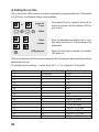
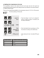
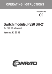
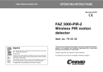
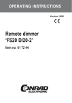
OPERATING INSTRUCTIONS Version 12/06 Wireless PIR motion detector „FS20 PIRI-2“ Item no. 62 05 94 Table of contents Page 1. Introduction ................................................................................................................. 4 2. Prescribed use ............................................................................................................ 5 3. Scope of delivery ........................................................................................................ 5 4. Explanation of icons .................................................................................................. 6 5. Safety instructions ..................................................................................................... 6 a) General information ............................................................................................... 6 b) Batteries and rechargeable batteries ................................................................... 7 6. Features and functions .............................................................................................. 8 7. Factory setting ............................................................................................................ 9 8. General notes on installation ................................................................................. 10 9. Installing the ‘FS20 PIRI-2’ ...................................................................................... 11 a) b) c) d) Installation with wall bracket ............................................................................... 11 Control, display and settings ............................................................................... 13 Opening the battery compartment ...................................................................... 14 Inserting the batteries .......................................................................................... 14 10. Initial operation ......................................................................................................... 15 a) Quick installation with factory settings ................................................................ 15 b) Function test ........................................................................................................ 15 11. The FS20 address system ....................................................................................... 17 12. Integrating into the address system ...................................................................... 19 a) Setting the house code ........................................................................................ 19 b) Setting the addresses .......................................................................................... 20 1. Setting a single address .................................................................................. 20 2. Assigning function groups and master addresses ......................................... 21 13. Individual settings .................................................................................................... 24 a) Manual switching ................................................................................................. 24 b) Activating a channel ............................................................................................ 25 c) Setting the brightness value ................................................................................ 26 1. Saving the threshold value for one of the two channels ................................ 26 2. Saving the same threshold for both channels ................................................ 27 d) Setting the on-time .............................................................................................. 28 2 Page e) f) g) h) i) Setting the transmission interval .......................................................................... 29 Setting the transmit command ............................................................................. 31 Setting the filter time ............................................................................................. 33 Resetting the factory settings ............................................................................... 34 Programming the receiver timer ........................................................................... 35 14. ‘Low Bat’ display and changing batteries ............................................................. 35 15. Information on the range .......................................................................................... 36 16. Handling ...................................................................................................................... 37 17. Maintenance and cleaning ....................................................................................... 37 18. Disposal ...................................................................................................................... 38 a) General information .............................................................................................. 38 b) Batteries and rechargeable batteries .................................................................. 38 19. Technical specifications ........................................................................................... 39 20. Declaration of conformity (DOC) ............................................................................. 39 3 1. Introduction Dear customer, Thank you for purchasing this product. This product meets the requirements of both current European and national guidelines. In order to preserve this condition and ensure the safe operation of the product we kindly ask you to carefully follow these operating instructions! Please read the operating instructions completely and observe the safety and operation notes before using the product! All company names and product names contained herein are trademarks of the respective owners. All rights reserved. Should you have any further questions, please contact our technical advisory service: Germany: Tel. no.: +49 9604 / 40 88 80 Fax. no.: +49 9604 / 40 88 48 e-mail: [email protected] Mon. to Thur. 8.00am to 4.30pm Fri. 8.00am to 2.00pm 4 2. Prescribed use The 2-channel PIR motion detector ‘FS20 PIRI-2’ is a component of the FS20 wireless control system. It can control up to 2 radio receivers in the FS20 system with separately adjustable criteria. The PIR motion detector registers infrared radiation (heat) of moving people and warmblooded animals (for the latter, a minimum size is required to trigger the PIR motion detector). Batteries must be used to power the device. Make sure that the product does not get damp or wet. The product is only suitable for use in dry indoor areas. Any use other than the one described above may damage the product and can also increase the risk of short-circuit, fire, electric shock, etc. No part of the product may be modified or adapted. The device may only be operated when its casing is fully closed. All the safety instructions and installation notes in this manual must be observed without fail. 3. Scope of delivery • PIR motion detector ‘FS20 PIRI-2’ with installation bracket • User manual 5 4. Explanation of icons The icon with a lightning flash in a triangle is used to alert you to potential personal injury hazards such as electric shock. The icon with an exclamation mark in a triangle points to important instructions in this user manual that must be observed. The ‘hand’ symbol provides special information and advice on operating the device. 5. Safety instructions The product’s guarantee becomes invalid, if the product is damaged as a result of the failure to observe these operating instructions! We do not assume any liability for any resulting damages! Nor do we assume liability for damage to property or personal injury caused by improper use or failure to observe the safety instructions. In such cases the product’s guarantee becomes invalid. Dear customer, the following safety instructions are intended to protect you as well as the device. Please take time to read through the following points: a) General information • If, during mounting, connection or installation you are not sure or have doubts about how to proceed, contact a skilled technician. • For safety and licensing (CE) reasons any unauthorised alterations to and/or modification of the product are not permitted. • Make sure that the product does not get damp or wet. It is only suitable for installation and operation in dry indoor areas. • This product is not a toy and should be kept out of the reach of children. 6 • Do not leave packaging material lying around. This may become a dangerous plaything in the hands of children. • Handle the product with care; knocks, blows or even a fall from a low height can damage it. b) Batteries and rechargeable batteries • Keep batteries/rechargeable batteries out of the reach of children. • Make sure that the polarity is correct when inserting the batteries/rechargeable batteries. • Do not leave batteries/rechargeable batteries lying around as they could be swallowed by children or pets. In such case seek immediate medical care. • Leaking or damaged batteries/rechargeable batteries may cause acid burns, if they come into contact with skin. Therefore, please make sure you use suitable protective gloves. • Make sure that batteries/rechargeable batteries are not short-circuited or thrown into a fire. They might explode! • Never disassemble batteries/rechargeable batteries! • Conventional batteries must not be recharged. They might explode! • If the device is not used for a longer period of time (when stored, for example), remove the inserted batteries/rechargeable batteries to prevent them from leaking and causing damage. The PIR motion detector can be operated with rechargeable batteries. However, due to their lower voltage (rechargeable battery = 1.2V, battery = 1.5V) and lower capacity, the period of operation and range are reduced. Therefore, to ensure safe operation, please only use high-quality alkaline batteries. 7 6. Features and functions • Detects heat motion (for example the movement of a person or an animal in front of a static background of a different temperature) and activates an alarm • Range up to 12m • Detection angle approx. 90° • Detection area infinitely adjustable +/-45° • Creep zone protection • May be installed on walls or ceilings • Integration in the code and addressing system of the FS20 wireless control system enables a clear boundary from adjacent running systems as well as, for instance, the control of several particular receivers • 2 switching channels with separately adjustable criteria: - Each channel may be activated separately Activation only in dark, or also whilst light Daylight activation value freely adjustable On-time adjustable between 0.25 seconds and 4.25 hours Selectable receiver switching pattern (transmit command) Transmission interval of subsequent signals of the motion detector is adjustable - Adjustable filter time for the integrated brightness sensor - Timer programming of the receiver (1 second to 4.5 hours) Optional slow-on/slow-off function for dimmer - Manual switching of the receiver via control buttons on the motion detector possible Caution! The ‘FS20 PIRI-2’ is only suitable for use in dry indoor areas! This device is not waterproof! It must not get damp or wet! 8 7. Factory setting The ‘FS20 PIRI-2’ is immediately ready for use and configured with the following factory default settings: • Channel 1 activated (ON) • Activation also in lighted areas (dawn/dusk switch function inactive) • Receiver on-time triggered by movement in front of the detector: 1 minute, then load is switched off (transmit command). • If further movements are registered during this minute, a new power-on command will be transmitted, at most every 24 seconds, thereby restarting the 1-minute on-time (transmission interval). • Channel 2 is inactive (OFF). The terms printed here in bold are the adjustment criteria for each channel, whose programming is described separately in the following user manual. 9 8. General notes on installation • The front coverage lenses of the ‘FS20 PIRI-2’ are supplied with 4 detection levels with 9 upper, 8 middle, 5 lower and 2 creep zone segments. This enables a detection angle of 90° to be achieved at a range of up to 12m. • For additional security, the ‘FS20 PIRI-2’ is equipped with so-called ‘creep protection’ so that an intruder cannot ‘creep’ under the detection area of the main lens. An additional integrated lens is directed downward, under the main detection area. This mini dome lens has 17 segments which cover an area of 3.75m x 3.75m when installed at a height of 2m. • In order to avoid unnecessary activation by household pets, keep them away from protected areas when possible. If this is not possible, try adjusting the height to allow the device appropriate coverage. Cover the creep zone where appropriate. Please remember that household pets may also jump on, for instance, cabinets or chairs and in so doing, arrive in the detection area. Choose a suitable installation location. • To minimize false alarms, the PIR detector must not be installed where it may be exposed to direct sunlight, car headlamps or similar, nor near heat sources (for example over heaters). The detection area should be aimed at a wall or on the floor, but not directly on windows, heaters or other sources of heat. • The performance of the detection is dependent upon the temperature difference between the moving object and the respective background. • Detection through glass is not possible (in that case, the IR sensor only recognises the temperature of the glass). • Please remember not to install the ‘FS20 PIRI-2’ directly on or near large metal objects (heating, aluminium laminated board walls, etc.) because this reduces the radio range. 10 9. Installing the ‘FS20 PIRI-2’ a) Installation with wall bracket The PIR motion detector is equipped with a bracket that is suitable for installation on a wall or ceiling. Because the detector may be adjusted more than 45 degrees when in the bracket, the detection area may be set at almost any angle from the wall and may also be further adjusted after installation. The ceiling installation option enables the device to be freely mounted within the room to avoid common traffic paths within the detection area, for example, in a hallway. 1 2a ø 5 mm 20 mm ø 5 mm 2b • Select an appropriate installation location for the PIR motion detector in the monitored room. • Pull the wall/ceiling bracket up and off the base device of the PIR motion detector (1). • Position the bracket in a suitable location on a wall or ceiling in the room. 11 • The location of the drill holes on the wall or ceiling can be marked through the visible screw holes in the bracket. For wall installation (2a) use both holes in the wall bracket. For ceiling installation (2b) a hole needs to be drilled in the middle of the top of the bracket. Make sure that the wall or ceiling can support the device at the marked drill hole locations and avoid all electrical, gas, water and drain lines. • Drill each 5mm hole at least 35 mm deep and insert 2 appropriately sized dowels. • Position the wall/ceiling bracket over the drill holes and fasten it in place with the screws. 12 b) Control, display and settings 3 1 2 4 6 5 A C B CH1 CH2 13 1 ‘1’ button 2 ‘2’ button 3 ‘3’ button 4 ‘4’ button 5 DIP switch It is used to switch both channels on and off (DIP switch 1 = channel 1, DIP switch 3 = channel 2) and to switch the dawn/dusk switching function on and off (DIP switch 2 = channel 1, DIP switch 4 = channel 2). 6 LED c) Opening the battery compartment To open the battery compartment, first pull the wall/ceiling bracket in an upward direction (A). Then slide the battery compartment cover upwards (B) and remove it (C). d) Inserting the batteries The PIR detector requires 3 size AA batteries. We recommend using high-quality alkaline batteries to ensure longest possible battery life. • Remove the battery compartment cover as described on the previous page. • Ensure that the 4-way DIP switch settings in the centre battery compartment reflect the desired operating modes and if necessary, set them as described in section 13 (Individual settings). • Insert the batteries in the battery compartment observing the correct polarity (plus/+ and minus/-, see figure on right). • The battery compartment remains open. 14 After inserting the batteries, the device needs about 75 seconds before it is ready for use. Within this time no motions will be detected. 10. Initial operation a) Quick installation with factory settings The motion detector is immediately ready for operation with the factory default settings described in section 7. The transmission signals are encrypted using a house code that is randomly assigned when the batteries are inserted and the address group 11 (control of several receivers with one transmitter possible). For the initial operation of the transmission path to the receiver, the house code and the addresses must first be transmitted to the receiver. • Set the respective receiver, according to the instructions in its user manual, to the address programming mode. • Press the ‘2’ button (channel 2: button ‘4’) on the keypad of the ‘FS20 PIRI-2’. • The receiver’s indicator LED goes out. • Test the switch function by briefly pressing the ‘2’ or ‘1’ buttons (channel 2: button ‘4’ or ‘3’) on the ‘FS20 PIRI-2’. The receiver should switch on and off. • Now the ‘FS20 PIRI-2’ is ready for operation with the factory settings. • If you do not wish to set any further individual preferences, close the battery compartment. • Place the device from below into the wall/ceiling bracket. It must audibly lock into place into the wall/ceiling bracket. b) Function test You can adjust the detection area of the motion detector and thereby customise it for your individual needs. For this purpose, proceed as follows: • Approach the detector by crossing back and forth across the detection area. • When the detector detects you, it activates the status LED and the receiver. • To individually optimise the detection area, the PIR motion detector can be adjusted when in the wall/ceiling bracket. 15 At east one channel must be active in order to control the function and detection area of the ‘FS20 PIRI-2’ with the internal LED display. This means that at least one channel of the DIP switch must be active and not set to ‘Switch on at twilight’ (DIP switch 2 or 4, setting described in section 13 b), if the brightness currently in the environment is higher than the programmed brightness threshold. Aside from this, the programmed transmission interval (factory setting: 24 seconds) of the respective channel must be observed, as this reduces repeated triggering with too short intervals. 16 11. The FS20 address system The FS20 address system is based on a house code which allows a number of radio-controlled systems to be operated simultaneously. 256 different addresses can be set within a house code. These addresses divide into four address types with 225 individual addresses, 15 function group addresses, 15 local master addresses and a global master address. One address from each address type can be assigned to each receiver. This means that each receiver can respond to up to four different addresses, but only ever to one address per address type. If you need a receiver to respond to more than one transmitter, you can program the transmitters to the same address or, if different transmitter address types have been set, you can program the receiver consecutively to these different addresses. The individual address types have the following functions (this explanation applies globally to the entire FS20 system and not just to individual components): Single addresses Each receiver should be set to a single address so that it can be controlled separately. Function group addresses Several receivers are defined as a functional unit by being assigned to a function group address. If, for example, all the lamps in a house are assigned to a function group, then all the lamps in the entire house can be switched on or off by pressing one button. Local master addresses Several receivers are spatially defined as one unit and controlled via the local master address. If, for example, all the receivers in a room are each allocated to a local master address, then all you need to do is press one button when leaving the room to switch off all the consumer loads in the room. Global master address Several receivers are assigned to the global master address and are jointly controlled via this address. All the consumer loads can easily be switched off simply by pressing one single button when leaving a house, for example. This address system opens up a variety of possibilities. 17 You can even implement access authorisations; by assigning three gates to different single addresses and a joint function group (‘gates’), for example. Several people can then each be given a hand-held transmitter with a relevant single address for one garage door, while all the garage doors can be opened via a hand-held transmitter with a programmed function group address or all the doors can be automatically closed in the evening via a FS20 timer. The various address types and addresses are only set on the transmitter and these settings are transmitted to the receivers via the address assignment. 18 12. Integrating into the address system The house code, an address group and a subaddress are used for coding the transmitters and their individual buttons. You can also use special address group assignments to program the remote control, in this case the ‘FS20 PIRI-2’, as a local or global master. To enter the 8-digit house code, the 2-digit address groups and the 2-digit subaddresses, the ‘1’ through ‘4’ buttons are used (refer to figure in section 9 b) or 12 a) for assigning buttons to numbers; the status display/programmable LED is visible from the start through the main lens). This addressing makes 225 single addresses, 15 function groups, 15 local master addresses and 1 global master address available for use by the ‘FS20 PIRI-2’ within each house code. a) Setting the house code When the batteries are first inserted, the device sets a randomly chosen house code. 1 2 3 4 1 + 3 Press for 5 sec. Blinks 1 2 3 4 Enter house code (8 digits) LED goes out The house code can be changed as follows: • Press buttons 1 and 3 and hold them down for 5 seconds, until the indicator LED begins to blink slowly, around once a second. • Enter the eight-digit house code of your system using buttons 1, 2, 3 and 4. This code must be identical for all the remote control transmitters in the same wireless control system (as a precaution, make a note of this code and keep it safe), for example 12341234. • The programming mode ends automatically once you have entered the eighth digit. This is indicated by the status LED going out. The house code applies to both channels of the ‘FS20 PIRI-2’ simultaneously! 19 b) Setting the addresses A channel’s address comprises a two-digit address group and a two-digit subaddress. The address group ‘11’ is factory set for all channels. If several transmitters are to be operated at the same time and control different receivers, then different addresses need to be set on the transmitters. 1. Setting a single address 1 + 2 CH1 or 3 + 4 CH2 Press for 5 sec. Blinks 1 2 3 4 Enter address group (2 digits) and subaddress (2 digits) LED goes out • To set an address group and subaddress, press the respective button combination simultaneously for around 5 seconds until the indicator LED begins to blink slowly (around once a second). - for channel 1 (CH1), buttons 1 and 2 - for channel 2 (CH2), buttons 3 and 4 • Now enter a two-digit address group and a two-digit subaddress using the 1, 2, 3 and 4 buttons. Example: 1431 (address group 14, subaddress 31) • The programming mode ends automatically once you have entered the fourth digit. This is indicated by the status LED going out. The following address combinations are factory set to the button combinations: Button combination 1 (buttons 1 + 2): address 11 11 Button combination 2 (buttons 3 + 4): address 11 12 20 Please note: The address group 44 and the subaddress 44 both have a particular meaning (see the following section)! 2. Assigning function groups and master addresses • Function groups (44xx) If you enter 44 as the address group, then the subaddress (provided this is not also set to 44; see the following section) is defined as a function group. 15 different function groups between 4411 and 4443 can then be defined. Possible are: 4411, 4412, 4413, 4414, 4421, 4422, 4423, 4424, 4431, 4432, 4433, 4434, 4441, 4442, 4443 • Local master (xx44) If you only set the subaddress to 44, then this channel functions as a local master within the set address group. All receivers that are programmed with this local master address are controlled simultaneously. Possible are: 1144, 1244, 1344, 1444, 2144, 2244, 2344, 2444, 3144, 3244, 3344, 3444, 4144, 4244, 4344 • Global master (4444) If you set the address group and subaddress of a channel to 44, then this channel functions as a global master. All receivers that are programmed with this global master address are controlled simultaneously. The only global master is 4444. For a large, extended system it is advisable to select addresses systematically so that you have an overview of the addresses that have already been assigned, and so that you can jointly control the programmed receivers simply and meaningfully in groups. An example is provided on the next page. 21 House code, e.g. 1234 1234 Global master address 4444 Function group 44xx, e.g. 4411 ceiling lamps A Local master address, e.g. 1144 D 112 2 114 4 444 4 113 1 114 4 444 4 B 121 1 111 1 114 4 441 1 444 4 121 2 441 1 444 4 141 2 444 4 141 1 441 1 444 4 C 131 1 441 1 444 4 In order to distribute the address areas evenly across the house, a different address group has been assigned to each room in the house: Room A: 11, room B: 12, room C: 13, room D: 14. The awning has been allocated to the room next to it, room B. Altogether the following 15 address groups are possible: 11, 12, 13, 14, 21, 22, 23, 24, 31, 32, 33, 34, 41, 42, 43. In total, the following 15 subaddresses are possible for each address group: 11, 12, 13, 14, 21, 22, 23, 24, 31, 32, 33, 34, 41, 42, 43 In order to be able to separately control each receiver, you need to program each receiver to a single address. A subaddress is also required in addition to the address group that is already selected. In the example the awning is programmed to the single address 1211, which is comprised of the address group 12 and its subaddress 11. 22 All the receivers in room A have also been programmed to a local master address. For the local master address 44 is always set as the subaddress, while one of the 15 local master addresses is selected via the address group. The range available for the address group is once again between 11 and 43 (11, 12, 13, 14, 21, 22, 23, 24, 31, 32, 33, 34, 41, 42, 43). In addition, all the lamps in the house can be controlled via the global master address 4444. The awning was not programmed to this address and can therefore only be controlled via its single address. The ceiling lamps in all the rooms are also combined in a function group and can therefore be jointly controlled. To select one of the 15 function groups, you need to set 44 as the address group and a value between 11 and 43 (11, 12, 13, 14, 21, 22, 23, 24, 31, 32, 33, 34, 41, 42, 43) as the subaddress. In the example the ceiling lamps have the function group address 4411. 23 13. Individual settings In addition to the factory default settings (see section 7), you can apply a variety of individual settings. The motion detector can control two different channels of the FS20 system. Each setting except house code can be individually assigned (see section 12 a). In the following instructions, the buttons in brackets apply to channel 2. a) Manual switching 1 2 3 4 2 1 Channel 1: 1 = Off, 2 = On or 3 4 Press button 2 (channel 2: button 4) to switch on, button 1 (channel 2: button 3) to switch off. Channel 2: 3 = Off, 4 = On LED briefly blinks 24 The buttons on the motion detector can also be used for manual switching of the receiver. The status LED briefly blinks. b) Activating a channel The activation and deactivation of each channel is set by 2 DIP switches per channel Button 1 (CH1): DIP switch 1 and 2 Channel 2 (CH2): DIP switch 3 and 4 CH1 CH2 DIP switch Settings are indicated in the following table; the grey backgrounds reflect the factory default settings (section 7). OFF ON 1 channel 1 off channel 1 active 2 channel 1 also when light channel 1 only when dark 3 channel 2 off channel 2 active 4 channel 2 also when light channel 2 only when dark Note: If only one channel is required, the second one should remain off in order to save battery capacity and to prevent unnecessary interference with other systems’ radio traffic within the range. 25 c) Setting the brightness value The brightness value that defines the switching boundary between light and dark is adjustable within a wide range. The programming must be done with the exact ambient brightness that it later will be switching, as this brightness will be saved as the threshold value. 1. Saving the threshold value for one of the two channels 1 or 3 press for 5 sec. LED lights up Close battery compartment • Now close the battery compartment and place the device in the wall/ceiling bracket. Place the device in the wall/ceiling bracket • After a minute (enough time for you to place the motion detector in the wall/ceiling bracket and switch off the lights), the current brightness is measured and saved as the threshold value. After 1 minute follows measurement + saving of the threshold value LED goes out 26 • Press the ‘1’ button (channel 2: button ‘3’) for approx. 5 seconds, until the status LED lights up (remains lit up for the duration of the waiting time of 1 minute). • The status LED goes out. 2. Saving the same threshold for both channels 1 Press for 5 seconds • Press button 1 for approx. 5 seconds, until the status LED goes out (lights up for the total waiting period of 1 minute). LED lights up 3 Within 1 minute press the ‘3’ button for 5 seconds • Within one minute press and hold the 3 button for approx. 5 seconds. The waiting time of 1 minute begins again. Close battery compartment • Now you have 1 minute to close the battery compartment and place the device in the wall/ ceiling bracket. Place the device in the wall/ceiling bracket After 1 minute the measurement and saving of the threshold value takes place. LED goes out • One minute after pressing button 3, the current brightness is measured and saved as a threshold value for both channels. • The status LED goes out. 27 d) Setting the on-time The on-time of the FS20 receiver controlled components is programmable from 0.25 seconds to 4.25 hours; a continuous setting is also available. 2 or 4 press for 5 sec. • Press button 2 (or for channel 2, button 4) for around 5 seconds, until the indicator LED begins to blink. blinks 1 2 3 4 Enter on-time • Enter the desired timer duration with 4 numbers using the buttons 1 to 4 according to the table below. LED goes out • When the fourth digit is entered, the indicator LED goes out. The first two digits provide the numerical value and the following two digits a multiplier with the appropriate time unit. For example (factory setting): 1 minute: Enter 44 21 = 15 x 4 seconds = 60 seconds Digit combination to be entered 11 12 13 14 21 22 23 24 31 32 33 34 41 42 43 44 28 Num. value 1st + 2nd digit Continuous 1 2 3 4 5 6 7 8 9 10 11 12 13 14 15 Multiplier 3rd + 4th digit 0.25 s 0.5 s 1s 2s 4s 8s 16 s 32 s 64 s = 1.07 min 128 s = 2.13 min 256 s = 4.27 min 512 s = 8.53 min 1024 s = 17.07 min 1024 s = 17.07 min 1024 s = 17.07 min 1024 s = 17.07 min e) Setting the transmission interval The transmission interval is the minimal time that must pass since the last signal was transmitted by the motion detector before being allowed, upon detection of the next movement, to transmit another signal. There are four time settings available for the transmission interval: 8, 24, 56 or 120 seconds. The factory setting is 24 seconds. 4 1 or 3 press for 5 sec. • Press the buttons 1 and 4 (or for channel 2: buttons 3 and 2) for approx. 5 seconds, until the status LED blinks. 2 blinks 1 2 3 4 Pressed button 1 2 3 4 Enter transmission interval • Enter the desired time by pressing one of the four buttons according to the table below. LED goes out • After entering the time, the status LED goes out. Selected transmission interval 8s 24 s 56 s 120 s 29 Please note: The shorter the transmission interval setting, the shorter the battery life. The transmission interval should always be shorter than the timer duration (see section 13 d) in order to prevent any down time in which the remote controlled consumer load cannot be switched on. The transmission interval factory setting is 24 seconds. The transmission interval of 8 seconds may not be set in environments where more than 180 triggering movements occur per hour. Otherwise this exceeds the maximum permitted transmission duration of the engaged radio channel per hour (duty cycle). 30 f) Setting the transmit command The transmit command is the radio command that is sent to the FS20 receiver upon the detection of a motion by the sensor. This can trigger various reactions from the receiver. 1 + 3 + 4 Press for 5 sec. + 2 Press for 5 sec. or 3 + 1 • Press the buttons 1, 3 and 4 (or for channel 2, the buttons 3, 1 and 2) simultaneously for approx. 5 seconds, until the status LED blinks. blinks 1 2 Enter command 3 • Give the command by entering 2 numbers according to the table below. Factory settings: 34 4 LED goes out • After entering the command, the status LED goes out. 31 Digit combination to be entered 11 12 13 14 21 22 23 24 31 32 33 34 41 42 43 44 32 Transmit command On (at former brightness) Off On (at 12.5 % brightness) On (at 25.0 % brightness) On (at 37.5 % brightness) On (at 50.0 % brightness) On (at 62.5 % brightness) On (at 75.0 % brightness) On (at 87.5 % brightness) On (at 100 % brightness) Off for the timer duration (6.4) On (at former brightness) for the timer duration, afterwards OFF On (at 100 % brightness) for the timer duration, afterwards OFF On (at former brightness) for the timer duration, afterwards former status (feature not supported by all receivers) On (at 100 % brightness) for the timer duration, afterwards former status (feature not supported by all receivers) On (at former brightness) g) Setting the filter time The filter time establishes how long the brightness in the environment must remain over the set threshold until the ‘light’ status is recognised and in the ‘switch-on at dark’ setting no longer reacts. The longer this time is, the longer it takes until sufficient brightness above the threshold value is recognised. The effect is that the switching becomes more ‘sluggish’. 2 + 4 + 3 + 4 Press for 5 sec. + 2 Press for 5 sec. or 1 • Press the buttons 2, 3 and 4 (or for channel 2, the buttons 4, 1 and 2) simultaneously for approx. 5 seconds, until the status LED blinks. blinks 1 2 3 4 Enter command LED goes out Pressed button 1 2 3 4 • Using the buttons, enter the time according to the table below. Factory setting: 4 minutes • After entering the command, the status LED goes out. Filter time 2 minutes 4 minutes 8 minutes 16 minutes 33 h) Resetting the factory settings 2 + 4 Press for 5 sec. • Simultaneously press the buttons 2 and 4, until the status LED blinks. blinks 1 3 2 4 Press any button LED goes out • Press any button. • The factory default settings (see section 7) are reset and the status LED goes out. Please note: In case the factory settings should not be restored after pressing buttons 2 + 4, don’t press any other buttons during the next minute. After one minute, the device returns to the previous individual settings, the data is not reset. When resetting to the factory default settings, a new house code is generated which the receiver will need to be associated with or the former house code must be re-entered. 34 i) Programming the receiver timer If the receiver that is controlled by the ‘FS20 PIRI-2’ will also be controlled by other transmitters (hand-held remote control) by the use of an internal timer, the internal timer of the receiver may be programmed as follows: • The assigned button combination is pressed briefly (>1 seconds and <5 seconds) and simultaneously. This procedure is used to start, as well as to end, the timer setting measurement. • The LED on the receiver blinks during the time measurement. Please also consult the corresponding receiver user manual of the receiver. The amount of time (timer duration), set according to section 13 d, has priority over the internal timer settings of the receiver when a transmission command is set between 33 and 43 according to section 13 f. • To use the internal amount of time of the receiver with the ‘FS20 PIRI-2’, select a transmit command between 11 and 32. 14. ‘Low Bat’ display and changing batteries When the batteries are low, the PIR detector ‘FS20 PIRI-2’ communicates this status on the status LED after each detected movement with a warning signal (3 triple blinks with 1 second interval). This low battery warning signal will also be sent when both wireless channels are inactive. To change the batteries, follow the instructions in section 9; observe the safety instructions in section 5. b). 35 15. Information on the range Ranges and interference • The FS20 wireless control system (and therefore also the PIR motion detector) operates in the 868MHz range, which is also used by other radio services. Therefore devices that operate on the same or neighbouring frequencies may restrict both its operation and its range. • The specified range of 100m is the free-field range, which means the range with visual contact between the transmitter and receiver. In practice however, there are ceilings, walls, garages or adjoining buildings between the transmitter and the receiver that affect and reduce the range accordingly. A repeater is available to increase the range of the FS20 system. This forwards the radio commands it receives from the FS20, which results in a greater wireless range. • The actual attainable distance between the transmitter and receiver in normal operation depends very much on the installation location and the environment. As a rule – when mounted in a family home, for example – all components should operate faultlessly and experience no radio reception problems. Other causes of reduced ranges: • All types of high-frequency interference • Any buildings or vegetation • Conductive metal parts that are located near the devices or within or near their transmission path, for instance, radiators, metallised insulation glass windows, reinforced concrete ceilings, etc. • Influence on the radiation pattern of antennas due to the distance from the transmitter or receiver to conductive surfaces or objects (also to human bodies or the ground) • Broadband interference in urban areas that reduces the signal-to-noise ratio; the signal is no longer recognised due to this ‘noise’ • Interference radiation resulting from insufficiently shielded electronic devices, for example, operating computers or similar 36 16. Handling • The product is designed for use in dry and closed, indoor rooms. It must not get damp or wet. • The product is not a toy and should be kept out of the reach of children. Do not install the product within the reach of children; the product contains batteries and small parts which may be swallowed. • Avoid installation in dusty locations (detection power is impaired), as well as areas exposed to direct sunlight (may cause false alarms). Even direct sunlight on monitored surfaces can lead to false alarms or other disturbances. • Detection through glass is not possible as the IR sensor only recognises the temperature of the glass. 17. Maintenance and cleaning The product requires no servicing except for battery replacement. Any repairs should be carried out by a skilled technician or professional workshop! Clean the product with a soft, clean, dry and lint-free cloth. To remove heavier dirt, use a cloth which is slightly moistened with lukewarm water. Do not use any solvent-based cleaning agents as these may damage the plastic casing. 37 18. Disposal a) General information Do not dispose of electric and electronic products via the household rubbish. When the product is no longer usable, dispose of it in accordance with the applicable statutory regulations. b) Batteries and rechargeable batteries As the consumer, you are legally obliged to return all your used batteries and rechargeable batteries. Do not dispose of your used batteries via the household rubbish! Batteries/rechargeable batteries containing harmful substances are marked with the following icons, which alert you to the fact that disposal via the household rubbish is prohibited. The identifiers for the respective heavy metals are: Cd=cadmium, Hg=mercury, Pb=lead (identifier is on the battery/rechargeable battery, for example, under the rubbish bin icons on the left). You can return your used batteries/rechargeable batteries free of charge to any authorised disposal station in your area, in our stores or in any other store where batteries/rechargeable batteries are sold. By doing so you comply with your legal obligations and also make a contribution to environmental protection. 38 19. Technical specifications • Operation: .............................................. passive IR sensor • Sensor characteristic: Main lens: PIR sensor range: .................................. up to 12m Detection angle: ..................................... approx. 90° Creep zone protection: PIR sensor range: .................................. up to 4m Detection angle: ..................................... approx. 43° • Pivoting range: ....................................... approx. ±45° • Number of FS20 channels: ................... 2 • Batteries: ................................................ 3 x AA batteries (LR06) • Battery life: ............................................. approx. 3 years, dependent upon settings • Frequency: ............................................. 868.35MHz • Wireless range: ...................................... up to 100m (free-field, see section 15) • Dimensions (Ø x H): .............................. 55mm x 132mm 20. Declaration of conformity (DOC) We, Conrad Electronic, Klaus-Conrad-Straße 1, D-92240 Hirschau (Germany), hereby declare that this product complies with the fundamental requirements and other relevant regulations of directive 1999/5/EG. You can find the declaration of conformity for this product at www.conrad.com. 39 http://www.conrad.com CONRAD IM INTERNET http://www.conrad.com Imprint These operating instructions are published by Conrad Electronic SE, Klaus-Conrad-Str. 1, D-92240 Hirschau/Germany. No reproduction (including translation) is permitted in whole or part e.g. photocopy, microfilming or storage in electronic data processing equipment, without the express written consent of the publisher. 100% recycling paper. Bleached without chlorine. The operating instructions reflect the current technical specifications at time of print.We reserve the right to change the technical or physical specifications. © Copyright 2006 by Conrad Electronic SE. Printed in Germany.