1
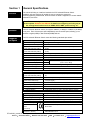
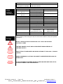
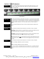
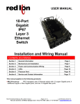
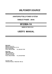
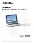
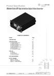
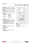
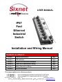
USER MANUAL IP67 Fast Ethernet Industrial Switch Installation and Wiring Manual Contents at a Glance: Section 1 General Specifications Page 3 Section 2 LED Indicators Page 5 Section 3 Mechanical Dimensions\Installation Page 6 Section 4 Power and Communication Wiring Page 7 Section 5 Mating Connections Wiring Page 8 Section 6 Service Information Page 9 This manual applies to the following products: ET-8ES-MIL-1 ET-8MS-MIL-1 ET-8xS-MIL_manual.r05 8-port unmanaged IP67 Ethernet switch with 8 10/100 ports 8-port managed IP67 Ethernet switch with 8 10/100 ports Page 1 of 9 Last Revised: 29-Apr-13 Sixnet 331 Ushers Road Ballston Lake, NY 12019 USA 1.518.877.5173 [email protected] SIXNET Protected Technology Policy - Sixnet protects your investment in Sixnet systems with longterm planned technology and our unique Protected Technology Policy. We will continue to support the specified capabilities of standard Sixnet products for at least five years (twenty years for Industrial Managed Switches). We plan each product improvement and new feature to be upward compatible with existing designs and installations. Our goals are to make each new software release bring new power to your Sixnet systems and have every existing feature, applications program and data file continue to work. We protect your investment even further with a liberal five-year trade-in policy. Exchange standard products for upgraded versions of the same product to take advantage of new features and performance improvements at any time for five years. A prorated trade-in allowance will be given for your existing equipment. Sixnet protects your long-term productivity with state-of-the-art planned technology and continued support. Sixnet Statement of Limited Warranty - Sixnet, manufacturer of Sixnet products, warrants to Buyer that products, except software, manufactured by Sixnet will be free from defects in material and workmanship. Sixnet's obligation under this warranty will be limited to repairing or replacing, at Sixnet's option, the defective parts within one year of the date of installation, or within 60 months of the date of shipment from the point of manufacture, whichever is sooner. Products may be returned by Buyer only after permission has been obtained from Sixnet. Buyer will prepay all freight charges to return any products to the repair facility designated by Sixnet. This limited warranty does not cover losses or damages which occur in shipment to or from Buyer or due to improper installation, maintenance, misuse, neglect or any cause other than ordinary commercial or industrial applications. In particular, Sixnet makes no warranties whatsoever with respect to implied warranties of merchantability or fitness for any particular purpose. All such warranties are hereby expressly disclaimed. No oral or written information or advice given by Sixnet or Sixnet’s representative shall create a warranty or in any way increase the scope of this warranty. This limited warranty is in lieu of all other warranties whether oral or written, expressed or implied. Sixnet's liability shall not exceed the price of the individual units, which are the basis of the claim. In no event shall Sixnet be liable for any loss of profits, loss of use of facilities or equipment, or other indirect, incidental or consequential damages. INSTALLATION AND HAZARDOUS AREA WARNINGS - These products should not be used to replace proper safety interlocking. No software-based device (or any other solid-state device) should ever be designed to be responsible for the maintenance of consequential equipment or personnel safety. In particular, Sixnet disclaims any responsibility for damages, either direct or consequential, that result from the use of this equipment in any application. All power, input and output (I/O) wiring must be in accordance with Class I, Division 2 wiring methods and in accordance with the authority having jurisdiction. FCC Statement - This equipment has been tested and found to comply with the limits for a Class B digital device, pursuant to Part 15 of the FCC Rules. These limits are designed to provide reasonable protection against harmful interference in a residential installation. This equipment generates, uses and can radiate radio frequency energy and, if not installed and used in accordance with the instructions, may cause harmful interference to radio communications. However, there is no guarantee that interference will not occur in a particular installation. If this equipment does cause harmful interference to radio or television reception, which can be determined by turning the equipment off and on, the user is encouraged to try to correct the interference by one or more of the following measures: Reorient or relocate the receiving antenna; Increase the separation between the equipment and receiver; Connect the equipment into an outlet on a circuit different from that to which the receiver is connected; Consult the dealer or an experienced radio/TV technician for help. Copyright & Trademarks - Copyright 2010 Sixnet, All Rights Reserved. Note: All information in this document is subject to change without notice. ET-8xS-MIL_manual.r05 Page 2 of 9 Last Revised: 29-Apr-13 Sixnet 331 Ushers Road Ballston Lake, NY 12019 USA 1.518.877.5173 [email protected] Section 1 Overview General Specifications This manual will help you install and maintain the IP67 Industrial Ethernet Switch. Installation of these switches will enable the user to manage the network by monitoring/gathering network data, allow for browser or telnet configuration, increase network performance, and more. Note: This manual only covers the installation and wiring of these switches. Refer to the separate Software User Manual for details on configuring and using any of the management functions such as SNMP, RSTP, IGMP, port mirroring, etc. Operation The IP67 Industrial Ethernet Switch can support 10BaseT (10 Mbps) or 100BaseT (100 Mbps) on all ports. Each of these ports will independently auto-sense the speed, allowing you to interface to regular(10Mb) or fast Ethernet(100Mb) devices. Standards and Specs The IP67 Industrial Ethernet Switch meets the following standards plus others: ET-8xS-MIL_manual.r05 General Ethernet switch type Ethernet protocols supported Ethernet connectors with olive-drab cadmium plating USB/RS232 connector with olive-drab cadmium plating Ethernet speed (10/100BaseTX) Ethernet MDI/MDIX Ethernet TD and RD polarity Ethernet isolation Latency for 10 Mbps ports Latency for 100 Mbps ports Full or half duplex operation MAC addresses supported Memory bandwidth 8 Fast Ethernet ports Managed or Unm anaged All IEEE 802.3 MIL-DTL-38999 Series III w/ 22D socket (female) contacts (9-35) MIL-DTL-38999 Series III w/ 22D socket (female) contacts (9-35) Auto-negotiation (10 or 100 Mbps) Auto-crossover Auto-polarity 1500 VRMS 1 minute 16us Typical less frame time 5us (Varies on load & settings) Yes, automatic on unmanaged, configurable on managed 2048 3.2 Gbps Power Power input receptacle with olive-drab cadmium plating Input voltage (all models) Input power (typical – with all ports linked and active) Reverse polarity protection Extended power protection Surge protection Transient protection Spike Protection Automatic power savings when ports are unused MIL-DTL-38999 Series III w/ pin (male) contacts (9-98) size 20 10-30 VDC (continuous) 3 W (unmanaged) 4 W (managed) Yes Exceeds MIL-STD-1275 100 volts for 1 second 15,000 watts peak 5,000 watts (10x for 10 uS) or 250 volts (50x for 100 uS) Environmental Operating temperature range Storage temperature range Humidity (non-condensing) Vibration, shock and freefall Electrical safety EMC emissions and immunity Hazardous locations (Class I, Division 2; Zone 2) Truly industrial design -40 to +75 °C (cold startup at -40 °C) -40 to +85 °C 5 to 95% RH (Conformal coating avaible by special order) MIL-STD-810F; IEC68-2-6, -27 and -32 UL508/CSA C22, EN61010-1 MIL-STD-461E; FCC part 15, ICES-003; EN55022, IEC61326-1 Page 3 of 9 ANSI / ISA 12.12.01, CSA C22.2/213; ATEX IEC60079-0, 15 Last Revised: 29-Apr-13 Sixnet 331 Ushers Road Ballston Lake, NY 12019 USA 1.518.877.5173 [email protected] Package protection Dimensions (L x W x H) (see diagram on next page) Weight (including caps) MIL Standard MIL-STD-810F; 501.4, I; 501.4, II MIL-STD-810F; 502.4, I; 501.4, II MIL-STD-810F; 507.4 MIL-STD-810F; 500.4, II MIL-STD-810F; 500.4, I MIL-STD-810F; 514 MIL-STD-810F; 516, I MIL-STD-810F; 516, V MIL-STD-810F; 509 MIL-STD-810F; 510, I MIL-STD-810F, Method 514.5 MIL-STD-810F, Method 512.4 MIL-STD-1275B Military Standards Compliance MIL-STD-461E-RE102 MIL-STD-461E-RS103 Safety Warnings IP67 dust, oil and water-tight 10.5 x 4 x 1.5” (267 x 102 x 38 mm) 2.20 lbs (1 Kg) Specification Description +70°C Transport/Storage High Temperature +65°C operating -20°C Transport/Storage Low Temperature -10°C operation 95% Humidity 9000 Feet Low pressure operating 15000 Feet Low pressure transportation 5-1000 Hz Vibration half sinus 40g 11msec Mechanical Shock Drop on table Handling Shock 5% salt for 48 hours Salt According to specs Sand and Dust Vibration while in transport Immersion into water; rain and wind resistance 100V for 1 second Surge Protection 15,000 watts peak Transient Voltage 250V (50 times for 100uS) Spike Protection 2MHz to 18GHz Radiated emissions (ground) 2MHz to 18GHz Radiated susceptibility Strictly abiding by these warnings will help ensure the safe installation, startup and operation of the switch. INSTALL THE SWITCH IN ACCORDANCE WITH ALL LOCAL AND NATIONAL ELECTRICAL CODES. LIGHTNING DANGER: DO NOT WORK ON EQUIPMENT DURING PERIODS OF LIGHTNING ACTIVITY. WARNING (EXPLOSION HAZARD) SUBSTITUTION OF COMPONENTS MAY IMPAIR SUITABILITY FOR CLASS 1, DIVISION 2 (ZONE 2). WARNING (EXPLOSION HAZARD) WHEN IN HAZARDOUS LOCATIONS, DISCONNECT POWER BEFORE REPLACING OR WIRING UNITS. WARNING (EXPLOSION HAZARD) DO NOT DISCONNECT EQUIPMENT UNLESS POWER HAS BEEN SWITCHED OFF OR THE AREA IS KNOWN TO BE NONHAZARDOUS. ET-8xS-MIL_manual.r05 Page 4 of 9 Last Revised: 29-Apr-13 Sixnet 331 Ushers Road Ballston Lake, NY 12019 USA 1.518.877.5173 [email protected] Section 2 Overview LED Indicators The IP67 Industrial Ethernet switches have communication LEDs for each port, an “OK” output LED, a status LED and power LEDs. Refer to the sample pictures below for the location of these LEDs. LED Locations Status LED The Status LED indicates the overall health of the switch. It is normally ON solid indicating that no internal CPU or software problems are detected. It will flash when loading firmware and briefly on power up or reset. Otherwise, if it is OFF or flashing for an extended period of time then a problem is detected. In this case, please contact your switch supplier for support. Power LEDs There is a power LED labeled as Power. It will be on solid when power is applied to the switch. LNK LED The port LEDs are multifunctional and indicate link confirmation, activity, and speed. Flashing = Indicates that there is a proper Ethernet connection (Link) between the port and another Ethernet device, and that there is communications activity. On Solid = Indicates that there is a proper Ethernet connection (Link) between the port and another Ethernet device, but no communications activity is detected. Off = Indicates that there is not a proper Ethernet connection (Link) between the port and another Ethernet device. Make sure the cable has been plugged securely into the ports at both ends. 100 LED The port LEDs are multifunctional and indicate link confirmation, activity, and speed. ON = A 100 Mbps (100BaseT) connection is detected. OFF = A 10 Mbps (10BaseT) connection is detected. OK LED This LED is not used in the standard model and will always be off. On special order units with dual power inputs, the OK LED will be lit when both the P1 and P2 pins have power applied. ET-8xS-MIL_manual.r05 Page 5 of 9 Last Revised: 29-Apr-13 Sixnet 331 Ushers Road Ballston Lake, NY 12019 USA 1.518.877.5173 [email protected] Section 3 Overview Mechanical Dimensions and Installation The IP67 Industrial Ethernet Switch can be mounted either on its edge or flat, as shown below. All LED’s are visible from either mounting position. NOTE: Mounting holes will accept a #12 size screw or smaller. 2.45" [62.2mm] 2.24" [56.9mm] Dia. 0.200" [5.1mm] 1.50" [38.1mm] 0.75" [19.1mm] 0.35" [8.9mm] 2.98" [75.7mm] 2.68" [68.1mm] 1.30" [33.0mm] with no cap or plug installed 9.98" [253.5mm] 10.48" [266.2mm] 9.98" [253.5mm] ET-8xS-MIL Pressure Vent Plug Power Input with plug installed (no backshell and wiring not shown) (typical) 2.91" [74.0mm] ET-8xS-MIL_manual.r05 Page 6 of 9 3.98" [101.1mm] Last Revised: 29-Apr-13 Sixnet 331 Ushers Road Ballston Lake, NY 12019 USA 1.518.877.5173 [email protected] 9.48" [240.8mm] RS232/USB Port (managed only) with cap installed (tether not shown) (typical) Section 4 Power and Communication Wiring The IP67 Industrial Switches can be powered from the same DC source that is used to power your other devices. 10 to 30 VDC needs to be applied between Pin A and Pin B as shown below. Overview NOTE: Any of the available mounting holes may be used for grounding and electrical bonding of the switch. * also allowed due to the auto-mdi/mdix-crossover + DC Supply No Connection No Connection - 5 A RX- B (TX-*) C 1 No Connection TX+ (RX+*) 5 4 1 6 3 2 USB-CNX (VBUS) USB-DM 4 5 6 RS232 and USB 3 RX+ (TX+*) 2 TX- (RX-*) USB-DP 4 5 6 1 GND 4 1 6 3 2 3 RS232-TD (output) 2 RS232-RD (input) Shell=A, Insert=98, Contacts=P, Keying=A Shell=A, Insert=35, Contacts=S, Keying=N Shell=A, Insert=35, Contacts=S, Keying=A Power Input Wiring All Models (ET-8xS-MIL) Ethernet Wiring All Models (ET-8xS-MIL) Console Port Wiring Managed Models (ET-8MS-MIL) ET-8xS-MIL_manual.r05 Page 7 of 9 Last Revised: 29-Apr-13 Sixnet 331 Ushers Road Ballston Lake, NY 12019 USA 1.518.877.5173 [email protected] Section 5 Mating Connections Wiring Overview The IP67 Industrial Switches meet or exceed all MIL-STD-38999 Series III for severe environmental applications. All connectors and their mating couplings have EMI shielding and ESD, moisture and corrosion resistance. All mating connectors will self-lock with one 360 degree turn of the coupling nut. Mating Connections The following mating plugs are required to interface with the switch: Ethernet Plug D38999/26WA35PN (w/ pin contacts and Normal keying) Power Plug D38999/26WA98SA (w/ socket contacts and “A" keying) USB/RS232 Plug D38999/26WA35PA (w/ pin contacts and “A” keying) Cable Distance Typical Plug The maximum cable length for 10/100BaseT is typically 100 meters (328 ft.). ET-8xS-MIL_manual.r05 Page 8 of 9 Last Revised: 29-Apr-13 Sixnet 331 Ushers Road Ballston Lake, NY 12019 USA 1.518.877.5173 [email protected] Section 6 Service Information Service Information We sincerely hope that you never experience a problem with any Sixnet product. If you do need service, call Sixnet at (518) 877-5173 and ask for Technical Support. A trained specialist will help you to quickly determine the source of the problem. Many problems are easily resolved with a single phone call. If it is necessary to return a unit to us, an RMA (Return Material Authorization) number will be given to you. Sixnet tracks the flow of returned material with our RMA system to ens ure speedy service. You must include this RMA number on the outside of the box so that your return can be processed immediately. The applications engineer you are speaking with will fill out an RMA request for you. If the unit has a serial number, we will not need detailed financial information. Otherwise, be sure to have your original purchase order number and date purchased available. We suggest that you give us a repair purchase order number in case the repair is not covered under our warranty. You will not be billed if the repair is covered under warranty. Please supply us with as many details about the problem as you can. The information you supply will be written on the RMA form and supplied to the repair department before your unit arrives. This helps us to provide you with the best service, in the fastest manner. Normally, repairs are completed in two days. Sometimes difficult problems take a little longer to solve. If you need a quicker turnaround, ship the unit to us by air freight. We give priority service to equipment that arrives by overnight delivery. Many repairs received by mid-morning (typical overnight delivery) can be finished the same day and returned immediately. We apologize for any inconvenience that the need for repair may cause you. We hope that our rapid service meets your needs. If you have any suggestions to help us improve our service, please give us a call. We appreciate your ideas and will respond to them. For Your Convenience: Please fill in the following and keep this manual with your Sixnet system for future reference: Serial #:__________________ Date Purchased: ___________________ Purchased From:______________________________________________ Product Support To obtain support for Sixnet products: Latest product info: http://www.sixnet.com Phone: 1 (518) 877-5173 Fax: 1 (518) 877-8346 E-mail: [email protected] Mailing address: Sixnet, 331 Ushers Road, Ballston Lake, NY 12019 ET-8xS-MIL_manual.r05 Page 9 of 9 Last Revised: 29-Apr-13 Sixnet 331 Ushers Road Ballston Lake, NY 12019 USA 1.518.877.5173 [email protected]