1
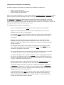
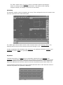
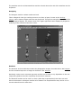
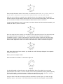
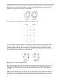
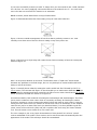
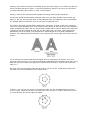
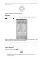
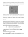
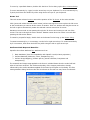
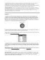
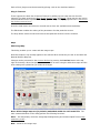
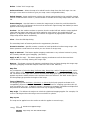
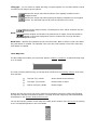
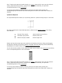
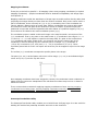
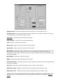
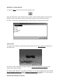
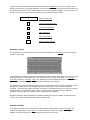
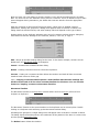
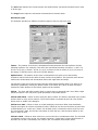
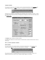
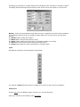
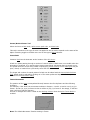
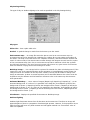
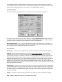
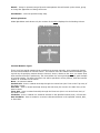
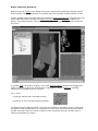
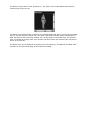
2.0
Introduction and Basic User Manual
Progam Modules
There are three main modules, an Animator, a Designer, and a Renderer.
The Animator module is where animations are staged and Actors perform in front of the camera.
The animations are rehearsed and previewed in wireframe or shaded mode in near real time. The
other modules are loaded from the Animator and remain active until explicitly closed.
The Designer is used to design and build costumes for Actors, it uses a conventional triangular
faceted 3D representation with facets attached to a network of vertices. Like the Animator the
user is given three view windows in which a wireframe for the model is built up.
The Renderer is used by both the Animator and Designer and will continue to execute in the
background if activity continues in the other modules.
Other External Libraries are available that add functionality and if suitable program development
tools are available it is possible to build additional libraries. Textures, image processors, and
animation effects are examples of external libraries.
The Approach to Animation and Modelling
The Main concept of the program is to observe the standard conventions of:
•
•
•
Click on an item to select it.
Double click for extended information
Click and drag to move the item.
All the user actions take place in a cubic volume called the Working-Volume. A 3D Cursor may be
placed anywhere inside the Working-Volume by moving it in one or more of the view windows.
The Animator and Designer modules have two main user interface components, Tools and
Actions. Tools are appropriate for repeated use and actions are usually applied one at a time.
When a tool is activated it stays active until another tool is selected. In the Designer, actions are
normally prohibited unless the default tool is in use.
The language of the Animation and Modelling
We use a "Triangular Faceted" model of the objects that are to be animated.
Objects can be anything you like, a car, a plane, a spaceship, a cup, a box of
breakfast cereal, a dog or a human figure.
The triangular faces are joined together to form the surface of the models and the
more numerous the triangles, the more realistic the representation of the object
the model is.
Deciding how many triangles to use in the model is not an exact science. The
triangular faces can be given additional attributes such as color and texture to
make the models look realistic. They can even have a picture or another animation
painted onto them.
The triangular facets (faces of the model) are positioned using a vertex at each
corner. Each triangular face is surrounded by three edges. The edges make up a
"wireframe" description of the model.
You use the mouse to move the vertices of the model in 3D space and thus change
the shape of the model. There are many tools and actions to help you.
The action takes place over a number of 'frames', a movie usually plays 24 frames
per second, conventional cartoon animation usually shows 12 different frames per
second. A reasonable animation will consist of about 60 frames. But it could stretch
to nearly 1000 frames for just one shot!
Models are built inside a cubic region of space called the "Working-Volume". The
size and position of the "Working-Volume" is easily changed.
A Keyframer specifies costume, movement, orientation and scale in "Keyframes".
Animations are rehearsed in "wireframe" in the Animation module before the
drawing is rendered in full color, frame by frame. Each frame may be compressed
together into an FLI or FLC animation file.
In an animation the term "Actor" is used to describe each directable element. An
Actor can be a "Star" which performs in front of the camera, the Camera from
which the animation is viewed, one of a number of lights, or a path along which
smooth and accelerated motion is possible.
The "Star" Actors wear a "Costume" which is an model created in the Designer.
Actors can change costume during the animation. (This allows model morphing changes of shape, for example. a fish can turn into a bird).
Animating
The Animator module is where animations are set up. Three orthogonal views and a camera view
show the world where the action takes place.
The visible region of the world is inside a cubic volume known as the Working-Volume. The
Working-Volume may be moved through space and changed in size.
A major component of the Animator is the Keyframer, the keyframer shows the timelines and
keyframes for all the Actors in a spreadsheet format.
Keyframer
To direct the activity of an Actor during an animation requires the use of timelines and
keyframes. The Keyframer is a module where the timelines and keyframes of all Actors can be
viewed and edited in one display. Normally timelines and keyframes are created implicitly as
Actors are added and the tools are used to move then into position and tell them what to do.
In the keyframer window time runs in the horizontal direction and for each Actor the extent of
timelines and position of keyframes is displayed.
The timelines are the red horizontal lines and the colored dots at the end of the timelines are the
keyframes.
Designing
The Designer module is where models are built.
Three orthogonal views give working access to a volume of space, known as the WorkingVolume, where Vertices edges and faces may be placed. This gives a triangular faceted model for
real or imagined objects. The Camera View in the upper right hand corner displays a perspective
rendering of the contents of the three views.
Renderer
The Renderer is the module that creates the photographic images of models built in the Designer
and the animated sequence of images as directed in the Animator.
Rendering is quite a time consuming process and the time it takes is very dependent on the size
image being produced and the complexity of the Actor's costumes.
The Renderer module can be used in a mode (called the Script Renderer) that does not need
either the Animator or Designer modules to be loaded. The Script Renderer may also be run on
several others PCs at the same time.
3D Cursor
The 3D Cursor is used indicate an exact position in 3D space. The intersection of any two 3D
cursors in the Working-Volume Top, Front, or Side views indicates an exact position in 3D space.
The 3D Cursor is positioned with the Windows' Mouse Cursor.
The 3D Cursor can take the form of either a Cross Hair or a Cross Wire. Note you can toggle
between these two 3D Cursors with the F9 Key.
Cross Hair 3D Cursor
Cross Wire 3D Cursor
Moving and Sizing the Working-Volume
The Working-Volume may be moved through space and changed in size. To move it use the Hand
tool and to change its size use the Zoom tool. Both these tool have keyboard accelerator key
equivalents.
Pan by pressing the space bar and then click and drag.
Zoom In by holding the Space bar and Ctrl keys simultaneously then click to re-center window
box and zoom. Click and drag to define region to be viewed in full window.
Zoom Out by holding the Space bar and Alt keys simultaneously then click to Zoom out and recenter.
Double-click on the Zoom Tool to enclose all parts of the model and its vertices in the
WindowBox.
Designing with - Vertices, Edges, and Faces
All Models are described by the arrangement of it's Vertices, Edges, and Faces.
It is the placement of the Vertices and arrangement of Edges that give a model it's shape and
form. How the Faces are painted and textured gives a model it's realistic appearance.
Face and Edge Creation
The central theme of the triangle-based modelling system used by the designer module is
faceting.
The Unfilled Outline on the left would not render since it is not composed of faces (triangles) and
would be considered a hole. The Filled Outline on the right would render as a surface.
There are two ways to facet (make triangular faces so that they fill) an outline ...
Auto Filling
Using the Fill Outline or Fill to Cursor actions
Strutting
Using the Draw Tool
Draw Tool / 3D Plot Tool
This tool plots a curve (composed of a set of vertices and edges) in the Working-Volume view
windows.
Place the first vertex of the curve by clicking once in one of the Working-Volume view windows.
Click and drag the 3D Cursor (a rubber band line is drawn between the last vertex inserted and
the 3D Cursor while the left mouse button is held down) to the desired position of the next vertex
of the curve. Release the left mouse button to create the next vertex of the curve. If you just
click the left mouse button, a vertex is added at that point.
If the "Shift" key is held down while dragging the mouse then the extending line is constrained to
45° angles. The active window will scroll as the mouse approaches the edge of the window.
If the "Ctrl key" is held down then no new vertices are created. This enables positioning of the 3D
Cursor in two windows before re-commencing drawing.
If the "Alt" key is held down then when the mouse is clicked a "New edge" is started. The "New
edge" is not attached to any previous vertex on the curve.
The DrawTool can also be used to draw edges between existing vertices by clicking exactly on top
of the desired vertex.
To enable the 3D Plot Tool, double-click on the DrawTool.
Strutting
This strange term describes the process of faceting a curve using the Draw Tool or 3D Plot Tool.
To try this, draw a curve like the one shown below using the DrawTool.
Draw an edge between vertex 6 and vertex 1 to close the curve. Make sure you click exactly on
top of vertex 1, otherwise a new vertex will be added and the curve will not be closed.
With the curve in Figure 1 created, have a good look at it in the Camera View. The OpenGL
Shaded Camera View will display nothing since the curve must be faceted (filled) first. Note that
you can see the wireframe curve if the OpenGL Saded Camera View is turned off.
Create an edge between vertex 2 and vertex 6 as shown below. With the DrawTool enabled, click
exactly on vertex 2, then on vertex 6
Once the edge has been created, you should see (lower right hand corner of the status bar) that
the number of faces increases by one -- you have created a face! The face in question is
composed of vertex 1, vertex 2 and vertex 6. Take a look at these vertices to verify this (that
they form a triangle). Now we can proceed to create two more edges to form all the necessary
faces. Create edges from vertex 3 to vertex 6 and vertex 4 to vertex 6 as shown in Figure 3.
After these edges have been created, you should see a solid 3D shape displayed in the OpenGL
Shaded Camera View.
Now try a more complex outline.
Draw an outline of the letter 'C' as shown in Figure 4.
You should be able to close the curve with the DrawTool alone. The outline is a very rough
approximation of the letter 'C'. This is entirely due to some questionable drawing skills! Hopefully
you should be able to produce a better C. It does not matter if your outline has more vertices
than the one above, you should be able to follow the instructions anyway.
Using the Draw Tool and the strutting technique described to create Figure 3, create an edge
between vertex 1 and vertex 3. This will create a face (check for the triangle). Create another
edge between vertices 3 and 15. Another face will be created (check again). Then create an edge
between vertices 15 and 4. Yet another face will be added. Hopefully you should also see why
this technique has been called "strutting". Continue creating edges and faces until you have
something like that shown in Figures 5 and 6 below.
The sequence for creating all the vital edges in the case above is :
Edge
Edge
3
to
15
15
to
4
4
to
14
14
to
5
5
to
13
13
to
6
6
to
12
12
to
7
12
to
8
8
to
11
11
to
9
The edge marked in red is important. It represents a change in rhythm. You should be able to
see the pattern in standard strutting : a to b, b to c, c to d. However, the marked red edge
violates this pattern. This is often necessary to avoid having long thin faces. Note the angle
between edges 12 to 11 and 12 to 7 on the left is much greater than 90%. The best choice on
the right keeps the angles close to or less than 90%.
RULE 1: Always avoid long thin faces.
This is not just a matter of style. The Renderer will usually cope with long thin faces, but it will
increase the rendering time. Having long thin faces often makes the model more difficult to
manipulate. So, although there is no real prohibition against long thin faces, they should be
avoided.
While you where faceting your 'C' outline, you may have felt the need to change the rhythm of
the strutting to avoid violating rule 1. This should be quite natural. Just keep in your mind the
objective of rule 1 and, after a little practice, faceting outlines should become second nature.
If you have successfully created you solid 'C' shape, then you can extrude it into a solid character
for a 3D font. You can try applying colors and textures to the model for the 'C'. You could even
save it for later use as an actor's costume in an animation.
RULE 2: Never, never have faces on top of each other.
Figure 10 demonstrates what four faces sitting on top of each other looks like.
Figure 11 shows a similar arrangement of four faces that is perfectly correct to use. Look
carefully to see that none of the four faces is sitting on top of any other one.
Figure 12 shows how a single edge will create the two faces necessary to facet the rectangular
outline of Figure 10.
Rule 2 is not quite a absolute as it sounds. The Renderer does a "depth sort" which should
eliminate any problems in the final image, but it is very bad style to create models with faces
sitting on top of each other.
Figure 11 actually shows what the rectangular outline would look like if faceted by the Fill to
Cursor action. The contrast with Figure 12 should enable you to make some distinction between
faces created by strutting and faces created by the Fill to Cursor action. Note that the Fill Outline
action would have faceted the outline as in Figure 12.
As mentioned before, both methods of faceting have advantages and disadvantages. The Fill to
Cursor action creates an extra vertex which is not strictly necessary for faceting the outline.
Therefore, strutting is a more economical method (it does not need an extra vertex). However,
having an extra vertex which is a member of all the faces can be an advantage. In the simplest
case this can just be an Auto-Filled circle (as described above). It is then possible to grab the
center vertex of the solid circle (disk) and pull it up above the circle using the Vertex Selector
Tool. This will create a cone similar to an ice-cream cone.
The cone example is just a very basic demonstration of how powerful it is to have 'control'
vertices embedded in the model. These vertices can be moved around to dramatically alter the
appearance of the model. This technique should be remembered.
Another, not so obvious economic advantage of the structure in Figure 12, is that it has just two
faces. The filled structure in Figure 11 (the Auto-Filled one) has four. Of course, the less faces
you have the better (less memory is used, renders faster).
Finally, in what is the most advanced example of faceting, holes will be considered.
A brief note should be made about triangular holes. You may have already tried to create the
letter 'A', but you may have got stuck on the triangular hole. This appears to be a real problem.
If a triangle defines a solid face, how can you have a triangular hole ?
The solution is simple, and like many techniques in animation, a cheat. Create your triangular
'hole' as a normal triangular face. Then select the two vertices at the end of one of the triangle's
edges. Subdivide the edge. Now you should have a shape with 4 vertices. Remove the edge that
'crosses' the would-be triangular hole and you will really have a true hole. This is because by
Subdividing one of the edges, you changed the 3 sided triangle into a 4 sided quadrilateral.
However, the quadrilateral was still solid, so you removed the crucial edge and turned it into an
outline.
You should have an outline that looks triangular but it is composed of 4 vertices, so it is not
triangular and not a face. If you did not completely understand this explanation then don't worry.
After you have had a little more experience it should become clearer. (Just try and create the
letter 'A' !)
But once you have the outline (hole and all) how do you turn it into a solid shape ready to be
extruded? This is demonstrated by the outline below
In Figure 7 you can see two circles, one inside the other. For this example suppose the inner
circle is a hole. Create the circles for yourself (the outer one has 10 vertices, the inner one has
5). Look carefully at how the edges are added.
Try this technique on your copy of the circles. Once you have done that, adding the edges shown
below should be easy.
Check that all the faces have been added properly.
Build Primitives
The Build Primitives dialog enables generation of Cone, Cube, Cylinder, Disk, Polygon, Rectangle, GEO
Sphere, Latitude Sphere, Tube and Torus primitives by specified dimensions.
Choose the desired primitive, type in the dimensions, and press the Make button. The Build Primitives dialog is
modeless so it can be left up if a number of primitives are to be inserted.
You can also interactively generate a primitive by choosing the desired Primitive's tab page and dragging out a
bounding box in any of the Working-Volume TOP, FRONT, or SIDE views. The specified primitive will fill the
space of the bounding box. Note that the Auto checkbox must be checked to interactively draw primitives.
Selection Marquee Tool
Drag select or deselect a set of vertices.
•
Holding down the Shift Key while dragging changes the selection marquee from a
rectangle to a Lasso.
•
•
Holding down the Ctrl Key while dragging changes the selection marquee from a rectangle
to a circle.
Double-click on the Selection Marquee Tool to toggle to the Deselection marquee.
Extrude
Extrude selected vertices and edges to make a 3D shape.
After executing the Extrude action, the tool reverts to the Move Tool. Drag the newly duplicated
and selected vertices to the desired length of the extrusion.
Note that you can also put a thickness on some models by extruding and then scaling to the
desired thickness.
To extrude selected vertices along a defined path, use the Actions > Extrude Special > Along
action.
Lathe
Make rotationally symmetric shapes as on a lathe.
The action extrudes the selected vertices while rotating them around an axis. The axis runs at
right angles to the active window.
Two parameters must be specified in the Lathe dialog.
1) The number of sections (smoothness of the lathe)
2) The angle to spin (usually 360 degrees, a maximum of one revolution).
Example: Use the Lathe action to create a wine-glass. In the Front view window, draw the
profile of half of a wine glass. Use the Pen Tool or 3D Plot Tool to draw the outline.
When you are satisfied with the outline, position the 3D cursor in the Top view window. The Top
window will now be the active one and is highlighted with a yellow border. The axis of spin of the
lathe will therefore be at right angles to the Top window, that is, up/down or in the direction of
the Z axis.
Make sure that all the vertices of the outline are selected, then execute the Lathe action. If you
do not get anything that resembles a wine glass, Undo it and try again.
If you move the 3D Cursor in any window other than the Top window, you will deactivate the Top
window and the Lathe action will produce a structure which is the result of spinning around an
axis perpendicular to another window. The result is a total mess. When done properly, however,
a good model for a wine glass can be produced in seconds.
The Lathe action is tremendously powerful for building parts of models with a high degree of
rotational symmetry. Examples of this are: chess pieces, aircraft engines, pens, pencils, glasses,
lamp shades, space rockets, etc.
Scale Tool
Scales selected vertices about the position of the 3D cursor.
Up/down left/right and back/front scaling factors can be adjusted with the help of modifier keys.
Click (press and release the left mouse button) without moving the mouse to place the 3D cursor
at the coordinates you want to be the center of scaling. Click in a window and drag the mouse to
the left or right to scale the selected vertices about the 3D cursor. Scaling starts when the mouse
is moved after pressing the left mouse button.
Differential scaling can be applied by using the following modifier keys.
Shift
expand in the front-to-back (Y coordinate) direction only
Ctrl
expand in the up-down (Z coordinate) direction only
Alt
expand in the left to right (X coordinate) direction only
To scale selected vertices by a numeric factor, double-click to bring up the Scale dialog.
Move Tool
This tool moves the selected Vertices to a new location.
Click anywhere in the view windows and a purple rectangle encompassing the selected vertices is
displayed. Continue holding down the mouse button and drag the purple rectangle to the spot to
which you want the vertices moved.
To move by a specified distance, double click the Move Tool to bring up the Move Vertices dialog.
To move interactively by 1 pixel, use the arrow keys on your keyboard. To move interactively by
5 pixels, hold down the SHIFT key while using the arrow keys on your keyboard.
Rotate Tool
This tool rotates selected vertices around the position of the 3D Cursor in the active window.
Click (press and release the left mouse button) without moving the mouse to place the 3D cursor
at the coordinates you want to be the center of rotation. Click in a window and drag the mouse to
the left or right to interactively rotate the selected vertices around the 3D cursor.
Rotation occurs around an axis passing through the 3D Cursor and running in and out of the
screen. The axis is through the active window. Rotation starts when the mouse is moved after
pressing the left mouse button.
To rotate by a specified angle, double-click on the Rotate Tool to bring up the Rotate dialog.
To rotate interactively by 1° increments, use the left or right arrow keys. To rotate interactively
by 5° increments, hold down the SHIFT key while using the left or right arrow keys.
Attributes Mesh Maps and Materials...
Specifies the surface attribues face attributes such as:
1. Basic Attributes (Used for compatibiliyt with OpenFX 1 and/or basic properties.)
2. Surface Materials (Shininess, colour, transparency etc.)
3. Surface Image Mapping, (Surface picture, pseudo reflection, bumpiness and
transparency.)
The materials and image maps applied to the faces in a Model dictate how the model will look
when it has been rendered. The realism and quality of the images produced are heavily
influenced by the surface attributes applied to the faces by the option in this dialog. The face
setting attribute dialog has three tabs and it indicates in the title how may faces are selected:
Surface Image mapping not only requires the specification of the picture files, it also requires the
specification of a set of mapping coordinates that cover the surface (a good analogy is how the
latitiude/longitude coordinates map the surface of the spherical earth.)
Attributes are applied to selected faces in the model. A face is selected if all vertices at its corners
are selected. The attributes dialog is modal and all the tools, actions and menu commands are
active while it is visible.
Basic Attributes
This tab is used for setting the most basic of surface attributes that can be appled to selected
faces.
Color Swatch - Selects and sets the color of the selected faces.
Smoothing - Specifies Phong Smoothing for selected faces
Note: that these attributes are not used if a materal or image map has also been applied to the
same selected faces. If some or the selected faces have a material or an image map applied a
warning icon and message are displayed.
Surface Materials
Applies material properties and algorithmic textures to selected faces.
Changes can be previewed in the Camera Window by pressing the Preview button at the bottom
of the dialog. The OpenGL previewer when used in appropriate processors will also display the
materials.
The Set button assigns a material to the selected faces.
The Edit button calls up the edit material buttons.
The Drop button removes any material that is applied to the selected faces.
The Move button allows you to move the Material Axis (which is used to position the material's
appearance relative to the object.) This feature is described under the heading of materials.
Edit Material
A maximum of 64 materials can be applied to every model and each one is defined using the
dialog below. (A material is applied to the selected vertices using the "Mesh Map and Materials"
menu command.)
All materials are described through the Material Settings dialog.
The Basic Controls in the Dialog
New - Create a new material with basic default properties.
Delete - Delete this material.
Select / Rename - Use the dropdown list box to select the material to be edited or to change
the name of the material.
Copy - Copy the properties of an other material to this one. A pop-up dialog will allow you to
select the material to be copied.
Close - Close the materials dialog.
Preview - Use the scanline renderer to generate a preview of the 3D view of the object. The
GPU based OpenGL 3D view will automatically update to illustrate the current settings. (With the
exception of any plugin textures wich are only displayed in the scanline renderer or in the full
renderer.
Colour - Click on the colour swatch to select the basic diffuse colour for the material.
Second Colour - Specifies the secondary color used by many of the material's textures.
Check Boxes and Settings
Smoothing - Specifies Phong Smoothing for selected faces.
Shiny Hotspots - Assign specular highlights to the material, to simulate the appearance of
shinyness/glossiness.
Glass Edge Effect - Give any glass edges the illusion of being slightly darkened. This effect is
only applicable to the scanline renderer.
Glossiness - Adjusts the shininess (size of Shiny Hotspot) of the faces if the Shiny Hotspots
check box is checked. The Shiny Hotspot is largest at low values and smallest at high values.
Metals are shiny but chrome has a different shininess than aluminum. Shininess is simulated by
what is known as a specular highlight. Basically, the more shiny a surface the smaller the
specular highlight. For example, plastic material has a less shiny appearance than tin, so a plastic
bottle will have a larger specular highlight than a tin can.
Reflectivity - The selected faces can be made to have a partially mirrored surface showing a
reflection of the Sky or Ground during an animation. The degree of reflection is governed by
slider setting. A value of 8 means a 50/50 mixture of reflected image and surface color.
The Reflectivity slider also specifies the level of reflectivity for other objects in addition to the Sky
and Ground if Ray Trace reflections are enabled in the Trace Tab page of the Render Settings
dialog.
Transparency - The Glass texture uses this parameter to set it's transparency. A value of 0 is
totally opaque while a value of 15 is totally transparent. Any totally transparent faces will be
completely invisible. The Glass Edge Effect darkens the glass along its profile if turned on.
The transparency setting has a special relationship to the Glossiness flag. If the flag is On the
transparency decreases near the edges of objects and they show specular highlights
superimposed on the Glass surface. This effect is very often seen in thick glass objects especially
where they have some curved surfaces. (This does NOT apply to the GPU renderer.)
Texture Parameter - Many of the internal & external textures require a parameter to specify
some parameter or the other. This slider privides a way to change such parameters. For example
the rough or bumpy internal texture requires a value for how rough it might be; in such an
instance the roughness is set via this slider.
Textures
In addition to the basic material settings above, an algorithmic texture can be applied to the
surface to give it a richer and more complex appearance. There are a small number of built-in
textures, such as granite, marble, and wood. And a much larger range of plug-in textures that
allow for a much wider range of texture appearances to be simulated. Procedural textures are
algorithms that mathematically define the appearance of a shape or surface texture. Procedural
textures act on volumes where image maps act on surfaces.
Blend texture
To use one of the built in textures - click in the "Internal textures" check box and the "Choose
Internal Texture" button to select the texture from a pop-up list.
Select either the Internal check box or the Plug In Texture check box to choose the Texture Type
to apply from a list of Internal Textures:
The Parameter sliders adjusts the parameters the Clouds, Bumpy, Aztec, Wrinkled, Agate, and
Dents textures. For example, bumpy textures such as Bumpy, Aztec, Wrinkled, Agate, and Dents
use this parameter to set the height of the bumps. The larger the slider value the higher/deeper
the bumps.
Move Material Origin - This button is used to adjust the origin and orientation of this material.
It will activate the Move Material Origin mode and display the Snap Palette.
Plug-In Textures - These extend the range of textures that can be applied to a surface. Up to
four textures can be layered within a single material. So for example, a rough - normal bending texture can be used along side a surface colouring texture like a marble. To use the plugin
textures click on the Plugin Textures check box.
Each of the 4 plugins must be activated by placing a tick in the checkbox beside it.
Plug-in Textures
These augment the basic list of Internal Textures by adding up to 4 extra textures for each
material. Five basic textures are Bozo, Brick, Dimple, Dots, and Ripple. These textures are held in
external libraries and it is possible to develop your own by creating appropriate DLL's. See the full
list of other textures here...
Press the Load button and select an external texture from the available textures/shaders.
The Edit button enables the editing of the parameters for that particular texture.
The Drop button clears the slot and removes that particular texture from the material.
Maps
Edit Image Map
This dialog enables you to create and edit image maps.
Note that maps are not actually applied to the selected faces unless they are Set in the Mesh and
Material Dialog's Map Tab.
Changes can be previewed in the Camera Window by pressing the Preview button at the top
right of the dialog. When the OpenGL camera window is active using the GPU these maps and the
other settings are updated as you make the changes.
Note: All the image maps are (by default) embedded within the .OFX model file. The
main command buttons in the dialog perform the following functions:
Move - This temporarily closes the Image Map Settings dialog and suitches OpenFX into image
positioning mode...
New - Create a new image map.
Delete - Delete "this" image map.
Select and Name - Selete the map to be edited from the drop-down list of all maps. You can
also type a new name in the box to give your map a more recognisable idetity.
Embed Images - Some models may not have the image maps included in the model file (mainly
models constructed with Version 1) Use this button to include all the image maps within this .MFX
file.
Extract Images - Use this button to extract the image maps (so that they could be edited for
example) into a file. The filename is the one from where the original image was loaded (its name
appears in the image list below.
Preview - Use the scanline renderer to preview how the model will look with the image applied.
(Note that this image map must have been applied to some faces in the model before this
appears.) In OpenFX 2 if the OpenGL View window is supported by appropriate hardware - the
image maps will be drawn realistically.
Close - Close the Edit Map dialog.
The secondary batch of buttons performs the suppimentary functions:
Preset for Surface - OpenFX contains a number of small predefined surface image maps - this
button presents a small menu from which you can choose an image map.
Apply to Selected - This button applies mapping coordinates to any selected vertices by using
the currently selected type of mapping. (See below).
Apply to All (for map) - This button applies mapping coordinates to all the faces and their
vertices that are currently showing this image map.
Remove - This button removes all mapping coordinates from any faces showing this image map.
(Removing mapping coordinates helps to reduce the size of the .MFX file.)
Map files
Any combination of a Surface Map, Reflection Map, Bump Map, and/or Transparency Map can be
used to define a full Image Map. The Maps may be still images or an animated .AVI type movie
file. The sliders to the right of the Surface and Reflection Map types specify the percentage of the
applied map that is visible relative to the surfaces colors and textures. The slider to the right of
the Bump Map type specifies the height of the bump.
Types of Mapping
The Mapping Type can be Planar, Cylindrical, or Spherical the fourth grayed-out button is for
compatibility purposes with OpenFX 1 and it will show a "Fixed-To" mapping type when this old
type of mapping is in use. In OpenFX version 2 all maps use mapping-coordinates and OpenFX 2
will perform an automatic conversion to this new way of applying mapping.
Map angle - This defines the angle over which the cylindirical mapping applies. For example, if it
is set to 180 degrees then the image covers one half of a cylinder.
Map Layout
The map can be applied over the surface to which it applies in several ways;
Tiling
Specifies that the face's color will show through on faces or parts of faces
outside the mapped image.
Specifies that the map is repeated so that all selected faces are painted with the
image map. See also Mosaic Maps.
Tiling type - you can choose to repaat the tiling in regular repeats or in a mosaic fashion so that
no seams in the image map are aparent.
Renders the image map with the effects of the lighting conditions on the
mapped surface.
Shading
Renders the image map while ignoring the lighting conditions on the mapped
surface. An unshaded map can be used to represent a TV screen.
Renders image maps normally. The background color will be rendered onto the
selected faces.
Decal
Enables insignia and decals to be painted onto an object. Faces that would be
painted in the map's background color are rendered as if no map had been
applied to them.
Decal Color - Specifies the transparent color used for Decals. Black or white is used if the Index
Key radio button is enabled. The specified color in the Key Color swatch is used if the Color Key
radio button is enabled.
Move Map Axes
The Move Map Axes enable you to precisely position a Planar, Cylindrical, or Spherical image map
on a 3D model.
The area enclosed (shaded Gray) by the Map Axes is defined in the Working-Volume views using
three handles.
Top Left (T/L) Handle
Anchor handle moves all axes
Top Right (T/R) Handle
Resizes width or radius
Bottom Left (B/L) Handle
Resizes length
Position and size the image map on the model in the Working-Volume by clicking and dragging
the Map Axes handles to the desired position. The Map Axes and image map will simultaneously
be displayed in the OpenGL Shaded Camera View.
You can also set the position of each map axis handle at the location of the 3D Cursor by pressing
on the corresponding button in the Lock Palette.
Hint: To place each map axis handle directly on a vertex, place the 3D cursor near the selected
vertex, press the F2 Key (Actions > Snap Cursor > To Closest Selected), the press the
corresponding button in the Lock Palette.
To lock the map handles to specific vertices, press the Lock button after pressing the
corresponding map axis handle. Note that locking will not work if more than three vertices are
selected.
Cylindrical Map Axes
The Cylindrical Map Axes enable you to precisely position a cylindrical image map on a 3D model.
The area enclosed by the Cylindrical Map Axes is defined in the Working-Volume views using
three handles.
Top Left (T/L) Handle
Anchor handle moves all axes
Top Right (T/R) Handle
Resizes radius axis
Bottom Left (B/L) Handle
Resizes length axis
Position and size the image map on the model in the Working-Volume by clicking and dragging
the Map Axes handles to the desired position. The Map Axes and image map will simultaneously
be displayed (as a planar map) in the OpenGL Shaded Camera View.
You can also set the position of each map axis handle at the location of the 3D Cursor by pressing
on the corresponding button in the Lock Palette.
Hint: To place each map axis handle directly on a vertex, place the 3D cursor near the selected
vertex, press the F2 Key (Actions > Snap Cursor > To Closest Selected), the press the
corresponding button in the Lock Palette.
To lock the map handles to specific vertices, press the Lock button after pressing the
corresponding map axis handle. Note that locking will not work if more than three vertices are
selected.
Mapping Coordinates
These play a vital role in OpenFX 2. All mapping is done using mapping coordinates (or implied
mapping coordinates). (Implied coordinates allow for backward compatibility with image maps
from OpenFX 1).
Mapping coordinates enable the attachment of image maps to model surfaces directly rather than
projecting the images directly on them when the model is rendered. Each vertex carries with it a
pair of coordinates, known variously as (u,v) or (s,t) or something else. These coordinats are
used to address a pisition within an image map. Sticking coordinates onto vertices allow maps
and textures to move with parts of the model as it moves or morphs. It permits maps to be
positioned in ways that would be impossible with either Planar or Cylindrical mapping. The (u,v)
do not have to be related to the world coordinate system (x,y,z)
The coordinate system is scaled so that each image in the map fits inside a unit square of the
(u,v) coordinates. That is; any point on the surface with (u,v) coordinate in the range 0.0 < u <
1.0 and 0.0 < v < 1.0 will equate to a pixel in the image map. If a point on the surface has a
(u,v) coordinate with either greater that 1.0 or less than 0.0 then the integer part of the
coordinate is removed leaving only the fractional part for example a (u,v) coordinate of
(1.5,10.35) is reduced to (0.5, 0.35) and (-1.3, - 5.0) is equivalent to (0.3, 0.0). These
equivalent points both lie in the unit square and thus they can be mapped to a pixel in the image
map.
The surface (u,v) coordinates correspond to specific places in the image.
The point (0.0, 0.0) is at the Bottom Left corner of the image, (1.0, 0.0) is at the Bottom Right
corner and (0.0,1.0) is at the Top left corner.
Once mapping coordinates have been assigned to vertices, the coordinates remain unaltered, no
matter how the vertices are manipulated. This will allow the surface map to move or distort to
follow the vertices.
There are three basic methods for applying mapping coordinates to faces: deriving mapping
coordinates from existing maps, entering mapping coordinates manually, and automatically
generating mapping coordinates while using tools and actions
Postscript Text Builder Utility
The Postscript Text Builder Utility enables you to build 3D text for flying logos. It is also useful for
building 3D models from postscript character sets such as the Carta font.
Shape Preview - Previews the shape of the font character in the Font Preview box.
Profile Preview - Previews the profile of the font character in the Font Preview box. The profile
is manipulated using the Width and Bevel sliders.
Hold Point - Defines the axis of rotation for the font.
Choose button - Click to select a new Postscript font.
Text - Enter the characters for the logo.
Bevel Front - Adds a bevel to the front of the font letters.
Bevel Back - Adds a bevel to the back of the font letters.
Bevel Angle - Defines the angle of the bevel. The bevel will fail if the specified angle is too sharp
and causes an intersection. If bevel fails, reduce the angle and/or depth. The failure point
depends on the type of font. Narrow thin fonts are likely candidates and the bevel should be kept
as small as possible.
Bevel Depth - Defines the width of the bevel.
Width - Defines the width of the font using the slider.
Fill front and back - Generates (fills outline with triangles) a surface on the front and back sides
of the font characters.
Don't fill - Generates a hollow font character with no front or back surface.
Build left to right - Builds logo with characters facing left to right. Example: Logo
Build right to left - - Builds logo with characters facing right to left. Example: ogoL
Type in the desired characters describing the logo, define font width, bevel characteristics, color
information, etc. Press the Make button and the logo will be loaded into the Designer WorkingVolume.
Animation Templates
A number of useful template animations can be set up quickly without having to add each Actor
individually. For example, the simplest useful animation is probably to rotate a model in front of
the camera. One of the available templates offers this. It asks a number of question including the
number of frames and the model that it is to rotate.
One of the most complex templates "Travelers" offers an animation that can be used with a
series of models so that they behave like a railroad locomotive and number of box-car wagons
moving along a path. most effective use of this template is to use models made from the letters
in a string of text. The Export Letters command from the Designer's File menu is designed to help
this particular application.
The list of templates are:
•
•
•
•
•
•
•
Standard One Frame View A single frame
One Frame With Ground A single frame
Animate Rotating Model An multi-frame animation
Model on open path Model moves along path
Model on closed path Model moves along path
Model on loaded path Model moves along path
Travellers - Several models follow each other on a path
Actors (Some animation programs call these Objects)
There are 12 types of Actors used in the Animation module. Each Actor is represented by an icon.
The Camera, Light and Target have easily identifiable icons that appear in the Working-Volume
view windows. The Model, Morph Cycle, and Robot Actors are represented as either bounding
boxes, wireframes or outlines. The Sky, Image Effect and Director have no visual representation,
CSG Actors are always draw with a bounding box and the Ground is represented with a dot,
rectangle, or line. The Path Actor is represented by a segment of connected or unconnected lines
with square nodes.
The first three, Model, Morph Cycle, and Robot will all be visible in a rendered animation if they
are wearing a costume and are in front of the camera in the current frame. Their costumes are
designed in the Design module and what Actor wears what costume is specified through the
Actors costume timeline.
The next group of three, Sky, Ground and CSG will also be visible under the same conditions but
their costumes are very simple to specify and this is done exclusively in the Animator module.
When an Actor's costume timeline is created, either explicitly in the keyframer or implicitly by the
direct addition of an Actor, the animator presents an appropriate dialog to specify things like Sky
color, Ground texture etc.
The Image Effect is a special type of Actor that applies an Image processor to the final rendered
frames of an animation. The Image Effect is not visible in the Window boxes.
The remaining five Actor types, Camera, Light, Path, Director and Target will not be visible in any
rendered images but they are very important in the production of an animation.
Model
This type of Actor wears a costume that is a Model designed in the Designer. A Model Actor can
wear more than one costume during an animation, which costume it wears is specified in the
costume timeline. Any change of costume takes place at a keyframe. If an Actor changes
costume, and those costumes are compatible, the Actor can be instructed to morph (change
shape) gradually from one shape to another.
Morph Cycle
The Morph Cycle Actor also wears an costume designed in the Designer, but two or more Models
are brought together specifically for Morphing. A set of Model costumes are manipulated as a
single entity. They are very useful when it is necessary to use a sequence of several "morphs" in
an animation.
Camera
Camera Actors provide the eyes through which the action is viewed. There must always be at
least one Camera, there may be more but only one at a time can act as the viewpoint.
Target
Targets are useful as a point to aim the camera at and for setting actions which must occur at the
same place but at different times.
Light
The Light Actor provides illumination for the animation, if multiple lights are present then it is a
good idea to dim each of the lights. Lights may cast shadows without adding any illumination or
cast no shadows at all. Spotlights have a cone of extent and their shadows can be nearly
photorealistic.
Path
A Path Actor is used by the other Actors when their movement is most conveniently described by
a smooth curve. The speed with which the Actors moves along a path is specified by a Velocity
curve. Path costumes may be open, closed or loaded from previously saved PTH file. Paths are
not visible when the animation is rendered.
Sky
A Sky Actor forms the backdrop in front of which the animation is played out. Only one Sky Actor
is permitted in any animation.
Ground
A Ground plane is a horizontal solid surface that is flat and extend to infinity in all directions. It
may wear multiple costumes and have textures and image maps applied but only one Actor of
this type may be present. In the view windows the horizon is drawn as a line in the Front and
Side views. A rectangle represents the ground in the Top view, it may be moved, rotated or
scaled if the appropriate timelines are added.
Image Postprocessing Effect
Image processes take a completed rendered image and modify it in some way. Any topic that can
be classified under the heading of Image Processing can be incorporated into an Image
processor. Examples are Lens Flares, Video Special Effects, Fog, etc
Robot
The Robot Actor uses a model that has a skeleton. The skeleton can be manipulated (in an
analogous way to the way it is manipulated in the Designer) at the costume timelines frames. In
the intervening frames the position of the joints in the skeleton are interpolated so that models
appears to move smoothly between two poses of the skeleton. When a Robot Actor is drawn in
the Animator Working-Volume it is represented by the skeleton itself. If the Actor is selected the
Vertex Selector Tool can be used to select joints and pivot the skeleton of the Actor.
Director
The director is used to specify which camera is active. In no director timeline is present the
default camera is active. Only one director may be present in each OFX file. Each director
timeline indicates one camera: the one that is used to capture the scene on camera. To switch
between cameras add several timelines and in the Keyframer choose which camera to use.
Animation : Selecting Actors
To select an Actor, click on it with the Actor Selector Tool.
Path and Robot Actors have selection points. Camera, Light and Target Actors are selected by
clicking on their icons. Other Actors are selected by clicking on their wireframe outlines.
The Edit > Select Actor command provides a selection dialog to select Actors by name.
Camera View
The Camera view displays a three dimensional rendering of the active camera's viewpoint at a
specified frame.
The frame number displayed is specified using the Camera View Animation Controls at the
bottom of the Camera window.
The Camera View defaults to using OpenGL shading. You can quicky toggle between the shaded
OpenGL Shaded Camera view and the Wireframe Camera view by pressing F11 or right clicking
on the Camera window and choosing "Hide/Show OpenGL Camera View".
Camera View Animation Controls
These Camera View Animation Controls reside below the CAMERA window. They enable you to
specify which frame is currently displayed, move to keyframes, and quick preview animations. At
the bottom right corner of the camera window is the current frame indicator. You can move to a
specific frame by entering the frame number into the Frame Number button.
Frame Toggle Bar
Go to Previous Keyframe
Go to Next Keyframe
Play Animation
Play Bounding Box
Frame Number Button
Keyframer Layout
The Keyframer is a module where the timelines and keyframes of all Actors can be viewed and
edited in one display.
In the Keyframer window, time runs horizontally from left to right. Each Actor can have up to four
timelines plotted in a horizontal band. The four timelines, from top to bottom, are Costume,
Movement (Position), Rotation, Scale. The band for the main Camera is always at the top of the
window with subsequent bands containing the remainder of the Actors.
The timelines are the red horizontal lines and the colored dots at the end of the timelines are the
keyframes. The Keyframer has a single Edit menu where Actors can be added, deleted or
renamed. The status bar shows the range of frames (in the bottom left corner) and the currently
indicated frame (in the bottom right corner). As the mouse is dragged over the window a
crosshair cursor jumps from frame to frame and timeline to timeline.
Normally timelines and keyframes are created implicitly as Actors are added and the tools are
used to move then into position and tell them what to do.
Costume Timeline
The Costume timeline is the first timeline (teal colored horizontal bar) in the Keyframer and
dictates the appearance of the Actor, i.e, what costume the Actor is wearing. If a Costume
timeline is present the Actor is on stage and is performing some role.
Note: an Actor can exist without a Costume timeline, but it will be something like the Invisible
Man. You won't see it in the Animator until it puts on a Costume. This is an effective way to make
Actors disappear during animations; just delete their Costume timeline from the appropriate
frames.
With the exception of Camera and Target type Actors, which have no detailed Costume
parameters, settings are grouped in a dialog which appears when a timeline is created. The
dialog shows the timeline extent, and other settings which will depend on the type of Actor.
Double clicking on the keyframe indicator at the end of a costume timeline shows a dialog box,
with buttons to edit the settings for the Costume, delete it, cut it out, or copy it.
Edit - Brings up the Edit Settings dialog for the Actor. In the above example, Costume for the
Model Actor, the Edit Model Dialog would appear.
Cancel - Dismisses the Costume timeline dialog.
Delete - Deleting a timeline removes it from the Keyframer.
Cut Out - Cutting out a costume timeline deletes the timeline and shifts all later movement
timelines back in time to fill the gap.
Copy - Copying a costume timeline places a new timeline with the same settings and
duration at the end of all the other costume timelines for this Actor. You can use this
feature to 'leapfrog' costume co Movement Timeline
Movement Timeline
The Movement timeline in the Keyframer controls where and how an Actor will move from
keyframe to keyframe.
The Movement Timeline is the second timeline in the keyframer and is colored yellow. Double
clicking on a keyframe node will bring up the Movement timeline dialog.
All settings are grouped in a single dialog which will appear when a timeline is created or edited.
The dialog shows the timeline extent, the coordinates of the position of the Actor in current units,
and the specified Movement Type.
The Delete button deletes the timeline.
The Cut button deletes the current timeline and shifts all later movement timelines back in time
to fill the gap.
The Copy button copies the movement characteristics of another Actor.
Movement Types
The Animator provides six different movement types or ways to move an Actor.
Tween - The position of the Actor is interpolated linearly between the first keyframe and the
following keyframe. For example, if the Actor has movement timelines in frames 1-1 and 2-10
and it is at (0,0,0) in frame 1 and at (10,10,0) in frame 10 then it will be at (5,5,0) in frame 5.
Put simply, in half the time it will move half the distance.
Spline Tween - The position of the Actor is interpolated on a spline curve anchored by
keyframes which removes the effect of sharp corners at keyframes. This provides more natural
motion with acceleration and deceleration rather than rigid starts and stops.
The last four types of movement require that the Actor follows another Actor. The Actor to be
followed is specified by clicking the Select button in the Follow box. When an Actor has been
selected the radio buttons for the Follow options will be enabled.
Follow - The Actor will follow another Actor or travel along an assigned path. Hint: Make a light
follow the camera. This will ensure good illumination of all visible Actors.
Follow with Offset - Follow an Actor using the Actor's offset. The offset is specified in the model
that the Actor is using for its costume. The model's offset is indicated by the red cross (Follow
Point) which is visible in the Designer
Follow On a Path - Follow an Actor on a Path trailing by the Actor's offset. Note that Paths,
Targets and Lights do not have an offset to follow. Follow-On can be used to follow an Actor that
is itself following on. In this way "Trains" can be built up like a locomotive and a set of box cars.
The loco follows a path, the first box car follows-on from the loco, and the others follow-on the
Actor in front of each.
Follow Locked - Follow an Actor with one or more of the three coordinates locked. The unlocked
coordinates are free to be moved. An example would be a 'chase plane' camera that follows an
aircraft in the X and Y coordinates, but varies in the Z coordinate for dramatic effect.
Rotation Timeline
The Rotation Timeline is the third timeline (green colored horizontal bar) in the Keyframer and
controls where and how an Actor will rotate or be aligned from keyframe to keyframe.
All settings are grouped in a single dialog which will appear when a timeline is created or edited.
The dialog shows the timeline extent, the alignment (in degrees) in three axes of the Actor, and
the Rotation Type.
The Delete button deletes the rotation timeline.
The Cut button deletes the current timeline and shifts all later rotation timelines back in time to
fill the gap.
The Copy button copies the Timeline
Scale Timeline
The Scale Timeline is the fourth timeline (red colored horizontal bar) in the Keyframer and
controls how an Actor will change size from keyframe to keyframe.
The scale of the Actor is interpolated between the keyframes in the timeline. If there is no
additional keyframe, the scale from the single keyframe applies to all frames.
All settings are grouped in a single dialog which will appear when a timeline is created or edited.
The dialog shows the timeline extent and the scale in three axes of the Actor in current units.
Bouncy - Scale values interpolate using either a linear or quadratic rule with on being quadratic.
The quadratic method can give a smoother looking effect, but in some cases it can get quite
bouncy.
The Delete button deletes the timeline.
The Reset button sets all scale values to unity.
The Store button copies the scale values to a temporary buffer for use later.
The Set button sets the scale values those previously stored.
The Copy button copies the scale characteristics of another Actor.
Tools
Describes the functions of the Animator's Tool Palette.
For example: Insert will pop a menu to enable you to insert an actor into the animation:
Insert Tool
Inserts Actors such as Models, Lights, Cameras, etc. into the Animator.
Actors are inserted at the location of the 3D Cursor.
Vertex/Node Selector Tool
Select and move a Path node, Spline-tween path node, or Robot Joint.
This tool is sensitive to the type of actor it is applied to and its action depends on the state of the
Spline-Tweening toggle in the Edit menu and on the type of Actor selected.
Insert Path
Inserts a Path into the Animator at the location of the 3D Cursor.
A Path is a spline passing through a number of control nodes. A Path Actor is not visible when the
animation is rendered. It is used by other Actors to track their movement along a smooth curve.
The speed the Actor moves along a Path is specified by a Path Velocity Curve. Path types may be
open, closed, or loaded from a previously saved PTH file.
The shape and number of control points of a Path can be edited with the Vertex/Node Selector
Tool. A Path node is selected by clicking on it. The action performed depends on the option
indicated in the Path Editor dialog.
Tween Movement
The position of the Actor is interpolated linearly between the first keyframe and the following
keyframe.
For example, if the Actor has movement timelines in frames 1-1 and 2-10 and it is at (0,0,0) in
frame 1 and at (10,10,0) in frame 10 then it will be at (5,5,0) in frame 5. Put simply, in half the
time it will move half the distance.
A linear or straight line track is visible in the Working-Volume when the Spline Tween Mode is
enabled.
Note: The default Movement Timeline setting is Tween.
Sky Settings Dialog
The type of Sky an Ambient lighting to be used are specified in the Sky Settings dialog.
Sky types
Plain Color - Uses a plain solid color.
Graded - A gradual change is made from the horizon up to the zenith.
Environment map... - An image file stores the picture used as an environment map. An
environment map can be imagined as a painting on a sphere far out into space surrounding all
the Actors. The map is used four times in a complete revolution, and twice between horizon and
zenith. In other words, if the camera was to rotate through 360 degrees it would see four copies
of the environment map. Hint: Use an environment map that is seamless in both the up/down
and left/right directions. The use of an environment map gives a very good sense of movement
when the camera is flying around and looking at a model.
Backdrop image... - Use a image held in a picture file instead of a plain color background. If the
image file is not of the same dimensions as the animation, it is appropriately scaled. Notes: By
using more than one timeline in the Sky Actor costume, the sky can be made to change color
during an animation. A dawn or sunset sequence can be simulated because the colors set in the
keyframes may be different and the Renderer will tween color in the same way that it tweens
other parameters.
Animated Backdrop... - Use a series of images (Map001.gif, Map002.gif, Map003.gif...) as an
animated background. If a value of 1 is specified in the Step Box, then Map001.gif will be the
background for Frame 1, Map002.gif will be the background for Frame 2, Map003.gif will be the
background for Frame 3, etc. If a value of 2 is specified in the Step Box, then Map001.gif will be
the background for Frame 1, Map003.gif will be the background for Frame 2, Map005.gif will be
the background for Frame 3, etc.
View Button - Displays the specified Environment or Backdrop image.
Ambient lighting
Ambient light illuminates Actors from all directions at the same time. Therefore an image will
appear brighter if there is a proportion of ambient light present. However, if the proportion is too
high the image will have very little contrast and will appear washed out. A maximum value of
50% is acceptable.
It is possible to set the ambient lighting for the ground and the models separately. There are
many possible lighting conditions where the ambient light applied to the ground should be quite
high while the ambient lighting for the models is most appropriately kept low.
Ground Settings
The Ground Settings dialog enables you to specify the type of Ground to be inserted.
The primary color of the ground is set by clicking on the Ground Basic Color swatch and then
choosing a color from the Windows color dialog. The Texture Color swatch is used to specify a
second color that is needed for ground patterns such as a checkerboard.
Ground Reflectivity - The ground is made partially reflective by entering the percentage. A
maximum value of 60% is permitted. The Sky is not reflected, but other Actors are. Reflections
are calculated using a buffer that requires a lot of memory.
Ground Types
Plain Color - A single color is applied to the ground. Set with the Ground Basic Color palette.
Texture - Choose a texture type from a list in the Ground Texture dialog. There are some
animated textures such as waves that simulate the surface of a liquid in motion. When the
ground Actor is selected, a rectangle is drawn in the Top window. The rectangle represents the
basic repeat unit for the texture. If, for example, a checkered texture has been selected, the
rectangle represent the size of one of the checkered squares. You can scale, rotate or move the
repeat unit by adding Movement, Rotation and Scale timelines. These textures can only be
applied to the ground plane. There are several parameters which can be set, some of which can
be tweened. These textures animate only if movement, rotation or scale timelines for the Ground
Actor have differing keyframes.
Image Maps - To align ground image maps, the ground Actor is given movement, rotation and
scale timelines. When the ground Actor is selected, the yellow rectangle in the Top view window
shows the position, orientation and size of the map. The height of the vertical line in the front
and side views is used to indicate the height of a bump or wave texture, and has no significance
for image mapping.
Single - An image is used once and positioned to lie inside the ground's bounding rectangle.
Tile - Image is repeated in tiles over the whole ground plane.
Mosaic - Image is repeated using a flip-and-rotate pattern that will match up the seams, giving
an image the appearance of being continuous.
View Button - View the specified image map.
Global Quickdraw
Global Quickdraw mode draws only the vertices of the Model displayed in the Working-Volume.
Global Quickdraw Mode On
Global Quickdraw Mode Off
Internal Rotation Types
There are a few special rotations that are difficult to arrange manually, quite commonly desired,
and are best described as 'internal motion'. The buttons in the box marked Internal Rotation give
a quick way of specifying motions that are 'internal,' that is, relative to the Actor, no matter what
other actions the Actor is performing. The rotor blades of a moving helicopter are a good example
of internal rotation. The Actor's direction can still be specified in its key frames, while the internal
rotation is 'underlaid' on the tween.
None - No internal rotation.
Vertical Axis - Actor is rotated internally through the vertical axis (the Z axis in the Top View) of
the Actor's center.
Side Axis - Actor is rotated internally through the Side Axis (the X axis in the Side View) of the
Actor's center.
Front Axis - Actor is rotated internally through the Front Axis (the Y axis in the Front View) of
the Actor's center.
Clockwise - Actor is rotated in a clockwise direction in the specified Vertical, Side, or Front Axis.
Anti Clockwise - Actor is rotated in a counter-clockwise direction in the specified Vertical, Side,
or Front Axis.
Robots (Advanced Animation)
Enables posing of a Robot actor. Robot movement is animated by specifying a specific pose for
each keyframe. The animated sequence of Robot Poses will generate smooth character motion.
To Pose a Robot, select the Robot Actor and choose the Vertex Selector Tool (or press the V key).
When Robot edit mode is entered, the Robot Hierarchy dialog and Robot View window will
appear. The Robot Hierarchy dialog and Robot View can be changed in size and moved around
the screen.
A selected Joint is pivoted by clicking in one of the Working-Volume windows and dragging the
mouse to the left or right. The selected joint is highlighted in both the Skeleton (WorkingVolume) and the Robot Hierarchy Treeview.
Select a Joint by:
1) Clicking on a Robot Joint in the Working-Volume.
2) Clicking on an icon in the Robot Hierarchy Treeview.
The Robot Hierarchy dialog provides a Treeview and Toolbar for selecting a Joint to pivot about
and perform other editing actions. A comprehensive set of axes around which the joint may be
pivoted is provided. One set of axes is relative to the hierarchical structure and the other is
relative to the Robot as a whole.
Commands
Load Pose from file.
Save current Pose in file.
Reset current Pose to the pose of the inserted Robot Actor.
Reset Selected Joint.
Copy Pose from last keyframe.
Zoom in on the selected joint or its Pivot point in the Robot
View Window.
Toggle Zoom in position to the Selected Joint or Pivot point.
Enables the skeleton to be drawn superimposed on the shaded
Robot view.
Draws the bounding boxes transparently to reveal the skeleton
inside.
Pivot Axis - Local to the selected Joint.
Pivot about axis from parent joint to it's
parent.
Pivot at a right angle about axis from parent
joint.
Pivot at a right angle to the above two.about
axis from parent joint.
Pivot child vertices around the selected
(local) joint.
Pivot Axis - Global to the Robot. These axes are the
same ones that are available in the Designer and
their orientation can be set when the robot is built.
Pivot about an axis running from the back to
the font of the robot.
Pivot about an axis running from the right to
the left of the robot.
Pivot about an axis running vertically down
through the robot.
The Robot View provides a local (perspective - any angle) view of each Robot Actor showing
selected joint and pivot axis.
The Robot View will always be centered on the selected Robot and show it's pose. Pan the RobotView or use the sliders to change your view point. Note that the Robot View is independent of
what the Robot is doing (moving, rotating, etc.) on the stage. In the Robot View, the selected
joint is indicated by a large white circle and the axis about which that selected joint will pivot is
shown as a white line.
The Robot-View can be displayed as wireframe by unchecking the "Use OpenGL for Robot Pose"
checkbox in the General tab page of the Preferences dialog.