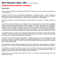
1
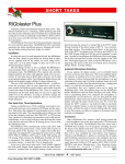
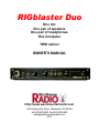
RIGblaster Duo
One mic
One pair of speakers
One pair of headphones
One Computer
TWO radios!
OWNER’S MANUAL
http://www.westmountainradio.com
1020 Spring City Drive, Waukesha, WI 53186
tel 262.522.6503 fax 262.522.6504
[email protected]
2011
PREFACE
Thank you for buying the RIGblaster Duo. Whether you are upgrading from another
RIGblaster, another sound card interface, or this is your first interface, we think you will be
pleased with the capabilities of the duo. After building over 25,000 RIGblaster sound card
interfaces we are pleased to introduce an interface designed especially for a station with two
radios that makes a station neater, simpler, more efficient and easier to operate. It features a
receive monitor switching, mixing and amplification system patterned after an aircraft audio
panel. We hope that you find it makes your station better in every way.
Integrating the audio and switching of a station with two radios is complex but we have made
every effort to make the RIGblaster Duo as easy to operate and toinstall as possible. Front
panel controls are laid out to be intuitive and ergonomically correct. You should be able to
understand the operation simply by looking at the controls. You only need to become
accustomed to having a single mic, a single pair of headphones and using a master volume
control.
Front panel status indicators show at a glance, signal routing, audio source and status of PTT,
CW and FSK control and keying. In addition to seeing the position of the transmit-select
switch, optional external LED indicators are available to be located at each radio to make it
obvious which radio is ready for transmit.
In many ways the installation is actually simpler than other model RIGblasters except that each
radio has its own connections. The installation will be well worth the effort as you will have
your station totally integrated.
This manual is written with a step-by-step approach explaining how to connect and use the
primary features first, and then later the advanced options. You may not want nor need some
of the advanced options so you may ignore them if you wish. Of course if you understand and
know what you want to do, feel free to continue into the manual as we explain how to add
more and more functions and features. It depends on your desire to experiment; in the spirit of
Amateur Radio; that’s what it is all about!
The RIGblaster Duo was conceived as a platform to support all Amateur Radio sound card
software, keying and rig control software, even software that has not yet been written.
2
CONTENTS
PREFACE.................................................................................................................................. 2
CONTENTS ............................................................................................................................... 3
PLEASE NOTE: ......................................................................................................................... 4
AN IMPORTANT NOTE ABOUT STATION GROUNDING:....................................................... 4
UNPACKING ............................................................................................................................. 5
PANEL DESCRIPTION ............................................................................................................. 6
FRONT PANEL ...................................................................................................................... 6
PANEL DESCRIPTION continued ............................................................................................. 7
PANEL DESCRIPTION ............................................................................................................. 8
REAR PANEL ........................................................................................................................ 8
PANEL DESCRIPTION continued ............................................................................................. 9
CHOOSE A MOUNTING LOCATION ...................................................................................... 10
INSTALLATION PLANNING .................................................................................................... 10
INSTALLATION AND CONNECTIONS: BASIC FEATURES .................................................. 11
STEP 1: INSTALL MICROPHONE WIRING JUMPERS ...................................................... 11
STEP 2: CONNECT AUDIO CABLES.................................................................................. 12
OPERATING BASICS ............................................................................................................. 12
SOUND CARD SOFTWARE OPERATION ............................................................................. 14
STEP 1: INSTALL SOFTWARE ........................................................................................... 14
STEP 2: SETUP TO RECEIVE SIGNALS USING SOFTWARE .......................................... 14
STEP 3: SET UP TO TRANSMIT USING SOUND CARD SOFTWARE .............................. 15
STEP 4 -TEST THE USB VIRTUAL COM PORTS .............................................................. 15
TRANSMIT WITH SOUND CARD SOFTWARE: ..................................................................... 16
CW CABLING AND SETUP .................................................................................................... 17
RTTY FSK CABLING AND SETUP ......................................................................................... 17
RIG CONTROL CABLING AND SETUP.................................................................................. 18
STATION HOOKUP DIAGRAM ............................................................................................... 20
STATION HOOKUP DIAGRAM (optional features & functions, in red) ................................... 21
JUMPER DIAGRAMS: MICROPHONE AND RADIOS ............................................................ 23
FOR 8 PIN ROUND SCREW ON MICROPHONES AND RADIOS ONLY ........................... 23
JUMPER DIAGRAMS: RADIOS ONLY ................................................................................... 24
FOR RJ45 MODULAR SQUARE CONNECTOR RADIOS ONLY ........................................ 24
FEATURE SELECTION JUMPER BLOCK OVERVIEW.......................................................... 25
DEFAULT SETTINGS: FEATURE SELECTION JUMPERS, DIAGRAM ............................. 25
MIC ELECTRET BIAS JUMPER – P8 ..................................................................................... 25
RX MUTE JUMPER – P9 ........................................................................................................ 26
PC RX FUNCTION ASSIGN – P5 ........................................................................................... 26
RADIO A RX CHANNEL ASSIGN – P6 ................................................................................... 26
RADIO B RX CHANNEL ASSIGN – P7 ................................................................................... 27
VIRTUAL COM PORT SERIAL SELECT – P4 ........................................................................ 27
TROUBLESHOOTING TIPS.................................................................................................... 27
INDEX...................................................................................................................................... 29
WARRANTY ............................................................................................................................ 30
3
PLEASE NOTE:
In this manual we will refer to the sound device on a computer as “Sound Card”. We
understand many computer sound devices are integrated onto the motherboard of the
computer, or can be external. We will stick to the more familiar wording “Sound Card”. Note
that RIGblasters do not have built in sound. If they did it would mean that you would have to
disable the internal sound system in your computer to use most Amateur Radio sound card
software, because most programs cannot select the computer audio device. All RIGblasters
leave your computer sound fully functional just as it was before, yet you have full capabilities
will all Amateur Radio sound card programs and operating modes.
The words “Radio”, “Transceiver” and “Rig” as used within this document are synonymous.
Throughout this manual any reference to using a computer is worded for a Windows®
computer. You may have to interpret the wording to suit a Mac OS® or Linux® computer to
fully understand references to using a computer.
AN IMPORTANT NOTE ABOUT STATION GROUNDING:
Interconnected electronic equipment, such as an Amateur Radio station, is a system.
Interconnected signal cables must only carry the signals (RF, audio, power or control) they are
meant to. They should never be allowed to be power ground interconnects!
Your station making up this system must be grounded properly at a single point! All desktop
computers, monitors and printers have AC power cord ground connections. The computer AC
ground must be connected to the station ground at a single point. If you radio grounds are not
connected to the same physical location, and AC ground potential; that ground current will be
superimposed on the desired signal.
Simply connect the radio grounds, station grounds and AC grounds together at the same physical
point. Do not daisy chain the grounds from one unit to another! This will not only make all the
equipment work properly as a system but it will be much less likely to have damage from a nearby
lightning strike.
4
UNPACKING
Items included with the RIGblaster Duo
1 - RIGblaster Pro Unit and Cover Screws
1 - DC power cord with Powerpole battery connector
1 - RIGblaster & RIGtalk Software Collection
2 - Microphone Cable (RJ45 to 8 pin screw on)
1 - Microphone Cable (3 foot RJ45 to RJ45 Modular)
1 - USB A to B Interface Cable
8 - Stereo Audio 6ft. Patch Cord (1/8 inch/3.5mm Mini Plug)
1 - Accessories Kit (that contains)
11 White Wire Jumpers
2 Adapters – 1/8 inch (3.5mm) Mini (female) to ¼ inch Plug
4 3M Adhesive Pads (not pictured)
Optional accessories
6 foot microphone cables
External LED indicators (show radio ready to transmit).
FSK keying cables (radio specific)
5
PANEL DESCRIPTION
FRONT PANEL
- MICROPHONE CONNECTOR, 8-Pin Screw-on Microphone Connector – connects almost any make or
model radio microphone to the RIGblaster Duo for use with any other or the same make or model radio.
- “ph” HEADPHONE MONITOR JACK – Accepts stereo headphones with a 1/4 inch plug – may be used with
supplied adaptor for headphones with 1/8 inch plugs.
- “xmit select” TRANSMIT SELECTOR SWITCH – Selects either radio A or radio B to transmit with both a
microphone or computer audio.
- “xmit level” TRANSMIT LEVEL SET – For adjusting the audio transmit drive level coming from the
computer audio output into the Mic input of the radio selected for transmit.
- “rx level” MASTER MONITOR LEVEL SET” – For adjusting the master monitor audio level (volume) for the
entire station - monitored on headphones and/or speakers.
- “radio A” AUDIO MONITOR SELECTOR SWITCH – Selects the audio output of radio A, in three positions:
Off, headphones only, and speakers plus headphones. (also routes the receive audio to the computer for
software receive in either headphone or speaker on positions, but only with the default setting of the PC monitor
jumpers)
- “radio B” AUDIO MONITOR SELECTOR SWITCH – Same as above but selects radio B.
- “PC” AUDIO MONITOR SELECTOR SWITCH – Same as both above but selects audio from the computer.
- “ph level” HEADPHONE LEVEL SET” – For adjusting the headphone monitor audio level (volume) in
relation to the master volume. It is a slave volume control below the master level that sets the headphone volume
in relation to station master volume.
- “c. s.” LED – A yellow LED indicating that the RIGblaster Duo is feeding computer audio (CS: Computer
Sound) to the radio selected for transmit, not microphone audio. It will come on only if activated by sound card
software, thus indicating that the RIGblaster has automatically switched the audio to the computer. Note that it
will turn off, even while activated, if the PTT is overridden by the station microphone PTT switch or rear panel
connected foot switch.
- “ptt” LED – This red LED indicates when PTT is activated directly by your mic’s PTT button, by your foot
switch or indirectly via software through the USB virtual serial port interface.
6
PANEL DESCRIPTION continued
FRONT PANEL
- “cw” LED – This red LED blinks indicating when CW keying is actively being sent by keyboard CW software.
This LED may be on, even with the RIGblaster Duo turned off, if the virtual USB serial port has the DTR line
raised high by computer software controlling the virtual serial port. It will also flash with FSK if you have the
incorrect serial COM number assigned in RTTY software.
- “fsk” LED – This red LED flickers when FSK keying is active with appropriate software for FSK keying.
Under certain conditions, this LED may be on without an active FSK program running in the computer if the USB
virtual serial port has the DTR line active. It will also flash on CW if you have the incorrect serial COM number
assigned in CW software.
- “usb” LED – a green LED indicating the RIGblaster Duo is connected to a computer supplying USB power.
- “power” SWITCH – Turns power ON and OFF. Up is ON and down is OFF.
- “power” LED – a green LED indicating the RIGblaster Duo is turned on.
NOTE: References used throughout this document, such as (R18) refer to the RIGblaster Duo Switch,
Connector, Knob, Jack or LED as illustrated on these PANEL DESCRIPTION pages.
(Fxx) would refer to the above front panel diagram and (Rxx) would refer to the rear panel diagram that
follows.
Example; “This connection is made to the MIC OUT RADIO B (R18) on the RIGblaster Duo”.
(R18) refers to Rear Panel illustration number
so you can quickly locate this particular Switch,
Connector, Knob, Jack or LED on the corresponding diagram.
7
PANEL DESCRIPTION
REAR PANEL
- “INPUT 12VDC” - 12 Volt DC INPUT - connects the Supplied DC Power cord to the RIGblaster
Duo.
- “OUTSW 12VDC” - 12 Volt DC TRIGGER OUTPUT - Provided for future use to control outboard
accessories. Note: if power is plugged in to this jack the power switch will not function and the unit will be alwayson.
- “USB” - USB CONNECTION - For connection to a computer’s USB Interface using the supplied USB cable.
“RIG CTL IN/OUT” TTL CAT/CI-V RIG CONTROL CONNECTIONS
- “RIG CTL B” - RADIO B RIG CONTROL - connects an Icom or TenTec CI-V controlled radio, or certain
model Yaesu TTL CAT and Kenwood TTL controlled radios. Note: Requires an optional control cable compatible
the radio. Not for use with DB9 RS232 level control radios. Always connected to virtual COM B.
- “RIG CTL A” - RADIO A RIG CONTROL - connects an Icom or TenTec CI-V controlled radio or certain
model Yaesu TTL CAT and Kenwood TTL controlled radios. Note: Requires an optional control cable compatible
with the radio. Not for use with DB9 RS232 level control radios. Always connected to virtual COM A.
“KEYING OUTPUTS” CW AND FSK KEYING CONNECTONS
- “CW B” - CW OUT RADIO B - 1/8 MINI JACK - for connection to the CW straight key jack on your radio for
computer CW keying with appropriate software. Compatible with most solid state radios that key with positive pull
down. Connected to virtual COM A but may be changed to B by changing the appropriate jumpers.
- “CW A” - CW OUT RADIO A - 1/8 MINI JACK - for connection to the CW straight key jack on your radio for
computer CW keying with appropriate software. Compatible with most solid state radios that key with positive pull
down. Connected to virtual COM A but may be changed to B by changing the appropriate jumpers.
- “FSK B” - FSK KEYING OUT RADIO B - 1/8 MINI JACK - for connection to the FSK input of your radio for
computer FSK keying with appropriate software. Compatible with most solid state radios that key with positive
pull down. Not needed for RTTY operation with AFSK. By default it is connected to virtual COM B but may be
changed to A by changing the appropriate jumpers.
- “FSK B” - FSK KEYING OUT RADIO B - 1/8 MINI JACK - for connection to the FSK input of your radio for
computer FSK keying with appropriate software. Compatible with most solid state radios that key with positive
pull down. Not needed for RTTY operation with AFSK. Bye default it is connected to virtual COM B but may be
changed to A by changing the appropriate jumpers.
8
PANEL DESCRIPTION continued
REAR PANEL
“RECEIVE AUDIO IN/OUT” RECEIVE AUDIO MONITORING CONNECTIONS
- “SPKR OUT” - SPEAKER OUTPUT - Stereo 1/8 MINI JACK - for connection to either a pair of 4-16 ohm
speakers or to a pair of amplified speakers: any computer or communications speakers of your choice.
CAUTION: use only a stereo plug.
- “PC IN” - COMPUTER AUDIO INPUT - Stereo 1/8 MINI JACK - Plug the line output of your desktop
computer into this jack. Use headphone output on a laptop computer.
- “RADIO B IN” - RADIO B AUDIO INPUT - Stereo 1/8 MINI JACK - for connection to the radio’s speaker
output to monitor the radio. May be mono (tip, sleeve) or stereo (tip ring and sleeve). This is a stereo input that
with internal jumpers may be assigned to left, right, both (dual mono, default) or stereo (dual receive).
- “RADIO A IN” - RADIO A AUDIO INPUT - Stereo 1/8 MINI JACK - for connection to the radio’s speaker
output to monitor the radio. May be mono (tip, sleeve) or stereo (tip ring and sleeve). This is a stereo input that
with internal jumpers may be assigned to left, right, both (dual mono, default) or stereo (dual receive).
- “RCV OUT” - RECEIVE MONITOR OUTPUT - Stereo 1/8 MINI JACK – for connection to the computer
sound Line Input (Mic input on a laptop). To monitor either or both radios using Amateur Radio sound card
software. The default configuration is to monitor whichever radio/radios are selected for headphone monitoring.
Using internal jumpers it may also be configured so one radio is fed to the left channel, and the other to the right
channel, in stereo, so that they may be selected by the sound card balance control.
“LEDS” READY TO TRANSMIT INDICATOR CONNECTIONS
- “XMIT LED B” RADIO B XMIT LED INDICATOR OUTPUT - 1/8 MINI JACK - for connection to an external
accessory LED indicator to be placed near the corresponding radio to make it obvious which radio is selected and
ready to transmit. (This must be used with the correct accessory LED indicators otherwise damage may occur!)
- “XMIT LED A” RADIO A XMIT LED INDICATOR OUTPUT – 1/8 MINI JACK – for connection to an external
accessory LED indicator to be placed near the corresponding radio to make it obvious which radio is selected and
ready to transmit. (This must be used with the correct accessory LED indicators otherwise damage may occur!)
“RIG: MIC/PTT” RADIO MIC OUTPUT AND PTT SWITCH INPUT CONNECTIONS
- “PTT IN” – PTT SWITCH INPUT JACK - RCA PHONO JACK - for connection to an auxiliary foot switch or
desk mounted switch that is not part of the main station microphone.
- “MIC OUT B” – RADIO B MICROPHONE OUTPUT - RJ45 MODULAR JACK – for connection to the
Microphone connector on radio B. This connection is made using one of the included Mic Cables or an optional 6
foot mic cable.
- “MIC OUT A” – RADIO A MICROPHONE OUTPUT - RJ45 MODULAR JACK – for connection to the
Microphone connector on radio B. This connection is made using one of the included Mic Cables or an optional 6
foot mic cable.
9
CHOOSE A MOUNTING LOCATION
The supplied microphone cables are 3 feet long and the computer cables are 6 feet long. Choose a
location that allows these cables to reach your radios and your computer. You may extend the
computer cables within reason or you may purchase optional 6 foot microphone cables. It makes
sense to have your computer at your operating position with the radios. Do not attempt to run the
RIGblaster Duo with a computer across the room, especially if it is on a different house wiring circuit
than your ham station. Put your radios and computer together so everything is at your fingertips for
maximum operating convenience. The RIGblaster Duo is intended to help make your station
convenient to use. If possible set up your station so you have access to the back panels of all the
equipment.
Note: the top cover can be removed without disconnecting the cables, for easy access to the internal
jumpers. Therefore, if possible, mount the RIGblaster Duo where you can remove the cover.
If you will be using a hand microphone with a coiled cord, consider the tug on the cord. The RIGblaster
Duo is fairly heavy but could be pulled around by a coiled mic cord. Use the supplied double sided
foam stick-on pads as an easy way to secure it.
Locate the RIGblaster Duo at least 18 inches from anything that has a strong magnetic field, such as
transformer type power supplies, amplifiers, CRT type monitors or rotor control boxes. Do not put the
RIGblaster Duo in strong RF fields.
The RIGblaster Duo requires little ventilation and can be put in any cool location that does not block
the ventilation for another piece of equipment that does require ventilation.
INSTALLATION PLANNING
This instruction manual is written, and the RIGblaster Duo is designed, to accommodate any operator
no matter what equipment he or she may have, or what type of operating they would like to do. Beyond
the basic function of the RIGblaster Duo as a station integration console there are many other options
from which to choose. This would depend on how you wish your station to work and what type of
operating you would like to do.
Advanced options are towards the back of this manual and the basic installation and operation is first.
Continue through this manual, in order, front to back to make setting up the RIGblaster Duo an easy
step by step process. Start with the primary functions and later explore the advanced options.
We will proceed in order. After you have your station set up to operate more conveniently than ever
before we will discuss operation with Amateur Radio sound card software. Next we will cover
advanced options, including; CAT/CI-V rig control, CW, FSK keying and special audio routing.
Only attempt a full configuration of the RIGblaster Duo from the start if you have a complete
understanding of exactly what you wish to do and how you would like your station to operate. You also
need an understanding of how these advanced options function, how they are used, their intended use
and why you would want them; before attempting to configure everything at once.
10
INSTALLATION AND CONNECTIONS: BASIC FEATURES
STEP 1: INSTALL MICROPHONE WIRING JUMPERS
1) Every brand of radio and every brand of microphone has different wiring even though they use the
same connectors. The RIGblaster Duo uses a set of three jumper blocks to easily accommodate
using almost any brand or type of mic with almost any radio. The connectors only need to mate; the
wiring scheme is fully configurable.
2) Take off the cover by removing the four cover screws. Locate the three jumper blocks. You will see
jumper block P10 for the microphone, P2 for radio A and P3 for radio B. Decide which radio will be
radio A and which will be B. (Perhaps the top radio should be A, or if they are side by side your main
radio could be A, and the one you use less, B.)
3) You may use any brand of mic with any two different or same brand, of radios. For example: a
Kenwood mic will work with an Icom and a Yaesu radio. Any brand of dynamic or electret mic should
work as long as it connects with a screw-on 8 pin round metal connector. Note: mics that require a
separate power lead from the radio will not work with a RIGblaster Duo. Also be aware that only the
PTT button on the mic will function; other microphone buttons are not connected and will not work.
4) To install the microphone jumpers refer to the diagrams starting on page 23 of this manual. There
are separate diagrams for 8 pin round and RJ45 square connectors. Note: even for the same brand of
radio different connectors have different wiring! Make sure that you identify the correct diagram not
only for the brand of radio or mic but also what type of connector it uses.
Install the jumpers for your microphone and each one of your radios. If you have two different types of
radios make sure to keep track of which radio you designate as radio A and which you designate as
radio B.
5) Connect your microphone to (F1) the microphone connector on the front of the RIGblaster Duo.
Two 8 pin round microphone cables and one RJ45 cable are supplied with your RIGblaster Duo.
Connect the appropriate cables between the RIGblaster’s (R19) A; and the (R18) B outputs to radios
A and B. If you need longer cables or different types of cables they are available as accessories.
6) Connect the RIGblaster DC cord between (R1) and a regulated and filtered 12 volt (nominal 13.8 V)
source capable of supplying at least 1 amp. Plug the Powerpole connector into a RIGrunner power
panel or adapt it to whatever you have, being careful to observe correct polarity.
7) Turn the RIGblaster power switch (F15) on and check that the green power LED lights. Select radio
A with the transmit selector switch (F3). Confirm that your mic and your PTT switch work correctly on
radio A; then try radio B. Get on-the-air audio reports; do not rely on meter indications! If your mic
works perfectly on both radios, the jumpers are installed correctly.
At this point, if and only if your mic works perfectly with both radios, continue to the next step.
11
STEP 2: CONNECT AUDIO CABLES
Turn off your radio, your computer and RIGblaster before connecting cables.
1) Disconnect your computer speakers and any external radio speakers. Choose the best pair of
amplified or unamplified speakers. They do not have to be a matched pair but that is preferred for
playing music. You may use any pair of 4-16 ohm speakers or any amplified computer speakers. Some
amplified computer speakers are may be susceptible to picking up RF interference. Our RF resistant
COMspkrs are designed to solve that problem. Connect the speakers to the (R10) speaker out jack.
This jack is a stereo jack with the tip left, ring right and sleeve common. A cable is not supplied
because most computer speakers have a matching stereo connector, or you may have to fabricate a
speaker cable to connect a pair of unamplified speakers.
2) Use the supplied 1/8” stereo mini phone plug cables and connect the speaker output of radio A to
“RADIO A IN” (R13). Likewise, connect radio B to (R12).
3) Connect your computer’s line output, usually a green socket
use the headphone jack
on the back of a computer, (laptops
) to the to the PC IN (R11) jack on the RIGblaster Duo.
3) Turn on the RIGblaster, your radios and computer. Turn radio A’s volume control (AF gain) about
half way up (12 o’clock). Select radio A on the RIGblaster by flipping the “radio A” switch (F6) to the
up/top position. Turn up the “rx level” (master volume) knob (F5) on the RIGblaster and you should
hear radio A coming from your speakers. Try the Same thing with radio B using the “radio B” (F7)
switch. Play music or cause your computer to generate audio and select “PC” (F8) and you should
hear you computer.
4)Plug headphones into the RIGblaster (F2) and turn up the RIGblaster’s “ph level” (headphone sub
volume) knob (F9) and you should hear the same thing coming out of your headphones that is coming
out of your speakers.
Experiment with all the controls!
Congratulations! This completes the basic installation of the RIGblaster Duo. Your station will be
much neater and more convenient to use, while doing everything it did before.
OPERATING BASICS
You must have the RIGblaster turned on in order to operate your station. Note that there is a 12 volt
remote trigger output on the back (R2) provided to turn your entire station on or off. Look for future
accessories from West Mountain Radio to do this or home brew a box with 12 volt relays to control your
station’s DC, AC or both.
BASIC FUNCTIONS:
TRANSMIT SELECT is done by using the “xmit select” (F3) to select which radio will be used for
transmitting. Either your PTT switch or computer will activate transmit and the audio will be
automatically selected between the mic and computer. The position of the switch indicates which is
selected, A or B. Remember which radio is which and that A is up and B is down. In the heat of a
contest you will hardly have to look at the switch as you will become used to selecting you’re radio by
“feel”. You may also connect transmit ready LED indicators to be located remotely on each radio to
make it more obvious which radio is ready to transmit.
12
RECEIVE MONITORING allows selection of any combination of radio A, B and/or the computer to hear
on speakers and/or headphones. Each input (audio source) has a switch with three positions, “off”
(down), “hp” (headphones only, center) and “both” (headphones and speakers, up). The three inputs
are mixed together and capable of stereo operation. The default configuration, set by internal jumpers
(see advanced options), is so radio A and B are played through both channels in dual-mono.
VOLUME ADJUSTMENT is quite flexible but you will have to experiment with it and get used to it.
Each radio has a volume adjustment as does your computer, and you should already be familiar with
these controls. You may also be using amplified speakers with their own volume knob.
The RIGblaster Duo has two volume knobs. The “rx level” (F4) is the master volume for the entire
station! You will have to get used to using it as the main volume for the station. For example, if the
phone rings or the family calls it can be used to turn down the entire station.
There is also a separate “ph level” (F9) headphone volume control. The headphone volume is
controlled by this knob in relation to how loud the master volume is set. This allows you to set the
headphones louder or softer than the speakers. Note: now you can work that weak station you can
barely hear on your speakers simply by putting your headphones on. Your headphones will be playing
the same thing, they are already plugged in and they can be set louder than your speakers.
To setup the volume for the entire station, set each radio’s AF level (volume control) about half way up.
Set your computer’s virtual sound card level control about 2/3 of the way up. If you have amplified
speakers with a volume knob set that about 2/3 of the way up. Start by selecting radio A to play on
speakers and headphones, “radio A” (F6) in the up position. Turn up the “rx level” for a comfortable
volume. Turn off A and turn on B, set that radio’s AF level to match your other radio. Next do the same
thing with the computer, using the virtual master volume slider. Now experiment with switching
between the sources and listening to more than one source at a time. You will find you can balance
everything the way you wish and to use the master “rx level” as the main volume. It will take you awhile
to get out of the habit of using the knobs on the radios or computer slider, leave them alone. Plug in
headphones and experiment with the “ph level” and selectors. You will quickly get used to controlling
everything from the RIGblaster Duo central location.
We hope that you find the basic operation completely intuitive and obvious, simply by looking at the
front panel of RIGblaster Duo and experimenting with the controls.
13
SOUND CARD SOFTWARE OPERATION
STEP 1: INSTALL SOFTWARE
Insert our CD in your CD ROM drive. The West Mountain Radio screen will pop up in a few seconds.
From our screen click the “XMIT” button for “West Mountain Radio RIGblaster Software Collection”.
Then click the “XMIT” button for whatever mode you would like to try. We highly suggest starting with
PSK31 on 20 meters, 14.07015 using the WinPSK program. Select you program choice and follow the
installation prompts that will appear on the screen to install that software. Close the West Mountain
Radio Window and put the West Mountain Radio CD in a safe place. Your program is now installed.
From Windows®, click, “Start”, “Programs”, find your program icon and click to start that program.
STEP 2: SETUP TO RECEIVE SIGNALS USING SOFTWARE
Turn off your radios and the RIGblaster Duo before connecting cables to either unit.
Connect a supplied patch cord between the RIGblaster Duo’s “RCV OUT” (R14) and your computer’s
(mic
on a laptop).
line input, usually a blue socket
Select one radio or the other to be monitored on headphones, or speakers and headphones. Tune in
an appropriate signal for the mode you have selected. On our CD you will find a chart of standard
operating frequencies for the various modes. To get a better understanding of what to listen for when
tuning, our CD also contains recordings of many of these exciting new modes.
Every sound card has several virtual control panels with many things to click on. There are virtual
controls that either set what is being fed into the computer from the outside world or they control what
comes out of the computer. Think of the input as receive controls and the output as transmit controls.
Generally they are completely independent, and one has nothing to do with the other. You must
understand which is which! Be aware that things vary from computer to computer with different
operating systems, user interfaces and sound card control panel software.
On most Windows® computers the input control panel is labeled “Recording” and the output is labeled
“Volume”. Make sure you are using the input control panel to set your receive input! You have already
turned your radio’s volume control (AF Gain) about half way up. Be sure you tune in and hear
appropriate signals, for the software you are using on your speakers and/or headphones. Turn up and
on (select or un-mute) the sound card input that corresponds to the input you are using, mic or line, on
your “Recording Control” panel until you see a signal properly displayed on the ham radio sound card
software waterfall or similar screen.
Follow the instructions or help files that came with the software you are using to confirm that the signals
from your radio are displayed correctly and that you have tune in the station using your radio and/or the
software tuning controls.
You should now be receiving and copying station with the software you have chosen, , SSTV or
whatever. Try tuning in several other stations or even try another program or mode.
14
STEP 3: SET UP TO TRANSMIT USING SOUND CARD SOFTWARE
USB DRIVER INSTALLATION: (For Windows® only! Mac® or Linux® may be similar)
Whenever you connect any new USB device to a computer you must install driver software. The
CDROM supplied with your RIGblaster Duo has the driver files you need.
Plug the supplied USB cable between (R3) on the RIGblaster and the USB socket on your computer
that you plan to use permanently. The Windows® plug & play wizard should pop up in a few seconds.
Let the wizard automatically install the drivers. If your computer is not on-line the it will get the drivers
from the Microsoft® driver update server and if you are not on-line it will get drivers from the
RIGblaster/RIGtalk CD that should be in your CD ROM drive.
Note: there are actually four driver installations; two USB and two virtual serial COM devices. You must
successfully complete the four driver installations; two USB and two virtual COM ports.
WARNING: if you stop, or cancel at any point it will be a difficult to correct your mistake!
Once you have completed the driver installation you must check to verify the installation. Right click
“My Computer”, left click “Properties”, select the “Hardware” tab, and then click “Device Manager”. The
“Device Manager” will show you a list of all of the hardware currently operating with your computer.
Scroll down and click the plus sign next to “Ports (COM & LPT)” to expand that category and show the
installation details. You should see two entries for a WMR RIGblaster Duo (COMxx). If they are both
there the installation was successful. At this time make a note of the COM port numbers (xx) and
record the upper one as the RIGblaster Duo COM A port number and the lower one as COM B. Note
that these numbers are dynamically assigned by Windows® and can be changed to other port numbers
if that number is not actually in use.
STEP 4 -TEST THE USB VIRTUAL COM PORTS
Turn on the RIGblaster Duo Power Switch. The Green “Power” LED (F16) and the Green “usb” LED
(F14) should come on. At this time no other LED should light. Unplug the USB cable and then plug it
back in. You should see the “c.s.”, “ptt”, and “cw” LEDs flash several times as the USB port initializes.
You should also see whichever radio is selected to transmit and turned on have its PTT activated
momentarily.
15
TRANSMIT WITH SOUND CARD SOFTWARE:
All Amateur Radio sound card software is meant to control PTT via a serial interface. In order for any
program to do this you must set it up to control PTT by “telling” the software what COM port number
has PTT control interface (RIGblaster) connected. Read the software help files to learn where and how
to do this. Generally you must find a setup or configuration menu item for PTT control. Once you find
where to configure PTT set it to the COM port number assigned to the RIGblaster COM A that you
found in your Windows® “Device Manager”. You should set it to control PTT on the RTS line, if you
have a choice of RTS or DTR. DTR should be off because it is usually used for CW keying by CW
programs.
At this point you may test the software and RIGblaster for PTT control. Make sure the RIGblaster Duo
is turned ON and turn down the “xmit level” knob. Put your radio in the USB mode and click the virtual
transmit on button on your software. You should see the RIGblaster “c.s.” LED and “ptt” LEDs come
on, and the selected radio, A or B, indicate PTT activation. You should not be putting out a signal
during this test as the audio drive is turned down. If the RIGblaster is set to monitor the computer you
should hear the tones that the software is generating.
If you have been following these instructions you have already set your sound card output “Volume
Control and Wave” sliders so leave them where they were. If you did not set the computer output or
you have changed it go back and do it again.
Open your Windows® sound “Volume” control panel (double click on the little speaker icon in the task
bar) and un-mute the “Wave” output and the left hand “Volume Control” output. The left “Volume
Control” and “Wave” virtual sliders should still be set to where you had previously set them to monitor
computer audio. Also, the virtual left/right balance sliders should already be in the center.
Set your radio to upper sideband (USB) and use your normal mic gain setting, turn your speech
compressor off and set the transmitter RF drive (power control) all the way up. You will want to use a
dummy load for this procedure. For most sound card software you should make sure that the transmit
audio is between 500Hz and 2500 Hz, otherwise you may be outside the limits of the response of your
transmitter and you may not be able to transmit properly.
Set your software to transmit or tune, then slowly turn up the “xmit level” knob (F4) on the front of the
RIGblaster Duo to the point where your power meter shows the power level you can safely run. Your
final setting MUST produce less than full RF power output from your radio. WARNING: you should not
exceed the continuous AM, FM or RTTY power rating of your radio.
After this setting is completed, check to make sure your RF drive (power control) is set to maximum and
that your RF power output shows less than maximum. Even if your radio is rated at full output and
continuous duty, do not set the audio to drive to full output! You would get a wide distorted signal!
With an FM rig you must set the audio level with the “level set” Knob using a deviation meter or by
comparing the level of your transmit audio to other stations using another receiver.
For a more information about Computer Sound Cards, see the article titled “The In’s and Out’s of a
Sound Card” in October 2003 QST. Also available in PDF format on our Web Site at:
http://www.westmountainradio.com/pdf/Ins&Outs.pdf.
16
CW CABLING AND SETUP
Turn off your radios and the RIGblaster Duo before connecting cables to either unit.
There are two optically isolated CW keying outputs to be used with CW software. These outputs
always function and key together. You have three ways to determine which radio transmits. You can
use two different COM ports for PTT control, you can use semi-break in keying and only select one
radio or you can use a PTT switch selected by the RIGblaster “xmit select” switch.
Connect patch cords between the CW OUT (R6) and (R7) jacks on the rear panel of the RIGblaster
Duo and plug the other ends into the straight key CW jacks on your radios. If the CW Key jack on your
radio is a ¼” jack, use the supplied 1/8” to ¼” adapters. For computer CW make sure your radio CW
keying is set for “Straight Key” mode for the jack you are using. Many radios have a CW straight key
jack on the rear, or one of the two jacks may be set to straight key operation via a radio menu setting.
The remaining setup for computer controlled CW will be done in the application software you choose.
Control of CW is not selectable and will always be controlled by the DTR line of the Serial Port for CW.
Make sure when you configure your software that you observe this convention.
On the CW OUT jacks, the sleeve goes to common ground and the tip goes to the keying circuit, the
ring of this connector is not used.
RTTY FSK CABLING AND SETUP
Turn off both your radios and the RIGblaster Duo before connecting cables to either unit.
There are two optically isolated FSK keying outputs to be used with RTTY FSK keying software. These
outputs always function and key together. You have two ways to determine which radio transmits. You
can use two different COM ports for PTT control or use a PTT switch selected by the RIGblaster “xmit
select” switch.
Your radio will have to be capable of RTTY/FSK to utilize this option. FSK wiring is unique to each
amateur radio transceiver manufacturer, therefore you will have to consult your specific radio owners
manual for information about how to connect to the FSK input of your radio.
For many radios, the FSK connection is via an accessory connection on the rear panel of the
transceiver. West Mountain Radio has ready-made cables for connection between a RIGblaster and
the FSK input of many Icom, Kenwood and Yaesu radios. They are available on our web site
http://www.westmountainradio.com under other RIGblaster Accessories.
After you have constructed or purchased the correct FSK cable, connect the mini plug end to FSK
OUT, either (R8) or (R9) on the rear panel of the RIGblaster Duo. Connect the other end of this cable
to the appropriate FSK input keying connection on your transceiver. Always check the wiring prior to
connecting homemade cables to your equipment.
On the FSK OUT (R8) and (R9) jacks, the sleeve goes to common ground and the tip goes to the FSK
keying circuit, the ring of this connector is not used.
Make any necessary jumpering on the P4 jumper block as described later in this manual under
VIRTUAL COM PORT SERIAL SELECT – P4.
17
Unlike RTTY AFSK which is normally operated in LSB you will have to operate your radio in RTTY
mode to enable FSK keying input.
Amateur radio FSK keying is at 45 baud and modern USB to serial converters do not support this low
baud rate or 5 bit operation. Therefore the only program available for FSK via a USB interface is
MMTTY used with the EXTFSK extension. This program would normally be configured to use RTS for
PTT and DTR for FSK, like CW. Since the RIGblaster Duo has two serial emulators you may
configure the serial jumper block so that one is for CW and the other for RTTY FSK.
RIG CONTROL CABLING AND SETUP
RIG Control cabling and jumpering differs depending on the radio manufacturer.
Most ICOM and TenTec (with CI-V) use a single bi-directional conductor and thus require a patch cord
that is stereo on one end and mono on the other (tip and ring on the RIGblaster Duo end and both of
those wires connected together to tip on the radio end).
With a Yaesu it is a little more complicated. The Yaesu CAT system uses three wires and they have
different connectors and pin wiring arrangements for different models. Older Yaesu radios require the
rig control TTL (5 volt) level converter built into the RIGblaster Duo. West Mountain Radio has readymade CI-V and CAT accessory cables available for various TTL level controlled radios.
There are two rig control outputs; “RIG CTL A” on the virtual COM port A and “RIG CTL B” on virtual
COM port B so that you may independently control two different radios.
To use rig control connect the proper cable between the corresponding rig control outputs and each
radio. You must then configure your rig control software, and possibly radio, for the correct COM port
number as noted in the Windows Device Manager. An exact match for radio make and model, baud
rate, parity, stop bits for proper communication is essential. NOTE: if any one item is incorrect you will
have absolutely no rig control function.
18
19
STATION HOOKUP DIAGRAM
.
The diagram on the preceding page shows a RIGblaster Duo integrated into an Amateur Radio Station
consisting of two transceivers, a desktop computer with sound, two speakers, a foot switch and LED
transmit ready LED indicators. This is a diagram of the connections for a fully integrated station. The
only accessory that is not shown is a pair of stereo headphones which would be plugged into the front
of the RIGblaster Duo.
The primary features are indicated with blue lines and are explained first. The optional advanced
features are indicated in red and will be explained later in this manual. For each numbered wire there is
a description of its function and the end points to which it connects.
- The station microphone with an 8 pin round metal connector is connected to the
Microphone Connector (F1) on the front of the RIGblaster Duo. Note: in order for this cable to
function properly with a particular microphone, jumpers must be installed correctly inside the
RIGblaster on the “P10” jumper block, see page 24.
“RIG MIC/PTT’
- This is a supplied microphone cables connecting “MIC OUT A” (R19) to radio A’s front
panel microphone input. It is either a 8 pin round metal connector to a square RJ45 Modular
connector or an RJ45 to RJ45 Modular. Other cables for 4 pin round, RJ22 6 wire Modular or
special 6’ long cables are available. Note: in order for this cable to function properly with a
particular radio jumpers must be installed correctly inside the RIGblaster on the “P2” block. See
page 25.
- This is a supplied microphone cables connecting “MIC OUT B” (R19) to radio B’s front
panel microphone input. It is either a 8 pin round metal connector to a square RJ45 Modular
connector or an RJ45 to RJ45 Modular. Other cables for 4 pin round, RJ22 6 wire Modular or
special 6’ long cables are available. Note: in order for this cable to function properly with a
particular radio, jumpers must be installed correctly inside the RIGblaster on the “P3” block. See
page 25.
“RECEIVE AUDIO IN/OUT”
- This is a supplied stereo mini plug Patch Cord that connects the Computer Sound Card Line In (usually blue) to the RIGblaster Duo “RCV OUT” (R14). This connection allows
Amateur Radio sound card software to monitor the signals from both radios. Note: For a laptop
computer you would use the microphone input
.
- This is a supplied stereo mini plug Patch Cord that routes speaker level audio from Radio
A’s speaker output to the RIGblaster Duo’s “RADIO A IN” (R13). It provides a path for audio
from the radio to the RIGblaster. This normally disables the built in speaker in the radio allowing
you to use the main station speakers and headphones driven by the RIGblaster. Note: for
radios with stereo (left and right) dual receive you must change the default setting of the P6
jumpers (see advanced options page 27).
- This is a supplied stereo mini plug Patch Cord that routes speaker level audio from Radio
B’s speaker output to the RIGblaster Duo’s “RADIO B IN” (R12). It provides a path for audio
20
from the radio to the RIGblaster. This normally disables the built in speaker in the radio allowing
you to use the main station speakers and headphones driven by the RIGblaster. Note: for
radios with stereo (left and right) dual receive you must change the default setting of the P6
jumpers (see advanced options page 27).
- This is a supplied stereo mini plug Patch Cord that routes line level audio from the
computer’s line output (usually green) to the RIGblaster Duo’s “PC IN” (R11). It provides a
path for audio from the computer to the RIGblaster Duo. This is a Hi-Fi stereo connection. For
a laptop computer you would use the headphone output
.
- This is a cable (not supplied with the RIGblaster Duo) that connects the RIGblaster Duo
to a stereo pair of speakers such as the West Mountain Radio COMspkrs. The speakers must
have a stereo mini plug. These speakers may be any make or model of stereo amplified
computer speakers or any un-amplified speakers between 4 and 16 ohms.
“POWER AND USB”
- This supplied computer USB type A to type B cable connects the RIGblaster’s “USB”
socket to one of the computer’s USB sockets. Do not plug in this cable unless you have read
the instructions on doing this and are ready to do the USB software driver installation.
- This supplied DC cord with a Powerpole connector and coaxial connector supplies power to
the RIGblaster Duo. It plugs into the “INPUT 12VDC” (R1) jack. The Powerpole connector
plugs into any well filtered nominal 13.8 Volt DC source capable of supplying at least 1 Amp. If
you do not have a RIGrunner with Powerpoles you may cut off that connector and connect it by
some other method but be certain the polarity is correct (Red +, Black -).
STATION HOOKUP DIAGRAM (optional features & functions, in red)
“RIG: MIC/PTT”
- This yellow RCA jack (R16) connects a user supplied external PTT foot switch or other
switch. It is an input connector to control PTT in addition to the PTT switch in the microphone.
“LEDS”
- This cable is supplied with an optional LED transmit ready indicator, for radio A. The
attached LED (R15) will light red whenever radio A is selected for transmit whether or not it is
actually transmitting.
- This cable is supplied with an optional LED transmit ready indicator, for radio B. The
attached LED (R14) will light red whenever radio B is selected for transmit whether or not it is
actually transmitting.
“KEYING OUTPUTS”
- This is a optional custom cable to connect between radio A’s FSK keying socket and the
“FSK A” (R9) output and is used for RTTY/FSK operation (presently only with MMTTY EXTFSK
software). It is not needed for AFSK RTTY operation with any other software. Note: the default
21
configuration of jumper block P4 is configured to key this jack with DTR on COM B using the
MMTTY EXTFSK software extension (See page 28 for the P4 jumpers).
- This is a optional custom cable to connect between radio B’s FSK keying socket and the
“FSK B” (R8) output and is used for RTTY FSK operation, presently only with MMTTY software.
It is not needed for AFSK RTTY operation with any other software. Note: the default
configuration of jumper block P4 is configured to key this jack with DTR on COM B using the
MMTTY EXTFSK software extension (See page 28 for the P4 jumpers).
- This is for a supplied mini plug Patch Cord, and mini to ¼” phone plug adaptor, to interface
between radio A’s CW keying (straight key) socket and the “CW A” (R7) keying output for CW
operation using keyboard CW software. Note: the default configuration of jumper block P4 is
configured to key this jack with DTR on COM A (See page 28 for the P4 jumpers)..
- This is for a supplied mini plug Patch Cord, and mini to ¼” phone plug adaptor, to interface
between radio B’s CW keying (straight key) socket and the “CW A” (R6) keying output for CW
operation using keyboard CW software. Note: the default configuration of jumper block P4 is
configured to key this jack with DTR on COM A (See page 28 for the P4 jumpers)..
“RIG CTL IN/OUT”
- This is an optional CAT or CI-V interface cable connected between (R5) radio A’s CAT or
CI-V interface. It is used for a computer to exchange frequency, band and other information. It
controls a radio using the USB serial converter TXD and RXD lines on COM A. This interface is
always controlled by COM A!
- This is an optional CAT or CI-V interface cable connected between (R4) radio B’s CAT or
CI-V interface. It is used for a computer to exchange frequency, band and other information. It
controls a radio using the USB serial converter TXD and RXD lines on COM B. This interface is
always controlled by COM B!
22
JUMPER DIAGRAMS: MICROPHONE AND RADIOS
FOR 8 PIN ROUND SCREW ON MICROPHONES AND RADIOS ONLY
Used on the P10 jumper block for microphones, and the P2 and P3 jumper blocks with 8 pin round
connector radios only.
ALINCO, KENWOOD, SGC and ELECRAFT with 8 Pin Screw on Microphone Connectors
Pin #
1
2
3
4
5
6
7
8
-
MIC
PTT
NC
NC
NC
NC
MIC GND
PTT GND (OPTIONAL*)
ICOM with 8 Pin Screw on Microphone Connectors
Pin#
1
2
3
4
5
6
7
8
-
MIC
NC
NC
NC
PTT
PTT GND (OPTIONAL*)
MIC GND
NC
YAESU with 8 Pin Screw on Microphone Connectors
Pin #
1
2
3
4
5
6
7
8
-
NC
NC
NC
NC
PTT GND (OPTIONAL*)
PTT
MIC GND
MIC
*The “PTT GND” connection should always be used on the P10 microphone jumper block but it is
optional on the P2 and P3 Jumper blocks. It is normally used except in special cases. For more info
contact West Mountain Radio support.
23
JUMPER DIAGRAMS: RADIOS ONLY
FOR RJ45 MODULAR SQUARE CONNECTOR RADIOS ONLY
Used on the P2 and P3 jumper blocks for use with RJ45 mic connector radios only.
KENWOOD with RJ45 Microphone Connectors.
Pin #
1
2
3
4
5
6
7
8
-
NC
NC
PTT GND (OPTIONAL*)
PTT
MIC GND
MIC
NC
NC
ICOM with RJ45 Microphone Connectors
Pin #
1
2
3
4
5
6
7
8
-
NC
PTT GND (OPTIONAL*)
MIC
MIC GND
PTT
NC
NC
NC
YAESU with RJ45 Microphone Connectors and most, but not all Yaesu FM rigs
Pin #
1
2
3
4
5
6
7
8
-
NC
PTT GND (OPTIONAL*)
PTT
MIC
MIC GND
NC
NC
NC
*The “PTT GND” connection should always be used on the P10 microphone jumper block but it is
optional on the P2 and P3 Jumper blocks. It is normally used except in special cases. For more info
contact West Mountain Radio support.
24
FEATURE SELECTION JUMPER BLOCK OVERVIEW
The RIGblaster Duo has great flexibly for controlling how you might wish your station to work. In
addition to the three microphone jumper blocks that allows the RIGblaster Duo to operate with almost
any radio or microphone, there are seven other jumper blocks to allow you to customize the features
and functions.
For most operators the default settings of the jumper blocks will be the best choice. If you like the
default operation of your new RIGblaster Duo, just leave everything alone. However, if you know how
you would like your station to work, you would like to know what your options are, and you like to
experiment………. read on.
If you lose track of what you did while experimenting, here is a diagram of the default jumper settings.
DEFAULT SETTINGS: FEATURE SELECTION JUMPERS, DIAGRAM
MIC ELECTRET BIAS JUMPER – P8
The P8 jumper block enables “MIC BIAS” required to use an electret microphone, or disables it for a
dynamic mic. By default there is a blue jumper installed which enables bias to power an electret mic.
This is compatible with a dynamic mic but if you are absolutely positive that your microphone has a
dynamic element, not electret, you may remove this jumper. Leaving the jumper on will not noticeably
effect the performance of most dynamic mics but removing it will totally disable an electret mic.
25
RX MUTE JUMPER – P9
The “RX MUTE” jumper is located on P9. By default there is a blue jumper installed which causes the
entire station’s monitored audio to mute whenever you activate PTT on either radio via the mic or rear
panel PTT switch. It does not mute if PTT is activated by computer software, allowing you to monitor
the transmitted tones from the computer. Most radios normally mute the receive audio on transmit but
this RIGblaster Duo feature also mutes the other radio and/or computer.
To operate cross band, or use the monitor feature of a radio remove the P9 jumper to disable audio
muting on transmit.
PC RX FUNCTION ASSIGN – P5
The “PC RX” function assign gives you two options to feed audio to sound card software from two
radios.
With the default option neither radio’s audio output goes to the computer audio input unless it is
selected with the RIGblaster monitor select switches. If you select either radio it goes to left channel of
the sound card input (tip). If you select both radios, both of them are connected and the audio is mixed
together. You can monitor two radios with one program, which could come in handy to chase digital DX
on two bands.
The other option is to have radio A always goes to the right channel and radio B always goes to the left.
With this option you may monitor either or both radios by moving both jumpers from the two left hand
sets of pins to the two right hand sets, as shown.
Default, RX monitor switches
select radio sent to PC left chan.
Both radios, left and right in
stereo, radio B left, radio A right
RADIO A RX CHANNEL ASSIGN – P6
There are many options and considerations with the configuration of how this feature jumper might be
set. Please read this section carefully.
The RIGblaster Duo is a stereo audio device, that is all the inputs and outputs are pairs of channels,
normally referred to as left and right. Since most radios, but not all, are mono we have given you the
maximum flexibility, as follows.
1) Default, single receive radio (mono)
to both left and right (dual mono).
2) Single receive radio, right channel only.
26
3) Single receive radio, left channel only.
4 Dual receive radio (stereo two channel output),
both channels in stereo, right and left.
RADIO B RX CHANNEL ASSIGN – P7
This is the same as above except that it is assigns radio B and is set on the P7 jumper block.
VIRTUAL COM PORT SERIAL SELECT – P4
The RIGblaster Duo has two virtual COM ports from one USB connection. There is provision to use
either of these ports for whatever function you want. Take into consideration what combination of
software applications you might want to use at the same time before deciding if you need to change
anything.
Your choices for each of the virtual COM ports, A and B, are PTT, CW keying and RTTY/FSK keying.
Besides being able to choose which one of these virtual ports does which one of those functions you
have two ports for CAT/CI-V rig control. Rig control uses the RXD and TXD serial pins and those are
permanently assigned to COM A for radio A and COM B for radio B.
The default configuration is:
PTT on RTS of COM A
CW on DTR of COM A
FSK on DTR of COM B
To change port assignments for a given function simply move the jumper to the other COM port letter.
Note: normally you would not assign two COM ports to do the same thing. Therefore do not assign CW
and FSK to the same COM port. Note: to key FSK DTR use MMTTY software with the EXTFSK
extension.
TROUBLESHOOTING TIPS
Hum in audio monitor with speakers or headphones: Interconnected electronic equipment is a
system. The signal cables must only carry the signals they are meant to. They should not be allowed to
be ground interconnects. Your station making up this system must be grounded properly at a single
point. All desktop computers, monitors and printers have AC power cord ground connections. The
27
computer AC ground must be connected to the station ground at a single point. If your radio grounds
are not connected to the same physical location, and AC ground potential; that ground current will be
superimposed on the audio signal.
Simply connect the radio grounds, station grounds and AC grounds together at the same physical point.
Do not daisy chain the grounds from one unit to another! This will not only make all the equipment
work properly as a system but also it will be much less likely to have damage from a nearby lightning
strike.
No receive: Make sure you have the sound card input you are using on the (“Recording Control”)
panel, turned up and selected! Make sure that you have the radio selected for monitoring on
headphones or both. If you can hear your radio coming out of the speakers or headphones, check that
the “RCV OUT” is connected to your computer’s line input (mic on a laptop).
Transmit PTT is not activated by sound card software: Read the software help and make sure you
have the software set to communicate PTT control via RTS to the virtual serial port A (default) or to B if
you have changed the COM port by moving the P4 PTT jumper. You must look in your device manager
to determine the COM port numbers assigned to the virtual COM ports, A and B. In the Windows
device manager the upper listing for the RIGblaster is COM A and the lower one B.
No sound card software transmit output: If your software activates transmit PTT on the radio and
the RIGblaster it probably means you have the transmit audio muted or turned down. Check that you
can hear transmit tones from the speakers and/or headphones by selecting the PC. Make sure you are
in upper sideband and not your radio’s data mode, the RF drive on your radio is set to maximum and
your microphone gain is normal. Turn up the RIGblaster “xmit level” knob until you see the desired
output.
Your microphone does not work properly: Make sure the mic jumpers match your mic and the radio
jumpers match you radios. If you have feedback or other distortion, try removing the optional PTT GND
jumper.
When keying CW from your keyboard, the wrong characters are sent: Make sure you have the
RIGblaster Duo CW keying output wired to a straight key jack NOT a paddle jack on your radio. You
may have to program your radio through its menus for a straight key on the CW key jack you are using.
Rig control doesn’t work: Make sure the communications settings, the exact model radio along with
baud rate, parity, stop bits, address, etc. are set correctly. Make sure the correct accessory rig control
cable for your radio is connected between your radio and the correct “RIG CTL” output, A or B. Make
sure that your radio menu settings for rig control are set EXACTLY the same as the software.
If you have read this manual and the software help and manuals and have not resolved your
problem: GO TO http://www.westmountainradio.com/support.htm
28
INDEX
MICROPHONE CONNECTOR, 6
Mini Plug, 5
MMTTY. See
MONITOR, 6, 9
OUTPUT, 8, 9
P16 jumper block, 18
P6 jumper block, 25
Patch Cord, 5, 20, 21, 22
Patch Cord Labels, 5
POWER INPUT, 8
power LED, 7
Power Supply, 5
power SWITCH, 7
Powerpole, 5, 11, 21
PTT, 2
ptt LED, 6
RF drive, 28
RX MUTE, 26
Serial Cable, 5
Sound Card, 4
SPKR OUT, 9
Stereo, 5, 9, 26
TRANSMIT, 6, 15, 16
USB BUSS CONNECTION, 8
VIRTUAL COM PORT, 18, 27
White Wire Jumpers, 5
XMIT LEVEL, 28
YAESU, 23, 24
AUDIO IN, 9
c.s., 6
CD-ROM, 5
CHANNEL, 26, 27
CONNECTOR, 24
Cover Screws, 5
CW, 2
cw LED, 7
CW OUT, 8
Dual receive, 27
ELECTRET BIAS, 25
FRONT PANEL, 6
FSK, 2, 5, 7, 8, 10, 17, 18, 22, 27
fsk LED, 7
FSK OUT, 8
HEADPHONE, 6
HEADPHONE JACK, 6
ICOM, 18, 23, 24
INDICATORS, 9
interface, 2, 6, 16, 22
JUMPER BLOCK, 25
KENWOOD, 23, 24
level set, 6
LINE IN, 9
LINE OUT, 9
MIC MODE JUMPER, 25
MIC OUT, 9
MICROPHONE, 6, 9, 11, 23
Microphone Cable, 5
29
RIGblaster Duo Warranty
RIGblaster Duo is warranted against failure due to defects in workmanship or materials for
one year after the date of purchase from West Mountain Radio. Warranty does not cover
damage caused by abuse, accident, misuse, improper or abnormal usage, failure to follow
instructions, improper installation, alteration, lightning, or other incidence of excessive voltage
or current. If failure occurs within this period, return the RIGblaster Duo or accessory to West
Mountain Radio at your shipping expense. The device or accessory will be repaired or
replaced, at our option, without charge, and returned to you at our shipping expense.
Repaired or replaced items are warranted for the remainder of the original warranty period.
You will be charged for repair or replacement of the RIGblaster Duo or accessory made after
the expiration of the warranty period.
The Compact Disc of Radio Amateur Software Collection is excluded from any and all
warranties by West Mountain Radio. Note that the programs have been provided as
shareware or freeware by the software authors to the amateur radio community for their use
and enjoyment. The CD-ROM is to be used at your own risk.
West Mountain Radio shall have no liability or responsibility to customer or any other person or
entity with respect to any liability, loss, or damage caused directly or indirectly by use or
performance of
the products or arising out of any breach of this warranty, including, but not limited to, any
damages resulting from inconvenience, loss of time, data, property, revenue, or profit, or any
indirect, special
incidental, or consequential damages, even if West Mountain Radio has been advised of such
damages.
Except as provided herein, West Mountain Radio makes no express warranties and any
implied warranties, including fitness for a particular purpose, are limited in duration to the
stated duration provided herein.
http://www.westmountainradio.com
1020 Spring City Drive, Waukesha, WI 53186
tel 262.522.6503 fax 262.522.6504
[email protected]
30