1
TxDOT GPS
User’s Manual
Revised August 2005
© 2005 by Texas Department of Transportation
All rights reserved
TxDOT GPS User’s Manual
August 2005
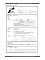
Manual Notices
Manual Notice 2005-1
To:
Users of TxDOT Information Resources
From:
Judy Skeen, P. E., Director,
Information Systems Division
Manual:
TxDOT GPS User’s Manual
Effective Date:
August 1, 2005
Purpose
To provide the Global Positioning Systems (GPS) information governing the operation
standards used by Texas Department of Transportation (TxDOT). These standards are the
policies and guidelines set forth by TxDOT regarding Global Positioning Systems processes
and procedures.
The intent of this manual is for use by TxDOT employees and TxDOT consultants.
Development of this manual provides TxDOT employees and contractors with the concepts,
policies, standards, procedures, and practices that govern Global Positioning System
functions.
Contents
This manual provides information on the use of Global Positioning System (GPS)
technology to perform densification surveys at the State and District level down to smallscale mapping projects. The manual provides an index for quickly locating specific
information in the field. Additionally, Appendix B provides a glossary for definitions of
terms.
Supersedes
The online TxDOT GPS User’s Manual supersedes the TxDOT GPS Manual of Practice,
dated June 2004.
Instructions
Users are encouraged to print this manual double-sided. To ensure manual currency, check
the publishing date of printed manuals against the manual found on the General Services
Division (Online Manuals) website.
Contact
Please address your comments, concerns, or questions regarding this manual’s information
policies, guidelines, procedures, and practices to the TxDOT Standing Committee on
Surveying (SCOS).
Copyright Notice
This manual and this revision:
Copyright © 2005 by Texas Department of Transportation
Published by the Information Systems Division (ISD)
Chapter 1
Introduction
Contents:
Section 1 — Overview.......................................................................................................... 1-2
Section 2 — Chapter Descriptions ....................................................................................... 1-4
GPS User's Manual
1-1
TxDOT 8/2005
Chapter 1 — Introduction
Section 1 — Overview
Section 1
Overview
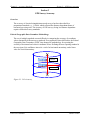
Summary
The TxDOT GPS User’s Manual is referred to as the GPS User’s Manual through all
chapters of this manual. The GPS User’s Manual contains information that governs the
operational standards used by Texas Department of Transportation (TxDOT). These
standards are the policies and guidelines set forth by TxDOT regarding Global Positioning
Systems (GPS) processes and procedures.
Section 2 of this chapter presents all chapter descriptions.
The GPS User’s Manual is primarily intended to be accessed online. The online version
takes precedence over printed copies, changes, updates and edits. However, paper copies
may be used in the field. Copies should be checked for currency date. Caution should be
taken not to rely on the printed version due to ongoing updates and/or changes.
The information within this manual is governed by the laws and standards of information
security. Please refer to the Information Security Manual for specific security information.
Documentation of Authority
The following documents authorize the TxDOT GPS User’s Manual and the activities it
covers:
♦
TxDOT Directive 5-92, TxDOT Manual System
♦
Executive Order 1-89, Policy and Procedures Communication
♦
TxDOT Policy Statement 2-96, Information Security
Laws and Standards
The GPS User’s Manual provides the information that TxDOT GPS and survey resource
users need to comply with applicable legal and policy requirements. Based on federal and
state laws, state standards and agency policy, this manual draws upon the following:
♦
Texas Government Code, Section 2203.004, Requirement to Use State Property for
State Purposes
♦
Texas Government Code, Section 403.275, Liability for Property Loss
GPS User's Manual
1-2
TxDOT 8/2005
Chapter 1 — Introduction
Section 1 — Overview
Purpose of the TxDOT GPS User’s Manual
This manual is intended for use by TxDOT surveyors as well as consultants. This manual
was developed to provide TxDOT employees and contractors with the concepts, policies,
standards, procedures, and practices that govern Global Positioning System (GPS) functions.
It is not the intention of this manual to document all technical procedures used within the
department.
Scope
This manual provides guidance to the surveyor in the use of GPS technology to perform
densification surveys at the state and district level down to small-scale mapping projects. It
sets out the criteria and specifications for TxDOT and consultant surveyors to follow.
Organization of Chapters
Chapters 2-8 are similar in organization and address a general aspect of GPS surveying and
related information. Each chapter has:
♦
a chapter overview
♦
numbered sections for major topics
♦
unnumbered subsections describing concepts and policies relevant to the section topic.
Some chapters also contain procedures with step-by-step directions for successfully
completing tasks related to the section topic.
Subsequent sections are numbered sequentially within each chapter and contain related
information associated with the chapter topic. Each chapter is titled to describe its content.
Subsections contain detailed information that describes concepts, policies, standards, and
procedures related to the section topic. Concepts and policies a user needs to know to
successfully complete a procedure are presented before the procedure, and procedures are
presented in tables with step-by-step (step/action) directions for completing a task.
This manual is designed to be published and accessed electronically. The manual is divided
into an introductory chapter and chapters that address specific GPS topics.
Element
Chapter 1
Chapters 2 – 8
Appendix A
Appendix B
GPS User's Manual
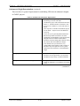
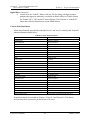
Table 1.1 TxDOT GPS User’s Manual Organization
Purpose
Identifies and provides manual information and organization. Additionally,
it identifies the authorities, laws, and standards that govern the manual.
Provide TxDOT GPS policies and procedures
References
Glossary
1-3
TxDOT 8/2005
Chapter 1 — Introduction
Section 2 — Chapter Descriptions
Section 2
Chapter Descriptions
About this Section
The following subsections describe the contents of Chapters 2-8 of the GPS User’s Manual.
The hyperlinks found in this section will lead the reader to the “Overview” section of a
chapter.
Chapter 2, Background
Chapter 2 provides background on surveying with GPS, including accuracy, error sources,
and the process for handling errors. It presents information on surveying vertical networks
with GPS and the basic differences of conventional and GPS methods.
Chapter 3, Accuracy Standards
Chapter 3 discusses local and network accuracy and provides information on the concepts,
guidelines, standards and specifications, as well as methodologies associated with GPS
survey accuracy standards. Additionally, it provides tables to illustrate coordinate tolerances
and historical accuracy.
Chapter 4, Equipment and Resources
Chapter 4 presents information regarding the use of GPS instruments and equipment. It
includes discussions on the requirements for accurate and consistent data collection for a
variety of instruments and equipment. This chapter also provides information on Internet
resources.
Chapter 5, Network Design
Chapter 5 discusses network design and includes the determination of the number and
location of existing control stations for network constraints, as well as selection of new
project control stations, and relative dispersion of network observations.
GPS User's Manual
1-4
TxDOT 8/2005
Chapter 1 — Introduction
Section 2 — Chapter Descriptions
Chapter 6, GPS Survey Specifications
Chapter 6 covers specifications involved in the planning of a project, field data acquisition
methods, field survey operations and procedures, data processing, analysis of the data, and
documentation. This chapter also provides information on monumentation, survey methods,
field survey operations and procedures, and data processing.
Chapter 7, Units, Data, and Metadata
Chapter 7 provides information regarding the units used in TxDOT work, horizontal and
vertical datum, adjustment factors, requirements for delivering metadata lists and files, and
provisions for conversions and transformations.
Chapter 8, Project Documentation and Deliverables to TxDOT
Chapter 8 TxDOT requirements for project documentation and deliverables are outlined in
this chapter. Specifications on technical reports, digital data; control point data sheets and
validation surveys are presented.
Appendix A, References
Appendix A contains a comprehensive list of references used in the preparation of this
manual.
Appendix B, Glossary
Appendix B contains extensive GPS survey related terms and definitions.
Hyperlinks
Hyperlinks in this manual may appear as red, underlined text or as Web addresses. These
hyperlinks take the reader to related information found within this manual, another manual,
or outside the TxDOT Manual System.
GPS User's Manual
1-5
TxDOT 8/2005
Chapter 1 — Introduction
Section 2 — Chapter Descriptions
How to Get Help
The district survey coordinators are available to answer questions and discuss procedures
and specifications outlined in this manual. Additionally, the Information Systems Division
provides a helpdesk number, which offers survey help from the Automated Survey Support
Unit. Users may access the helpdesk by calling (512) 302-2350, press 3 for engineering
support, and then 4 for surveying support.
As GPS technology advances, changes in the manual will be necessary. If there is a need for
updates or corrections, please notify the district survey coordinator. TxDOT employees will
also be able to find contact information for an area SCOS representative on the intranet Web
site (crossroads) under the miscellaneous link, “TxDOT Surveying and Mapping.”
Printing
Please print double-sided.
Caution: Readers who rely on any printed portions of the manual should check the online
manual regularly for revisions.
GPS User's Manual
1-6
TxDOT 8/2005
Chapter 2
Background
Contents:
Section 1 — Overview.......................................................................................................... 2-2
Section 2 — Surveying with GPS ........................................................................................ 2-3
Section 3 — Surveying Vertical Networks with GPS .......................................................... 2-5
Section 4 — Coordinate Systems ......................................................................................... 2-7
GPS User's Manual
2-1
TxDOT 8/2005
Chapter 2 — Background
Section 1 — Overview
Section 1
Overview
Purpose
The purpose of this chapter is to provide the user with general information regarding the use
of GPS for design grade surveying. Outlined survey processes provide an understanding of
relationships and their components.
GPS User's Manual
2-2
TxDOT 8/2005
Chapter 2 — Background
Section 2 — Surveying with GPS
Section 2
Surveying with GPS
Survey Background Information
All GPS surveying techniques are based upon interferometric observations of radio signals
from a network of orbiting satellites. These signals are processed to compute station
positions by trilateration: the positions of the satellites and computed ranges are used to
determine the antenna position.
These positions are computed in an Earth-centered Earth-Fixed (ECEF) Cartesian coordinate
(x, y, z) system, which can be converted to geodetic curvilinear coordinates (latitude,
longitude, and ellipsoidal height). With the addition of a geoid height model, orthometric
heights can be computed.
Accuracy of a GPS Survey
The accuracy of a GPS survey is dependent upon many complex, interactive factors,
including:
♦
observation technique used, e.g., static vs. kinematic, code vs. phase, etc.
♦
amount and quality of data acquired
♦
GPS signal strength and continuity
♦
ionospheric and tropospheric conditions
♦
station site stability, obstructions, and multipath
♦
satellite orbit used, e.g., predicted vs. precise orbits
♦
satellite geometry, described by the dilution of precision (DOP)
♦
network design, e.g., baseline length and orientation
♦
processing methods used, e.g., double vs. triple differencing, etc.
Error Sources in a GPS Survey
Error sources in a GPS survey include the following:
♦
reference position errors - coordinate, monument stability, crustal motion
♦
antenna position errors - equipment setup, phase center variation and offsets
♦
satellite position errors - orbit ephemeris errors
♦
timing errors - satellite or receiver clock errors
♦
signal path errors - atmospheric delay and refraction, multipath
♦
signal recording errors - receiver noise, cycle-slips
GPS User's Manual
2-3
TxDOT 8/2005
Chapter 2 — Background
Section 2 — Surveying with GPS
♦
human errors - field or office blunders
♦
computing errors - processing and statistical modeling errors.
Operational Procedures
Identify and minimized all errors by redundancy, analysis, and careful operational
procedures including:
♦
the repetition of measurements under independent conditions
♦
make redundant ties to multiple, high-accuracy control stations
♦
ensure geodetic-grade instrumentation, field procedures, and office procedures are used
♦
ensure processing with the most accurate station coordinates, satellite ephemerides, and
atmospheric and antenna models available.
Caution: Be aware that these procedures cannot disclose all problems.
GPS User's Manual
2-4
TxDOT 8/2005
Chapter 2 — Background
Section 3 — Surveying Vertical Networks with GPS
Section 3
Surveying Vertical Networks with GPS
Overview
The use of GPS for vertical network surveys requires an understanding of the relationship
between conventional and GPS height systems, and problems unique to the vertical
component of a GPS measurement.
Conventional trigonometric, spirit, or compensator leveling measures the relative elevations
of points above an undulating equipotential surface called the geoid, which is close to, but
not the same as, “mean sea level.” The model of this undulated geoid surface, currently in
use by TxDOT, is GEOID03. TxDOT uses the NAVD88 vertical datum for orthometric
height (elevation) measurements from this geoid surface (GEOID03) and it has superceded
the old NGVD datum of 1929. Elevations measured by conventional leveling are
orthometric heights.
Ellipsoid Measurements
In contrast, GPS measures the relative heights of points above a smooth, mathematically
simple surface called an ellipsoid. An example of an ellipsoidal reference surface is GRS80,
the defining ellipsoid for NAD 83. Elevations derived from GPS measurements are
ellipsoidal heights minus the separation between the geoid and ellipsoid.
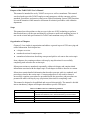
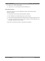
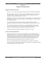
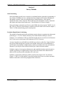
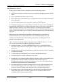
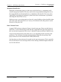
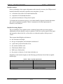
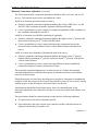
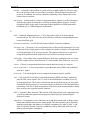
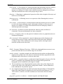
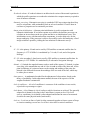
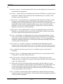
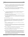
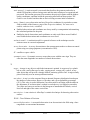
The ellipsoidal (h) and orthometric (H) heights are closely related by the geoid height (N),
the separation between the two reference surfaces, as shown in Figure 2-1 below. Geoid
heights can be derived from GPS observations on bench marks, where both the ellipsoidal
and orthometric heights have been measured for the same point. A network of GPS bench
mark observations, gravity observations, and elevation models are used to develop a geoid
model. From this model, geoid heights at other points in the area can be estimated. The
accuracy of these geoid heights is dependant upon the accuracies of the various
measurements used to construct the model.
Figure 2-1. Relationship between ellipsoidal (h), orthometric (H), and geoid (N) heights.
GPS User's Manual
2-5
TxDOT 8/2005
Chapter 2 — Background
Section 3 — Surveying Vertical Networks with GPS
Note that in the continental United States the ellipsoid is above the geoid; therefore N in
Figure 2-1 is negative. Also, note that the height equation h = H + N is only an
approximation as the orthometric height is measured along a curved plumb line normal to
the geoid surface, while the ellipsoidal and geoid heights are measured along straight lines
normal to the ellipsoid surface. For land surveying applications, the height error associated
with this approximation will always be less than one centimeter.
Height Component
The height component of a GPS survey measurement is also affected by relatively poor
geometric strength for trilateration, as the earth blocks all satellite signals from the
hemisphere below the horizon. This imbalance makes ranging much more critical for
determining vertical. Slight ranging errors from multipath or atmospheric conditions are
more problematic with this poor geometry.
Accordingly, GPS height accuracies for a survey are typically 1½ - 3 times worse than GPS
horizontal accuracies, depending on data quality and baseline length. Increased redundancy
of observations under independent conditions is useful for identifying errors.
Because of the need for four or more vertical control points (and in some cases, all four
quadrants) to establish good GPS elevations, many times it will be more economical to run
conventional level loops.
GPS User's Manual
2-6
TxDOT 8/2005
Chapter 2 — Background
Section 4 — Coordinate Systems
Section 4
Coordinate Systems
Overview
Many spatial activities, such as navigation, mapping, and surveying, use geographic
coordinates to describe the position of objects. Whenever two activities share a common
coordinate system, their data can be more readily compared and exchanged.
For this reason, federal and state mapping products are referenced to two standard
coordinate systems: the North American Datum of 1983 (NAD 83) for horizontal positions
and ellipsoid heights, and the North American Vertical Datum of 1988 (NAVD 88) for
orthometric heights. Surveys are referenced to these datums through measurements to
control points of the National Spatial Reference System (NSRS).
National Spatial Reference System (NSRS) and Continuously Operating Reference Stations
(CORS)
The NSRS is a set of geographic point attributes that provides a consistent framework to
coordinate all spatial activities. The NSRS includes a nationwide network of Continuously
Operating Reference Stations (National CORS), statewide Federal & Cooperative Base
Networks (FBN/CBN), regional User Densification Networks (UDN), and other historic
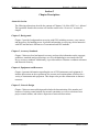
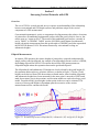
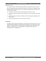
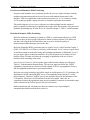
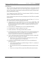
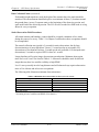
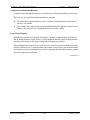
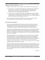
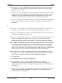
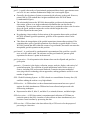
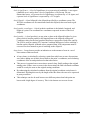
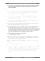
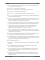
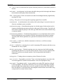
vertical and horizontal control. Figure 2-2 illustrates the CORS Network stations in Texas
and some nearby stations in adjoining states. In Texas, TxDOT operates the majority of
CORS stations.
Cooperative CORS Stations
Also noteworthy is the rapidly growing system of Cooperative CORS stations. Links to the
data from these stations are available on the NGS Web site. Because of the reduced quality
control (QC), limited hours of operation and less permanent nature of these stations, it is
important that the surveyor be thoroughly familiar with those stations in their own area
before depending on them. Also, note that Cooperative CORS coordinates are less accurate
than CORS coordinates.
GPS User's Manual
2-7
TxDOT 8/2005
Chapter 2 — Background
Section 4 — Coordinate Systems
Figure 2-2. CORS Stations.
FBN and CBN
Federal Base Network stations (FBN) (75 to 125 km spacing) or Cooperative Base Network
(CBN) stations (25 to 30 km spacings) are B order accuracy and make up the HARN
network. These HARN stations have been observed using GPS and have been either used
previously as reference stations in the adjustment of the old conventionally surveyed federal
monuments or they are newly placed monuments. There are about four hundred of these
listed by NGS in Texas.
(continued...)
GPS User's Manual
2-8
TxDOT 8/2005
Chapter 2 — Background
Section 4 — Coordinate Systems
FBN and CBN (continued)
This manual uses and/or references specific information from the following publications:
♦
1989 Federal Geodetic Control Subcommittee (FGCS) document “DRAFT Geometric
Geodetic Accuracy Standards and Specifications for Using GPS Relative Positioning
Techniques”
♦
the 1998 NOAA Technical Memorandum “NGS-58, Guidelines for Establishing GPSDerived Ellipsoid Heights,”
♦
the May 15, 2000 “Preliminary DRAFT Guidelines for Geodetic Network Surveys
Using GPS,”
♦
and numerous other federal/state guidelines and specifications listed in Appendix A,
References.
GPS User's Manual
2-9
TxDOT 8/2005
Chapter 3
Accuracy Standards
Contents:
Section 1 — Overview.......................................................................................................... 3-2
Section 2 — GPS Survey Accuracy ..................................................................................... 3-3
Section 3 — Local and Network Accuracy .......................................................................... 3-4
Section 4 — Standards and Specifications ......................................................................... 3-11
GPS User's Manual
3-1
TxDOT 8/2005
Chapter 3 — Accuracy Standards
Section 1 — Overview
Section 1
Overview
Summary
This chapter provides concepts, guidelines and methodologies associated with TxDOT’s
GPS survey accuracy standards. This chapter also contains guidelines intended to assist
users with achieving consistency and accuracy, using GPS dynamic technologies.
GPS User's Manual
3-2
TxDOT 8/2005
Chapter 3 — Accuracy Standards
Section 2 — GPS Survey Accuracy
Section 2
GPS Survey Accuracy
Overview
The accuracy of classical triangulation network surveys has been described by a
proportional standard, e.g., 1:10,000, which reflected the distance-dependant nature of
terrestrial surveying error. The accuracy of GPS surveys, being less distance dependant
requires different accuracy standards.
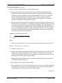
Federal Geographic Data Committee Methodology
The use of multiple standards creates difficulty in comparing the accuracy of coordinate
values obtained by different survey methods. In recognition of these difficulties, the Federal
Geographic Data Committee (FGDC) has changed its methodology for reporting the
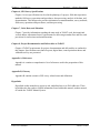
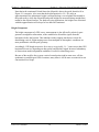
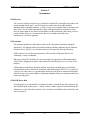
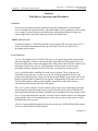
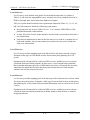
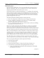
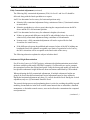
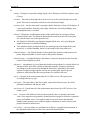
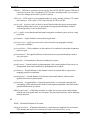
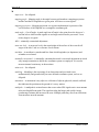
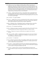
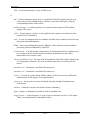
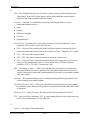
accuracy of horizontal and vertical coordinate values. Defining the new reporting standard is
the two sigma (2σ) confidence intervals: a circle for horizontal uncertainty, and a linear
value for vertical uncertainty.
Vertical
Horizontal
Figure 3-1. 3-D Accuracy
GPS User's Manual
3-3
TxDOT 8/2005
Chapter 3 — Accuracy Standards
Section 3 — Local and Network Accuracy
Section 3
Local and Network Accuracy
Standards
The new standards support both local and network accuracies:
♦
The local accuracy of a control point is a value that represents the uncertainty in the
coordinates of the control point relative to the coordinates of other directly connected,
adjacent control points at the 95-percent (2σ) confidence level.
•
♦
The reported local accuracy is an approximate average of the individual local
accuracy values between a control point and other observed control points used to
establish the coordinates of the control point (i.e. the adjacent stations directly tied
to the control point).
The network accuracy of a control point is a value that represents the uncertainty in the
coordinates of the control point with respect to the geodetic datum at the 95-percent
confidence level.
•
For National Spatial Reference System (NSRS) network accuracy classification,
the datum is considered to be best expressed by the geodetic values at the
Continuously Operating Reference Stations (CORS) supported by NGS. By this
definition, the local and network accuracy values at CORS sites are considered to
be infinitesimal, i.e., to approach zero.
Local accuracy is best adapted to check relations between nearby control points; for
example, a surveyor checking closure between two NSRS points is most interested in a local
accuracy measure.
Positional Tolerance and Associated Coordinates
On the other hand, someone constructing a GIS will often need some type of positional
tolerance associated with a set of coordinates. Network accuracy measures how well
coordinates approach an ideal, error-free datum. The following two tables are reproduced
from National Geodetic Survey’s “Guidelines for Geodetic Network Surveys Using GPS,”
5/15/00 - Preliminary DRAFT.
(continued...)
GPS User's Manual
3-4
TxDOT 8/2005
Chapter 3 — Accuracy Standards
Section 3 — Local and Network Accuracy
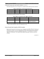
Positional Tolerance and Associated Coordinates (continued)
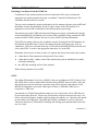
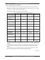
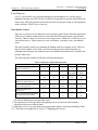
In the following table, the word “Expected” is used because the values given are estimates.
Table 3.1 Expected Survey Accuracies (2σ) for NGS Control
Positional Component
FBN/CBN
UDN
Height (2cm)
Height (5cm)
Horizontal Position
1 cm
various
1 cm
2 cm
Ellipsoidal Height
2 cm
various
2 cm
5 cm
Orthometric Height
3 cm
various
2 cm
5 cm
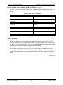
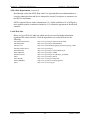
The table below provides positional accuracy history.
Network
NAD27
NAD83
HARN
CORS
Table 3.2 History of Positional Accuracy (2σ) for NGS Control
Time Span
Network Accuracy
Local Accuracy
1927-1986
10 meters
First Order (1:100,000)
1986-1991
1 meter
First Order (1:100,000)
1991-1997
0.1 meter
B Order First Order (1:1,000,000)
A Order (1:10,000,000)
1996-Present 0.01 meter
0.01 meter*
* The best value NGS has; so they are assumed to be zero.
Federal Geodetic Data Committee (FGDC) Standards
Based on the Geospatial Positioning Accuracy Standards, the FGDC-STD-007-1998, Part 2:
Standards for Geodetic Networks prepared by the FGDC, the following accuracy standards
supercede and replace the accuracy standards found in FGCC 1984 and FGCC 1988 (see
Appendix A, References). The classification standard for geodetic networks is based on
accuracy.
(continued...)
GPS User's Manual
3-5
TxDOT 8/2005
Chapter 3 — Accuracy Standards
Section 3 — Local and Network Accuracy
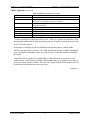
Federal Geodetic Data Committee (FGDC) Standards (continued)
The table of accuracy standards for horizontal, ellipsoid height, and orthometric height is as
follows:
1- Millimeter
2-Millimeter
5-Millimeter
1-Centimeter
2-Centimeter
5-Centimeter
1-Decimeter
2-Decimeter
5-Decimeter
1-Meter
2-Meter
5-Meter
10-Meter
Table 3.3 FGDC Accuracy Standards
Accuracy Classification
95 % Confidence
0.001 meters
0.002 meters
0.005 meters
0.010 meters
0.020 meters
0.050 meters
0.100 meters
0.200 meters
0.500 meters
1.000 meters
2.000 meters
5.000 meters
10.000 meters
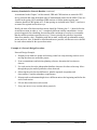
TxDOT Standards
TxDOT has numerous survey accuracy requirements based on the type of project being
surveyed. Listed in the table below are seven levels with typical types of surveys for each.
The level of survey accuracy will be used as a standard throughout this manual to define the
quality of the survey measurements for a particular application.
The seven levels, of course, are of equal or less accuracy than the A and B order federal
monuments, which could be considered Level 0 in the TxDOT scheme. A Level 0 is shown
in some of the charts only to show the relationship of the NGS points to the seven TxDOT
levels.
(continued...)
GPS User's Manual
3-6
TxDOT 8/2005
Chapter 3 — Accuracy Standards
Section 3 — Local and Network Accuracy
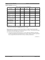
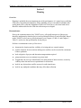
TxDOT Standards (continued)
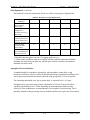
Table 3.4 TxDOT Level of Survey Accuracy
TxDOT Level of Accuracy
Typical Applications
Level 0
CORS, FBN, CBN (this level overseen by NGS)
Level 1
Statewide/district-wide Control Densification, RRP Network Stations (until
recognized as NGS CORS), Cooperative CORS sites
Level 2
Primary Project Control, Control for Airborne GPS for Photogrammetry or
LiDAR Data Gathering
Level 3
Photogrammetric Control Panels, Boundary Corners, ROW, and Local Control
Level 4
Wing Panels for Horizontal Positions*, Topography, Stakeout
Level 5
Sub-meter Mapping for GIS (includes inventory and locative surveys)
Level 6
1 – 5 Meter Mapping for GIS (includes inventory and locative surveys)
Level 7
> 5 Meter Mapping for GIS (includes inventory and locative surveys)
* Vertical positions for wing panels fall in Level 3. However, if panel elevations have been
determined by differential leveling, horizontal positions, if needed, can be determined with
Level 4 GPS observation.
In the interest of keeping its position information integrated properly with the NSRS,
TxDOT will require all new Level 1 (“B” order densification) control, which is established
to be referenced to a minimum of four (4) of the closest A or B order stations surrounding
the station.
Two of these may be publicly accessible FBN or CBN stations but at least two must be
CORS stations. CORS stations, with their downloadable data, are economical to use and are
the most accurate stations available. The ties to the CORS, FBN and CBN stations will serve
as the method to determine the network accuracy.
(continued...)
GPS User's Manual
3-7
TxDOT 8/2005
Chapter 3 — Accuracy Standards
Section 3 — Local and Network Accuracy
TxDOT Standards (continued)
Table 3.5 TxDOT Local Accuracy Classification
Level of Survey
Accuracy *
Local Accuracy Class.
(m)
Base Error (m)
e
Ppm
p
Minimum baseline
length (m)
d
Maximum baseline
length (m)
d
Maximum allowable
error based on minimum
baseline length (m) s
Maximum allowable
error based on maximum
baseline length (m) s
NGS Classification
Range
(See Table 3.7)
Level 0
0.02
Level 1
0.02
Level 2
0.05
Level 3
0.10
Level 4
0.10
0.008
2
10000
0.008
4
3000
0.010
10
400
0.010
20
150
0.010
50
150
20,000
10,000
10,000
5,000
3,000
0.022
0.014
0.011
0.010
0.013
0.041
0.041
0.10
0.10
0.15
VI
VI
VII
VII
VIII
* This table does not apply to mapping grade levels 5, 6 and 7.
Based on the level of survey accuracy listed in Table 3.4, Table 3.5 may be used as the
standard for future classification of surveys performed for TxDOT. The maximum allowable
errors listed on the following page are based on:
♦
All connected and unconnected baselines (vectors) within the minimally constrained
and fully constrained network adjustments must comply with the 3-D relative positional
error (s) required for the desired level of survey accuracy classification.
(continued...)
GPS User's Manual
3-8
TxDOT 8/2005
Chapter 3 — Accuracy Standards
Section 3 — Local and Network Accuracy
TxDOT Standards (continued)
Equation for determining maximum relative positional error at the 95% confidence level:
(
s = e 2 + d × p × 10 −6
)
2
Where,
s = Maximum allowable relative positional error (m) at the 95% (2σ) confidence level
e = Base error in meters (m)
p = Parts per million (ppm)
d = Distance in meters (m)
New NGS GPS Accuracy Standards:
Classification
AA
A
B
First
Second, Class I
Second, Class II
Third
Table 3.6 NGS Accuracy Standards
Minimum Geometric Accuracy Standard at 2 σ
Less than or equal to:
0.003 m + 1:100,000,000
0.005 m + 1:10,000,000
0.008 m + 1:1,000,000
0.010 m + 1:100,000
0.020 m + 1:50,000
0.030 m + 1:20,000
0.050 m + 1:10,000
The following table provides the classification range and confidence levels for accuracy
standards:
Table 3.7 NGS Accuracy Standards for Horizontal Position, Ellipsoid Height, and Orthometric Height
Classification Range
95 % Confidence Level in Meters
Range 0
Reserved for CORS
Range I
< 0.001
Range II
Range III
Range IV
0.001 – 0.002
0.002 – 0.005
0.005 – 0.010
Range V
Range VI
Range VII
0.010 – 0.020
0.020 – 0.050
0.050 – 0.100
(continued...)
GPS User's Manual
3-9
TxDOT 8/2005
Chapter 3 — Accuracy Standards
Section 3 — Local and Network Accuracy
TxDOT Standards(continued)
Table 3.7 NGS Accuracy Standards for Horizontal Position, Ellipsoid Height, and Orthometric Height
Classification Range
95 % Confidence Level in Meters
Range VIII
0.100 – 0.200
Range IX
0.200 – 0.500
Range X
0.500 – 1.000
Range XI
Range XII
Range XIII
Range XIV
1.000 – 2.000
2.000 – 5.000
5.000 – 10.000
> 10.000 **
** Ranges larger than XIII will be developed jointly with other subcommittees within
FGDC.
GPS User's Manual
3-10
TxDOT 8/2005
Chapter 3 — Accuracy Standards
Section 4 — Standards and Specifications
Section 4
Standards and Specifications
Standards and Specifications Issues
There are two issues, which are significant within the manuals’ standards and specifications.
First, least squares analysis is the primary process by which the stated project conclusions
are justified. However, this process is only valid with sufficient redundancy and correct
assumptions made regarding the probability of errors.
Second, the processing of raw GPS observables has been the subject of much innovation and
experimentation. This trend is certain to continue, as GPS technology is extremely dynamic
and changing constantly.
It is the responsibility of the professional in charge to employ techniques, which are
appropriate for the project and to provide verification that the stated conclusions are valid.
The use of these standards and specifications are recommended and do not relieve the
surveyor from making decisions or using professional judgment during the course of the
field survey and the subsequent data processing to obtain the desired results.
Carefully document the procedures, techniques, and results for every step.
Accuracy Levels and Specifications
Experience has shown that current receivers and software have the capability to achieve
geodetic-quality accuracy levels under certain conditions and restrictions. Specifications for
performing control surveys using kinematic techniques require greater observational and
occupational redundancies and checks than usually specified by the manufacturers. The
specifications provide sufficient observational and occupational redundancy to detect
blunders and quantitatively demonstrate accuracy achievement for a survey.
The accuracy reporting requirements of this document are in accordance with accuracy
reporting requirements of the Federal Geographic Data Committee’s “Geospatial Positioning
Accuracy Standards,” FGDC-STD-007-1998.
GPS User's Manual
3-11
TxDOT 8/2005
Chapter 3 — Accuracy Standards
Section 4 — Standards and Specifications
Statistical Analyses
In accordance with new federal positioning standards, these specifications rely heavily on
the use of statistical analyses to determine the accuracy of a GPS survey. Regardless of how
the observations for a particular survey were obtained, the completed survey must provide
the following information:
♦
elimination or reduction of known and potential systematic error sources
♦
sufficient occupational and observational redundancy to clearly demonstrate the stated
accuracy
♦
adequate baseline processing and evaluation, network (least squares) adjustment, and
data evaluation
♦
sufficient documentation to allow verification of the results.
Terminology
In dealing with GPS equipment manufacturers, federal agencies and long time surveyors, we
find phrases and terminology used in different and confusing ways. For the purpose of this
manual, a “GPS observation” is an uninterrupted recording of satellite data at one station
and the created file of raw data. A “GPS session” is a number of observations run
simultaneously for creating baselines.
GPS User's Manual
3-12
TxDOT 8/2005
Chapter 4
Equipment and Resources
Contents:
Section 1 — Overview.......................................................................................................... 4-2
Section 2 — Instruments ...................................................................................................... 4-3
Section 3 — Internet Resources ........................................................................................... 4-6
GPS User's Manual
4-1
TxDOT 8/2005
Chapter 4 — Equipment and Resources
Section 1 — Overview
Section 1
Overview
Summary
This chapter presents valuable information regarding the use of GPS instruments and
equipment. It includes discussions on the requirements for accurate and consistent data
collection for a variety of instruments and equipment. Basic instrumentation for TxDOT
GPS control surveys includes multiple sets of receivers, antennas, and fixed-height and/or
variable height tripods. To minimize equipment biases, use of identical equipment is
encouraged whenever possible.
GPS User's Manual
4-2
TxDOT 8/2005
Chapter 4 — Equipment and Resources
Section 2 — Instruments
Section 2
Instruments
GPS Receiver
The receivers used for network surveys should record the full-wavelength carrier phase and
signal strength of both the L1 and L2 frequencies, and track at least eight satellites
simultaneously on parallel channels. L1 only receivers are acceptable only for baselines less
than 10 km. Ties to CORS sites should be made with dual-frequency instruments if base
lines are longer than 10 km. Receivers should have sufficient memory and battery power to
record 6-hours of data at 5-second epochs. Receivers should contain the latest
manufacturer’s firmware upgrades.
GPS Antenna
The antennas should have stable phase centers and be designed to minimize multipath
interference. All antenna models used should undergo antenna calibration by the National
Geodetic Survey (NGS). Users should consult user’s manual for other specifications.
NGS Geodetic Services Division maintains a GPS Antenna Calibration Web site for
calibrating a variety of antennas.
When processing GPS baselines, the user must apply the appropriate GPS antenna phase
center offsets. Inappropriate phase center offsets can introduce up to 10 cm of error in the
baseline.
GPS antenna ground planes should be utilized according to manufacturer specifications.
Ground planes must be utilized for all stations when performing TxDOT Level 1 and Level
2 surveys. For other surveys, a ground plane must be used at the base station and should be
utilized in areas where there might be significant multipath. Many new antenna models have
built in ground planes.
GPS-RTK Rover Rod
A fixed height rover rod should be used and if possible, it should be the same height as any
fixed height tripods on the project – usually 2-meters. Make a physical measurement in the
field notes to verify it has been checked. Also, check the level bubble on the rod before and
after each project.
GPS User's Manual
4-3
TxDOT 8/2005
Chapter 4 — Equipment and Resources
Section 2 — Instruments
Tripods
The tripods must facilitate precise offset measurements between the mark datum point and
the antenna reference point (ARP). Fixed-height rods or fixed height tripods are preferable
and required for certain surveys due to the decreased potential for antenna centering and
height measurement errors. All tripods should be examined for stability with each use.
Ensure that hinges, clamps, and feet are secure and in good repair. Test the fixed-height
tripods for stability, plumb alignment, and height verification at the start and end of each
project.
Tribrachs
Tribrachs and rod levels should be field calibrated before use on each project and should be
checked at the end of the project. Any data not bracketed by a successful calibration check
are suspect. Professional Tribrach calibration, usually scheduled once a year with regular
use is a reasonable interval for maintaining the accuracy of the instrument.
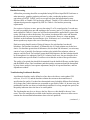
Instrumentation Requirements
Summarized below are instrumentation and data collection requirements:
Level of Survey *
GPS Receivers
Dual Frequency
Single Frequency
GPS antennas
Tripods
3d ant. H.I. and centering
pos. tolerance
Minimum # of GPS
receivers**
RTK acceptable
Table 4.1 Instrumentation Requirements
Level 0
Level 1
Level 2
Required
Not
Acceptable
Ground plane
Required
Required
Not
Acceptable
Ground plane
Required
Fixed H.I.
Required
0.2 cm
Required
Not
Acceptable
Ground
plane
Required
Fixed H.I.
or Variable
0.2 cm
3
No
Level 3
Level 4
Recommended Recommended
Acceptable
Acceptable
Ground plane
Optional
Ground plane
Optional
Fixed H.I. or
Variable
0.3 cm
Fixed H.I. or
Variable
0.4 cm
Fixed H.I. or
Variable
0.4 cm
3
2
2
2
No
No
No***
Yes
* This chart does not apply to mapping level surveys Levels 5, 6 and 7.
** Minimum # of receivers simultaneously logging data during a session not including
CORS.
*** Acceptable if points are located from more than one control point at different times.
GPS User's Manual
4-4
TxDOT 8/2005
Chapter 4 — Equipment and Resources
Section 2 — Instruments
Personnel
All field personnel should be trained in the avoidance of systematic errors during field
operations. Field personnel often work alone and must be prepared to make wise, on-thespot decisions regarding mark identification and stability, equipment use and
troubleshooting, and antenna setup. Office personnel should be familiar with geodetic
concepts and least squares adjustments. Personnel should participate in any available
certification and training activities.
All boundary control survey projects performed for TxDOT will be performed under charge
of a Texas Registered Professional Land Surveyor (RPLS). Personnel requirements for
various types of surveys may vary from one TxDOT district to another. The use of certified
survey technicians (CST’s) is encouraged not to fulfill any requirements, but to aid in the
efficiency of operations with the use of goal-oriented employees.
GPS User's Manual
4-5
TxDOT 8/2005
Chapter 4 — Equipment and Resources
Section 3 — Internet Resources
Section 3
Internet Resources
The CORS Site
Using the CORS reference stations insures that all project control points are on a recognized
network. It may not seem important at the time, but it also puts the TxDOT project on the
NSRS at no extra cost. In fact, it saves sending extra people to the field and buying or
renting extra GPS receivers.
For the extra few minutes it takes to download data, the office technician may as well
include several additional CORS stations beyond the one or two required by the
specifications. Refer to Figure 2-2 for a map of CORS stations as of this writing or visit the
NGS Web site www.ngs.noaa.gov under the CORS/OPUS heading for an all-inclusive and
current map.
Retrieving Data from the CORS Site
Retrieve CORS data from NGS from the NGS Web site at: www.ngs.noaa.gov/CORS.
The User Friendly CORS site (UFCORS) allows the user to download all the data desired in
just one file containing the number of hours needed from a start time entered on the online
form and, at the user’s request, can include the coordinates and ephemeris in one simple
zipped download. It is not necessary to convert to Universal Time Coordinate (UTC) time or
sort through the coded file names. All files available from NGS are in RINEX format.
Should users need to use individual hourly files, a typical NGS RINEX data file from a
CORS station appears with this naming convention: {SSSS} {DDD} {H} . {YY} {T}
Where SSSS is the four (4)-character site identifier:
DDD is the day of year
H is a letter that corresponds to an hour-long UTC time block
YY is the year
T is the file type
Example: txan3350.01o
For daily files, the format would be {SSSS}{DDD}{H}0.{YY}{T}.
GPS User's Manual
4-6
TxDOT 8/2005
Chapter 4 — Equipment and Resources
Section 3 — Internet Resources
Obtaining Coordinates from the CORS Site
Coordinates for the station needed can also be found on the Web site by clicking the
appropriate site on the map then choosing “coordinates” from the left hand menu. The
coordinate data sheet has two sections.
The top section contains the position information for the antenna reference point (ARP) and
the bottom section, the information for the L1 phase center of the GPS antenna. It is
important to use the ARP coordinates for the held position in processing.
The antenna type at the CORS station (needed during processing) is included in the header
of the downloaded file. In addition, each section of the coordinate listing contains the ITRF
position and the NAD83 position. Be sure to use the NAD83 position information.
If the PID of a station is known, the coordinates can also be found in the NGS database for
the National Spatial Reference System. By starting from the NGS home page, click on
“datasheets” in the five selections at the top. Click on the DATASHEETS retrieval link and
click on the PIDs. To retrieve the appropriate data sheet, key in the PID.
Remember, there may be as many as three (3) separate data sheets associated with a station:
♦
a data sheet for the monument on the ground (if one exists)
♦
a data sheet for the L1 phase center of the antenna (the point at which data is actually
collected) and finally,
♦
the ARP (the mounting surface of the antenna).
Each of these points has its own PID.
OPUS
The Online Positioning User Service (OPUS) is the newest addition to NGS’ Geodetic Tool
Kit. OPUS allows users to submit their GPS data files in RINEX format to NGS, where the
data will be processed to determine a position using NGS computers and software. Each
RINEX file submitted is processed with respect to three (3) National CORS sites or
Cooperative CORS sites.
Any stations in a TxDOT network that contain two (2) or more hours of raw GPS data can
be processed at this Web site. The tie sites selected may not be the nearest to the users’ site
but are selected by distance, number of observations, site stability, etc. Users have the option
to select their own CORS sites. The ITRF and NAD83 coordinates, as well as Universal
Transverse Mercator (UTM) and SPC Northing and Easting report position data back to the
user via e-mail.
(continued...)
GPS User's Manual
4-7
TxDOT 8/2005
Chapter 4 — Equipment and Resources
Section 3 — Internet Resources
OPUS (continued)
TxDOT recommends that users check the results of the processing and adjustment on new
points with this NGS service. As a minimum, at least one station should be checked in every
network. OPUS positions are usually within one or two tenths of a foot. However, they may
be less precise in areas of one-direction-only ties.
Use this to verify the NAD83 HARN position and ellipsoid height. Orthometric heights may
not tie, based on whether the elevation was established before or after the original Texas
HARN network was created.
NGS Description of OPUS
The National Geodetic Survey operates the Online Positioning User Service (OPUS) as a
means to provide GPS its user’s easier access to the National Spatial Reference System
(NSRS).
OPUS allows users to submit their GPS data files in RINEX format to NGS, where the data
is processed to determine a position using NGS computers and software. Each RINEX file
submitted is processed with respect to three (3) CORS sites.
The sites selected may not be the nearest to the users’ site but are selected by distance,
number of observations, site stability, etc. Users have the option to select their own CORS
sites. The position for data will be reported back to the user via e-mail in both ITRF and
NAD83 coordinates, as well as UTM and SPC Northing and Easting coordinates.
NGS OPUS Requirements
OPUS is completely automatic. Users are required to enter only a minimal amount of
information. OPUS requires the following:
♦
e-mail address to receive results
♦
RINEX file that the user wants to process (which may be selected using the browse
feature)
♦
antenna type used to collect this RINEX file (selected from a list of calibrated GPS
antennas)
♦
height of the Antenna Reference Point (ARP) above the monument or mark that user is
positioning
♦
as an option, users may also enter the state plane coordinate code if they want SPC
Northing and Easting.
Once the information is completed, click the upload button to send the data to NGS. User’s
results will be e-mailed in a few minutes. Upload one RINEX file at a time.
(continued...)
GPS User's Manual
4-8
TxDOT 8/2005
Chapter 4 — Equipment and Resources
Section 3 — Internet Resources
NGS OPUS Requirements (continued)
Read through each of the OPUS Help Links. It is important that users understand how to
correctly submit their data and how to interpret the results. For inquires or comments, use
the OPUS e-mail button.
OPUS is intended for use in the conterminous U.S., Alaska, and Hawaii. It is NGS policy
not to publish geodetic coordinates outside the U.S. without the agreement of the affected
countries.
Useful Web Sites
Below is a list of Web site addresses which may be accessed for further information
regarding GPS-related activities. Click the hyperlink to access the Web site for the
following:
GPS Antenna Information
GPS Orbital Data
GPS Overview
National Geodetic Survey
NGS Data Sheets
NGS CORS Data
NGS PC Software
OPUS
Space Weather
TxDOT RRP Data
USCG
GPS User's Manual
http://www.ngs.noaa.gov/ANTCAL/index.shtml
http://www.ngs.noaa.gov/GPS/GPS.html
http://www.colorado.edu/geography/gcraft/notes/gps/gps_f.html
http://www.ngs.noaa.gov/
http://www.ngs.noaa.gov/cgi-bin/datasheet.prl
http://www.ngs.noaa.gov/CORS/
http://www.ngs.noaa.gov/PC_PROD/pc_prod.shtml
http://www.ngs.noaa.gov/OPUS/
http://www.sec.noaa.gov/today.html
http://www.dot.state.tx.us/isd/gps/gps.htm
http://www.navcen.uscg.gov/
4-9
TxDOT 8/2005
Chapter 4 — Equipment and Resources
Section 3 — Internet Resources
Retrieving Data from TxDOT
Retrieving CORS data from the original TxDOT maintained stations (RPS’s) can be done
from the Internet using the following TxDOT Web address:
http://www.dot.state.tx.us/isd/gps/gps.htm.
TxDOT posts files in both RINEX and Trimble formats. RINEX file naming convention is
standard but a TxDOT data file in Trimble format will have a different naming convention.
TxDOT is in the transition of updating the GPS data distribution web page. The
“FileFormat.txt” file included on the Web site will contain the latest information for naming
convention and the “Position_update.doc” contains the original TxDOT coordinates as well
as antenna heights (for use of the actual monument rather than the ARP). Always refer to
these documents when processing data from the TxDOT Web site.
Files in Trimble format are available in six (6) hour increments or four (4) files per day and
files in RINEX format are available hourly. Note that Julian dates are based on Universal
Time Coordinate (UTC). The is no provision for combining files before download. Data is
kept for six (6) months and data older than six (6) months must be retrieved from NGS.
If all the CORS reference stations in the network the user is building are original TxDOT
RRP’S, and if users have need for maintaining the TxDOT position used in the mid 1990’s,
TxDOT still adjusts some of the newer RRP’s to the original unchanged coordinates of that
time and makes them available on the “Position_update.doc” file above. Some RRP location
at the outer edges of the state may differ from the NGS positions (epoch 2002) by a couple
of centimeters. Remember to us H.I.’s when holding the actual monument rather than the
usual ARP position. Also, note that these H.I.’s are to the phase center of the antenna.
GPS User's Manual
4-10
TxDOT 8/2005
Chapter 5
Network Design
Contents:
Section 1 — Overview.......................................................................................................... 5-2
Section 2 — Design Features ............................................................................................... 5-3
GPS User's Manual
5-1
TxDOT 8/2005
Chapter 5 — Network Design
Section 1 — Overview
Section 1
Overview
Summary
Network design includes: 1.) the determination of the number and location of existing
control stations for network constraints; 2.) the selection of new project control stations, and
3.) the relative dispersion of network observations.
Network design has relevance for concerns regarding the elimination and/or reduction of
potential error sources, as well as for providing adequate ties to the existing geodetic
reference system (NAD83). These concerns may be addressed by the choice of which
existing control stations should be included, as well as the planning of the new station
locations and network observation periods. GPS derived orthometric heights are particularly
sensitive to the distribution of observations and network constraints.
GPS User's Manual
5-2
TxDOT 8/2005
Chapter 5 — Network Design
Section 2 — Design Features
Section 2
Design Features
Control
To meet a network or local accuracy level, a GPS project must be connected to sufficiently
accurate and well-distributed existing control.
All of the control stations to which the network will be constrained must have positions
known on the NAD83 datum. Control stations of the state HARN adjustment are generally
used; however, certain special projects may have a legitimate need for another geodetic
reference. Use the appropriate datum adjustment as recommended by the TxDOT district
surveyor or survey coordinator.
The minimum number of horizontal and vertical constraints is stated in Table 5.1, with their
location being distributed in different quadrants relative to the center of the project. Where
existing NGS or TxDOT horizontal and/or vertical control on a common datum and epoch is
available, all such stations lying within a few kilometers of the survey’s boundaries should,
if possible, be included in the survey if they meet the horizontal accuracy requirements.
Second order or better is generally required for vertical.
Orthometric Height
Requirements for orthometric height constraints are dependent upon geoid slope, project
extent, desired accuracy, and the density of the gravity database. These issues are addressed
under the subsection, Orthometric Height Determination in Chapter 6, Section 7.
In general, vertical control for Level 1 and Level 2 networks require a minimum of 4,
preferably 5 published vertical control stations. They should be situated on the outside
corners of the project at a minimum.
In other words, at least one bench mark should be fixed in each of the four (4) quadrants of
the survey area, such that nearly all of the newly surveyed stations will fall inside a
boundary drawn around the outside benchmarks. Additional benchmarks inside the
perimeter will aid in strengthening the adjustment.
GPS User's Manual
5-3
TxDOT 8/2005
Chapter 5 — Network Design
Section 2 — Design Features
Network Baseline
TxDOT recognizes there are arguments for and against the use of dependent (trivial)
baselines in a network. TxDOT recommends not using dependent baselines.
For any given multiple receiver session, there are n(n-1)/2 total vectors possible, where n =
the number of GPS receivers observing simultaneously. The number of independent vectors
is n-1.
Using only the independent baselines:
♦ prevents adjusting the same observations more than once and misstating the network
degrees of freedom in the least squares adjustment
♦ makes it easier to troubleshoot and evaluate the network and locate deviant baselines.
GPS User's Manual
5-4
TxDOT 8/2005
Chapter 5 — Network Design
Section 2 — Design Features
Accuracy Standards for Network Baseline
For a station to qualify for an accuracy classification, network or local, it must meet the
listed accuracy standards, relative to all other stations in the network and/or datum, whether
or not there was a direct connection between them.
The table below outlines requirements for network design.
Table 5.1 Minimum TxDOT Network Design Specifications
Level of Accuracy *
Level 0
Level 1
Level 2
Minimum Number of
2
2
1
Closest Direct CORS Ties
Minimum Number of
4
4
3
Total FBN/CBN /CORS
Station Ties
Minimum Number of
4
4
3
Horizontal Station Ties
(Level 0 ties)
(Level 1 or 0)
Minimum Number of
6
5
4
Vertical Ties (2nd order or
better)
Minimum Number of
2
2
2
Occupations Per Station
Minimum Number of
50%
40%
30%
Repeat BL’s (% of all
BL’s)
Time Offset Between
± 4 hrs
± 3 hrs
± 2 hrs
Observations
(Occupations ***)
Minimum Satellite
15 Degrees
15 Degrees
13 Degrees
Elevation Mask
Minimum Number of
4
4
3
Quadrants for H Station
Ties
Minimum Number of
4
4
4
Quadrants for V Station
Ties
Type of Ephemeris
precise
precise
rapid or precise
Required
Level 3
0
2**
2
(Level 0,1, or 2)
2
2
20%
± 1 hr
13 Degrees
2
2
broadcast
or better
* Level 4, 5, 6 and 7 surveys are generally not network surveys – network requirements do
not apply
** These should be at least be indirect ties to CORS, FBN or CBN stations – they may be
surveyed from Level 2 stations, which have been directly tied to CORS, FBN or CBN
stations
*** To qualify for a new occupation, the observer must remove the GPS receiver at the
station and a completely new setup over that station must take place.
(continued...)
GPS User's Manual
5-5
TxDOT 8/2005
Chapter 5 — Network Design
Section 2 — Design Features
Accuracy Standards for Network Baseline (continued)
As mentioned in the Chapter 3 of this manual, FBN and CBN stations are statewide GPS
survey networks that form the highest order of monumented control for the NSRS. These are
A and B order points. NGS-maintained FBN stations at 100 km station spacing and
volunteer-densified CBN points at 25-50 km spacing are included in the Table 5.1 and serve
as control for regional and local surveys.
Ideally, the time offset between observations should be 24 hours plus 3 – 9 hours before the
second observation in order to “see” a completely different satellite constellation. A more
practical approach for scheduling observations with a minimum of overlap is to remember
that the satellite positions repeat about every 12 hours (actually they advance in position
about four minutes a day). Scheduling with this in mind, could result in substantial savings
in time and cost. Also, it should be noted that whenever possible, a different receiver should
be used at that station for the repeat observation.
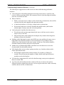
Example of a Network Design Procedure
Network Design Example:
1.
Roughly locate both new points and existing control on a map showing roads to use in
moving the observers around the project.
2.
From reconnaissance and mission planning software, determine the best times to
observe.
3.
For each session, draw the independent baselines chosen to be observed on map. Move
through the project until all points have been observed.
4.
Observing the rules for time differences, plan the repeated occupations and
observations. Consider redundancy requirements.
5.
Measure and record antenna height in two different units at the beginning and before the
end of each session.
6.
Fill out observation sheet each session.
7.
Every one moves every session (where practical).
GPS User's Manual
5-6
TxDOT 8/2005
Chapter 6
GPS Survey Specification
Contents:
Section 1 — Overview.......................................................................................................... 6-2
Section 2 — Specifications................................................................................................... 6-3
Section 3 — Planning ........................................................................................................... 6-4
Section 4 — Monumentation.............................................................................................. 6-11
Section 5 — Survey Methods ............................................................................................. 6-12
Section 6 — Field Survey Operations and Procedures....................................................... 6-14
Section 7 — Data Processing ............................................................................................. 6-29
GPS User's Manual
6-1
TxDOT 8/2005
Chapter 6 — GPS Survey Specification
Section 1 — Overview
Section 1
Overview
Scope
The specifications outlined in this chapter cover the planning of the project, field data
acquisition methods, field survey operations and procedures, monumentation, survey
methods, data processing, analysis of the data, and documentation.
The uses of these specifications, along with the manufacturer’s specifications, provide a
means for the surveyor to evaluate the survey and to verify the specified accuracy standard
achievement.
GPS User's Manual
6-2
TxDOT 8/2005
Chapter 6 — GPS Survey Specification
Section 2 — Specifications
Section 2
Specifications
Overview
The specifications within this chapter ensure that a survey performed with GPS technology
is repeatable, meets accuracy requirements, and referenced to the National Spatial Reference
System (NSRS) by providing the following:
♦
elimination or reduction of known and potential systematic error sources
♦
occupational (station) and observational (baseline) redundancy to clearly demonstrate
the stated accuracy
♦
baseline processing, data adjustment and data analysis to clearly demonstrate the stated
accuracy
♦
documentation demonstrating verification of the results.
GPS survey specifications continually evolve with the advancements in equipment and
techniques. Changes to these specifications are expected as these advancements occur. The
size, scope, and site conditions of a project may also require variations from these
specifications.
Remember, any variations from these specifications should be designed to meet the above
criteria and to achieve the accuracy standard of the survey; as required by this manual. All
variations must be pre-approved by TxDOT and documented in the project report.
GPS User's Manual
6-3
TxDOT 8/2005
Chapter 6 — GPS Survey Specification
Section 3 — Planning
Section 3
Planning
Overview
Planning is probably the most important part of the performance of a control survey utilizing
GPS survey measurement techniques. Proper planning will give one added confidence that
quality data will be collected. Regardless of the level of the survey, the items listed below
should be addressed before the field data collection process begins.
Reconnaissance
Prior to the commencement of any TxDOT survey, all significant aspects of the project
should be understood so that the project can be performed effectively and efficiently. Based
on the TxDOT level of survey to be performed, go to Chapter 4, Table 4.1 and Chapter 5,
Table 5.1 and review the specifications for the project.
Perform a reconnaissance survey of the site to:
♦
determine the location and sky visibility of existing and new control stations
♦
pick the locations for new stations making sure satellites can be recorded in a minimum
of three quadrants
♦
look at logistics of project and determine transportation required
♦
gain permission to access station(s) on private land
♦
if applicable, the surveyor should notify law enforcement of their activities; record sky
visibility chart data and access requirements for all stations
♦
look for any objects that could be sources for radio interference
♦
look for any multipath conditions that may affect data collection.
GPS User's Manual
6-4
TxDOT 8/2005
Chapter 6 — GPS Survey Specification
Section 3 — Planning
Monumentation for New Stations
All monumentation for new Level 1 points are to be in accordance with the following NGS
publications.
Concrete Marks, from NGS Operations Handbook and Manual of Geodetic Triangulation,
S.P. 247
Setting a Survey Disk in Bedrock or a Structure from NOAA Manual NOS, NGS 1,
Geodetic Bench Marks
Setting a NGS 3-D Monument Based on Revised NGS 3-Dimensional (3-D) Rod Mark
[Draft Version] by: Curtis L. Smith, National Geodetic Survey, July, 1996
It is recommended that new Level 2 points also follow these construction specifications, but
the TxDOT surveyor in charge may call for less stringent requirements.
Naming Convention for Level 1 and Level 2 Monuments
The recommended naming convention for Level 1 and Level 2 monuments is as follows:
Example: 1580032
Digits
158
0032
♦
♦
♦
♦
Table 6.1 Naming Convention
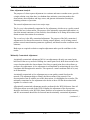
Indication
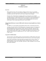
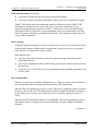
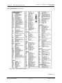
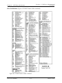
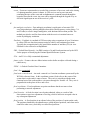
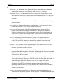
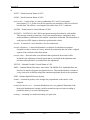
The first three (3) digits indicate the county in which the monument was set.
This is the standard county code used by TxDOT (see Figure 6-5, 6-6).
The next four digits indicate the point number of this particular monument.
It is specific for this county and there can be no duplicates in the county.
Some districts use variations of this by including a prefix or suffix.
Figure 6-2 and Figure 6-3 are sample data sheets for documenting the monuments likely to
be used in the future. There must be a data sheet for all Level 1 and Level 2 monuments.
Districts may use their own data sheet form, but it must contain all the horizontal and
vertical geodetic data of this sample data sheets. An RPLS signature and seal is
recommended for data sheets for Level 1 and Level 2 GPS monuments.
GPS User's Manual
6-5
TxDOT 8/2005
Chapter 6 — GPS Survey Specification
Section 3 — Planning
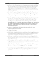
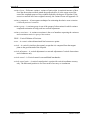
Figure 6-1. List of the standard county designator codes used by TxDOT.
GPS User's Manual
6-6
TxDOT 8/2005
Chapter 6 — GPS Survey Specification
Section 3 — Planning
Control Point Data Sheet Form
Figure 6-2. TxDOT Control Point Data Sheet.
GPS User's Manual
6-7
TxDOT 8/2005
Chapter 6 — GPS Survey Specification
Section 3 — Planning
GPS Control Point
Figure 6-3. Sample project specifications control point.
GPS User's Manual
6-8
TxDOT 8/2005
Chapter 6 — GPS Survey Specification
Section 3 — Planning
Satellite Health and Availability
Only healthy satellites should be observed during the course of data collection. The satellite
health situation can be checked by accessing the latest GPS status message from the USCG
web site at http://www.navcen.uscg.gov/. This status message can also determine if there
were problems after the data collection period is over.
There are times of the day when the numbers of satellites available will vary. Especially
with real-time kinematic (RTK) positioning planning a work around for these times greatly
increases productivity and the quality of results. Most, if not all, GPS software packages
include a utility allowing the user to predict satellite coverage. A minimum of five (5)
satellites are to be logged for any GPS work. In order to project satellite availability, the
software will require a recent ephemeris file.
One internet site for obtaining this file is:
http://www.trimble.com/planningsoftware_ts.asp?Nav=Collection-8425
Sky Visibility
Prior to data collection, the surveyor should look at each station to determine the extent, if
any, of sky visibility obstructions greater than ten (10) degrees above the horizon. This
survey should include obstructions in all four (4) quadrants of the sky.
If there are obstructions, the most desirable place for those obstructions to be located is
northward of the station to be surveyed because of the design of the satellite constellation. If
there is an obstruction in that area, it could still be a source of multipath at the GPS antenna.
Therefore, the obstruction should be located.
Satellite Geometry
The geometric quality of a constellation of satellites is measured by
Position Dilution of Precision (PDOP). It is also measured by
Geometric Dilution of Precision (GDOP). The difference between PDOP and GDOP is that
GDOP considers time, where PDOP only considers geometry.
The user should be aware of the manufacturer’s recommendations of maximum DOP values
for the various types of surveys the user will perform. The vertical component of the GPS
position is the most likely component to lack in quality if the DOP values are high.
Therefore, if performing a vertical control survey, collect data with conservative DOP
values.
(continued...)
GPS User's Manual
6-9
TxDOT 8/2005
Chapter 6 — GPS Survey Specification
Section 3 — Planning
Satellite Geometry (continued)
One way to ensure that quality data are collected for the vertical is to collect satellite data
that includes at least one satellite that is tracked greater than seventy (70) degrees above the
horizon. However, a VDOP of less than 4.0 is all that is required. A PDOP of over 6.0
should probably be considered to be too great for usable data, making a PDOP of over 7.0 is
unacceptable. Static data during periods of high DOP values should be deleted. Performance
of RTK is more demanding and should not be done at PDOP values of 4 or greater.
Space Weather Considerations
A highly active ionosphere can have more severe implications for GPS observations.
Magnetic storms and solar radiation storms will affect the signal-to-noise ratio (SNR) and
may cause initialization problems with real-time kinematic (RTK) positioning and noisy
data in static observations.
One measure of space weather activity is the scale developed by NOAA. Their Web site
address, www.sec.noaa.gov/NOAAscales/, will predict activity on a scale of 1 to 5 with
anything above 1 (one) becoming a hindrance to quality data collection.
The Costello Geomagnetic Index charts are found at http://www.sec.noaa.gov/rpc/costello/
Kp index of five (5) or more may cause problems and GPS surveying should not be done at
six (6) or above. RTK should not be done at a Kp index of five (5) or greater.
GPS User's Manual
6-10
TxDOT 8/2005
Chapter 6 — GPS Survey Specification
Section 4 — Monumentation
Section 4
Monumentation
Overview
The knowledge of important considerations, which ensure the stability and continued
usability of monuments, is vital to successful monumentation. The references to procedures
and guidelines presented within this section aid the user in properly establishing a GPS
survey monument.
Monumentation Guidelines
For monumentation guidelines, refer to Appendix A of this manual or the National Geodetic
Web site at http://www.ngs.noaa.gov/.
GPS User's Manual
6-11
TxDOT 8/2005
Chapter 6 — GPS Survey Specification
Section 5 — Survey Methods
Section 5
Survey Methods
Static Positioning
Static positioning typically uses a network or a multiple baseline approach for positioning. It
may consist of multiple receivers, multiple baselines, multiple observational redundancies
and multiple sessions. After processing the data to obtain baselines, a least squares
adjustment of the results is required. This method provides the highest accuracy achievable
and requires the longest observation times – from an hour to five hours or longer.
Static positioning is primarily used for ties to the NSRS when observing for TxDOT Level 1
and 2 surveys. However, this technique could be used for the other levels listed in Chapter 3,
Table 3.4 of this manual using project control points.
FastStatic (Rapid Static) Positioning
The method of faststatic/rapid static positioning requires shorter occupation times than static
positioning (i.e. 15 to 20+ minutes) and may use a radial baseline technique, network
technique, or a combination of the two. Baseline lengths may not exceed ten (10) kilometers
for L1 only receivers and twenty (20) kilometers for L1/L2 receivers.
Accuracy degrades at a predictable rate with this type of survey; therefore, longer baselines
may be used when design survey quality is not needed. Please refer to the manufacturer’s
specifications for minimum occupation times, number of satellites observed, and minimum
amount of cycle slip free data collected for this type of data collection method.
FastStatic requires a least squares adjustment or other multiple baseline statistical analysis
capable of producing a weighted mean average of the observations. More than one base
station will be used to provide redundancy for each vector.
FastStatic or rapid static techniques could be used for observing Levels 3 & 4 listed in
Chapter 3, Table 3.4 of this manual. It provides baselines that do not exceed the maximum
distances stated above in the first paragraph of this subsection.
GPS User's Manual
6-12
TxDOT 8/2005
Chapter 6 — GPS Survey Specification
Section 5 — Survey Methods
Post-Processed Kinematic (PPK) Positioning
Post-processed kinematic survey methods provide the surveyor with a technique for high
production measurements and can be used in areas with minimal obstructions of the
satellites. PPK uses significantly reduced observation times (i.e. 0.5 to 3 minutes, usually
10-30 seconds per point) compared to static or faststatic/rapid static observations.
This method requires a least squares adjustment or other multiple baseline statistical
analysis capable of producing a weighted mean average of the observations. Post-processed
kinematic positioning may be used for Level 4 listed in Chapter 3, Table 3.4 of this manual.
Real-time Kinematic (RTK) Positioning
Real-time kinematic positioning is similar to a PPK or a total station radial survey. RTK
does not require post processing of the data to obtain a position solution. This allows for
real-time surveying in the field and allows the surveyor to check the quality of
measurements without having to process the data.
Real-time kinematic (RTK) positioning may be used for Levels 3 and 4 listed in Chapter 3,
(Table 3.4 TxDOT Level of Survey Accuracy) of this manual. Level 3 surveys require that a
second observation be made after losing and regaining initialization. Additionally, Level 3
surveys require that a second base station be set up for the purpose of creating a second
baseline. Most GPS units will allow the averaging or adjustment of the two or more
baselines while remaining at the point.
Level 4 surveys; however, will accept the single radial baseline solution (see Chapter 4,
Table 4.1, Instrumentation Requirements). The surveyor must also follow the TxDOT
redundancy requirements (see Section 6 of this chapter, RTK for Topographical Surveys)
and the equipment manufacturer’s prescribed methods.
Real-time surveying technology may utilize single or dual-frequency (L1/L2) techniques for
initialization, but the subsequent RTK survey is accomplished using only the L1 carrier
phase frequency. Therefore, all RTK surveys are currently subject to the limitations of the
L1 frequency, which is ten (10) kilometers from the base station. There may be
circumstances where this maximum range may be extended. Permission to extend this range
will be extended at the TxDOT project surveyor’s discretion.
Radio transmission and cell phones are the most common way of providing the
communication link between the base and rover.
GPS User's Manual
6-13
TxDOT 8/2005
Section 6 — Field Survey Operations and
Procedures
Chapter 6 — GPS Survey Specification
Section 6
Field Survey Operations and Procedures
Overview
Field survey operations should be performed using the manufacturer’s recommended
receiver settings and observation times. Operations under adverse conditions, such as under
a tree canopy or around urban environments where multipath conditions are high, may
require longer observation times than specified by the manufacturer.
TxDOT Survey Levels
As noted in Chapter 3, TxDOT has divided its design grade GPS surveying into seven (7)
levels to facilitate understanding of the type and scope of the survey, and to aid in
developing specifications.
Level 1 Surveys
Level 1 is the highest order of TxDOT GPS survey. It is reserved for multi-project points
and other statewide or district-wide densification of the FBN and CBN points. Since it is
tied to the NSRS, these marks will augment the CORS stations and will aid in control of all
subsequent TxDOT survey levels. The department will not usually set these on the
speculation that they might be needed, but usually as an adjunct to a major project.
Level 1 points should be established by static survey methods. These points may be
established at the same time as other survey levels are being performed. However, the
points, and resulting baseline vectors used in the network should be processed to derive the
baseline solutions and be adjusted by least squares, independently of the other survey ties.
The horizontal quality of these points would be comparable to first order or better
conventional points and up to B order GPS quality.
The Level 1 points will place accurate control closer to the project, shortening subsequent
observation times and improving accuracy. It will offer the surveyor more flexibility for
using rapid static/faststatic, kinematic and RTK survey methods for the other aspects of the
survey. It provides an adequate amount of reference (base) station locations, ties subsequent
points together, allows for expanding the area of the survey, and provides accurate checks
throughout the survey project.
All Level 1 points should be referenced (tied) to at least four (4) FBN/CBN/CORS stations,
two (2) of which should be CORS stations.
(continued...)
GPS User's Manual
6-14
TxDOT 8/2005
Section 6 — Field Survey Operations and
Procedures
Chapter 6 — GPS Survey Specification
Level 1 Surveys (continued)
The current national reference datum is the North American datum of 1983. TxDOT places
all new projects on this datum and it is recommended that the HARN adjustment, noted by
NAD83 (2003), be used. Be sure the adjustment specified by the district survey coordinator
is used – some situations dictate previously used datum adjustments.
All Level 1 points should conform to the requirements outlined in Tables 4.1, 5.1, 6.2, 6.6,
and 6.8 of this manual to include the following requirements:
♦
referenced to at least the two (2) closest CORS control stations, located in two
quadrants, relative to the survey project area and additional FBN or CBN published
horizontal control stations for a total of at least 4 stations – one or more in each of at
least three (3) of the quadrants of the project area
♦
referenced to five (5) or more published vertical control stations of second order or
better, located in all four (4) quadrants, relative to the survey project area if vertical is
required for the survey
♦
all new stations are established by two (2) or more independent baselines
♦
all stations must be occupied a minimum of two (2) times
♦
baselines should have a fixed integer double difference solution or adhere to the
manufacturer’s specifications for baseline lengths, exceeding the fixed solution criteria
(i.e. float solution may be the best solution for baselines in excess of 100 km, depending
on manufacturer specifications and recommendations)
♦
any station pair used as azimuth or bearing reference for use with conventional survey
measurements during the course of any other survey level should be included in a
network or measured as a radial line with a minimum of two (2) independent baselines
♦
the district network must be a geometrically closed figure; therefore, single radial (spur)
lines or side shots to points are not acceptable. (Radial lines are acceptable only for
setting azimuth marks).
Level 2 Surveys
This level includes primary project control and control for airborne aerial photography or
LiDAR data gathering. These points in the project area are tied to the NSRS through Level 1
control points and/or CORS and FBN/CBN points, if they fall within about sixty (60) miles
of the project. A primary project control network usually is established by the static survey
method. The primary project control network may be established at the same time the other
survey Levels are being performed. However, the points and resulting baseline vectors used
in the primary project control network should be processed to derive the baseline solutions
and be adjusted by least squares, independently of the other survey ties.
(continued...)
GPS User's Manual
6-15
TxDOT 8/2005
Section 6 — Field Survey Operations and
Procedures
Chapter 6 — GPS Survey Specification
Level 2 Surveys (continued)
Primary project control network is designed to meet the following purposes:
♦
provides a framework to reference the survey to a datum, a mapping projection, and the
NSRS
♦
serves as the basis for all lower survey levels
♦
allows for the use of conventional survey equipment by always providing an azimuth or
intervisible point
♦
provides control points to serve as geodetic control in a TxDOT project.
A well-designed primary project control network will offer the surveyor more flexibility for
using kinematic and RTK survey methods for the other aspects of the survey. It provides an
adequate amount of reference (base) station locations, ties subsequent points together,
allows for expanding area of the survey and provides accurate checks throughout the survey
project. It may be as simple as two well-placed, intervisible points for use with conventional
equipment.
All primary project control networks should be referenced (tied) to at least three (3)
horizontal stations, two of which should be the close CORS/FBN/CBN points. Any
available statewide/district-wide densification points qualify as holding points for the
primary project control points.
All Level 2 networks should conform to the requirements outlined in Tables 4.1, 5.1, 6.2,
6.6, and 6.8 of this manual to include the following requirements:
♦
referenced to three (3) or more CORS/FBN/CBN or Level 1 control densification
horizontal control stations, located in three (3) or more quadrants, relative to the survey
project area
♦
referenced to four (4) or more benchmarks (second order or better) in four (4) quadrants
for orthometric heights
♦
all new stations are established by two (2) or more independent baselines
♦
all stations must be occupied a minimum of two times
♦
baselines have a fixed integer double difference solution or adhere to the manufacturer’s
specifications for baseline lengths exceeding the fixed solution criteria (i.e.,
float solution may be the best solution for baselines in excess of 100 km depending on
manufacturer specifications and recommendations)
♦
any station pair used as azimuth or bearing reference for use with conventional survey
measurements during the course of any other survey level should be included in a
network or measured radially with a minimum of two (2) independent baselines
♦
the primary project control network must be a geometrically closed figure; therefore,
single radial (spur) lines or side shots to points are not acceptable (radial lines are
acceptable only for distant azimuth marks).
GPS User's Manual
6-16
TxDOT 8/2005
Section 6 — Field Survey Operations and
Procedures
Chapter 6 — GPS Survey Specification
Level 3 Surveys
This level of surveying work and points includes photogrammetric control panels, boundary
corners, right of way (ROW) corners, local control, setup points for topographical surveys,
laser-scan control points, azimuth marks less than one half mile from the station and other
points requiring similar accuracy.
Level 3 stations can be tied to TxDOT Level 1 network stations, TxDOT Level 2 network
stations or NSRS stations first order or better.
In some situations, these points can be surveyed using any one of the GPS survey methods
described herein.
All Level 3 points should conform to the requirements outlined in Tables 4.1, 5.1, 6.2, 6.6,
and 6.8of this manual to include the following requirements:
♦
referenced to two (2) or more TxDOT Level 1 or Level 2 stations, NSRS FBN or CBN
published horizontal control stations, located in two (2) or more quadrants, relative to
the survey project area (post-processed RTK is acceptable when done from two (2)
separate base stations)
♦
all new stations are established by two (2) or more independent baselines
♦
all stations must be occupied a minimum of two times
♦
baselines should have a fixed integer double difference solution
♦
any station pair used as azimuth or bearing reference for use with conventional survey
measurements during the course of any other survey level should be included in a
network or measured with a minimum of two independent baselines
♦
Level 3 control must be part of a geometrically closed figure; therefore, single radial
(spur) lines or side shots to points are not acceptable
•
♦
radial lines are only acceptable and required for station pairs where one of the
stations will be primarily used as an azimuth mark
all stations tied with RTK should be measured twice with a new initialization in
between the two ties.
•
at the minimum time difference specified in Chapter 5, Table 5.1, a second set of
measurements should be taken
•
this will yield a total of four sets of independent observations (two pair) at each
point
•
in most cases, each pair will be measured from different base station locations.
GPS User's Manual
6-17
TxDOT 8/2005
Section 6 — Field Survey Operations and
Procedures
Chapter 6 — GPS Survey Specification
Level 4 Surveys
Level 4 survey work includes wing panels for horizontal position only (see Chapter 3,
Table 3.4), side shots for topographical survey and stake-out. Survey methods used can be
RTK or fast/rapid static observations from higher-level points.
All Level 4 points should conform to the requirements outlined in Tables 4.1, 5.1, 6.2, 6.6,
and 6.8 of this manual to include the following requirements:
♦
Be referenced to one or more TxDOT Level 1, 2 or 3 stations, NSRS FBN or CBN
published horizontal control stations.
♦
At least 10% of the Level 4 points should be checked with a second observation after a
new initialization.
♦
Each time an initialization is done for the first time or as a result of a complete loss of
lock on the satellites, the previous station surveyed must be surveyed a second time
with a new initialization.
Level 5 Surveys
Level 5 surveys include mapping grade work that is held to sub-meter network accuracy.
Examples of this type of work include locative and inventory data gathering for a GIS
system.
Equipment used will generally be code based GPS receivers, enabled to receive real-time
corrections from base station positions. In many cases, Coast Guard beacons, OmniStar,
Racal and other third party providers of differential corrections, will provide the necessary
component for spatial data for other than design and construction use. If the situation
warrants, data can also be post-processed.
Level 6 Surveys
Level 6 surveys include mapping grade work that may not be sub-meter but is at least within
five meters network accuracy. Examples of this type of work include locative and inventory
data gathering for a GIS system where positional information is not as critical as for a Level
5 survey.
Equipment used will generally be code based GPS receivers, enabled to receive real-time
corrections from base station positions but at farther distances from the base or with less
stringent parameters.
GPS User's Manual
6-18
TxDOT 8/2005
Section 6 — Field Survey Operations and
Procedures
Chapter 6 — GPS Survey Specification
Level 7 Surveys
Level 7 work includes very rough positioning with an autonomous fix, usually using a
handheld consumer type GPS receiver. Positions will generally be good to within thirty (30)
meters. Raw GPS data cannot be stored and retrieved for post-processing as with equipment
used in all other TxDOT levels of surveys.
Field Quality Control
There are several areas to be addressed as far as quality control for the field data acquisition
GPS surveys. Quality control measures ensure that the field measurements are performed
correctly. There are three (3) sources for error in any survey, whether it is a GPS survey or a
conventional survey. These sources for error are blunders, systematic errors, and random
errors.
The goal of quality control is to eliminate the blunders and the systematic errors. Then, all
that is left are random errors. With a good network design and a sufficient number of
redundant measurements, the random errors can be handled and minimized to yield the best
possible final result.
The following table identifies field data collection information:
Table 6.2 Field Data Acquisition Requirements
Level of Survey Accuracy****
Level 0
Level 1
Level 2
Minimum Elevation Mask in
Degrees (Collection)
10
13
13
Level 3
Level 4
13
R/F, PPK,
RTK
S
S
S, R/F
10
S, R/F,
PPK, RTK
M
M
M
M
M
6
6
6
6
6
3mm
3mm
4mm
4mm
5mm
Minimum Number GPS
Receivers***
3
3
3
2
2
Photo or Pencil Rubbing Required
for all Stations Except CORS
Y
Y
N
N
N
Acceptable Survey Method
Maximum DOP Value*
If adj. Tripod, then Minimum.
Number H.I. Measurements**
Maximum H.I. Height Difference
Between Measurements
* M denotes Manufacturer recommended value.
** Measurements to be divided between beginning and end of session. Measurements
should be made in two different units.
*** Minimum # of receivers simultaneously logging data during a session not including CORS.
**** This chart is not applicable to Levels 5-7 mapping grade surveys.
GPS User's Manual
6-19
TxDOT 8/2005
Section 6 — Field Survey Operations and
Procedures
Chapter 6 — GPS Survey Specification
Monument Identification
During the reconnaissance phase or in the course of the field survey, a monument could
easily be improperly identified. This may result in the wrong monument being observed, or
the wrong identifier used in the field notes, or digital data collection file. This error can be
controlled by requiring pencil rubbings or photos at the time reconnaissance is performed
and during the course of the survey.
Each time a new or an existing station is observed, a pencil rubbing or photo should be taken
at the time of the observation for Level 1 surveys. For all other levels, this practice is at the
discretion of the party chief.
Data Collection Forms
A sample GPS log sheets is shown in Figure 6-4 on the next page. Please use this form or a
similar one. A way to link the form to the data file is important to the processing person. In
this case, the form requests the GPS receiver’s default file name on the line 8-digit filename.
A form can be tailored to the needs of the survey crew depending on their experience and
proficiency. The collection of weather and meteorological data may be necessary if the
project worked on is to be included in the NSRS (bluebooked).
One data sheet per observation must be turned in to the processing person. This is especially
true now that most receivers no longer allow for the entering of antenna heights without the
use of a data collector.
GPS User's Manual
6-20
TxDOT 8/2005
Section 6 — Field Survey Operations and
Procedures
Chapter 6 — GPS Survey Specification
Figure 6-4. Sample GPS Log Sheet.
GPS User's Manual
6-21
TxDOT 8/2005
Section 6 — Field Survey Operations and
Procedures
Chapter 6 — GPS Survey Specification
Data Collection Forms (continued)
If adjustable height tripods are used, the height of the antenna above the mark should be
measured. This measurement should take place at a minimum of three (3) locations around
the ground plane, in two (2) separate units, at the beginning of the observing session, and
again at the end of the observing session. The H.I. must be recorded in a field book or on log
sheets for every occupation.
Static Observation Field Procedures
All control stations and boundary corners should be occupied a minimum of two times
during the course of a survey. Table 5.1 in Chapter 5 outlines how those occupations should
be accomplished.
The normal collection rate (epoch) is 5 seconds for static observations, but for long
observation times of more than about 3 hours, 15 second epochs are acceptable. For
observations of less than half an hour, 5 second epochs are preferable. For fast/rapid static
observations, 5 seconds is required. RTK is done at 1 second.
Longer baselines will require longer observations on end points. Minimum observation
times for Levels 2 and 3 are listed in Table 6.3. Allowances should be made for difficult
setups that may have less satellite visibility or high PDOP.
Level 1 surveys usually involve long distances and will almost always require observation
times of 4 to 6 hours and at least two occupations.
The following table illustrates minimum observation times:
Table 6.3 Minimum Observation Times for Surveys Levels 2 and 3
Length of Baseline
Minimum observation time *
less than 10 km
45 min
10 to 40 km
1 hr
40 to 100 km
2 hr
100 to 200 km
3 hr
more than 200 km
4 hr or more
* Assuming at least 5 satellites and PDOP of less than 6.0.
GPS User's Manual
6-22
TxDOT 8/2005
Section 6 — Field Survey Operations and
Procedures
Chapter 6 — GPS Survey Specification
RTK Field Procedures
Real-time kinematic (RTK) allows close-in surveying without the requirement of line of
sight to the control point. This is very cost effective for Level 4 surveys, and with more
stringent requirements RTK can be used for Level 3 surveys.
Set up the base station on a control point with known x, y, z coordinates (all control points
must have GPS-static quality horizontal values and differential leveled vertical values). The
selection of the base station sites during the project planning phase will greatly affect the
success of the RTK observations. If a poor base station site is selected, there will likely be
problems throughout the entire survey.
The following information identifies parameters of base station sites:
♦
Select a site with good sky visibility down to (ten) 10 degrees from the horizon.
♦
Be aware of high power transmitters, such as microwave, TV stations, military
installations, high voltage transmission power lines, etc.
♦
Be aware of multipath caused by radio wave reflective objects, such as trees, buildings,
large signboards, and chain link fences, etc.
If there are no useable control points in the immediate area, or much is to be gained by
setting a new control point for the base station, a position can be obtained for the base
station setup by means of a calibration from other control points. The survey may be started
on just the autonomous position after setting up the base station on the newly placed mark.
With a successful initialization at each of at least three (3) control points, perform a forced
coordinate position or calibration by keying in the proper coordinates for each point. This
will propagate the correct coordinates to the base station. The calibration control points
must be within about three (3) miles of the base and in at least two (2) separate quadrants.
The calibrated base station coordinates will only be as good as the quality of the chosen
calibration points and are a poor substitute for the assurance of a pre-surveyed control point.
The surveyor logs the following base station setup into the field notes:
♦
station name and/or number
♦
receiver and antenna type
♦
antenna measurement method (i.e. bottom of notch, bottom of antenna, etc.)
♦
record antenna H.I. measurements at the beginning and end of each setup
•
if using a fixed height tripod, make and record a measurement to verify that the
fixed height has been checked
(continued...)
GPS User's Manual
6-23
TxDOT 8/2005
Section 6 — Field Survey Operations and
Procedures
Chapter 6 — GPS Survey Specification
RTK Field Procedures (continued)
♦
record the local time that the base station is started and stopped
♦
record any problems encountered during the course of the survey with the base station.
TxDOT VHF radios at the base station may transmit at full power but the TxDOT UHF
transmitters are restricted to two watts. The private sector does not have this 2 watt
restriction on their itinerate frequencies. The FCC radio license is for data transmissions.
This means TxDOT’s radios have to stop transmitting when voice transmissions are being
made. Be sure the transmitter is equipped with a blocker. Have the proper license and carry
a copy with the equipment.
Rover Settings
Configure equipment settings for the type of project to be surveyed. It is a good idea to have
all the possible options available while collecting data. In many cases, not every option is
used. However, if needed, they will be available.
Some options are to:
♦
store raw observables at the base to allow for post-processing of the base position
should the need arise
♦
store vector information to allow the RTK data to be adjusted with least squares should
the need arise
♦
set up the survey to allow for post-processed kinematic data should the radio link be lost
on a few shots.
Rover Initialization
There are several ways to initialize a kinematic survey. They can include a known baseline;
use of an initializer bar; a new point; and an on-the-fly (OTF) initialization.
After the first OTF initialization, observe a point. This can be a temporary mark or a point in
the survey. Discard the first OTF initialization and OTF re-initialize with the H.I. changed
by more than two feet or move more than forty feet away from the point to be used as a
check.
After the new OTF initialization has been accomplished, return to the point being used as a
check and re-shoot it. Compare the first and second shots. Are they within an acceptable
tolerance?
(continued...)
GPS User's Manual
6-24
TxDOT 8/2005
Section 6 — Field Survey Operations and
Procedures
Chapter 6 — GPS Survey Specification
Rover Initialization (continued)
If the points check, proceed with data collection with the confidence in surveying with a
correct initialization. If the error between the two points is beyond the expected error, one or
both of the OTF initializations used for a check are incorrect. OTF re-initializations at any of
the positions previously used cannot be reused.
The location must change by a difference of more than two feet of H.I. or, more likely, move
more than forty feet away in a different direction. This will usually provide enough
information to identify the OTF initialization that is incorrect. Once the problem is solved
begin the survey. This procedure must be repeated with any loss of initialization.
Each time a re-initialization is done as a result of a complete loss of lock on satellites, the
first station surveyed thereafter must be surveyed a second time with a new initialization
from which the survey can continue if the two initializations agree.
(continued...)
GPS User's Manual
6-25
TxDOT 8/2005
Section 6 — Field Survey Operations and
Procedures
Chapter 6 — GPS Survey Specification
Rover Initialization (continued)
Figure 6-5. TxDOT Feature Codes.
(continued...)
GPS User's Manual
6-26
TxDOT 8/2005
Section 6 — Field Survey Operations and
Procedures
Chapter 6 — GPS Survey Specification
Rover Initialization (Figure 6-5 TxDOT Feature Codes continued)
Figure 6-6. TxDOT Feature Codes continued.
GPS User's Manual
6-27
TxDOT 8/2005
Section 6 — Field Survey Operations and
Procedures
Chapter 6 — GPS Survey Specification
RTK for Wing Panels
Before starting to survey the panels, use the rover to check into at least one other control
point with known x, y, z coordinates (all control points must have GPS-static quality
horizontal values and preferably, differential leveled vertical values). These checks should
be logged in the field book and in the data collector device. Also make and log checks
during the course of the day. If any check shots are greater than 0.10 feet horizontally or
0.12 feet vertically, the problem should be resolved.
Wing panel surveys are in the Level 3 category and must therefore adhere to those
requirements including positioning from a second base station. However, on occasion the
elevations are derived from spirit leveling from the control, but horizontal is still asked for.
In this case, a Level 4 RTK survey is acceptable.
RTK for Topographical Surveys
Connectivity of survey chains is required for topographical surveys and the use of TxDOT
feature codes is mandatory. This TxDOT list is available in Trimble format as txdot2k.fcl
(see Chapter 8, Digital Data) and in CAiCE format as txdot2k.ftb. A printed list of the
TxDOT feature codes is available and is shown in Figure 6-5 and Figure 6-6.
At no time should the rover exceed a distance of three (3) miles from the base in a
topographical survey using radial baselines.
With RTK topographical surveys, any time initialization is lost and reestablished, a
previously occupied point should be redone as a check. At least one in every ten (10) points
of the survey should be redone with a new initialization at a later time. This would result in a
total of at least 10% of the stations receiving a second occupation.
GPS User's Manual
6-28
TxDOT 8/2005
Chapter 6 — GPS Survey Specification
Section 7 — Data Processing
Section 7
Data Processing
Overview
In the scope of these specifications, GPS data processing includes the review and cataloging
of collected data files, processing phase measurements to determine baseline vectors and/or
unknown positions, and performing adjustments and transformations to the processed
vectors and positions.
Each step requires quality control analysis, using statistical measures and professional
judgment, to achieve the desired level of confidence. Each of these steps is also very
dependent upon the measurement technique, the GPS receiver, and antenna types; the
observables recorded, and the processing software.
The point position (absolute) coordinates of the initial station, held fixed in each baseline
solution, must be referenced to the datum for the satellite orbits and must be known,
horizontally and vertically better than ten (10) meters.
Ideally, all baselines should be processed with the initial published position of the CORS
station or the highest accuracy station in the network. From that initial coordinate (NAD83)
HARN latitude, longitude, and ellipsoid height) all baselines should be processed, seeding
each of the new stations based on the results of the baseline processing from the known
stations. While technically WGS84 is the datum of GPS, the NAD83 datum may be
accepted as an identical substitute for surveying in Texas.
Orbit Ephemeris
Always use an ephemeris other than the broadcast or predicted ephemeris when processing.
The type of orbit ephemeris used can have an effect on the quality of processed baselines.
The longer the baseline, the greater the effect can be. For baselines exceeding twenty (20)
kilometers, use either the rapid or the precise ephemerides.
(continued...)
GPS User's Manual
6-29
TxDOT 8/2005
Chapter 6 — GPS Survey Specification
Section 7 — Data Processing
Orbit Ephemeris (continued)
All of the ephemerides are available in the SP3 format at the following Web site:
http://igscb.jpl.nasa.gov/components/prods_cb.html
The naming convention of the orbit files are as follows:
where x =
where www =
where d =
where hh
Table 6.4 Orbit Files Naming Convention Example: lgxwwwd hh.sp3
type of orbit (p=precise, r=rapid, u=ultra rapid
GPS week
Day of week (0=Sunday)
UTC hour
The following table illustrates ephemeris types, their availability, and accuracy:
Ephemeris
Type
Precise
Rapid
Ultra Rapid
Predicted
Broadcast
Table 6.5 Ephemerides Availability and Accuracy
When
Product Accuracy
Available
13 days
5 cm
17 hours
5 cm
3 hours
5 cm
Real-time
10 cm
Real-time
200cm
In the event that the baseline processing software only accepts the binary orbit file type
(EF18), the following web site will translate the ASCII SP3 format file:
http://www.ngs.noaa.gov/GPS/GPS.html
(continued...)
GPS User's Manual
6-30
TxDOT 8/2005
Chapter 6 — GPS Survey Specification
Section 7 — Data Processing
Orbit Ephemeris (continued)
The table below lists the requirements for the use of the various types of ephemerides.
Level of Survey
Accuracy*
Minimum Elevation
Mask in Degrees
(Processing)**
Use Broadcast (B),
UltraRapid (U),
Rapid (R), Precise (P)
Ephemerides
Accuracy of WGS84
Position Held Fixed in
Each BL Solution (see
Overview, Ch. 6 Sec. 7)
Processing Must
Account for Phase
Center Offsets
Maximum Number of
Rejected Simultaneous
Phase Observations
Table 6.6 Baseline Processing Requirements
Level 0
Level 1
Level 2
Level 3
Level 4
18
15
15
15
13
P
P or R
P, R or U
P, R, U or B
P, R, U or B
2.5m
10m
10m
10m
10m
Y
Y
Y
Y
Y
5%
10%
10%
10%
10%
* This table does not apply to levels 5-7 mapping grade surveys.
** Under certain conditions when an acceptable solution cannot be determined with the
minimum elevation mask, the data may include space vehicles (satellites) less than the
minimum elevation cutoff.
Atmospheric Error Reduction
A standard model for ionospheric group delay and tropospheric zenith delay, using
broadcast coefficients, may be used for all baseline processing. Ionospheric modeling for Ll
carrier phase measurements has shown reduction in the group delay of 50 to 60 percent.
The remaining unmodeled error, due to group delay, is expected to be 1 to 2 ppm.
Ionospheric-free processing using a linear combination of Ll and L2 carrier should be
considered for baselines over 5-25km depending on the manufacturer hardware and
software. Follow manufacturer recommendations for ionospheric free processing. This is
generally included in the processing software defaults and does not require user intervention.
GPS User's Manual
6-31
TxDOT 8/2005
Chapter 6 — GPS Survey Specification
Section 7 — Data Processing
Baseline Processing
All baseline processing should be accomplished using NGS-developed PAGES software or
other interactive, graphics producing software by other vendors that produces results
equivalent to PAGES. TxDOT surveyors can get help from the Information Systems
Division (ISD) on Trimble TGO processing software. Trimble’s TGO software includes an
adjustment program also supported by ISD. See Table 6.6 for baseline processing
requirements.
For sessions of an hour or more, process data using 15 or 30-second epochs (5 second may
be used, but probably does not add anything to the accuracy) and a 13-18 degree elevation
mask outlined in Table 6.8. In no case will an elevation mask be applied that is greater than
twenty (20) degrees above the horizon. For sessions less than an hour, static and faststatic
observations may be processed using 5 or 15 second epochs. However, when operating
FastStatic at the minimum observation time (8 to 20 minutes) use 5 second data. The use of
shorter epochs may improve the ease of baseline processing.
Final processing should consist of fixing all integers for each baseline less than 40
kilometers. For baselines less than 5-10 kilometers, the L1 fixed solution may be the best
choice. For baselines greater than 40 kilometers, but less than 200 kilometers, a session may
consist of a set of partially fixed integers and may also include float solutions where no
integers could be fixed. For baselines greater than 200 kilometers, the final solution should
be an ionospheric free ambiguity float L1/L2 solution. In all cases, the user should refer to
their manufacturer specifications if conflicts exist within the section of the specifications.
The quality of acquired data should be determined from the double difference residual plots
and the RMSE values. Final coordinates and their quality assessment should be determined
by loop closure analysis, least squares adjustment, analysis of repeated baselines, and free
adjustment residuals.
Troubleshooting Problematic Baselines
A problematic baseline can be defined as a line observed with two carrier-phase GPS
receivers, L1 or L1/L2, and the baseline solution does not meet the manufacturer’s
specification for quality. For short lines determined to need a double different fixed solution,
or for longer lines, other solutions are acceptable as specified in Table 6.8. In most cases, the
problematic baseline was observed with enough satellites for a long enough time period, but
the quality indicators show the line to be unacceptable.
The first thoughts may be to re-observe the line. However, this should be the user’s last
resort. There are enough tools available in the baseline processing software to allow one to
examine the observational information to detect obvious problems.
(continued...)
GPS User's Manual
6-32
TxDOT 8/2005
Chapter 6 — GPS Survey Specification
Section 7 — Data Processing
Troubleshooting Problematic Baselines (continued)
The following are suggestions on what to look for when troubleshooting problematic
baselines:
♦
Look at the plot of all satellites during the observing session; there is a plot for each
receiver. Software packages differ, but common to most is a plot showing each satellite
observed, one below the other.
♦
What to look for:
♦
•
When a cycle slip occurs, or there is a loss of lock due to obstructions, there will be
a break in the line on the graph for that particular satellite.
•
A short break indicates a cycle slip, a longer break; an obstruction.
•
If too many breaks have occurred, eliminate that satellite and try the baseline
solution again. In many cases, this solves the problem.
Look at the plot of satellites for both receivers.
•
Was the start and stop time approximately the same, or did one receiver start or
stop too early or too late?
•
Start and stop times can be changed to encompass only common observing times
and then re-observe the baseline.
♦
Satellites with a high signal-to-noise ratio (SNR) can cause problems. In many cases, a
high SNR occurs when the satellite is close to the horizon. It is possible to have a
satellite low on the horizon for the entire session. In that case, the satellite should be
eliminated from the solution, then resolve the baseline.
♦
Another way to eliminate high SNR on satellites low to the horizon is to raise the
elevation mask for the baseline solution.
♦
If the length of the session is short, perhaps too short, try a baseline solution with a
shorter epoch than normal.
•
If the default on the baseline solution is thirty (30) seconds, try fifteen (15)
seconds. This will increase the number of single, double, and triple differences
needed to resolve the baseline.
♦
If all the above suggestions fail, resolve the baseline using a more precise ephemeris
than was started with.
♦
As a last resort, the baseline must be re-observed. Be sure to select a time period
different from the original observed time. Look at sky plots and select a time with many
satellites and an area free of obstructions.
GPS User's Manual
6-33
TxDOT 8/2005
Chapter 6 — GPS Survey Specification
Section 7 — Data Processing
Baseline Analysis
Prior to performing a least squares adjustment on the network or traverse, the GPS processed
baselines should be analyzed for possible errors using three (3) tools:
♦
evaluation of the results of each individual baseline
♦
comparison of all redundant baselines
♦
generation and analysis of loop closure reports.
To facilitate the error detection process, vector data should be displayed with the horizontal
and vertical components separated. Table 6.8 summarizes all of the requirements for
baseline (vector) analysis.
Baseline Processing Reports
The user should pay close attention to the evaluation of the baseline processing reports.
Additionally, the user should be ready to explain to TxDOT the various aspects of the report
and summarize what to look for, as far as how to evaluate the quality of the processed
vectors.
These reports should display such items as:
♦
the elevation cut off angle
♦
the type of tropospheric and ionospheric models used
♦
a priori and a posteriori baseline errors
♦
the common satellites used
♦
GDOP and/or PDOP values
♦
RMS error of the baseline
♦
the presence or absence of cycle slips in the data; etc.
Depending on the baseline length, use the following specifications for the final acceptable
baseline type:
Table 6.7 Final Acceptable Specifications
Baseline Length
Desired Final Solution
Less than 5 km
L1 Only Fixed Solution
5-20 km
L1 Only Fixed or L1/L2 IonoFree Fixed Solution
20-50 km
L1/L2 IonoFree Fixed Solution
50-90 km
L1/L2 IonoFree Fixed or Float Solution
Greater than 90 km
L1/L2 IonoFree Float Solution
GPS User's Manual
6-34
TxDOT 8/2005
Chapter 6 — GPS Survey Specification
Section 7 — Data Processing
Comparison of Redundant Baselines
Comparison of redundant baselines is an excellent way of detecting blunders in a network.
There are two (2) types of redundant baselines to consider.
♦
The first is the comparison between two (2) or more measured baselines between the
same two (2) stations.
♦
The second is the comparison between the published baseline and the measured values.
Table 6.8 describes the way redundant baselines to test for validity.
Loop Closure Reports
Running loop closures on a network of baselines is another validation check for blunders
and ill-fitting baselines. Again, Table 6.8 (Pre-adjustment Baseline Analysis Requirement)
describes several tests to run when creating and evaluating loop closures.
When running loop closures for any level of survey, each closure must contain at least one
baseline each from two (2) separate observing sessions. Loop closures run around baselines
from the same session containing at least one (1) dependent baseline that is an unacceptable
closure for any survey performed.
(continued...)
GPS User's Manual
6-35
TxDOT 8/2005
Chapter 6 — GPS Survey Specification
Section 7 — Data Processing
Loop Closure Reports (continued)
The table below provides tests for loop closures:
Level of Survey
Accuracy*
Table 6.8 Pre-adjustment Baseline Analysis Requirements
Level 1
Level 2
Level 3
Baseline Processing
Processing Requirements
Maximum Standard
Deviation of the Range
Residuals in the BL
Solution (RMSE)
Redundant BL’s
Differences Between
Repeat Unadjusted
Baselines Computed and
Compared
Differences Between
Known and Observed
Baselines Computed and
Compared
Loop Closures
Baselines from
Independent Observing
Sessions, Not Less than
Loop Length, Not to
Exceed (km)
Number of Loop Closures
Required Per Project
Maximum Number of
Legs in any Loop
Maximum Misclosure for
Any Single Loop (ppm)
Maximum Average
Project Loop Misclosure
(ppm)
Maximum Misclosure in
Any Component; Not to
Exceed (cm)
Level 4
M
2cm
M
2cm
M
4cm
M
6cm
Ya
Ya
Ya
Ya
Yb
Yb
Yb
Yb
2c
2c
2c
2c
600
500
200
n/a
2
2
2d
2d
10
10
10 d
10 d
5e
12.5 e
25 d e
75 d e
4f
8f
16 d f
50 d f
10
10
10 d
n/a
* This table does not apply to mapping grade Levels 5, 6 and 7.
(continued...)
GPS User's Manual
6-36
TxDOT 8/2005
Chapter 6 — GPS Survey Specification
Section 7 — Data Processing
Loop Closure Reports (continued)
Notes for Table 6.8 Data (Baseline) Analysis Requirements:
M - The processing software user should follow the specifications published from the
manufacturer in processing the observational data. The percentage of unacceptable
baselines, processed within each session of data, should not exceed 33% of the total
number of independent baselines possible for each session. If this percentage is
exceeded, the session should be repeated or ignored providing there is a sufficient
amount of redundancy remaining in the network.
a - Repeat baseline closures should be computed for each repeat baseline combination. The
absolute value of the difference in each baseline component and the distance dependent
error (parts per million) are analyzed to determine if blunders exist. The difference in
each vector component is compared to the rejection threshold (RT). The RT includes a
base error and length dependent error that corresponds to the survey level. In addition,
the results of the repeat baseline measurements should be compared to the instrument
specifications stated by the manufacturer.
Equation for determining base errors:
(
RT ppm = e 2 + SL ppm ∗ d ∗ 10 −6
)
2
/ 2 ∗ 10 6
Where:
e = Base error is 0.008m for survey level 0 & 1. Base error is 0.01m for survey levels 2- 4.
SLppm = Survey Level (i.e. Level 0- 4)
d = Distance in meters (m)
b - Similar to the repeat baseline closures, known minus observed baseline closures provide
insight on the location and possible cause of outliers. The differences between the
known vector and the observed vector components are compared to the same rejection
threshold presented for repeat baseline closures.
c - Computational loops should be composed of those baselines that close upon themselves
in the shortest distance possible.
d - Not required if survey method is PPK or RTK.
e - In any component (X,Y,Z), the maximum misclosure, in terms of loop length, should not
exceed this value in terms of parts per million (ppm). Take the misclosure divided the
loop length times 1,000,000 to calculate each loop’s ppm.
(continued...)
GPS User's Manual
6-37
TxDOT 8/2005
Chapter 6 — GPS Survey Specification
Section 7 — Data Processing
Loop Closure Reports (continued)
f - In any component (X,Y,Z), the average misclosure, in terms of loop length, should not
exceed this value in terms of parts per million (ppm). To calculate this, take the sum of
all of the loop closure ppm’s and divide by the number of loops to yield the average
loop closure in ppm’s.
GPS User's Manual
6-38
TxDOT 8/2005
Chapter 6 — GPS Survey Specification
Section 7 — Data Processing
Data Adjustment Analysis
The purpose of a least-squares adjustment is to estimate and remove random errors; provide
a single solution even when there is redundant data; minimize corrections made to the
observations; detect blunders and large errors; and generate information for analysis,
including estimates of precision.
The network adjustment occurs in two major steps:
The first step is the minimally constrained or free adjustment, which acts as a quality control
check of the user’s observations. The purpose of the minimally constrained adjustment is to
check the internal consistency of the network; detect blunders or ill-fitting observations; and
obtain accurate observation error estimates.
The second step is the fully constrained adjustment. The purpose of the fully constrained
adjustment is to reference the network to existing control (datum); verify existing control;
produce network transformation parameters (optional); and obtain accurate coordinate error
estimates.
Both steps are required to obtain a complete adjustment and to provide confidence in the
results.
Minimally Constrained Adjustment
A minimally constrained adjustment (MCA) is an adjustment with only one control point
held fixed in the survey network. Holding one control point fixed, shifts observations to the
correct location within the chosen datum. Not fixing a control point forces the software to
perform a free adjustment. A free adjustment is accomplished by minimizing the size of the
coordinate shift throughout the network. This equates to a mean coordinate shift of 0 (zero)
in all dimensions.
A minimally constrained or free adjustment acts as one quality control check on the
network. This adjustment helps to identify bad observations in the network. If an
observation does not fit with the rest of the observations, it is highlighted as an outlier. The
minimally constrained or free adjustment also checks on how well the observations hold
together as a cohesive unit.
All minimally constrained adjustments must be performed in the WGS-84 datum. Since all
GPS observations are made on the WGS-84 datum, the adjustment of the observations
should be tied closely to the WGS-84 datum. Realistic error estimates for tribrach centering
and H.I. measurement should also be factored into the minimally constrained adjustment.
(continued...)
GPS User's Manual
6-39
TxDOT 8/2005
Chapter 6 — GPS Survey Specification
Section 7 — Data Processing
Minimally Constrained Adjustment (continued)
The following minimally constrained adjustments should be done for Level 1 and Level 2
surveys. The required reports and/or spreadsheets are listed.
An MCA to determine network reference accuracy:
♦
Submit a minimally constrained adjustment holding the closest CORS fixed – use the
NAD83 CORS coordinate in latitude, longitude, and ellipsoid height.
♦
Create a spreadsheet (or select a report) to compare the published CORS coordinates to
the coordinates determined in the MCA.
An MCA to determine local HARN relationship if applicable:
♦
Submit a minimally constrained adjustment holding the highest order (1st priority) and
most central to the project (2nd priority) HARN station.
♦
Create a spreadsheet (or select a report) that shows the comparison between the
measured values and the published values of other HARN stations included in the
survey.
An MCA to show the relationship of benchmarks used in the survey:
♦
Submit a minimally constrained adjustment holding the highest order (1st priority),
highest stability monument (2nd priority), and most central (3rd priority) to the project
vertical control stations.
♦
Create a spreadsheet (or select a report) showing differences between published
orthometric heights (elevations) and measured values.
The minimally constrained adjustment is an iterative process. Perform the minimally
constrained adjustment to check the observations for internal consistency and estimates
errors for all observations.
If bad observations are found, they should appear as outliers in a histogram of standardized
residuals. If bad observations are discovered, they should be removed, one at a time, starting
with the largest, so that the statistics of the network are not skewed.
An adjustment should then be performed again. Errors are estimated again. In the
subsequent adjustments, the estimated error may be rescaled to produce more realistic error
estimates.
These procedures should be repeated until the results meet the following conditions:
♦
all outliers have been removed from the network
♦
observations have the most accurate error estimates possible; and observations are
adjusted such that they fit together well.
(continued...)
GPS User's Manual
6-40
TxDOT 8/2005
Chapter 6 — GPS Survey Specification
Section 7 — Data Processing
Minimally Constrained Adjustment (continued)
During the iteration process, two least squares statistics should be used to gauge progress:
♦
Reference factor – The reference factor shows how well the observations, along with
their respective error estimates, are working together. Once the reference factor
approaches 1.00, the errors in the observations are properly estimated and all
observations have received their appropriate adjustments.
♦
Chi-square test – Typically when the reference factor approaches 1.00, the chi-square
test of network error estimates, degrees of freedom, and level of confidence will pass.
At this point, there is confidence that the network observations are working together and
that there are no large errors remaining in the network.
Once the minimally constrained adjustment has been completed, move on to the fully
constrained adjustment to fit the observations to the local control datum.
Fully Constrained Adjustment
The fully constrained adjustment (FCA) transforms the network of observations to the
control points in the network. Once the network is fixed to those control points, adjusted
coordinates based on the project datum (using the appropriate datum adjustment as
recommended by TxDOT) for all other points in the network can then be determined.
Use this step to check that the existing control fits together well. The minimally constrained
adjustment (MCA) showed that the observations fit together and a fairly rigid network is
defined. It is assumed that if any large errors are present in the fully constrained adjustment,
the source is non-homogeneous control points (values). Any ill-fitting control points should
not be fixed (constrained).
When designing the network, it is good practice to use a minimum of three (3) horizontal
control points and four (4) vertical control points because two (2) horizontal and three (3)
vertical control points are required to define transformation parameters. The additional
horizontal and vertical control points can be used to check the consistency of the adjustment
and defined transformation parameters. Adding additional control points builds more
confidence in the calculated parameters. Levels 1 and 2 do require these three (3) horizontal
coordinates and four (4) elevations at a minimum.
In the fully constrained adjustment, begin fixing the control values to determine how well
the rigid network of observations fit the control. Essentially, the adjustment determines if the
network of observations fit the network of fixed control points given some error estimate.
These error estimates consist of the error estimates along with the applied scalar and set-up
errors. The transformation parameters should then be calculated to allow the observations to
fit to the control.
(continued...)
GPS User's Manual
6-41
TxDOT 8/2005
Chapter 6 — GPS Survey Specification
Section 7 — Data Processing
Fully Constrained Adjustment (continued)
The following fully constrained adjustments (FCA) for Level 1 and Level 2 should be
delivered along with the listed spreadsheets or reports.
An FCA to determine local accuracy for horizontal positions only:
♦
Submit a fully constrained adjustment fixing a minimum of three (3) horizontal stations
as noted above.
♦
Submit a spreadsheet (or select a report) showing the comparison between the MCA
above and the FCA for horizontal position.
An FCA to determine local accuracy for orthometric heights (elevations):
♦
If there are unexpected differences in the MCA and published values for vertical,
submit a fully constrained adjustment fixing a minimum of 4 benchmarks.
♦
In many cases, a fully constrained adjustment will not be required for the final
elevations of a control survey.
♦
If the differences between the published and measured values of the MCA holding one
benchmark fixed, fall within the acceptable error limits of a particular level of survey,
the MCA elevations will be acceptable as the final results of the survey.
The following subsection explains the subject in further detail.
Orthometric Height Determination
For all levels of survey in TxDOT projects, orthometric height determination must include
the latest available geoid model (GEOID03 currently). Geoid models are used to compute
the separations between the ellipsoid and geoid. Using the latest geoid model will insure the
best possible orthometric height differences between stations established by GPS methods.
When performing the fully constrained adjustments, if multiple orthometric heights are
going to be fixed, then the horizontal and vertical adjustments must be done separately.
During the horizontal adjustment only three (3) verticals should be fixed. During the vertical
adjustment, only two (2) horizontals should be fixed.
The network design process and preplanning phase is critical to avoiding the pitfalls in geoid
modeling. Inconsistencies in the local vertical control network due to subsidence, disturbed
monuments, or dissimilar control sources, must not be allowed to contaminate the computed
trend parameters.
(continued...)
GPS User's Manual
6-42
TxDOT 8/2005
Chapter 6 — GPS Survey Specification
Section 7 — Data Processing
Orthometric Height Determination (continued)
Caution: Failure to exercise extreme caution in this step can introduce significant errors into
the computed heights.
For instance, a local area of subsidence, if not detected, could be entirely absorbed within
the rotation parameters for the bias group. Errors in the geoid model or GPS ellipsoid
heights could be similarly masked.
The analysis of the geoid modeling must identify the magnitude of vertical discrepancies
and apply corrections to the geoid model and vertical constraints, which are appropriate to
its source. This can only be accomplished with abundant levels of redundancy and careful
analysis. The following table provides additional requirements specific to the geoid
modeling process.
In addition to using the latest geoid model, the surveyor should use the latest National
Vertical Datum, NAVD88 height values to control the project’s adjusted heights. Also
recommended is that the surveyor be familiar with NGS’ guidelines for establishing GPSderived ellipsoid heights when performing GPS surveys.
(continued...)
GPS User's Manual
6-43
TxDOT 8/2005
Chapter 6 — GPS Survey Specification
Section 7 — Data Processing
Orthometric Height Determination (continued)
There are three (3) general requirements for establishing GPS-derived orthometric heights
on TxDOT projects:
Project vertical control
Table 6.9 GPS-Derived Orthometric Requirements
♦ will require the fixing of a geoid model for
determining elevations with GPS
♦ surrounds the project with valid NAVD 88 bench
marks, i.e., minimum number of stations is four
(4) for Levels 3 and above, one in each corner of
project
♦ users may have to extend well outside the project
area to do this – maybe even run an additional
level loop
♦ level 4 surveys are generally RTK and baseline
distances kept under 10 kilometers are short
enough that geoid undulation can be dealt with by
using the most recent NGS Geoid model to
determine elevations during data collection from a
base station with valid orthometric height
♦ at the TxDOT surveyor’s discretion, very
confined RTK work within less than a couple of
kilometers may not require the use of a geoid
model if the base station has a valid orthometric
height.
For large project areas
♦ there should be no points set farther than 20
kilometers of an occupied first or second order
benchmark (or previously set GPS benchmark).
For projects located in mountainous regions
♦ occupy valid bench marks at the base and the
summit of mountains, even if distance is less than
20 km.
(continued...)
GPS User's Manual
6-44
TxDOT 8/2005
Chapter 6 — GPS Survey Specification
Section 7 — Data Processing
Orthometric Height Determination (continued)
When processing the data, there are five (5) steps to follow for estimating GPS-derived
orthometric heights:
Step
1
2
3
4
5
Table 6.10 Steps in Processing the Data
Action
Perform a 3-D minimally-constrained, least squares adjustment of the GPS survey project, i.e.,
constrain one latitude, one longitude, and one orthometric height value.
Using the results from the adjustment in procedure 1 above, detect and remove all data outliers. The
user should repeat procedures 1 and 2 until all data outliers are removed.
Compute differences between the set of GPS-derived orthometric heights from the minimally
constrained adjustment (using the latest National geoid model, e.g., GEOID03) from procedure 2
above and the published NAVD 88 benchmarks.
Using the results from step 3 of this table, determine which bench marks have valid NAVD 88 height
values. This is the most important step of the procedure. Determining which bench marks have valid
heights is critical to computing accurate GPS-derived orthometric heights. The user should include a
few extra NAVD 88 bench marks in case some are inconsistent, i.e., are not valid NAVD 88 height
values
Using the results from step 4 of this table, perform a fully constrained adjustment holding all valid
known values fixed to arrive at the resulting elevations.
The following table provides adjustment analysis information:
Table 6.11 Office Procedures Guidelines
Adjustment Analysis Criteria
1 cm Horizontal
2 cm Vertical*
Maximum variance of unit weight (1.0 ideal)
1.5
Minimum degrees of freedom per station
2 degrees of freedom
2 cm Horizontal
5 cm Vertical
1.5
Standard deviation of observation residuals, cm
.01 cm
1 degree of freedom
0.1 cm
Standard error of baseline components, cm
Standardized residuals - pass chi square test
- pass tau criterion
Maximum % observations rejected
.01 cm
yes
yes
10%
0.1 cm
yes
yes
10%
*Local Network Accuracy
GPS User's Manual
6-45
TxDOT 8/2005
Chapter 7
Units, Datum and Metadata
Contents:
Section 1 — Overview.......................................................................................................... 7-2
Section 2 — Units and Datum .............................................................................................. 7-3
Section 3 — Metadata .......................................................................................................... 7-5
GPS User's Manual
7-1
TxDOT 8/2005
Chapter 7 — Units, Datum and Metadata
Section 1 — Overview
Section 1
Overview
Purpose
The purpose of this chapter is to provide the reader with specifications and guidelines
covering essential GPS survey information.
GPS User's Manual
7-2
TxDOT 8/2005
Chapter 7 — Units, Datum and Metadata
Section 2 — Units and Datum
Section 2
Units and Datum
Units
Unless otherwise instructed, latitude and longitude will be presented as degrees, minutes,
and seconds. Direction indicators N or W will prefix the value and seconds will be carried
out five places right of the decimal where accuracy is to approximately .001 feet.
The coordinate system used by TxDOT is the State Plane Coordinate System in NAD83;
however, units of length will be in U.S. Survey Feet rather than meters. Horizontal
coordinates should be carried out to .001 ft., unless otherwise instructed.
Processing and adjusting GPS data may be done in the metric system but all project data
must be delivered in U.S. Survey Feet.
Conversion from meters to U. S. Survey Feet must be made using the following formula:
Meters * 3937/1200 = U. S. Survey Feet
The factor is 3.280833333333 and working with SPC’s in the millions, one must carry the
factor out to 12 places to the right of the decimal as shown.
Datum
All geodetic surveying with GPS will be done in the NAD83 horizontal datum. An
adjustment was done in Texas (using GPS), which resulted in the 1993 HARN network. The
network was extended to nearly all old, conventionally surveyed federal monumentation.
Projects should be referenced to the published HARN coordinates of NGS monumentation.
Elevations will be referenced to the NAVD88 vertical datum.
Surface Coordinates vs. State Plane Grid Coordinates
Depending on how far north or south the project falls in the state plane zone and depending
on the elevation of the area; GPS coordinates in the State Plane Coordinate System most
likely will need to be adjusted so that lengths measured on the surface will coincide with
lengths inversed on the surface projection (state plane grid). An exception to this is when
RTK work is done after calibrating the equipment to control in already existing surface
coordinates.
(continued...)
GPS User's Manual
7-3
TxDOT 8/2005
Chapter 7 — Units, Datum and Metadata
Section 2 — Units and Datum
Surface Coordinates vs. State Plane Grid Coordinates (continued)
The TxDOT surveyor or engineer for the project may calculate a combined adjustment
factor (CAF) to be used on the project. The surveyor or engineer also might dictate that a
standard, county-wide TxDOT Surface Adjustment Factor (SAF) be used or may ask a
consultant to calculate their own. It is not important what method is used to arrive at the
factor, but it is absolutely necessary that the factor used is included in the metadata notes.
Highway projects with several CAF’s pose no problem when all coordinates can be backed
down to SPC’s so everything will match. The juncture of two systems; however, needs to be
well identified so that all measurements stop or begin at a common point. Stationing must
not cross this line without a station equation. Cut and fill volumes can’t be calculated across
the line. Only State Plane Coordinates can be used seamlessly.
If coordinates have been truncated for easier calculations or for identification, they must be
returned to their full configuration before delivery. This is not only for standardization; it is
so that the coordinates will work in the seed files for microstation as well.
GPS User's Manual
7-4
TxDOT 8/2005
Chapter 7 — Units, Datum and Metadata
Section 3 — Metadata
Section 3
Metadata
Identifying Delivered Coordinates
All coordinates files or lists delivered, whether hardcopy or in digital medium, must contain
metadata indicating the CAF (or SAF), horizontal datum and adjustment, vertical datum
(geoid model if applicable), units of measure and the date of the field work. This would
include hard copy drawings, CAD drawings, the data sheets, and each sheet containing
coordinates in a report, and ASCII or LandXML files. See Chapter 8, Section 2, regarding
individual data sheets for new control points.
Conversions and Transformations
Where design survey accuracy is required, TxDOT will not accept any datum
transformations. There is no way to accurately transfer NAD27 coordinates to NAD83
datum. CORPSCON and other conversion software programs are based on NADCON
algorithms, which perform a rubber sheeting adjustment that is not accurate.
If a change to the NAD83 project datum is needed for comparison of old surveys, two (2)
control points can be resurveyed (GPS or conventional) from references in the new datum.
Then, a translation-rotation-scale can be done holding to the two (2) points common to both
datum. Or, if original raw GPS data is available, it can be reprocessed holding the new
datum coordinates rather than the original datum coordinates.
Both CORPSCON and AASHTOW are SDMS Processor are acceptable software programs
for the mathematical conversion of: a.) Metric to US Survey Foot (or visa-versa)
b.) SPC zones to adjoining SPC zones c.) UTM to SPC’s and d.) Latitude/Longitude to
SPC’s. In addition to these strictly mathematical conversions, they provide useable
combined adjustment factors (CAF) at the specific location of a point if the elevation is
included in the input.
GPS User's Manual
7-5
TxDOT 8/2005
Chapter 8
Project Documentation and Deliverables to TxDOT
Contents:
Section 1 — Overview.......................................................................................................... 8-2
Section 2 — Project Documentation .................................................................................... 8-3
Section 3 — Project Deliverables......................................................................................... 8-6
GPS User's Manual
8-1
TxDOT 8/2005
Chapter 8 — Project Documentation and
Deliverables to TxDOT
Section 1 — Overview
Section 1
Overview
Purpose
The purpose of this chapter is to provide guidelines and policy under which TxDOT
employees and contractors prepare project documentation and deliverables.
Scope
TxDOT requirements for project documentation and deliverables are outlined in this
chapter. Specifications on technical reports, digital data, control point data sheets, and
validation surveys are presented.
GPS User's Manual
8-2
TxDOT 8/2005
Chapter 8 — Project Documentation and
Deliverables to TxDOT
Section 2 — Project Documentation
Section 2
Project Documentation
Printed Technical Reports
A technical report must be prepared and submitted to the TxDOT district surveyor by the
surveyor, in responsible charge, as documentation of the successful completion of the GPS
survey project. The printed technical report should include the following:
♦
make and model of the GPS receivers, antennas, and related equipment
♦
short narrative of the requirements of the survey
♦
listing of the control utilized and how the control compared against the field
measurements
♦
statement that the survey met the standards and specifications set out in this document
•
statement should also include that the survey was performed under the direct
supervision of the Texas Registered Professional Land Surveyor (RPLS) along with
the surveyors registration number, seal, and date prepared
♦
chronological summary of all field operations
♦
software program generated report regarding the baseline processing results and the
software and version number used
♦
software program generated report regarding the network adjustment results including a
summary of covariance’s, standard deviation or values and the software and version
number used
♦
network diagram map showing the network configuration as designed
♦
final observing schedule
♦
observation logs (should be one log sheet per observation)
♦
loop closure results
♦
results of Minimally Constrained Adjustment (see Chapter 6,
“Minimally Constrained Adjustment” for details of deliverables)
♦
results of Fully Constrained Adjustment (see Chapter 6, Fully Constrained Adjustment
for details of deliverables)
♦
photographs or pencil rubbings of stations; if required (Level 1)
♦
completed data sheet for each point surveyed as a Level 1 station (see Chapter 6,
Figure 6-2 TxDOT Control Point Data Sheet and Figure 6-3 Sample Project
Specifications Control Point
(continued...)
GPS User's Manual
8-3
TxDOT 8/2005
Chapter 8 — Project Documentation and
Deliverables to TxDOT
Section 2 — Project Documentation
Printed Technical Reports (continued)
♦
survey field notes to include a sketch of each point surveyed as a Level 2 or 3 station
♦
list of the NSRS points and TxDOT reference stations observed in the survey (whether
used in the final adjustment or not)
An ASCII file of final coordinates by station (including notes on datum, geoid model, epoch,
units, etc. as outlined in Chapter 7). The most often requested format is:
♦ name, northing, easting, elevation, feature code (if used)
♦
an ASCII file of the final position information (same as above) in lat/lon
♦
SDMS format CAL or PAC file.
If it is necessary, documentation variation from these specifications may be used.
Digital Data
In addition to the printed material, the surveyor in responsible charge of the project should
submit the following digital data on a recordable read only CD:
♦
raw GPS files in Trimble .DAT or RINEX format (should be one file per individual
observation and files should be able to be matched to the appropriate observation log
sheet)
♦
zipped or archive file of the processing/adjustment program’s project directory – this
must allow opening the project for review or continuation.
The following are reports from the processing/adjustment program:
♦
results of minimally constrained adjustment (MCA)
♦
results of final fully constrained adjustment (must show held positions)
♦
ASCII file of final coordinates in format: name, northing, easting, elevation, feature
code (if used)
♦
an ASCII file of ellipsoid heights for points with vertical determinations
♦
adjustment report showing network reference factor, ratios of precision, chi square test
result, etc.
•
if topo data collected with RTK is included as a deliverable, it should be in SDMS
format and include figure numbers and/or survey chains
•
TxDOT supported, TGO software, exports directly to the SDMS format. There
must be point connectivity (break lines) and the standard TxDOT feature codes
must be used
(continued...)
GPS User's Manual
8-4
TxDOT 8/2005
Chapter 8 — Project Documentation and
Deliverables to TxDOT
Section 2 — Project Documentation
Digital Data (continued)
•
current list is the “txdot2k” feature code list. The list, along with figure number
prompts (that appear as attributes) is available at district offices in Trimble format
for Trimble TSC1, TSCe and ACU data collectors. The file name is “txdot2k.fcl”.
Other data collector firmware may export SDMS format.
Control Point Data Sheets
A data sheet should be provided for individual Level 1 and Level 2 control points. It should
contain information noted below:
Table 8.1 Control Point Data Sheets
Established by
Date established
TxDOT Level of Survey
Horizontal Datum
Horizontal Adjustment
State Plane Projection Zone
Vertical datum
Geoid model used
Units
County name
Station name
Latitude
Longitude
Northing
Easting
Ellipsoid height
Elevation
Convergence angle
Elevation factor
Combined Adjustment Factor
Survey method for vertical
General location
To Reach description
Type of Mark
Stamping
Stations directly tied
contractor company
date monumented
e.g. Level 2
e.g. NAD83
e.g. ’93 HARN
e.g. Tx South Central 4204
e.g. NAVD88
e.g. GEOID03 or GEOID99
US Survey foot
e.g. Bexar
e.g. 0150102
Latitude to 5 decimal places
Longitude to 5 decimal places
two decimal places
two decimal places
two decimal places
two decimal places
nearest second
ten decimal places
ten decimal places
GPS or leveling
e.g. S Loop 1604 W & FM2790
how to get to station from a well known intersection
iron rod, brass disc, etc
what is actually stamped on the disk
list up to three closest stations directly tied
Sample data sheets are included in Chapter 6, Figure 6-2 and Figure 6-3. The district
surveyor may have a particular, preferred form to be used.
GPS User's Manual
8-5
TxDOT 8/2005
Chapter 8 — Project Documentation and
Deliverables to TxDOT
Section 3 — Project Deliverables
Section 3
Project Deliverables
Validation Surveys
On rare occasions, TxDOT may require users to perform a validation survey. The validation
survey provides evidence that the equipment and software are able to meet the minimum
standards for a given level of survey. TxDOT may require this survey if the GPS equipment
that is being used has not been approved/tested by FGCS. TxDOT may also require this
survey to be performed by new users to acquaint both parties with their aptitudes for
working together.
The validation survey should include calibration checks for mechanical and optical
equipment, such as fixed height tripods and tribrachs. There most likely will be two (2) tests
run similar to the following:
1.
♦
Short Baseline Test – Using a total station, accurately measure distances along a
baseline in five (5) foot increments for as many receivers as will be used on the project.
Set temporary points along the baseline.
•
All of these points should be set at precisely the same elevation. Use differential
leveling techniques to be sure the elevations are the same.
•
Setup all receivers at the same time and measure points using the same technique as
would be used for the level of survey to be surveyed to.
•
Occupy all of these points a second time using a different receiver setup at each
point. Separate the first occupation time with the second occupation time by three
(3) hours.
After the data collection is complete, process all of the baselines. Compare the
processed results with the designed location of the points.
•
2.
All stations should compare horizontally and vertically within the specifications
outlined by the manufacturer and with the local positional accuracy requirements
for the level of survey being worked on.
Long Baseline Test – Take each receiver to be utilized for a given survey to a known A
or B order control station with a 1st Order, Class II or higher NAVD88
Adjusted Elevation and with an A or B category monument stability.
•
Occupy this station for a minimum of two (2) hours, two times with a minimum of
three (3) hours separating the independent observations. Repeat that process for all
receivers working on a given project.
(continued...)
GPS User's Manual
8-6
TxDOT 8/2005
Chapter 8 — Project Documentation and
Deliverables to TxDOT
Section 3 — Project Deliverables
Validation Surveys (continued)
♦
On completion of the data collection, download the corresponding two (2) closest
CORS sites to the monument(s) occupied.
•
Use software to process the baselines from the CORS sites to the known
monument(s).
•
Perform a minimally constrained adjustment and compare the measured location of
the station(s) with the published values.
•
If there are discrepancies, it might be of interest to obtain an OPUS position also.
All stations should compare horizontally (latitude & longitude) and vertically (ellipsoid height)
within the specifications outlined by the manufacturer and with the local positional accuracy
requirements for the level of survey being worked on.
GPS User's Manual
8-7
TxDOT 8/2005
Appendix A
References
Introduction
These references are a listing of authors and works associated with the information found
within this manual. This appendix provides users with information for further reading.
Anderson, Michael, Don D’Onofrio, Gregory A. Helmer, and Wayne Wheeler. 1995.
Specifications for Geodetic Control Networks Using High-Production GPS Surveying
Techniques, July, Version 2.0. California Geodetic Control Committee. Irvine, CA.
Arkansas State Highway and Transportation Department. 2004. Requirements and
Procedures for Design Surveys and Land Surveys: AHTD Surveys Division
Berg, Ronald. 1998. Utilizing Real-Time Kinematic GPS for Control Surveys. Trimble
User Conference Proceedings, Ministry of Transportation. Ontario, Canada
Bossler, John, D. 1984. Standards and Specifications for Geodetic Control Networks.
Rockville, MD: September, Federal Geodetic Control Committee, National Geodetic
Information Branch, NOAA.
Doyle, David. 2000. State Plane Coordinates and The National Spatial Reference System,
March, Texas Society of Professional Surveyors, National Geodetic Survey.
Federal Geodetic Control Committee. 1998. Geometric Geodetic Accuracy Standards and
Specification for Using GPS Relative Positioning Techniques, Version 5.0, reprinted
with corrections, August 1, 1989, National Geodetic Survey, National Oceanic and
Atmospheric Administration. Silver Spring, MD.
Federal Geodetic Control Subcommittee, Federal Geographic Data Committee. 1998.
Geospatial Positioning Accuracy Standards, Reston, VA.: FGDC-STD-007-1998.
Federal Geographic Data Committee. 1998. Part 1, Reporting Methodology, Geospatial
Positioning Accuracy Standards, FGDC-STD-007.1-1998, Federal Geographic Data
Committee. Washington, DC.
Federal Geographic Data Committee. 1998: Part 3, National Standard for Spatial Data
Accuracy, FGDC-STD-007.3-1998, Geospatial Positioning Accuracy Standards,
Federal Geographic Data Committee. Washington, D.C.
Federal Geographic Data Committee. 1998. Part 6, Point Profile, Spatial Data Transfer
Standard, FGDC-STD-002.6, Federal Geographic Data Committee, Washington, D.C.
FGCC (Bossler). 1984. Standards and Specifications for Geodetic Control Networks,
September.
GPS User's Guide
A-1
TxDOT 8/2005
Appendix A
References
FGDC. 1998. Geospatial Positioning Accuracy Standards, Parts 1 and 2.
Fiedler, Jerry. 1992. Standards for GPS Cadastral Control Surveys using Relative
Positioning Techniques, Bureau of Land Management, Branch of Cadastral Survey
Development Service Center.
Floyd, Richard P. 1978. Geodetic Bench Marks, NOAA Manual NOS NGS 1, National
Oceanic and Atmospheric Administration. Rockville, MD.
Foote, Kenneth E., and Donald J. Huebner. 1995. Error, Accuracy, and Precision, The
Geographer’s Craft Project, Department of Geography, The University of Colorado at
Boulder, CO.
Gnipp, Jack. 1999. Vertical GPS Survey Standards, 1999 Trimble User Conference,
Trimble Navigation Limited.
Gossett, F. 1950, rev. 1959. Manual of Geodetic Triangulation, Special Publication 247,
U. S. Coast and Geodetic Survey, Washington, D. C.
Greenfeld, Joshua. 2000. Survey Manual, BDC99T-003, January, New Jersey Department
of Transportation, Quality Management Services Configuration Management, New
Jersey.
Grontmij Geogroep bv. MOVE3 User Manual, Version 3.0, The Netherlands.
Hartzheim, Paul and Darin Hendel. 1998. Analysis of Real-Time Kinematic and Fast
Static/Kinematic Least Squares Derived Coordinates Using a Wisconsin County UDN,
Trimble User Conference Proceedings, Wisconsin Department of Transportation.
Hassler, Richard. 1999. Introduction to Network Adjustment, 1999 Trimble User
Conference, Trimble Navigation Limited, Sunnyvale, CA.
Hothem, Larry, D. 1988. Geometric Geodetic Accuracy Standards and Specifications for
GPS Relative Positioning Techniques, Version 5.0, May, Federal Geodetic Control
Committee Charting and Geodetic Services, National Ocean Service, NOAA,
Rockville, MD.
Intergovernmental Committee On Surveying & Mapping. 1996. Network Adjustment
Assessment, November, Version 1.3, Publications, Standards and Practices for Control
Surveys, Recommended Survey and Reduction Practices.
Intergovernmental Committee On Surveying & Mapping. 1996. Part D- Documentation
Practices & Data Archiving Policy for a National Geodetic Data Base, November,
Version 1.3, Publications, Standards & Practices for Control Surveys, Recommended
Survey and Reduction Practices.
Intergovernmental Committee On Surveying & Mapping. 1997. Use of the Global
Positioning System (GPS) for Surveying Applications, November, Version 2.0,
Publications, Best Practice Guidelines.
GPS User's GuideManual
A-2
TxDOT 8/2005
Appendix A
References
Natural Resources Canada-Geodetic Survey Division. 1996. Accuracy Standards for
Positioning, Version 1.0, Draft, July.
Nevada Department of Transportation, 2000: Special Instruction for Survey or Mapping
Consultants, April, On Call Program, Location Division, Carson City, NV.
NGS. 1996. FBN Station Selection Guidelines, May.
NGS. 2000. Preliminary DRAFT Guidelines for Geodetic Network Surveys Using GPS.
May 15.
NOAA. 1997. Guidelines for Establishing GPS-Derived Ellipsoid Heights, November,
NOS NGS-58, NOAA Technical Memorandum.
North Carolina Department of Transportation. 2000. Global Positioning System (GPS)
Survey Guidelines, North Carolina Department of Transportation Location and Surveys
Manual.
Smith, Curtis L. July 1996. Revised NGS 3-Dimensional (3-D) Rod Mark [Draft Version],
National Geodetic Survey.
Sumpter, Carl. 1997. Standards and Specifications for Global Positioning System (GPS)
Surveys Cadastral Surveys, October, Version 1.4, USDA Forest Service Rocky
Mountain Region, Northern Boundary Management Zone, Laramie, Wyoming.
Sumpter, Carl, Mike Londe, Ken Chamberlain, and Ken Bays. 2000. Standards and
Guidelines for Cadastral Surveys using Global Positioning System Methods, United
States Department of Agriculture-Forest Service, United States Department of the
Interior-Bureau of Land Management
Texas Department of Transportation. 1994. Standards and Specifications for Global
Positioning System (GPS) Surveys in Support of Transportation Improvement Projects,
December, Draft, Survey Department, San Antonio, TX.
Trimble Navigation Limited. 1999. Trimble Geomatics Office-Network Adjustment
Software User Guide, November, PN39933-00-ENG, Version 1.0, 1999 Trimble
Navigation Limited, Sunnyvale, CA.
US Army Corps of Engineers. 1991. Navstar Global Positioning System Surveying, EM
1110-1-1003, June, Engineering and Design, Department of the Army, Washington,
DC.
US Army Corps of Engineers. 1994. Deformation Monitoring and Control Surveying,
October, EM 1110-1-1004, Engineering and Design, Department of the Army,
Washington, DC.
US Army Corps of Engineers. 1998. Using Differential GPS Positioning For Elevation
Determination, ETL1110-183, April, Engineering and Design, Department of the Army,
Washington, DC.
GPS User's GuideManual
A-3
TxDOT 8/2005
Appendix A
References
U.S. Bureau of Land Management, New Mexico State Office Accuracy Standards for
Cadastral Surveys, New Mexico State Office, U.S. Bureau of Land Management.
Vorhauer, Maralyn, L. 1998. Adjusting NGS Data, March, Page 26-31, Point Of
Beginning, Business News Publishing Company.
Wisconsin Department of Transportation. 1996. Guidelines on Standards and
Specifications For Global Positioning System Surveys in Support of Transportation
Improvement Projects, January (Draft), Technical Services, Geodetic Surveys Unit,
Madison, WI.
West Virginia Department of Transportation, #2000 Technical Guidelines for GPS Control
Surveys.
Zilkoski, David, B., 2000. The GPS Observer, November, Page 24: Point Of Beginning,
Business News Publishing Company.
GPS User's GuideManual
A-4
TxDOT 8/2005
Appendix B
Glossary
Introduction
This appendix contains the definitions of most, but not all GPS related terms. The terms and
their descriptions below are explained as used/intended in the context of this manual. Other,
or more elaborate, descriptions may exist for the terms listed.
1-sigma – 1-sigma is one standard error from the mean.
A
a posteriori errors – A posteriori errors are the a priori errors multiplied by the standard
error of unit weight (reference factor) resulting from a network adjustment.
a priori errors – A priori errors are the errors estimated for observations prior to a network
adjustment.
accuracy – Accuracy is the closeness of a measurement to the actual (true) value of the
quantity being measured.
adjusted values – Adjusted values are the values derived from observed data (measurement)
by applying a process of eliminating errors in that data in a network adjustment.
adjustment – Adjustment is the process of determining and applying corrections to
observations for the purpose of reducing errors in a network adjustment.
adjustment convergence – Adjustment convergence occurs when the network adjustment has
met the defined residual tolerance or last ditch residual tolerance within a defined
number of iterations.
algebraic sign – An algebraic sign is a sign (+ or -) associated with a value which designates
it as a positive or negative number.
algorithm – An algorithm is a set of rules for solving a problem in a finite number of steps.
almanac – An almanac is data transmitted by a GPS satellite that includes orbit information
on all the satellites, clock correction, and atmospheric delay parameters. The almanac
facilitates rapid SV acquisition. The orbit information is a subset of the ephemeris data
with reduced precision.
GPS User's Manual
B-1
TxDOT 8/2005
Appendix B
Glossary
ambiguity – Ambiguity is the unknown integer number of cycles of the reconstructed carrier
phase contained in an unbroken set of measurements. The receiver counts the radio
waves (from the satellite as they pass the antenna) to a high degree of accuracy.
However, it has no information on the number of waves to the satellite at the time it
started counting. This unknown number of wavelengths between the satellite and the
antenna is the ambiguity. Ambiguity is also known as integer ambiguity or integer bias.
antenna height – Antenna height is the height of a GPS antenna phase center above the point
being observed. The uncorrected antenna height is measured from the observed point to
a designated point on the antenna, and then corrected to the true vertical manually or
automatically in the software.
antenna phase correction – The antenna phase correction is the phase center for a GPS
antenna is neither a physical nor a stable point. The phase center for a GPS antenna
changes with respect to the changing direction of the signal from a satellite. Most of the
phase center variation depends on satellite elevation. Modeling this variation in antenna
phase center location allows a variety of antenna types to be used in a single survey.
Antenna phase center corrections are not as critical when two of the same antennas are
used since common errors cancel out.
antenna phase center – Antenna phase center is the electronic center of the antenna. It often
does not correspond to the physical center of the antenna. The radio signal is measured
at the Antenna Phase Center.
anti-spoofing (AS) – Anti-spoofing is a feature that allows the U.S. Department of Defense
to transmit an encrypted Y-code in place of P-code. Y-code is intended to be useful only
to authorized (primarily military) users. AS is used with selective availability to deny
the full precision of GPS to civilian users.
autonomous positioning – Autonomous positioning is a mode of operation in which a GPS
receiver computes position fixes in real time from satellite data alone, without reference
to data supplied by a base station. Autonomous positioning is the least precise
positioning procedure a GPS receiver can perform, yielding position fixes that are
precise to ±100 meters horizontal RMS when selective availability is in effect, and to
±10-20 meters when it is not. This is also known as absolute positioning and point
positioning.
azimuth – The azimuth is a surveying observation used to measure the angle formed by a
horizontal baseline and geodetic north. When applied to GPS observations, it refers to a
normal section azimuth.
B
base station – A base station is an antenna and receiver set up on a known location. It is
used for real-time kinematic (RTK) or differential surveys. Data can be recorded at the
base station for later Postprocessing. In GPS surveying practice, the user may observe
and compute baselines (that is, the position of one receiver relative to another). The
base station acts as the position from which all other unknown positions are derived.
GPS User's Manual
B-2
TxDOT 8/2005
Appendix B
Glossary
baseline – A baseline is the position of a point relative to another point. In GPS surveying,
this is the position of one receiver relative to another. When the data from these two
receivers is combined, the result is a baseline comprising a three-dimensional vector
between the two stations.
bench mark – A bench mark is a relatively permanent object, natural or artificial, bearing a
marked point whose elevation above or below an adopted datum is known. Usually
designated a BM, such a mark is sometimes further qualified as a PBM (permanent
benchmark) or as a TBM (temporary benchmark).
C
CAF – Combined Adjustment Factor – CAF is the product of the scale factor and the
elevation factor. The CAF times the surface distance yields the corresponding distance
on the State Plane grid.
Cartesian coordinates – See Fixed Earth-Centered-Earth Cartesian coordinates.
chi-square test – Chi-square is an overall statistical test of the network adjustment. It is a test
of the sum of the weight squares of the residuals, the number of degrees of freedom and
a critical probability of 95 percent or greater. The purpose of this test is to reject or to
accept the hypothesis that the predicted errors have been accurately estimated.
clock offset – Clock offset is the constant difference in the time reading between two clocks.
In GPS, usually refers to offset between SV clocks and the clock in the user’s receiver.
closure – Closure is an agreement between measured and known parts of a network.
coarse acquisition – A course acquisition is a pseudorandom noise (PRN) code modulated
onto an L1 signal.
(C/A) code – C/A code helps the receiver compute the distance from the satellite.
code – Code is the GPS code and is a pseudorandom noise (PRN) code that is modulated
onto the GPS carrier signals. The C/A code is unclassified and is available for use by
civilian applications. The P code is also known and unclassified, but may be encrypted
for national defense purposes. Code measurements are the basis of GPS navigation and
positioning. Code also is used in conjunction with carrier phase measurements to obtain
more accurate survey quality baseline solutions.
CBN – Cooperative Base Network. CBN consists of B order stations set in cooperation with
various governmental agencies for the purpose of densifying the National Spatial
Reference System.
component – A component is one of the three surveying observations used to define a threedimensional baseline between two control points. The same baseline can be defined by
azimuth, delta height, and distance (in ellipsoid coordinates); by delta X, delta Y, and
delta Z in (Earth Centered Cartesian coordinates); and by delta north, delta east, and
delta up (in local plane coordinates).
GPS User's Manual
B-3
TxDOT 8/2005
Appendix B
Glossary
constellation – A constellation is a specific set of satellites used in calculating positions:
three satellites for 2D fixes, four satellites for 3D fixes. It is all of the satellites visible to
a GPS receiver at one time. The optimum constellation is the constellation with the
lowest PDOP. See also PDOP.
constrained – Constrained is a way to hold (fix) a quantity (observation and coordinate) as
true in a network adjustment.
constraint – Constraint is external limitations imposed upon the adjustable quantities
(observations and coordinates) in a network adjustment.
contour line – A contour line is an imaginary line on the ground, all points of which are
above or below a specified datum.
contour interval – A contour interval is a predetermined difference in elevation (vertical
distance) at which contour lines are drawn. The contour interval is usually the same for
maps of the same scale.
contour map – A contour may is a map that portrays relief by means of contour lines.
control – A control is a system of points whose relative positions have been determined
from survey data.
control point – A control point is a point whose position (horizontal or vertical) has been
determined from survey data. It is used as a base for a dependent survey.
control stations – Control stations are stations whose position (horizontal or vertical) has
been determined from survey data and is used as a base for a dependent survey.
control survey – A control survey is a survey that provides positions (horizontal or vertical)
of points to which supplementary surveys are adjusted.
conventional observation – A conventional observation is an observation in the field
obtained using a total station or theodolite.
coordinates – Coordinates are linear or angular quantities, or both, which designate the
position on a point in relation to a given reference frame.
correlated – When observations are correlated, there are two or more observations (or
derived quantities), which have at least one common source of error.
CORS - Continuously Operating Reference Station – CORS is a network of the highest
quality horizontal stations, forming the National Spatial Reference System and
providing the public with continuous raw GPS data.
covariance – Covariance is a measure of the correlation of errors between two observations
or derived quantities. Covariance also refers to an off-diagonal term (that is, not a
variance) in a variance-covariance matrix.
GPS User's Manual
B-4
TxDOT 8/2005
Appendix B
Glossary
covariance matrix – A matrix that defines the variance and covariance of an observation.
The elements of the diagonal are the variance and all elements on either side of the
diagonal are the covariance.
covariant values – This is the publication of the propagated (computed) a posteriori errors in
azimuth, distance, and height between pairs of control points resulting from a network
adjustment. The term covariant indicates that this computation involves the use of
covariant terms in the variance-covariance matrix of adjusted control points.
cycle slip – A cycle slip is an interruption in a receiver’s lock onto a satellite’s radio signals.
A cycle slip requires the re-estimation of integer ambiguity terms during baseline
processing.
D
data collector – A data collector is a handheld electronic field notebook. It connects to a
total station, level, or GPS receiver to receive and temporarily store raw data.
data logging – Data logging is the process of recording satellite data in a file stored in the
receiver, a data collector, or on a PC card.
data message – A data message is a message, included in the GPS signal, that reports on the
location and health of the satellites, as well as any clock correction. It includes
information about the health of other satellites as well as their approximate position.
datum – Datum is a mathematical model of the earth designed to fit part or all of the geoid.
It is defined by the relationship between an ellipsoid and a point on the topographic
surface established as the origin of the datum. It is usually referred to as a geodetic
datum. The size and shape of an ellipsoid, and the location of the center of the ellipsoid
with respect to the center of the earth, usually define world geodetic datums.
datum transformation – Datum transformation defines the transformation that is used to
transform the coordinates of a point defined in one datum to coordinates in a different
datum. There are a number of different datum transformation methods:
♦
seven-parameter
♦
three-parameter (also referred to as Molodensky)
datum grid/multiple regression – Datum grid/multiple regression are datum
transformations, usually convert data collected, in the WGS-84 datum (by GPS
methods) onto datums used for surveying and mapping purposes in individual regions
and countries.
de-correlate – To de-correlate is to remove the covariances between observations. This may
be done through elaborate orthogonal transformations, or by computing separate
horizontal and vertical adjustments.
GPS User's Manual
B-5
TxDOT 8/2005
Appendix B
Glossary
deflection of the vertical – A deflection of the vertical is the angular difference between the
upward direction of the plumb vertical line (vertical) and the perpendicular (normal) to
the ellipsoid.
degrees of freedom – Degrees of freedom is a measure of the redundancy in a network.
delta elevation – Data elevation is the difference in elevation between two points.
delta N, delta E, – Delta N and delta E are coordinate differences, expressed in a Local
Geodetic Horizon delta U coordinate system.
delta X, delta Y, delta Z – Delta X, Y, and Z are coordinate differences, expressed in a
Cartesian coordinate system.
differential positioning – Differential positioning is the precise measurement of the relative
position of two receivers that are tracking the same satellites simultaneously.
discrepancy - (1) Discrepancy is the difference between duplicate or comparable measures
of a quantity. (2) Discrepancy is the difference between computed values of a quantity
obtained by different processes in the same survey.
DOP – Dilution of Precision. DOP is an indicator of the quality of a GPS position. It takes
account of each satellite's location relative to the other satellites in the constellation, and
their geometry in relation to the GPS receiver. A low DOP value indicates a higher
probability of accuracy.
Standard DOPs for GPS applications are:
♦
PDOP Position (three coordinates)
♦
HDOP Horizontal (two horizontal coordinates)
♦
VDOP Vertical (height only)
♦
TDOP Time (clock offset only)
doppler shift – A doppler shift is the apparent change in frequency of a signal caused by the
relative motion of satellites and the receiver.
double differencing – Double differencing is an arithmetic method of differencing carrier
phases simultaneously measured by two receivers tracking the same satellites. This
method removes the satellite and receiver clock errors.
DTM – Digital Terrain Model. DTM is a representation in graphic form, on the computer, of
the terrain through the area being surveyed.
dual-frequency – A dual frequency is a type of receiver that uses both L1 and L2 signals
from GPS satellites. A dual-frequency receiver can compute more precise position fixes
over longer distances and under more adverse conditions because it compensates for
ionospheric delays.
GPS User's Manual
B-6
TxDOT 8/2005
Appendix B
Glossary
E
easting – Easting is an eastward reading of grid values. Easting is read left to right on a grid
(X-axis).
elevation – Elevation is the height above mean sea level or the vertical distance above the
geoid. Elevation is sometimes referred to as the orthometric height.
elevation mask – An elevation mask is an angle which is normally set from 10-20 degrees. If
a user tracks satellites from above this angle, interference caused by buildings, trees,
and multipath errors is avoided.
ellipsoid – Ellipsoid is a mathematical model of the earth formed by rotating an ellipse
around its minor axis. For ellipsoids that model the earth, the minor axis is the polar
axis, and the major axis is the equatorial axis.
♦
An ellipsoid is defined by specifying the lengths of both axes, or by specifying the
length of the major axis and the flattening.
♦
Two quantities define an ellipsoid; these are usually given as the length of the semimajor axis, a, and the flattening, where b is the length of the semi-minor axis.
ellipsoid distance – An ellipsoid distance is the length of the normal section between two
points. Ellipsoid distance is not the same as the geodesic distance.
ellipsoid height – An ellipsoid height is the distance, measured along the normal, from the
surface of the ellipsoid to a point.
ephemeris – An ephemeris is a set of data that describes the position of a celestial object as a
function of time. Each GPS satellite periodically transmits a broadcast ephemeris
describing its predicted positions through the near future, uploaded by the control
segment. Postprocessing programs can also use an ultra rapid, rapid or precise
ephemeris, which describes the exact positions of a satellite in the past.
epoch – An epoch is the measurement interval of a GPS receiver. The epoch varies
according to the survey type.
epoch date – The epoch date is the date, usually expressed in decimal years, for which
published coordinates and data are valid.
epoch interval – Epoch interval is the measurement interval used by a GPS receiver; also
called a cycle.
error – An error is the difference between the measured value of a quantity and its true
value. Surveying errors are generally divided into three categories: blunders, systematic
errors, and random errors. Least squares analysis is used to detect and eliminate
blunders and systematic errors, and least squares adjustment is used to measure and
properly distribute random error.
error ellipse – An error ellipse is a coordinate error ellipse is a graphical representation of
the magnitude and direction of the error of network adjusted points.
GPS User's Manual
B-7
TxDOT 8/2005
Appendix B
Glossary
events – Events are represented as a record of the occurrence of an event, such as the closing
of a photogrammetric camera’s shutter. A GPS receiver can log an event mark
containing the time of the event and an alphanumeric comment entered through the
keypad to describe the event. An event can be triggered through the keypad or by an
electrical signal input on one of the receivers’ ports.
F
fast ambiguity resolution – Fast ambiguity resolution is rapid static or fast static GPS
surveying techniques, utilizing multiple observables (dual-frequency carrier phase, C/A
and P codes) to resolve integer ambiguities, with shortened observation periods. The
method may also be used for observations with the receiver in motion known as
on-the-fly ambiguity resolution.
FastStatic – FastStatic is a method of GPS surveying using occupations of up to 20 minutes
to collect GPS raw data, then postprocessing to achieve sub-centimeter precisions.
Typically the occupation times vary based on the number of satellites (SVs) in view.
FastStatic is also referred to as RapidStatic.
FBN – Federal Base Network – An FBN consists of A and B order stations set by the NGS
for the purpose of densifying the National Spatial Reference System.
FCA – An FCA is a fully constrained adjustment.
feature codes – Feature codes are abbreviations used to define an object collected during a
radial survey.
FGDC – A Federal Geodetic Data Committee.
fixed – See constrained.
fixed earth-centered-earth – An earth- centered is a Cartesian coordinate system used by the
WGS-84 reference frame. In this coordinate system, fixed refers to the center of the
system that is at the earth’s center of mass. The z-axis is coincident with the mean
rotational axis of the earth and the x-axis passes through 0 x N and 0 x E. The y-axis is
perpendicular to the plane of the x and z-axes.
fixed coordinates – Fixed coordinates are point coordinates that do not move when
performing a network adjustment.
fixed elevation – A fixed elevation is an elevation obtained, either as a result of tide
observations or previous adjustment of leveling, which is held at its accepted value in
any subsequent adjustment.
fixed position – A fixed position is an adjusted value of the position of a point on the earth.
The positions obtained by the adjustment are called adjusted positions, and when used a
control for other survey work they are called fixed positions.
GPS User's Manual
B-8
TxDOT 8/2005
Appendix B
Glossary
fixed solution – A fixed solution is a solution obtained when the baseline processor is able to
resolve the integer ambiguity search with enough confidence to select one set of
integers over another. It is called a fixed solution because the ambiguities are all fixed
from their estimated float values to their proper integer values.
flattening – A flattening is a mathematical expression of the relative lengths of the major and
minor axes of an ellipsoid.
flattening inverse – A flattening inverse is an expression of the flattening that is easier to
read and edit.
float solution – A float solution is a solution obtained when the baseline processor is unable
to resolve the integer ambiguity search with enough confidence to select one set of
integers over another. It is called a float solution because the ambiguity includes a
fractional part and is non-integer.
free adjustment – Performs a network adjustment in which no point (coordinate) is
constrained. The network adjustment uses inner constraints.
frequency – Frequency is the size and spread of residuals in a data set; graphically shown in
distribution histograms.
fully constrained – Fully constrained is a network adjustment in which all points in the
network that are part of a larger control network are held fixed to their published
coordinate values. Fully constrained is used to merge smaller with larger control
networks and old to newer networks.
G
GDOP - Geometric Dilution of Precision – GDOP is the relationship between errors in user
position and time and errors in satellite range. See also DOP.
geodetic azimuth – A geodetic azimuth is the angle between the geodetic meridian and the
tangent to the geodesic line of the observer, measured in the plane perpendicular to the
ellipsoid normal of the observer; clockwise from north.
geodetic datum – A geodetic datum is a mathematical model designed to fit part or all of the
geoid. It is defined by the relationship between an ellipsoid and a point on the
topographic surface established as the origin of a datum.
♦
The size and shape of an ellipsoid and the location of the center of the ellipsoid with
respect to the center of the earth define world geodetic datums. Various datums have
been established to suit particular regions.
♦
For example, European maps are often based on the European datum of 1950 (ED-50).
Maps of the United States are often based on the North American Datum of 1927 or
1983 (NAD-27, NAD-83). All GPS coordinates are based on the WGS-84 datum
surface.
geographic (geodetic) coordinates – Latitude, longitude, and ellipsoid height.
GPS User's Manual
B-9
TxDOT 8/2005
Appendix B
Glossary
geoid – A geoid is the surface of gravitational equipotential that closely approximates mean
sea level. It is not a uniform mathematical shape, but is an irregular figure.
♦
Generally, the elevations of points are measured with reference to the geoid. However,
points fixed by GPS methods have heights established in the WGS-84 datum
(a mathematical figure).
♦
The relationship between the WGS-84 datum and the geoid must be determined by
observation, as there is no single mathematical definition that can describe the
relationship. The user must utilize conventional survey methods to observe the elevation
above the geoid, and then compare the results with the height above the
WGS-84 ellipsoid at the same point.
♦
By gathering a large number of observations of the separation between the geoid and
the WGS-84 datum (geoidal separation), grid files of the separation values can be
established.
♦
This allows the interpolation of the geoidal separation at intermediate positions. Files
containing these grids of geoidal separations are referred to as geoid models. Given a
WGS-84 position that falls within the extents of a geoid model, the model can return the
interpolated geoidal separation at this position.
geoid model – A geoid model is a mathematical representation of the geoid for a specific
area, or for the whole earth. The software uses the geoid model to generate geoid
separations for the user’s points in the network.
geoid separation – Geoid separation is the distance between the ellipsoid and geoid at a
given point.
geomatics – Geomatics is the design, collection, storage, analysis, display, and retrieval of
spatial information. The collection of spatial information can be from a variety of
sources, including GPS and terrestrial methods. Geomatics integrates traditional
surveying with new technology-driven approaches, making geomatics useful for a vast
number of applications.
GPS - Global Positioning System – A GPS is based on a constellation of twenty-four (24)
satellites orbiting the earth at a very high altitude.
GPS baseline – A GPS baseline is a three-dimensional measurement between a pair of
stations for which simultaneous GPS data has been collected and processed with
differencing techniques.
♦
Represented as delta X, delta Y, and delta Z; or azimuth, distance, and delta height.
GPS observation – A GPS observation is an uninterrupted collection of GPS data at a
particular point in the field. A number of observations are done simultaneously in a
session to create baselines by processing the data.
GPS raw data – GPS raw data is the data collected by a GPS receiver for the purpose of
processing at a later time.
GPS User's Manual
B-10
TxDOT 8/2005
Appendix B
Glossary
GPS time – GPS time is a measure of time used by the NAVSTAR GPS system. GPS time is
based on Universal Time Coordinated (UTC) but does not add periodic leap seconds to
correct for changes in the earth’s period of rotation.
GPS week – A GPS week is an incremental number of weeks, starting at 0 hour UTC on the
date January 6, 1980. April 6, 1007 is the first day of GPS week 900.
gravity void – A gravity void is a block or area of blocks within the gravity measurement
database without observations. A geoid model relying upon this database would be
weak and possibly in error at these blocks.
grid – A grid is a two-dimensional horizontal rectangular coordinate system, such as a map
projection.
grid azimuth – A grid azimuth is measured from grid north.
grid conversion – A grid conversion is the conversion between geographic and map
projection coordinates.
grid coordinates – Grid coordinates are the numbers of a coordinate system that designates a
point on a grid.
grid declination - The angular difference in direction between grid north and true north at
any given place.
grid position – Grid position are the grid coordinates of a point.
ground control – Ground control, in photomapping, is the control obtained from surveys as
distinguished from control obtained by photogrammetric methods.
grid distance – The grid distance is the distance between two points that is expressed in
mapping projection coordinates.
ground distance – Ground distance is the distance (horizontal distance with curvature
applied) between two ground points.
ground plane – A ground plane is a large flat metal surface, or electrically charged field,
surrounding a GPS antenna used to deflect errant signals (multipath) reflected from the
ground and other near-by objects.
GRS 80 guard stake – A GRS 80 guard stake is a stake driven near a point usually sloped
with the top of the guard stake over the point. The guard stake protects, and its markings
identify the point.
H
HDOP – Horizontal Dilution of Precision.
height measurement – A height measurement is a measuring tool supplied with an external
GPS antenna and used rod for measuring the height of the antenna above a point.
GPS User's Manual
B-11
TxDOT 8/2005
Appendix B
Glossary
H.I. – Height of instrument. H.I. is synonymous with antenna heights for GPS.
histogram – A histogram is a graphical display of the size and distribution of residuals in a
network adjustment.
horizontal datum – In plane surveying, the grid system of reference used for the horizontal
control of an area: defined by the easting and northing of one station in the area, and the
azimuth from this selected station to an adjacent station.
horizontal – A horizontal is a point with horizontal coordinate accuracy only. The control
point elevation or ellipsoid height is of a lower order of accuracy or is unknown.
horizontal distance – A horizontal distance is the distance between two points, computed
horizontally from the elevation of either point.
horizontal position – A horizontal position is a point with horizontal coordinates only.
HTDP – Horizontal Time Dependent Positioning model. HTDP is a computer database and
interpolation program developed by NGS to predict horizontal displacements between
coordinate points over time. The program can work backwards in time where it includes
earthquake parameter or forward in time where only the secular motion is analyzed.
hub – A hub is a wooden stake set in the ground, with a tack or other marker to indicate the
exact position. A guard stake protects and identifies the hub.
GPS User's Manual
B-12
TxDOT 8/2005
Appendix B
Glossary
I
independent – An independent is the subnetworks, observations, and control points not
connected by geometry or errors. This term is the opposite of correlated.
independent baseline – An independent baseline is a non-trivial baseline. Those vectors
determined from differencing common phase measurements only once. For any given
session there are n – 1 independent vectors where n is the number of receivers
operating.
inner constraint – An inner constraint is a network adjustment computed without fixing any
point coordinates.
integer ambiguity – Integer ambiguity is the whole number of cycles in a carrier phase
pseudorange between the GPS satellite and the GPS receiver.
integer search – Integer search is the GPS baseline processing, whether real-time or
postprocessed, requires fixed integer solutions for the best possible results. The
software which processes the GPS measurements used to derive a baseline does an
integer search to obtain a fixed integer solution. The search involves trying various
combinations of integer values and selecting the best results.
iono free – Ionospheric free solution (IonoFree). IonoFree is a solution that uses a
combination of GPS measurements to model and remove the effects of the ionosphere
on the GPS signals. This solution is often used for high-order control surveying,
particularly when observing long baselines.
ionosphere – The ionosphere is part of the atmosphere 80 to 120 miles above the earth’s
surface. It affects the accuracy of GPS measurements, if the user measures long
baselines using single-frequency receivers.
ionosperic delay – An ionopheric delay is a signal delay or acceleration as a wave
propagates through the ionosphere. Phase delay depends upon the electron content and
affects the carrier signal. Group delay depends upon the dispersion in the ionosphere as
well, and affects the code signal.
ionospheric modeling – Ionospheric modeling is the time delay caused by the ionosphere
varies with respect to the frequency of the GPS signals and affects both the L1 and L2
signals differently. When dual frequency receivers are used the carrier phase
observations for both frequencies can be used to model and eliminate most of the
ionospheric effects. When dual frequency measurements are not available an
ionospheric model broadcast by the GPS satellites can be used to reduce ionospheric
affects. The use of the broadcast model, however, is not as effective as the use of dual
frequency measurements.
iteration – An iteration is a complete set of adjustment computations that includes the
formation of the observation equations, normal equations, coordinate adjustments, and
computation of residuals.
GPS User's Manual
B-13
TxDOT 8/2005
Appendix B
Glossary
K
K reduced column – K reduced column is an abbreviated version of the normal equations in
which the profile equations are reordered to minimize the computer memory required to
store all nonzero elements.
kinematic surveying – Kinematic surveying is a method of GPS surveying using short Stop
and Go occupations, while maintaining lock on at least 4 satellites. It can be done in
real-time or postprocessed to centimeter precisions.
known point initialization – A known point initialization is used in conjunction with
kinematic initialization. If two known points are available, the baseline processor can
calculate an inverse between the two points and derive an initialization vector. This
initialization vector, with known baseline components, is used to help solve for the
integer ambiguity. If the processor is able to successfully resolve this ambiguity a fixed
integer solution is possible, yielding the best solutions for kinematic surveys.
L
L1 – L1 is the primary L-band carrier used by GPS satellites to transmit satellite data. Its
frequency is 1575.42 MHz. It is modulated by C/A code, P code, and a Navigation
Message.
L2 – L2 is the secondary L-band carrier used by GPS satellites to transmit satellite data. Its
frequency is 1227.6 MHz. It is modulated by P code and a Navigation Message.
latitude – (1) latitude the angular distance north or south of the equator. (2) latitude, in plane
surveying, is the amount that one end of a line is north or south of the other end. As the
plane coordinates of a point are known as the easting and northing of the point, the
latitude is the difference between the northings of the two ends of the line, which may
be either plus or minus.
least squares – A mathematical method for the adjustment of observations, based on the
theory of probability. In this adjustment method, the sum of the squares of all the
weighted residuals is minimized.
level of confidence – A level of confidence is a measure of the confidence in our results,
expressed in a percentage or sigma.
level datum – A level datum is a level surface to which elevations are referred. The generally
adopted level datum for leveling in the United States is mean sea level. For local
surveys, an arbitrary level datum is often adopted and defined in terms of an assumed
elevation for some physical mark (bench mark).
level net – Level net are lines of spirit leveling connected together to form a system of loops
or circuits extending over an area. Level net is also called a vertical control net.
GPS User's Manual
B-14
TxDOT 8/2005
Appendix B
Glossary
level of significance – A level of significance is an expression of probability. A one-sigma
(standard) error is said to have a level of significance of 68 percent. For onedimensional errors, a 95 percent level of significance is expressed by a 1.96 sigma, and
a percent level of significance is expressed by a 2.576 sigma.
local ellipsoid – A local ellipsoid is the ellipsoid specified by a coordinate system. The
WGS-84 coordinates are first transformed onto this ellipsoid; then converted to grid
coordinates.
local geodetic coordinates – A local geodetic coordinate is the latitude, longitude, and
height of a point. The coordinates are coordinates expressed in terms of the local
ellipsoid.
local geodetic – A local geodetic is at any point, a plane at the ellipsoid height of a given
point, which is horizon parallel to the tangent plane to the ellipsoid at that point.
Coordinate values for the local geodetic horizon are expressed as North, East, and Up.
The LGH is used for rotating EC Cartesian Coordinate differences, before modeling a
baseline on the ellipsoid. Azimuth values computed from LGH components must be
corrected for skew normals as part of modeling on the ellipsoid.
loop closure – Loop closures provide an indication as to the amount of error in a set of
observations within a network.
♦
A loop closure is calculated by selecting a point from which one or more observations
were taken, adding one of those observations to the point’s coordinates, and calculating
coordinates of the second point based on that observation.
♦
This process is repeated one or more times around a loop, finally ending at the original
starting point. If there were no errors in the observations, the final calculated coordinate
would be exactly the same as the original starting coordinate.
♦
By subtracting the calculated coordinate from the original coordinate a misclosure is
determined. Dividing this error by the length of the line allows the error to be expressed
in parts per million.
♦
This technique can also be used between two different points when both points are
known with a high degree of accuracy. This is also known as a traverse closure.
GPS User's Manual
B-15
TxDOT 8/2005
Appendix B
Glossary
M
major axis – See ellipsoid.
mapping angle – Mapping angle is the angle between grid north on a mapping projection
and the meridian of longitude at a given point. Also know as convergence.
mapping projection – Mapping projection is a rigorous mathematical expression of the
curved surface of the ellipsoid on a rectangular coordinate grid.
mask angle – Cut-off angle. A mask angle/cut-off angle is the point above the observer’s
horizon below which satellite signals are no longer tracked and/or processed. Ten to
twenty degrees is typical.
MCA – minimally constrained adjustment.
mean sea level – A mean sea level is the mean height of the surface of the ocean for all
stages of the tide. Used as a reference for elevations.
meridian – A meridian is a north-south line from which longitudes (or departures) and
azimuths are reckoned.
minimally constrained – A minimally constrained network is a network adjustment in which
only enough constraints to define the coordinate system are employed. It is used to
measure internal consistency in observations.
minor axis – See ellipsoid.
modeling – Modeling is the expressing of an observation and its related errors
mathematically and geometrically on some defined coordinate system, such as an
ellipsoid.
monument – A monument is any object or collection of objects (physical, natural, artificial)
that indicates the position on the ground of a survey station.
multipath – A multipath is an interference that occurs when GPS signals arrive at an antenna
after traveling different paths. The signal traveling the longer path yields a larger
pseudorange estimate and increases the error. Multiple paths may arise from reflections
from structures near the antenna.
GPS User's Manual
B-16
TxDOT 8/2005
Appendix B
Glossary
N
NAD27 – North American Datum of 1927
NAD83 – North American Datum of 1983
narrow-lane – A narrow-lane is a linear combination of L1 and L2 carrier phase
observations (L1 + L2) that is useful for canceling out ionospheric effects in collected
baseline data. The effective wavelength of the narrow-lane is 10.7 centimeter.
NAVD88 – North American Vertical Datum of 1988.
NAVDATA – NAVDATA is the 1500-bit navigation message broadcast by each satellite.
This message contains system time, clock correction parameters, ionospheric delay
model parameters, and details of the satellite’s ephemeris and health. The information is
used to process GPS signals to obtain user position and velocity.
network – A network is a set of baselines. See also subnetwork.
network adjustment – A network adjustment is a solution of simultaneous equations
designed to achieve closure in a survey network by minimizing the sum of the weighted
squares of the residuals of the observations.
network status – Network status is an indication that a particular observation will be
included in the adjustment. Network means that it is included in the adjustment and
non-network means that it is excluded from the adjustment.
NGVD29 – National Geodetic Vertical Datum of 1929.
NMEA – National Marine Electronics Association. The NMEA 0183 Standard defines the
interface for marine electronic navigational devices. This standard defines a number of
strings referred to as NMEA strings that contain navigational details such as positions.
NSRS – National Spatial Reference System.
normal – A normal in geodesy is the straight line perpendicular to the surface of the
ellipsoid.
normal distribution curve – A normal distribution curve is a graphical illustration of the
theoretical distribution of random variables around an expected value according to
probability theory. It is used with histograms.
northing – A northing is a northward reading of a grid value.
GPS User's Manual
B-17
TxDOT 8/2005
Appendix B
Glossary
O
observation residual – An observation residual is the correction applied to an observation, as
determined by the adjustment.
observation – An observation is an uninterrupted collection of GPS data at a particular point
in the field. A number of observations are done simultaneously in a session to create
baselines by processing the data.
occupation time – An occupation time is the amount of time required on a station, or point,
to achieve successful processing of a GPS baseline. The amount of time will vary
depending on the surveying technique, the type of GPS receiver used, and the precision
required for the final results. Occupation times can vary from a couple of seconds
(kinematic surveys) to several hours (control or deformation surveys that require the
highest levels of precision and repeatability).
occupied station – An occupied station is a traverse or triangulation station over which a
theodolite or an engineer transit is set up for the measurement of angles at this station.
It is also a station at which angles have been measured.
offset line – An offset line is a supplementary line close to, and usually parallel to a main
survey line to which it is referenced by measured offsets. When the line for which data
is desired is in such position that it is difficult to measure over it, the required data is
obtained by running an offset line in a convenient location and measuring offset from it
to salient points on the other line.
order of accuracy – An order of accuracy is a mathematical ratio defining the general
accuracy of the measurements made in a survey. The orders of accuracy for surveys are
divided into four classes named: first-order, second-order, third-order, and fourth-order.
origin – An origin is the intersection of axes in a coordinate system. It is the point of
beginning.
orthometric height – An orthometric height is the distance between a point and the surface
of the geoid. It is usually called the elevation.
OTF search method – On-the-fly (OTF) search method is a GPS baseline processing,
whether real-time or postprocessed, requires fixed integer solutions for the best possible
results. (See integer search.)
♦
Historically, this search was done using measurements collected while two or more
receivers were stationary on their respective points. Modern receivers and software can
use the measurements collected while the roving receiver is moving. Because the
receiver is moving, the data is described as collected On-the-fly (OTF) and the integer
search using this data is an OTF search.
outlier – An outlier is an observation which is identified by statistical analysis as having a
residual too large for its estimated error. The term derives from the graphical position of
an observation in a histogram.
GPS User's Manual
B-18
TxDOT 8/2005
Appendix B
Glossary
over- determined – An over-determined network is a network for which more measurements
have been made than are necessary to compute the coordinates of the network. It is
related to redundancy.
P
P-code – A P-code is the precise code transmitted by the GPS satellites. Each satellite has a
unique code that is modulated onto both the L1 and L2 carrier waves. The P-code is
replaced by a Y-code when Anti-Spoofing is active.
parallax – A parallax is a change in positions of the image of an object with respect to the
telescope cross hairs when the observer’s eye is moved. This can be practically
eliminated by careful focusing.
parameter – A parameter is an independent variable in terms of which the coordinates of
points on a line or surface are given. See unknowns.
parity – Parity is a form of error checking used in binary digital data storage and transfer.
Options for parity checking include even, odd, or none.
PDOP – Position Dilution of Precision. A PDOP is a unitless figure of merit expressing the
relationship between the error in user position, and the error in satellite position.
Geometrically, PDOP is proportional to 1 divided by the volume of the pyramid formed
by lines running from the receiver to four satellites that are observed. Values considered
“good” for positioning are small, for example 3. Values greater than 7 are considered
poor. Thus, small PDOP is associated with widely separated satellites.
♦
PDOP is related to horizontal and vertical DOP by:
•
PDOP2 = HDOP2 + VDOP2
PDOP cutoff – A receiver parameter specifying a maximum PDOP value for positioning.
When the geometric orientation of the satellites yields a PDOP greater than the mask
value, the receiver stops computing position fixes.
PDOP mask – A PDOP mask is the highest PDOP value at which a receiver will compute
positions.
phase center – See antenna phase correction.
phase center models – Phase center models are models used to apply a correction to a GPS
signal based on a specific antenna type. The correction is based on the elevation of the
satellite above the horizon and models electrical variations in the antenna phase center
location. These models are useful for eliminating errors introduced when identical
antennas are not used at both the base and rover points. See also antenna phase
correction.
GPS User's Manual
B-19
TxDOT 8/2005
Appendix B
Glossary
phase difference processing – Relative positioning. Phrase difference processing is a
computation of the relative difference in position between two points by the process of
differencing simultaneous reconstructed carrier phase measurements at both sites. The
technique allows cancellation of all errors which are common to both observers, such as
clock errors, orbit errors, and propagation delays. This cancellation effect provides for
determination of the relative position with much greater precision than that to which a
single position (pseudorange solution) can be determined.
picture point – A picture point in surveying is a terrain feature that is easily defined on an
aerial photograph. Its horizontal or vertical positions have been determined by survey
measurements. Picture points are marked on the aerial photographs by the surveyor and
are used by the photomapper.
plane coordinates – See grid coordinates.
plane survey – A plane survey is a survey in which the effect of the curvature of the earth is
almost entirely neglected, and computations of the relative positions of the stations are
made using the principles of plane geometry and plane trigonometry.
plumbing – Plumbing is the act of aligning the antenna or instrument along a vertical line
(plumb line) perpendicular to the equipotential surface of earth’s gravity field.
point positions – See autonomous positioning.
positions – Positions are the place occupied by a point on the surface of the earth. Positions
are data that defines the location of a point with respect to a reference system.
postprocess – Postprocess is to process satellite data on a computer after it has been
collected.
PPM - Parts per million – PPM is a standardized representation of a scale error in distance
measurements. A 1 PPM error would result in 1 millimeter of measurement error for
every 1000 meters of distance traveled.
precise ephemeris – See ephemeris.
precision – Precision is a measure of how closely random variables tend to cluster around a
computed value. High precision implies small residuals. It is usually expressed as one
part in, or alternatively, as parts per million.
prime meridian – A prime meridian is the initial or zero median from which longitudes are
reckoned. At an international conference in 1884, the Greenwich Meridian was adopted
by most countries as the prime meridian for the earth.
prime vertical – A prime vertical is a vertical circle perpendicular to the plane of the
celestial meridian. The plane of the prime vertical cuts the horizon in the east and west
points.
GPS User's Manual
B-20
TxDOT 8/2005
Appendix B
Glossary
PRN – Pseudorandom number – (1) A sequence of digital 1’s and 0’s that appear to be
randomly distributed like noise, but that can be exactly reproduced. PRN codes have a
low autocorrelation value for all delays or lags except when they are exactly coincident.
(2) Each NAVSTAR satellite can be identified by its unique C/A and P pseudorandom
noise codes, so the term PRN is sometimes used as another name for GPS satellite or
SV.
probability – Probability is a statistical percentage expressing what portion of a hypothetical
number of observations will fall within the defined limits. It is sometimes called level of
significance.
probable value – A probable value is the adjusted value for observations and other
quantities, assuming that the adjustment has been done correctly. It is the closest
approximation to true value that is possible.
projection – A projection is used to create flat maps that represent the surface of the earth or
parts of the Earth’s surface.
propagated error – The propagated errors are computed errors derived from estimated
observational errors and expressed in terms of coordinate positions. Propagated
coordinate errors may, in turn, be propagated into relative errors in azimuth, distance,
and delta height between points.
pseudorange – A pseudorange is a measure of the apparent propagation time from the
satellite to the receiver antenna, expressed as a distance. The apparent propagation time
is determined from the time shift required to align a replica of the GPS code generated
in the receiver with the received PGS code.
♦
The time shift is the difference between the time of signal reception (measured in the
receiver time frame) and the time of emission (measured in the satellite time frame).
Pseudorange is obtained by multiplying the apparent signal-propagation time by the
speed of light.
♦
Pseudorange differs from the actual range by the amount that the satellite and receiver
clocks are offset, by propagation delays, and other errors including those introduced by
selective availability.
pseudostatic GPS – Pseudostatic GPS, also known a pseudo-kinematic and repeat
occupation, is a relative positioning technique which relies upon two or more
simultaneous observations at a point pair, separated by some time interval (typically 60
minutes or more), in order to solve the integer bias terms from the change in satellite
geometry occurring between the repeat observations.
GPS User's Manual
B-21
TxDOT 8/2005
Appendix B
Glossary
Q
quality acceptance test – A quality acceptance test is one or more software evaluation tests,
performed on raw GPS measurement data, to determine if the data passes or fails a set
of tolerance values that the user defines. These tests either remove data from further
processing or mark data requiring quality improvements.
QC records – Quality Control records. QC records are used with precise positioning
applications. This receiver option allows a user to process RTCM-104 corrections and
satellite data in real time to provide position precision statistics.
R
ratio – A ratio is used during initialization. The receiver determines the integer number of
wavelengths for each satellite. For a particular set of integers, it works out the
probability that it is the correct set.
♦
Ratio is the ratio of the probability of correctness of the currently best set of integers to
the probability of correctness of the next-best set.
♦
Thus, a high ratio indicates that the best set of integers is much better than any other set.
This gives us confidence that it is correct. The ratio must be above 5 for new point and
OTF initializations.
RDOP – Relative Dilution of Precision.
real-time kinematic (RTK) – Real-time kinematic is a method of GPS surveying in real-time
using short (stop and go) occupation, while maintaining lock on at least 4 satellites. The
real-time kinematic method requires a wireless data link between the base and rover
receivers.
rectangular – A rectangular are coordinates in any system in which the axes of reference
intersect coordinates at right angles.
K reduced column – K reduced column is an abbreviated version of the normal equations in
which the profile equations are reordered to minimize the computer memory required to
store all nonzero elements.
redundancy – Redundancy is the amount by which a control network is over-determined, or
has more observations than are needed to strictly compute its parts.
redundancy number – Redundancy number is a measure of the degrees of freedom in a
portion, rather than the entirety, of a control network.
redundant baselines – Redundant baseline is a baseline observed to a point that has already
been connected to the network by other observations. A redundant baseline can be
either an independent re-observation of a previous measurement, or an observation to a
point from another base. It is redundant because it provides more information than is
necessary to uniquely determine a point. Redundant observations are very useful. They
provide a check on the quality of previous measurements.
GPS User's Manual
B-22
TxDOT 8/2005
Appendix B
Glossary
redundant – Redundant is a repeated observation or an observation which contributes to
over-observation determining a network.
reference factor – See standard error of unit weight.
reference frame – A reference frame is the coordinate system of a datum.
reference station – A reference station is a base station.
reference variance – A reference variance is the square of the reference factor.
relative errors – A relative errors are errors and precisions expressed for and between pairs
of network-adjusted control points.
relative precision – The relative precision is defined as a measure of the tendency of a set of
numbers to cluster about a number determined by the set (e.g. the mean). The usual
measure is the standard deviation with respect to the mean.
♦
Relative precision denotes the tendency for the various components (X, Y, Z) between
one station and other stations in the network to be clustered about the adjusted values.
♦
Current custom is to express relative precision at the two-standard deviation (95%
confidence) level. This may be stated in terms of a relative error ellipse or as a
proportion of the separation distance (e.g. 10 ppm or 1:100,000).
residual – A residual is the correction or adjustment of an observation to achieve overall
closure in a control network. It is also, any difference between an observed quantity and
a computed value for that quantity.
RINEX – Receiver INdependent EXchange format – A RINEX is a standard GPS raw data
file format used to exchange files from multiple receiver manufacturers.
RMS – Root Mean Square – A RMS expresses the accuracy of point measurement. It is the
radius of the error circle within which approximately 68% of position fixes are found. It
can be expressed in distance units or in wavelength cycles.
RMSE – Root Mean Square Error.
rotated meridian – A rotated meridian is a zone constant for the oblique Mercator mapping
projection.
rotation – In transformations, a rotation is an angle through which a coordinate axis is
moved around the coordinate system origin.
rover – Rover is any mobile GPS receiver and field computer that is collecting data in the
field. The position of a roving receiver can be differentially-corrected relative to a
stationary base GPS receiver.
RTCM – Radio Technical Commission for Maritime Services. RTCM is a commission
established to define a differential data link for the real-time differential correction of
roving GPS receivers.
GPS User's Manual
B-23
TxDOT 8/2005
Appendix B
Glossary
RTK – A real-time kinematic is a type of GPS survey.
S
SAF – Surface Adjustment Factor. SAF is a published TxDOT-developed value for each
county which, when multiplied times a distance on the State Plane grid, yields the
corresponding distance on the surface.
satellite geometry – A satellite geometry is a position and movement of GPS satellites
during a GPS survey.
scalar – In least squares, a scalar is a value applied to the variances (errors) based on the
required level of confidence.
scale – A scale is a multiplier used on coordinate and other linear variables, such as for map
projections and transformations.
SDMS – Survey Data Management System. SDMS is a data collection software and data
processing software maintained by AASHTO.
secular motion – A secular motion is that portion of crustal motion which is continuous and
at a constant velocity. Secular motion is uniformly predictable over time and is
independent of any seismic events.
selective availability (S/A) – SA is an artificial degradation of the GPS satellite signal by the
U.S. Department of Defense. The error in position caused by S/A can be up to 100
meters.
semimajor axis – Semimajor is one-half of the major axis.
semiminor axis – Semiminor is one-half of the minor axis.
session – A session is a period during which a number of GPS receivers log satellite data
simultaneously for the purpose of creating baselines.
set-up error – Set-up errors are errors in tribrach centering or height of instrument at a
control point.
sideshot – A sideshot is an observed baseline with no redundancy.
sigma – Sigma is a mathematical symbol or term for standard error.
single-frequency – Single-frequency is a type of receiver that only uses the L1 GPS signal.
There is no compensation for ionospheric effects.
GPS User's Manual
B-24
TxDOT 8/2005
Appendix B
Glossary
site calibration – Site calibration is a process of computing parameters which establishing
the relationship between WGS-84 positions (latitude, longitude and ellipsoid height)
determined by GPS observations and local known coordinates defined by a map
projection and elevations above mean sea level. The parameters are used to generate
local grid coordinates from WGS-84 (and vice-versa) real-time in the field when using
RTK surveying methods.
skyplot – A skyplot is a polar plot that shows the paths of visible satellites for the time
interval selected for the graph. The elevation of the satellite is represented in the radial
dimension and the azimuth is shown in the angular dimension. The result depicts the
satellite’s path as it appears to an observer looking down from a place directly above the
survey point.
solution types – Solution types refer to a description of both the data and techniques used to
obtain baseline solutions from GPS measurements. Typical solution types include
descriptions such as code, float, and fixed. These describe techniques used by the
baseline processor to obtain a baseline solution. Solution types also may include
descriptions such as L1, L2, wide-lane, narrow-lane, or ionospheric free. These describe
the way the GPS measurements are combined to achieve particular results. For more
information, see the references on GPS processing for a more in depth discussion of
these terms and techniques.
slope distance – A slope distance is the distance in the plane parallel to the vertical
difference (slope) between the points.
SNR – Signal-to-Noise Ratio.
standard deviation – A standard deviation is a standard error. Surveying applications use the
conventional formula for sample standard deviation. Standard deviation is a measure of
the strength of a satellite signal. SNR ranges from 0 (no signal) to around 35.
standard error – A standard error is a statistical estimate of error, according to which 68
percent of an infinite number of observations will theoretically have absolute errors less
than or equal to this value.
standard error of unit weight – A standard error of unit weight is a measure of the
magnitude of observational residuals in an unit weight adjusted network as compared to
estimated pre-adjustment observational errors.
State Plane Coordinates – State plane coordinates are special definitions of Transverse
Mercator and Lambert conformal mapping projections adopted by statute in the USA.
There is one set of such zones for NAD-27, and another for NAD-83.
static (surveying) – Static is a method of GPS surveying using long occupations (hours in
some cases) to collect GPS raw data, then postprocessing to achieve sub-centimeter
precisions.
GPS User's Manual
B-25
TxDOT 8/2005
Appendix B
Glossary
static network – A static network is a network that describes the geometry and order in
which GPS baselines collected using static and fast static techniques are organized and
processed. The baseline processor first examines the project for points with the highest
quality coordinates, and then builds the processing network from those points. The
result is a set of static baselines that are derived using accurate initial coordinates.
status – Status is every observation and set of keyed-in coordinates for a point has a status
field (available in the Summary page of the Properties window). The status can be
enabled, enabled as check, or disabled:
♦
Enabled observations and coordinates are always used by recomputation in determining
the calculated position for the point.
♦
Enabled as check observations and coordinates are only used if there are no Enabled
ones Disabled observations and coordinates are never used.
stochastic model – A stochastic model is a general reference to the techniques used to
estimate errors in a network adjustment.
survey observation – A survey observation are the measurements made at or between control
points using surveying equipment (conventional or GPS).
SV – satellite or space vehicle.
systematic errors – Systematic errors are errors that occurs with the same sign. They are
often the same magnitude in a number of related observations.
T
target – A target is any object to which the instrument is pointed. A target may be a plumb
bob or cord, a nail in the top of a stake, a taping arrow, a range pole, a pencil, or any
other object that will provide a sharply defined, stationary point or line. A target usually
placed vertically over an unoccupied transit station.
tau (value) – A tau is a value computed from an internal frequency distribution based upon
the number of observations, degrees of freedom, and a given probability percentage
(95%). This value is used to determine if an observation is not fitting with the others in
the adjustment. If an observation’s residual exceeds the tau, it is flagged as an outlier.
Tau values are known as tau lines in the histogram of standardized residuals; vertical
lines left and right of the center vertical line.
tau criterion – A tau criterion is Allen Pope’s statistical technique for detecting observation
outliers.
TDOP – Time Dilution of Precision.
terrestrial observation – A terrestrial observation is an observation in the field using a laser
rangefinder or conventional instrument.
GPS User's Manual
B-26
TxDOT 8/2005
Appendix B
Glossary
tie – A tie is a survey connection from a point of known position to a point whose position is
desired.
total station – A total station is an electronic theodolite that provides both angle and distance
measurements and displays them automatically.
TOW – Time of Week. TOW is measured in seconds from midnight Saturday night/Sunday
morning GPS time.
tracking – The process of receiving and recognizing signals from a satellite.
transformation – A transformation is the rotation, shift, and scaling of a network to move it
from one coordinate system to another.
transformation group – A transformation group is a selected group of observations used to
compute transformation parameters unique to that group of observations. Typically, the
observations within the group are the same type with similar errors and measured using
a common method.
transformation parameters – Transformation parameters is a set of parameters derived for a
network adjustment or user-parameters defined, that transform one datum to another.
Typically with GPS the parameters are generated to transform WGS-84 to the local
datum.
transit station – A mark over which the instrument is, has been, or will be accurately
positioned for use.
tribrach – A tribrach is a centering device used for mounting GPS antennas and other survey
instruments on survey tripods.
tribrach centering errors – Tribrach centering errors are errors associated with centering
(plumbing) the tribrach over errors the observed point. These errors are estimated. The
estimate is based on surveying the quality of surveying methods and should be
conservative.
turning points – Turning points are temporary points of known elevation.
tropo correction – Tropospheric correction. Tropo correction/tropospheric correction is the
correction applied to a satellite measurement to correct for tropospheric delay.
tropo model – Tropospheric model – A tropo model occurs when GPS signals are delayed
by the troposphere. The amount of the delay will vary with the temperature, humidity,
pressure, height of the station above sea level, and the elevation of the GPS satellites
above the horizon. Corrections to the code and phase measurements can be made using
a tropo model to account for these delays.
GPS User's Manual
B-27
TxDOT 8/2005
Appendix B
Glossary
U
UDN – User Densification Network. A UDN is a station set by the public that have been
“bluebooked” by the NGS for the purpose of providing additional control stations
adjusted to the National Spatial Reference System.
univariate – Univariate is a mathematical function describing the behavior of onedimensional random errors in:
♦
angle
♦
distance
♦
difference in height
♦
elevation
♦
ellipsoid height
universal time – Universal time is local solar mean time at Greenwich Meridian. Some
commonly used versions of Universal Time are:
♦
UT0 – Universal Time as deduced directly from observations of stars and the fixed
numerical relationship between Universal and Sidereal Time; 3 minutes56.555 seconds.
♦
UT1 – UT0 corrected for polar motion.
♦
UT2 – UT1 corrected for seasonal variation in the earth’s rotation rate.
♦
UTC – Universal Time Coordinated; uniform atomic time system kept very closely to
UT2 by offsets. Maintained by the U.S. Naval Observatory. GPS time is directly
relatable to UTC. UTC-GPS = 9 seconds (in 1994).
URA – User Range Accuracy. A URA is the contribution to the range-measurement error
from an individual error source (apparent clock and ephemeris prediction accuracies),
which is converted to range units; assuming that the error source is uncorrelated with all
other error sources.
unknowns – The computed adjustments to coordinates and transformation parameters; also
used to compute observation residuals.
US National Geodetic Survey – This is the United States government agency that maintains
the national geodetic datum and all geodetic survey control networks within the US and
its territories.
US Survey Foot – 1200/3937 meter. The official unit of linear measure for NAD-27.
UTC – Universal Time Coordinated. UTC is a time standard based on local solar mean time
at the Greenwich meridian. See also GPS time.
V
variance – The square of the standard error.
GPS User's Manual
B-28
TxDOT 8/2005
Appendix B
Glossary
variance factor – Reference variance, variance of unit weight. A statistical measure of how
close the observation residuals match the predicted errors. It is the square root of the
sum of the weighted squares of the residuals divided by the degrees of freedom. If the
errors in a network have been weighted correctly, the variance factor will approach 1.0.
variance component – A least-squares technique for estimating the relative error estimation
of different portions of a network.
variance group – A variance group is one of the groups of observations for which variance
component estimation is being used in a network adjustment.
variance-covariance – A variance-covariance is the set of numbers expressing the variances
and covariances matrix in a group of observations.
VDOP – Vertical Dilution of Precision.
vector – A vector is a three-dimensional line between two points.
vertical – A vertical is similar to the normal, except that it is computed from the tangent
plane to the geoid instead of the ellipsoid.
vertical adjustment – A vertical adjustment is a network adjustment of vertical observations
and coordinates only.
vertical control – A Vertical control is an established benchmarks.
vertical control point – A vertical control point is a point with vertical coordinate accuracy
only. The horizontal position is of a lower order of accuracy or is unknown.
GPS User's Manual
B-29
TxDOT 8/2005
Appendix B
Glossary
W
WAAS – Wide Area Augmentation System. WASS is a satellite-based system that broadcasts
GPS correction information. WAAS capable GPS receivers can track WAAS satellites.
WAAS is synonymous with the European Geostationary Navigation Overlay (EGNOS)
and Japan’s Multifunctional Transport Satellite Space-based Augmentation System
(MSAS).
weight – The weight is the inverse of the variance of an observation.
weights – The set of weights, or the inverse of the variance-covariance matrix of correlated
observations.
WGS-84 – World Geodetic System (1984). WGS-84 is the mathematical ellipsoid used by
GPS since January 1987.
wide-lane – A wide-lane is a linear combination of L1 and L2 carrier phase observations (L1
- L2). This is useful for its low effective wavelength (86.2 cm) and for finding integer
ambiguities on long baselines.
X
X, Y and Z – In the Earth-Centered Cartesian system, X refers to the direction of the
coordinate axis running from the system origin to the Greenwich Meridian; Y to the
axis running from the origin through the 90× east longitude meridian, and Z to the polar
ice cap. In rectangular coordinate systems, X refers to the east-west axis, Y to the northsouth axis, and Z to the height axis.
Y
Y-code – Y-code is an encrypted form of the information contained in the P-code. Satellites
transmit Y-code in place of P-code when anti-spoofing is in effect.
Z
zenith – The zenith is the point at which a line opposite in direction from that of the plumb
line (at a given point on the Earth’s surface), meets the celestial sphere.
zenith angle – A zenith angle is the angle measured positively from the observer’s zenith to
the object observed.
zenith delay – A zenith is the delay, caused by the troposphere, of a GPS signal observed
from a satellite directly overhead. As a satellite approaches the horizon, the signal path
through the troposphere becomes longer and the delay increases.
GPS User's Manual
B-30
TxDOT 8/2005
Index
A
A or B order stations, 3-6
AASHTOWare, 7-3
accuracy of a GPS survey, 1-8, 2-3
algorithms, 7-3
B
base Error, 3-7
baseline vectors, 6-29, 6-31, 6-44
C
Chi-square test, 6-54
classical triangulation network surveys, 3-2
classification range and confidence levels, 3-8
completed survey, 1-8
CORPSCON, 7-3
CORS Network stations, 1-6
Costello Geomagnetic Index charts, 6-8
D
data sheet, 1-4, 4-7, 6-4, 6-35, 7-3, 8-2, 8-3, 8-5
dependent baselines, 5-4
detecting blunders in a network, 6-49
double difference solution, 6-30, 6-31, 6-32
E
elevation calculation, 2-5
ellipsoid heights, 1-6, 6-56, 8-4
epoch, 5-3, 6-37, 6-47, 8-4
F
faststatic, 6-27, 6-29, 6-46
feature code, 6-43, 8-4
field data collection, 6-3, 6-34
free adjustment, 6-46, 6-52, 6-53
G
geoid surface, 2-5, 2-6
GPS observation, 1-8, 2-5, 3-6, 6-8, 6-53
GPS session, 1-8
ground planes, 4-3
HHARN adjustment, 5-3, 6-30
GPS
I–1
1/2/2006
Index
horizontal and vertical constraints, 5-3
I
interferometric observations, 2-3
L
least squares adjustment, 4-5, 5-4, 6-27, 6-46, 6-48, 6-58
level of survey accuracy, 3-5, 3-7
local accuracy, 3-3, 5-3, 6-55
M
maximum relative positional error, 3-7
metadata, 1-4, 7-2, 7-3
minimum observation times, 6-37
N
network accuracy, 1-4, 3-3, 3-6, 3-7, 6-33
network design specifications, 5-4
O
Office Procedures Guidelines for adjustment analysis, 6-58
operational procedures, 2-4
OTF initialization, 6-39
P
Pre-adjustment Baseline Analysis, 6-50
purpose of a least-squares adjustment, 6-52
R
real-time kinematic, 6-7, 6-8
recommended survey marker, 6-18
reconnaissance survey, 6-3
reporting methods of horizontal and vertical values, 3-2
retrieving CORS data from NGS, 4-6
RINEX, 4-6, 4-7, 4-8, 8-4
S
signal-to-noise ratio, 6-8, 6-47
standards and specifications, 1-2, 8-3
standards of accuracy, 3-2, 3-5, 3-8, 5-4
GPS
I-2
1/2/2006
Index
T
two standard coordinate systems, 1-6
U
U.S. Survey Feet, 7-2
GPS
I-3
1/2/2006