1
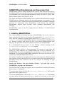
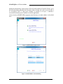
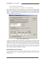
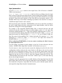
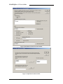
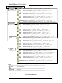
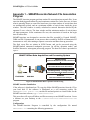
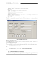
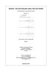
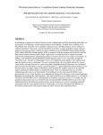
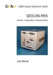
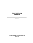
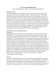
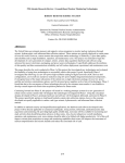
SMARTOffline v3.5 Offline Data Retrieval and Conversion Tool User’s Guide Copyright 2003-2011 Geotech Instruments, LLC Dallas, Texas SMARTOffline v3.5 User’s Guide DOCUMENT HISTORY Date ECN Rev Initials Description unkwn 1.0 MR Initial Release 05/16/03 2.0 MR Updated Document 07/01/03 2.1 MR Updated Document 01/24/04 2.2 MR Updated Document 08/20/04 3.0 MR Updated Document 09/20/04 3.1 MR Updated Document 10/06/04 3.2 MR Updated Document 01/12/05 3.3 MR Updated Document 08/18/05 3.4 MR Updated Document 09/20/06 3.5 MR Updated Document 4/5/11 3.5 MR Updated Document ii SMARTOffline v3.5 User’s Guide CONTENTS 1. INSTALLING SMARTOFFLINE........................................................................................................ 1 2. RUNNING SMARTOFFLINE.............................................................................................................. 3 INPUT DATA .............................................................................................................................................. 3 OUTPUT DATA........................................................................................................................................... 4 STARTING SMARTOFFLINE ...................................................................................................................... 5 SETTING CHANNEL DEFINITIONS (DL-24 ONLY) ........................................................................................ 6 DATA RETRIEVAL AND CONVERSION ........................................................................................................ 7 INPUT PARAMETERS................................................................................................................................... 8 OUTPUT PARAMETERS ............................................................................................................................. 10 3. REFERENCES ..................................................................................................................................... 12 APPENDIX 1 – SMARTASSOCIATE NETWORK FILE ASSOCIATION PROGRAM ............... 13 SMARTAssociate Installation............................................................................................................. 13 Configuration ..................................................................................................................................... 13 Running SMARTAssociate.................................................................................................................. 14 iii SMARTOffline v3.5 User’s Guide List of Figures Figure 1 SMARTOffline initial window ...................................................................................................... 2 Figure 2. SMARTOffline Activation Dialog................................................................................................ 2 Figure 3. SMARTOffline Activation Window............................................................................................. 3 Figure 4. Graphical User Interface of SMARTOffline................................................................................. 6 Figure 5. Channel Definitions window ........................................................................................................ 7 Figure 6. Data Retrieval and Conversion window ....................................................................................... 9 Figure 7. Input Data Locations window ....................................................................................................... 9 Figure 8. Output database folders (‘window’, ‘status’ used for DL-24 only, ‘log’ and ‘headers’ used for SMART-24R® only).......................................................................................................................... 11 Figure 9. SMART Offline Data Acquisition and Processing ..................................................................... 13 Figure 10. SMARTAssociate GUI ............................................................................................................. 14 iv SMARTOffline v3.5 User’s Guide SMARTOffline Data Retrieval and Conversion Tool SMARTOffline performs offline automated data retrieval from field disks recorded by the SMART-24R® series and DL-24 D-series recorders, and saving of the waveforms to a local database in one of the following data formats: SUDS, SAC, SEG Y, SEED, MiniSEED, SEISAN, MATLAB, CSS3.0 or ASCII. The station files output by SMARTOffline can be combined into network files using the SMARTAssociate automated network file association program (see Appendix 1). The resulted data set can be further processed using SMARTQuake® automated earthquake processor for local/distant event discrimination, event location and magnitude determination, moment tensor inversion, source parameters determination, data archiving. SMARTOffline works on any PC running Microsoft Windows 7/Vista/XP/2000/98 operating system. 1. Installing SMARTOffline First, choose a name for the home directory of SMARTOffline. Do not use a directory name containing the blank or dot character. Recommended is C:\smartoffline. Then, open the compressed SMARTOffline Install file e.g. ‘SMARTOffline v3.5 Install.zip’ from the SMARTOffline directory of the distribution CD-ROM using e.g. Windows Explorer, and extract all files to the chosen SMARTOffline home directory. This procedure will generate all files necessary to run SMARTOffline. It is recommended that you create on your Desktop a shortcut pointing to the C:\smartoffline\SMARTOffline.exe program. The SMARTOffline software is license protected. For versions 3.4 and earlier, the license key, either temporary for a SMARTOffline trial version or permanent for a SMARTOffline full version, is distributed from the factory as a file by email or on the distribution CD. After the SMARTOffline installation, the license key file has to be copied into the SMARTOffline home directory. For versions 3.5 and above, the application can run as trial version for a limited period of time (typically 30 days) after first time it is executed. It can be activated anytime into full permanent version, that is locked to the PC it is activated on, following the steps described below. Starting with Windows Vista, and including Windows 7, first time only, run the SMARTOffline program as an administrator. The first time when executing the program, and everytime before activation, the window shown in Figure 1 is displayed. To run the trial version click on the ‘Evaluate SMARTOffline’ link and the application will be started (see §2). To activate SMARTOffline, click on the ‘Activate SMARTOffline’ link and the activation dialog will open as shown in Figure 2. Submit to Geotech the two user codes 1 SMARTOffline v3.5 User’s Guide displayed in this dialog. Upon receipt of the activation number(s) from the factory, go to the activation dialog and enter the activation code(s) (if only one code is received enter it as ‘Activation Code 1’), then press Continue. A window as in Figure 3 confirms a successful activation; press Continue to start the application. After activation, SMARTOffline program starts directly to its main window as described next. Figure 1 SMARTOffline initial window Figure 2. SMARTOffline Activation Dialog 2 SMARTOffline v3.5 User’s Guide Figure 3. SMARTOffline Activation Window 2. Running SMARTOffline Input Data SMARTOffline input consists of data files of the SMART-24R® series and DL-24 Dseries instruments: raw data stored in the modified CD1.1 format for the SMART-24R® series instrument (Geotech Instruments, 2004) or in the HLCP internal format for the DL24 D-series instrument (Geotech Instruments, 2001), as well as header data files containing parametric information on the recorded data (SMART-24R® only) and log/status files containing log and status messages generated by the instrument, which are ASCII text files. To transfer and convert entire field data disks, prior to running SMARTOffline the disks should be either mounted as local drives on the working PC or copied, together with their original directory structure, to a local folder. SMARTOffline also handles any set of SMART-24R® raw data files retrieved from the unit and stored to a local folder on the PC (no specific directory structure required). To access and retrieve files stored in a SMART-24R® Series instrument, the user can use FTP to transfer files as needed via a TCP\IP connection. The user can also use the removable USB drive module to retrieve files directly by removing it from the unit and connecting it to PC USB port. To access and retrieve files stored in a DL-24 Series instrument, the user can use the removable PCMCIA drive to retrieve files directly by removing it from the unit and connecting it to the PCMCIA reader on the local PC. 3 SMARTOffline v3.5 User’s Guide Output Data SMARTOffline can output data in one of the following formats: SUDS, SAC, SEG Y, SEED, Mini-SEED, SEISAN, MATLAB, CSS3.0 and ASCII (multi-channel or singlechannel files). Raw data files are converted and the output data files are stored in the local database directories, depending on the data format selection and waveform recording type (continuous, event, window or calibration). When processing entire data disks, SMARTOffline also saves header files (SMART-24R® only) and log/status files to the output database. The SUDS data are in demultiplexed SUDS format version 1.51 (Banfill, 2002). This is a 32-bit version of the original PC-SUDS format (Ward, 1989; Banfill, 1999) that includes the full FDSN station and channel naming convention. Each output file contains all the data channels and has the following name: yyyymmdd_hhMMss_n_STACO.suds, where yyyy is the year, mm the month, dd the day of month, hh the hour, MM the minute, ss the second corresponding to the time stamp of the first sample in the data stream; n is ’1’ for primary rate channels and ’2’ for secondary rate channels in case of DL-24 data and ‘C’, ‘E’ or ‘B’ for continuous, event or calibration SMART-24R® data, respectively; STACO is the station code of 5 characters and ‘suds’ is the file extension, common for all files. The SAC data are in binary SAC format (Tapley and Tull, 1991). There is one file per data channel. The filename is the same as for the SUDS data file and has the extension ‘sac_nnn’, where nnn is a 3-digit channel index between 000-999. The SEG Y data are in PASSCAL SEG Y trace format, a modified form of the standard SEG Y format originally established by the Society of Exploration Geophysicists. Each file contains one trace and has the name: yyyymmdd_hhMMss_n_NET_STACO_CMP.segy, where yyyy is the year, mm the month, dd the day of month, hh the hour, MM the minute, ss the second corresponding to the time stamp of the first sample in the data stream; n is ’1’ for primary rate channels and ’2’ for secondary rate channels in case of DL-24 data and ‘C’, ‘E’ or ‘B’ for continuous, event or calibration SMART-24R® data, respectively; NET is the network code (up to 3 characters), STACO the station code (up to 5 characters), CMP the component code (up to 3 characters) and ‘segy’ the file extension, common for all files. The SEED data are SEED Volumes (IRIS, 1993). Each file contains all the data channels and has the same name as the SUDS data file, but the extension ‘seed’. The Mini-SEED data are Data Only SEED Volumes (IRIS, 1993). Each file contains all the data channels and has the same name as the SUDS data file, but the extension ‘msed’. The SEISAN data are SEISAN version 7.x files (Havskov and Ottemöller, 2001). Each file contains all the data channels and has the name following the SEISAN naming convention: yyyy-mm-dd-hhMM-ssS_n.STACO_nnn, where yyyy is the year, mm the month, dd the day of month, hh the hour, MM the minute, ss the second corresponding to the time stamp of the first sample in the data stream; n is ’1’ for primary rate channels and ’2’ for secondary rate channels in case of DL-24 data and ‘C’, ‘E’ or ‘B’ for continuous, event or calibration SMART-24R® data, respectively; STACO 4 SMARTOffline v3.5 User’s Guide is the station code (up to 5 characters), and nnn is the (3-digit) number of channels in the file. The MATLAB data are in binary MATLAB Version 4 format compatible with the MATLAB software by MathWorks (Version 4 or higher). Each file contains all the data channels and has the same name as the SUDS data file, but the extension ‘mat’. The CSS3.0 data are written to a CSS3.0 database (see Science Applications International Corporation, 2001) in the .w subfolder. The CSS .wfdisc, .sitechan and .lastid tables are output in the local database directory of the corresponding waveform recording type (continuous, event, window or calibration). The ASCII multi-channel files (for SMART-24R® only) are written in a simple ASCII (text) format. Each file contains all the data channels and has the same name as the SUDS data file, but the extension ‘asc’. For each data channel, a 4-line header gives on first line the network, station and component identifiers as NET:STACO:CMP, where NET is the network code (up to 8 characters), STACO the station code (up to 5 characters) and CMP the component code (up to 3 characters); on the second line the initial sample time as mm/dd/yy hhMMss.xxx, where mm is the month, dd the day of month, yy the last two digits of the year, hh the hour, MM the minute, ss the second and xxx the millisecond corresponding to the time stamp of the first sample in the data stream; on the third line the sample rate (real number); on the fourth line the number of samples recorded for the given channel, followed by data values as one sample (integer number) per line. All data channels follow sequentially in one file. The ASCII single-channel files (for SMART-24R® only) are written in a simple ASCII (text) format. They are named yyyymmdd_hhMMss_n_STACO_CMP.asc, where yyyy is the year, mm the month, dd the day of month, hh the hour, MM the minute, ss the second corresponding to the time stamp of the first sample in the data stream; n is ‘C’, ‘E’ or ‘B’ for continuous, event or calibration data, respectively; STACO is the station code (up to 5 characters), CMP the component code (up to 3 characters) and ‘asc’ is the file extension. Each data file has one header line starting with ‘H’ followed by the initial sample time as epoch time (number of seconds since 01/01/1970, 00:00:00), the sample rate, channel number and bit weight in Volts/count. The header line is followed by the data values in counts for that channel only. Starting SMARTOffline To start SMARTOffline, double click on the SMARTOffline icon on the Desktop. The graphical user interface shown in Figure 4 will be displayed. The first menu, Commands, allows issuing the main commands for data handling and provides access to the operational message log. The second menu, Settings, allows setting-up the DL-24 channel definitions for the output data files. The SMARTOffline Messages window provides a summary operation report, listing the performed actions and the number of the data files output to the database. 5 SMARTOffline v3.5 User’s Guide A detailed history of the operation messages including the names of the data files output to the database is available from the Commands/View Message History menu. The messages history, stored in the file C:\smartoffline\smartoffline.log, can be cleared by selecting the Commands/Clear Message History menu. Otherwise, once the current log file size exceeds 1 Megabyte or becomes older than 1 month, SMARTOffline renames it as C:\smartoffline\smartoffline_YYYY-MM-DD.log, where YYYY, MM and DD are the year, month and day of the oldest log message in the file. The SMARTOffline distribution includes examples of configuration parameters that the user should edit according to the actual system settings. Figure 4. Graphical User Interface of SMARTOffline Setting channel definitions (DL-24 only) This option available from the Settings menu allows the user to set-up the channel information for the output data files. In the HLCP format of the DL-24 raw data files, each input data channel is uniquely defined by the station name (up to 4 characters) and the channel identifier present in the input file name (a single character ‘1’ to ‘6’ for channels 1-6 primary sample rate or to ‘A’ to ‘F’ for channels 1-6 secondary sample rate). For every channel, four fields can be defined by the user to be written in the output files: - A new station name (up to five characters) to replace, optionally, the current station name. To keep the existing station name, leave this field blank. - Component name (up to three characters). 6 SMARTOffline v3.5 User’s Guide - Network name (up to three characters). - Sensor type, one character, ‘v’ for velocity or ‘a’ for acceleration. For any input channel where these descriptors are not defined, the following defaults apply for the output files: the input station name is preserved, the original channel identifier is used as component name, the network name is set to ‘unk’ and the sensor type to ‘_’ (undefined). The list of channel definitions can be changed from within the configuration window shown in Figure 5. Figure 5. Channel Definitions window To add a new channel and enter its properties, use the edit line on the bottom of the configuration window, then press Update. To change the definitions for a given channel, use the mouse to select it from the list, and then press Edit to move that channel in the edit line, where changes can be made. Pressing Update will bring the selected channel back in the list. To remove a channel from the list, select it with the mouse and press Delete. Once the channel information is set-up, click on OK to save the settings or on Exit to cancel the changes and keep the old settings. Data Retrieval and Conversion To start retrieving data select the ‘Get Data’ command from the Commands menu. The window shown in Figure 6 is opened, displaying the parameters to be set-up before running the task. 7 SMARTOffline v3.5 User’s Guide Input parameters Use the Recorder Type switch to select input from a DL-24 D-series or SMART24R® series instrument. List of input data locations is the list of drives or folders where the input data are stored. Each represents either the drive letter assigned by the Windows operating system for the field disk connected directly to the PC port (USB or PCMCIA), or a folder on the PC where the entire structure of the field disk was previously copied, or (for SMART-24R® only) a local folder containing any number of raw data files. As many as 100 different input locations can be entered. When processing entire data disks, SMARTOffline converts raw data files according to the user’s output format selection, saving them to the output database, and also copies header files and log files to the output database. For example, if the removable SMART-24R® disk is removed from the unit and connected to the PC USB port being accessible locally as drive ‘E’, the input data location for SMARTOffline is ‘E:’. If the entire SMART-24R® data disk (e.g. drive ‘D’) was retrieved from the unit by FTP and saved into the local PC folder ‘c:\data’, the input data location for SMARTOffline is ‘c:\data\D’. If a set of SMART-24R® raw data files (stored in the modified CD1.1 format, having the file extension ’cd11’) was transferred to a local PC folder ‘c:\localdata’, the input data location for SMARTOffline is ‘c:\localdata’. When configuring SMARTOffline, do not use names containing the blank character for input/output directories. Use the Change List button to make changes to the list. For this selection, the next window, ‘SMARTOffline Input Data Locations’ will be shown (see Figure 7). Use the mouse to select items from the current list (displayed on the left side of the configuration window) and press the arrow button to add them to the new list (on the right side of the configuration window). Also, you can type the location name in the edit line and press the Add button to add the item to the new list. When ready, press the OK button to save the new list or Exit to cancel the changes keeping the old list. The ‘SMARTOffline Data Retrieval and Conversion’ window (Figure 6) will return showing the new list of input locations. If desired, check the appropriate box to enable deleting of the input data from the field disks folders and/or drives after saving the output data to the local database. Leaving the box unchecked will preserve input data files, but they can be deleted anytime later by selecting Delete Input Data from the Commands menu. 8 SMARTOffline v3.5 User’s Guide Figure 6. Data Retrieval and Conversion window Figure 7. Input Data Locations window 9 SMARTOffline v3.5 User’s Guide Output parameters Enter the ‘Home folder of the local database’ where output files will be stored. SMARTOffline uses (as necessary) the database directory structure shown in Figure 8, depending on the recorder type and on the active selection of the output formats. All necessary directories are generated by SMARTOffline at run-time. Window and Status folders are used for DL-24 only, while Log and Headers folders are used for SMART-24R® only. For SMART-24R® using window recording, data are output to the Cont or Event folder depending whether the recording window was set to record in continuous or event mode. If desired, check the appropriate box ‘Overwrite existing files’ to enable overwriting of the output data in the local database if destination files already exist. Leaving the box unchecked will skip transfer and conversion for already existing files. Check the appropriate boxes to enable the desired output in any combination of the following formats: SUDS, SAC, SEG Y, SEED, Mini-SEED, SEISAN, MATLAB, CSS3.0 and ASCII. Optionally, the output SEED volumes can include the appropriate instrument response information. To enable this feature, enter the ‘Calibration folder’ that contains the response files in SEISAN format as poles and zeros (see Havskov and Ottemöller, 2001, Appendix 3, option 3). Two types of ASCII format conversion are available for SMART-24R® data only, as multi-channel or single-channel files. Check the appropriate box to enable output of single-channel files, or leave the box unchecked to output multi-channel files. Optionally, if the box to ‘Keep a copy of the raw data’ is checked, the raw data are mirrored on the local computer in the folder entered as ‘Home folder for mirrored raw data’. Each field disk with its entire directory structure is copied to a subdirectory of the home folder named sta_yyyy-mm-dd-hh-MM-ss, where sta is the last 3-digits of the DL-24 instrument serial number or the 5-character station name for an SMART-24R® instrument, yyyy is the year, mm the month, dd the day of month, hh the hour, MM the minute and ss the second of the time when the SMARTOffline processing is done. Once all the parameters are set-up, click OK to proceed or Exit to cancel the execution. Configuration changes in the ‘SMARTOffline Data Retrieval and Conversion’ window (Figure 6) are saved only when pressing the OK button. The input data files are then read from the field disks, converted to the selected formats and saved to the database. The SMARTOffline Messages window shows a summary on the performed operations, while detailed logging information is available from the Commands/View Message History menu. After the completion of the task, the user can choose to set-up and run a new task or to close the program by selecting Exit from the Commands menu. 10 SMARTOffline v3.5 User’s Guide DATABASE HOME FOLDER cont event window cal suds sac segy msed seed sei mat ascii headers .w suds sac segy msed seed sei mat ascii headers .w suds sac segy msed seed sei mat .w suds sac segy msed seed sei mat ascii headers .w SUDS continuous files: yyyymmdd_hhMMss_n_STACO.suds SAC continuous files: yyyymmdd_hhMMss_n_STACO.sac_nnn SEGY continuous files: yyyymmdd_hhMMss_n_NET_STACO_CMP.segy Mini-SEED continuous files: yyyymmdd_hhMMss_n_STACO.msed SEED continuous files: yyyymmdd_hhMMss_n_STACO.seed SEISAN continuous files: yyyy-mm-dd-hhMM-ssS_n.STACO_nnn MATLAB continuous files: yyyymmdd_hhMMss_n_STACO.mat ASCII continuous files: yyyymmdd_hhMMss_n_STACO(_CMP).asc Headers for continuous files: yyyymmdd_hhMMss_n_STACO.txt CSS3.0 continuous waveform files: STACOyyyy doy hhMM STACO CMP.w SUDS event files: yyyymmdd_hhMMss_n_STACO.suds SAC event files: yyyymmdd_hhMMss_n_STACO.sac_nnn SEGY event files: yyyymmdd_hhMMss_n_NET_STACO_CMP.segy Mini-SEED event files: yyyymmdd_hhMMss_n_STACO.msed SEED event files: yyyymmdd_hhMMss_n_STACO.seed SEISAN event files: yyyy-mm-dd-hhMM-ssS_n.STACO_nnn MATLAB event files: yyyymmdd_hhMMss_n_STACO.mat ASCII event files: yyyymmdd_hhMMss_n_STACO(_CMP).asc Headers for event files: yyyymmdd_hhMMss_n_STACO.txt CSS3.0 event waveform files: STACOyyyy doy hhMM STACO CMP.w SUDS window files: yyyymmdd_hhMMss_n_STACO.suds SAC window files: yyyymmdd_hhMMss_n_STACO.sac_nnn SEGY window files: yyyymmdd_hhMMss_n_NET_STACO_CMP.segy Mini-SEED window files: yyyymmdd_hhMMss_n_STACO.msed SEED window files: yyyymmdd_hhMMss_n_STACO.seed SEISAN window files: yyyy-mm-dd-hhMM-ssS_n.STACO_nnn MATLAB window files: yyyymmdd_hhMMss_n_STACO.mat CSS3.0 window waveform files: STACOyyyy doy hhMM STACO CMP.w SUDS calibration files: yyyymmdd_hhMMss_n_STACO.suds SAC calibration files: yyyymmdd_hhMMss_n_STACO.sac_nnn SEGY calibration files: yyyymmdd_hhMMss_n_NET_STACO_CMP.segy Mini-SEED calibration files: yyyymmdd_hhMMss_n_STACO.msed SEED calibration files: yyyymmdd_hhMMss_n_STACO.seed SEISAN calibration files: yyyy-mm-dd-hhMM-ssS_n.STACO_nnn MATLAB calibration files: yyyymmdd_hhMMss_n_STACO.mat ASCII calibration files: yyyymmdd_hhMMss_n_STACO(_CMP).asc Headers for calibration files: yyyymmdd_hhMMss_n_STACO.txt CSS3.0 calibration waveform files: STACOyyyy_doy_hhMM_STACO_CMP.w log Log calibration files: yyyymmdd_hhMMss_L_STACO.log soh State-of health files status Status files Figure 8. Output database folders (‘window’, ‘status’ used for DL-24 only, ‘log’ and ‘headers’ used for SMART-24R® only) 11 SMARTOffline v3.5 User’s Guide 3. References Banfill, R., 1999. PC-SUDS Utilities Version 2.60, Banfill Software Engineering, Big Water, Utah, 180p. Banfill, R., 2002. Win-SUDS Utilities Version 2.86, Banfill Software Engineering, Valdez, Alaska, 7p. Geotech Instruments, LLC, 2001. D-Series HLCP Protocol Interface Control Document, Version 2.3, Dallas, Texas, 123 p. Geotech Instruments, LLC, 2004. SMART Series Command & Setup Protocol Interface Control Document, Version 1.6, Dallas, Texas, 100 p. Havskov, J. and Ottemöller, L., 2001. SEISAN: The Earthquake Analysis Software, Version 7.2, University of Bergen, Norway, 256 p. Incorporated Research Institutions for Seismology (IRIS), 1993. Standard for the Exchange of Earthquake Data (SEED), Reference Manual, 205 p. Science Applications International Corporation, 2001. IDC5.1.1Rev3 - IDC Documentation Database Schema, Revision 3, SAIC-01/3052, Veridian Systems. Tapley, W.C. and Tull, J.E., 1991. SAC - Seismic Analysis Code: User’s manual, Rev.3, Lawrence Livermore National Laboratory, Livermore, California. Ward, P., 1989. SUDS - Seismic Unified Data System. USGS Open-File Report 89-188, Denver, Colorado. 12 SMARTOffline v3.5 User’s Guide Appendix 1 – SMARTAssociate Network File Association Program The SMARTAssociate program performs station file association into network files. It can associate both triggered station files and continuous station files. In the first case, it forms what is generally known as event files based on a given time window of arrival times that are automatically picked, and on a minimum number of arrival times inside the given window. The time window is usually calculated as network dimension divided by the apparent P wave velocity. The time window and the minimum number of arrival times are input parameters. In the continuous file case, the association is based on the begin time of station files. SMARTAssociate was designed to associate data files recorded by Geotech SMART24R® and DL-24 instruments. It can process data recorded by RefTek or Kinemetrics K2 instruments as well, after running a separate conversion and data clean up procedure. The final event files are written in SUDS format, and can be processed using the SMARTQuake® automated earthquake processor (in off-line operation mode), and SeisPlus interactive seismogram processing program. The data flow chart is presented in Figure 9. SMART Offline Data Acquisition and Processing System SMARTOffline Automated Data Retrieval and Conversions SMARTAssociate Automated Network File Association SMARTQuake® running offline Automated Earthquake Data Processing Field Disks USB Hub SeisPlus Interactive Seismic Data Analysis Figure 9. SMART Offline Data Acquisition and Processing SMARTAssociate Installation If the software is distributed on CD, copy the folder SMARTAssociate from the CD to your hard disk. If the software is distributed as a self extracting archive file SMARTAssociate Install.exe, run this file and and point it to a home folder for the SMARTAssociate software, e.g. C:\smartassociate. This procedure will create all folders and files necessary to run SMARTAssociate. Create a shortcut on your Desktop to the C:\smartassociate\smartassociate.exe program. Configuration The SMARTAssociate Program is controlled by the configuration file named smartassoc.ini containing the following parameters: 13 SMARTOffline v3.5 User’s Guide ;Time interval (sec) to associate P-arrivals: Time_window=30 ;Minimum number of stations to associate events: Nmin_sta=3 ;Names of components for picking P-arrivals: P_Comp=V ;Input data folder: Input_folder=c:\mike\dataset\indata ;Output data folder: Output_folder=c:\outdata1 ;Flag to autopick P-arrivals (if set to 0 file begin time will be used instead of P-arrivals): Auto_pick=1 This file is automatically generated from the GUI (as in Figure 10), so the user doesn't need to edit it. Figure 10. SMARTAssociate GUI Running SMARTAssociate The input SUDS files (with any names) recorded at different stations should all be present in the input data folder. The event SUDS files will be stored in the output data folder, with the following names: YYYYMMDD_hhmmss_net.suds or YYYYMMDD_hhmmss_staco.suds (files with one station only) Where NET is the network name (up to 8 characters) STACO is the long station name assigned to the recording station (up to 5 characters) 14 SMARTOffline v3.5 User’s Guide YYYY=4-digit year, MM=month, DD=day of month, hh=hour, mm=minute, ss=second of the first data sample in the file, and 'suds'=the filename extension. Make sure to use unique station names when running the procedure to associate different recording stations! By double clicking on the SMARTAssociate icon on the desktop, the program will perform the following tasks: - Filtering of all input station files, followed by automatic picking on the components defined in the list of components for picking P-arrivals set in the configuration file. - If no picks are found on the requested components, the station file is renamed according to the output filename convention (YYYYMMDD_hhmmss_staco.suds) and stored in the subfolder UNASSOC of the output folder. - For every station one pick is selected and stored for association purposes, corresponding to the first component from list found in the input file. The list of station picks is output to the file smartassoc.pha in the SMARTAssociate home directory. - Station files with picks that fall inside a time window of length less than or equal to the Time interval (sec) to associate P-arrivals parameter (dependent on the network dimension and apparent wave velocity) are merged together in the same event file. The names of the merged station files are listed in the log file smartassoc.log in the SMARTAssociate home directory. - If duplicate picks from the same station (belonging to separate files) are found within the event time window, only the station file corresponding to the earliest pick is considered for merging and formation of the event file. The station file corresponding to the later pick is renamed according to the output filename convention (YYYYMMDD_hhmmss_staco.suds) and stored in the subfolder UNASSOC of the output folder. Duplicate picks are logged in the file smartassoc.log. - Output files are checked and corrected for unique short station name identifiers in the SUDS structures. - Output files with a number of picks greater than or equal to the Minimum number of stations to associate events parameter are renamed according to the output filename convention (YYYYMMDD_hhmmss_net.suds) and stored in the output folder. - Output files with a number of picks less than the Minimum number of stations to associate events parameter are renamed according to the output filename convention (YYYYMMDD_hhmmss_net.suds for event files with at least two stations, or YYYYMMDD_hhmmss_staco.suds for files with one station only), and stored in the subfolder "UNASSOC" of the output folder. - If the Autopick option is turned off (by setting the auto_pick flag to 0 in file smartassoc.ini) the file begin times on the requested components are used for 15 SMARTOffline v3.5 User’s Guide file association instead of the P-arrival times. This option is used in the case of continuous file recording. 16