1
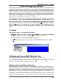
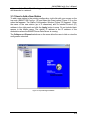
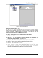
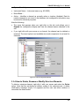
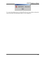
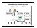
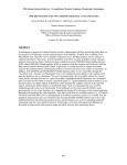
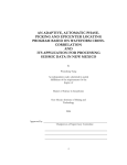
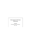
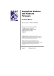
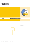
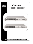
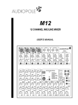
SMARTDBConfig
User’s Manual
Version 1.4
Copyright © 2003-2006 Geotech Instruments, LLC
Dallas, Texas
Revision History
Rev
Date
Description
By
1.0
8/15/03 Preliminary Release
1.1
6/14/04 First Release
PCK
1.2
8/04/04 Screenshots and some text updated
CRP
1.3
7/28/05 Some text updated
MR
1.4
2/1/06
MR
Updates
SMARTDBConfig User’s Manual
Table of Contents
ABOUT THIS DOCUMENT..............................................................................................................................V
1 GENERAL INFORMATION....................................................................................................................... 1-1
1.1 SMARTDBCONFIG CLIENT OVERVIEW .................................................................................................... 1-1
1.2 SYSTEM REQUIREMENTS ............................................................................................................................ 1-1
2 SMARTDBCONFIG CLIENT INSTALLATION ..................................................................................... 2-1
3 SMARTDBCONFIG CLIENT OPERATION............................................................................................ 3-1
3.1 TOOLBAR ................................................................................................................................................... 3-1
3.2 STARTING AND CLOSING SMARTDBCONFIG CLIENT ............................................................................... 3-1
3.3 HOW TO CREATE A DATABASE STRUCTURE ............................................................................................... 3-1
3.3.1 How to Add a New Station .................................................................................................................. 3-2
3.3.2 How to Add a New Site........................................................................................................................ 3-3
3.3.3 How to Add a New Channel ................................................................................................................ 3-4
3.3.4 How to Delete, Rename or Modify Structure Elements....................................................................... 3-5
3.3.5 Error Messages ................................................................................................................................... 3-6
4 APPENDIX A. SMARTGEOHUB® CENTRAL STATION DATA FLOW DIAGRAM ...................... 4-1
i
SMARTDBConfig User’s Manual
( Page Intentionally Left Blank )
ii
SMARTDBConfig User’s Manual
List of Figures
Figure 1-1. SMARTDBConfig Client................................................................ 1-1
Figure 3-1. Toolbar ......................................................................................... 3-1
Figure 3-2. Top Node Right Click Menu.......................................................... 3-2
Figure 3-3. Station Configuration Window ...................................................... 3-3
Figure 3-4. Site Configuration Window ........................................................... 3-4
Figure 3-5. Channel Configuration Window .................................................... 3-5
Figure 3-6. Typical Delete Confirmation Message .......................................... 3-6
iii
SMARTDBConfig User’s Manual
( Page Intentionally Left Blank )
iv
SMARTDBConfig User’s Manual
About This Document
This manual is designed for technical personnel installing and operating Geotech
Instruments’ SMARTDBConfig Client application. The following chapters are
included in this manual:
•
Chapter 1, General Information about SMARTDBConfig Client
•
Chapter 2, Installation and Setup
•
Chapter 3, SMARTDBConfig Client Features and Operation
v
SMARTDBConfig User’s Manual
( Page Intentionally Left Blank )
vi
SMARTDBConfig User’s Manual
1 General Information
1.1 SMARTDBConfig Client Overview
SMARTGeoHub® is a multi-threaded, data acquisition system for real time
operation. Data sources are SMART-24 Series instruments, DR-24 D-Series
Remote Digitizers, or other digitizers communicating through supported protocols
(SeedLink, Earthworm). A data server (SMARTServer) stores seismic array data on
a backend relational database, as shown in the figure in Appendix A.
SMARTGeoHub® can also send data to other data acquisition systems using the
SeedLink, Earthworm or CD1.1 protocol.
SMARTDBConfig Client (Figure 1-1) creates the structure used by this database.
The database structure consists of stations, sites, and channels. Channels are
defined as the sensor outputs for a specific site. A station may include several sites.
Remote sites connect to the SMARTGeoHub® over a TCP/IP network. They
communicate through a well-defined protocol that authenticates pre-defined clients.
In order for the SMARTGeoHub® to accept remote connections from remote sites,
the seismic array network must be configured in the database.
Figure 1-1. SMARTDBConfig Client
1.2 System Requirements
The minimal hardware requirements are: a computer with Intel Pentium IV™ @
2.26GHz processor, 512 MB RAM, with Microsoft Windows XP™ operating system.
Additional resources may be required to support large seismic networks. Support for
Linux and Unix operating systems is also available. The computer must support
1-1
SMARTDBConfig User’s Manual
Sun’s Java Virtual Machine and include a relational database (such as Oracle,
MySQL, Postgress, SyBase, Cloudscape, etc.) that has a Java Data Base
Connectivity (JDBC) driver.
1-2
SMARTDBConfig User’s Manual
2 SMARTDBConfig Client Installation
The SMARTDBConfig Client is installed as part of the SMARTGeoHub® data
acquisition system. The install procedure is very simple and automated, as
described below.
To install SMARTGeoHub® onto your computer:
Insert the Geotech’s SMARTGeoHub® CD in the system CD drive and double-click
on the Install program from the CD root directory. This procedure will create all
folders and will copy all files necessary to run SMARTGeoHub®. On a Windows
platform the installation folder defaults to c:\SmartGeoHub, where the
SMARTGeoHub® programs will be installed in different subfolders, one for each
software component.
Next, the Java Runtime Environment will be installed, or updated to the newest
version if already present on the computer. The Typical setup should be selected
during the Java Runtime Environment Install Wizard.
The install procedure will also install the relational database needed by
SMARTGeoHub®.
This installation procedure assumes that you have no current SMARTGeoHub®
installation on the computer. Another procedure should be used to update or reinstall SMARTGeoHub®, by double-clicking on the Update program from the CD
root directory. The update procedure is similar to the install procedure but it excludes
the installation of the relational database.
When the software installation is completed, it is recommended to create (or update
existing) shortcuts on the Desktop to point to the SMARTGeoHub® programs. The
SMARTDBConfig shortcut should point to the following program file (given here as
an example):
c:\SMARTGeoHub\SMARTDB_Config\bin\SmartDB_Config.bat.
Also, it is recommended to set the program icon (by editing the shortcut Properties)
to point to: c:\SMARTGeoHub\icons\SmartDBConfig.ico
Double-click on the SMARTDBConfig icon to start the SMARTDBConfig Client.
2-1
SMARTDBConfig User’s Manual
( Page Intentionally Left Blank )
2-2
SMARTDBConfig User’s Manual
3 SMARTDBConfig Client Operation
This chapter describes how to use the SMARTDBConfig Client. The Client desktop
consists of three areas, a small tool bar, an area for creation and display of the
database structure, and an area for structure settings. Users should be prepared to
create a structure for their station(s), sites, and channels; and identify specific
information for each element of the structure. This includes information such as the
sensor type and sensitivity; site location (latitude, longitude, and elevation) and IP
(Internet Protocol) address; and network IP address.
The bar between the structure area and settings is movable to facilitate viewing of
the information. If the structure exceeds the available area, scrollbars appear at the
bottom and right edges. The structure is expandable and collapsable by clicking the
symbol to the left of any structure element. When Select All Channels is clicked
under Configure in the toolbar, all structure elements are expanded and all
channels are selected. This facilitates channel settings when all channels are
similar.
3.1 Toolbar
The toolbar (Figure 3-1) includes three functions:
•
Configure allows the user to Select All Channels in a network, facilitating
information entry when all of the settings are the same or similar.
•
The Exit selection closes the SMARTDBConfig client.
•
The Help tab will provide information about the SMARTDBConfig Client (TBD).
Figure 3-1. Toolbar
3.2 Starting and Closing SMARTDBConfig Client
Start SMARTDBConfig Client by double clicking on its shortcut icon.
To close SMARTDBConfig Client, either click Configure followed by Exit or click the
X button in the application’s upper right corner.
3.3 How to Create a Database Structure
SMART database structure consists of a network of station(s) monitoring one or
more sites and the sensor channels that send data to sites. In typical seismological
applications, a ‘station’ is defined as a seismic network consisting of seismic stations
(here referred to as ‘sites’) with sensors having components (here referred to as
‘channels’). The configuration window, the left area below the toolbar, is where you’ll
create the network structure. You’ll enter the details for each structure element in the
3-1
SMARTDBConfig User’s Manual
right area of the Client. The following procedures tell you how to add stations, sites,
and channels to a network.
3.3.1 How to Add a New Station
To add a new station to the existing configuration, right click with your mouse on the
top node (SMART DB Config v.1.0) and select the Insert option (Figure 3-3) on the
menu that appears. The Station Configuration Window (Figure 3-3) appears. Enter
the name of the new station (up to 8 characters) and its Internet Protocol (IP)
address in the right panel and click the Apply button to save. Do not include blank
spaces in the station name. The station IP address is the IP address of the
workstation where the SMARTServer Data Server is running.
The Collapse and Expand selections on the menu allow the user to hide or view the
configuration structure.
Figure 3-2. Top Node Right Click Menu
3-2
SMARTDBConfig User’s Manual
Figure 3-3. Station Configuration Window
3.3.2 How to Add a New Site
To add a site to a station, right click with your mouse on on the parent network
station node and select the Insert option (Figure 3-3).The Site Configuration Window
(Figure 3-4) appears. Enter the name of the new site in the right panel and the
following information and click the Apply button to save:
•
Name – The site name (up to 5 characters without blank spaces).
•
IP: – The site IP address
•
Data Port: - The port number at which the digitizer and SmartServer will
communicate (usually between 10000 and 32767)
•
Longitude – The site location longitude in degrees (north being positive)
•
Latitude – The site location latitude in degrees (east being positive)
•
Elevation – The site elevation in meters
•
Active – Identifies a site as enabled (active) or disabled (inactive). Only active
sites are allowed to connect to the SMARTGeoHub® server. Configuration
information for inactive sites may be stored for historical purposes.
3-3
SMARTDBConfig User’s Manual
Figure 3-4. Site Configuration Window
3.3.3 How to Add a New Channel
To add a channel to a site, right click with your mouse on on the parent site node
and select the Insert option (Figure 3-4). The Channel Configuration Window (Figure
3-5) appears. Enter the name of the new channel in the right panel, the following
information, and click the Apply button to save:
•
Name – The channel name (up to three characters without blank spaces).
•
Location Name – An optional two character field used to differentiate between
two like channels at the same site. For example, two vertical component
channels could exist at the same site.
•
Channel Type –
•
Sensor Type – Single character designation of sensor type. Choose from
acceleration sensor (a), hydroacoustic sensor (h), infrasound sensor (i), velocity
sensor (v) or weather sensor (w). ‘S’ can also be used to designate other types of
seismic sensors.
•
Sensor Sensitivity – The sensor sensitivity given in Volts/(m/s) or Volts/(m/s2) for
velocity and acceleration sensors, respectively
•
Natural Period – Sensor natural period in seconds.
•
Damping – Sensor damping in fractions of critical damping
•
Calibration Period – The sensor calibration period in seconds.
•
Bit Weight – Digitizer bit weight, in μVolts/digital counts.
3-4
SMARTDBConfig User’s Manual
•
System Sensitivity –
•
Instrument Name – Instrument name (e.g. KS-2000)
•
Broad Band –
•
Active – Identifies a channel as currently active or inactive (disabled). Data for
inactive channels is not stored in the database, but configuration information may
be stored for historical purposes.
Note the following:
•
The menu that appears when you right click on the site node allows you to
Expand the configuration display and view the channel names attached to the
site.
•
If you right click with your mouse on a channel, the channel can be deleted or
renamed. The insert option is not available since sub-components do not exist for
channels.
Figure 3-5. Channel Configuration Window
3.3.4 How to Delete, Rename or Modify Structure Elements
To delete a structure element, right click it with your mouse and select the Delete
option. Note that this will delete all children nodes of the selected node. A delete
confirmation message (Figure 3-6) appears and the user can either continue or
reconsider the delete action.
3-5
SMARTDBConfig User’s Manual
Figure 3-6. Typical Delete Confirmation Message
To rename a structure element, right click it with your mouse select the Rename
option. Type the new name either in the structure window or in the right panel. If you
type it in the right panel, it appears in the structure when you click Apply.
To modify a structure element, simply left click it with your mouse and change the
information in the right panel. Click the Apply button at the bottom of the right panel
when changes are complete. Clicking the Discard button deletes the user’s entries.
3.3.5 Error Messages
The application tells you if any of the names are too long or the IP address is invalid
(if you forgot to enter the address, its in the wrong form or there are too few or too
many numbers). For example:
3-6
SMARTDBConfig User’s Manual
You must acknowledge errors by clicking OK with your mouse before entering the
correct information and attempting to apply it to the configuration.
3-7
SMARTDBConfig User’s Manual
4 Appendix A. SMARTGeoHub® Central Station Data Flow Diagram
SMARTGeoHub® Central Station
DR-24
SMART-24D®
HLCP
DR2SMART
Remote Setup & Data
SMARTGeoViewer®
Display Client
SMART24Config
Remote Setup Client
CD1.1
SMARTDBConfig
Data Base Setup Client
CD1.1
SMARTServer
Data Server and Forwarder
SMARTGeoSOH
Monitor Client
Data Base
SMARTSUDSGen
Data Client
SeedLinkToSMART
Data Server
CD1.1
SMARTGeoHub® Central Station
NDC/IDC
EarthWorm
SeisComp
USGS LISS
SMARTQuake®
SMARTShake
Typical Configuration
4-1
SMARTDBConfig User’s Manual
( Page Intentionally Left Blank )
4-2