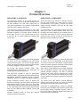
1
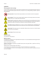
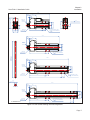
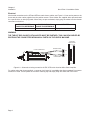
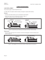
ServoTube 11
INSTALLATION GUIDE
Publication Ref: UM03015/A
Copley Motion Systems LLC
Luckyn Lane, Pipps Hill, Basildon, Essex SS14 3BW England
Tel: +44 (0)1268 287070
Fax +44 (0)1268 293344
Prelims
ServoTube 11 Installation Guide
WARRANTY
Copley Motion Systems guarantees its equipment against faulty components for a period of twelve months from
delivery. Replacement components will be free of charge. Copley Motion Systems shall not in any event be liable
for consequential damage or loss.
Copley Motion Systems operates a customer care facility and all requests for repair and replacement should
be directed to the Customer Care Department. The serial number of the equipment should be quoted in any
communications. The right to change specification and price is reserved by Copley Motion Systems.
DISCLAIMER
Copley Motion Systems makes no guarantees of any kind with regard to this manual. Copley Motion Systems
shall not be liable for errors contained herein or for consequential or incidental damages incurred as a result of
acting on information contained in the manual.
CUSTOMER CARE
For enquiries relating to the operation and use of the ServoTube 11 described in this Manual please contact the
Customer Care Helpdesk, Telephone : +44 (0)1268 287070.
Copley Motion Systems LLC
Luckyn Lane, Pipps Hill, Basildon, Essex SS14 3BW England
Tel: +44 (0)1268 287070 Fax: +44 (0)1268 293344
(c) Copley Motion Systems 2007
INTERNATIONAL CONTACT DETAILS
website: http//www.copleycontrols.com
Page (ii)
World Headquarters, USA
Copley Controls Corp.
20 Dan Road,
Canton,
MA 02021
USA
European Headquarters
Copley Motion Systems LLC
Luckyn Lane,
Pipps Hill,
Basildon, Essex SS14 3BW
England
Tel: +1 781 828 8090
Fax: +1 781 828 1750
Tel: +44 (0)1268 287070
Fax: +44 (0)1268 293344
ServoTube 11 Installation Guide
Prelims
ServoTube 11
INSTALLATION GUIDE
Contents
Preliminary pages
Title page .................................................................................................................... (i)
Copyright notice / disclaimer...................................................................................... (ii)
Contents list (this page) ............................................................................................ (iii)
Warnings .................................................................................................................. (iv)
Cautions..................................................................................................................... (v)
Reader’s Notes ......................................................................................................... (vi)
Abbreviations ........................................................................................................... (vii)
Chapters
1 Overview ................................................................................................................ 1
2 Installation.............................................................................................................. 3
3 Maintenance .......................................................................................................... 9
4 Service ................................................................................................................. 13
Appendices
A Glossary of terms & Abbreviations....................................................................... 17
B Trouble Shooting.................................................................................................. 19
C Technical Specification ........................................................................................ 20
Page (iii)
Prelims
ServoTube 11 Installation Guide
WARNINGS
Warning symbols and meanings
In this User Manual warning symbols are used. These are intended to alert you to the potential hazards to personnel
which are associated with the equipment described, in all aspects of use, including handling, installation, operation
and maintenance.
Heart pacemakers. Personnel fitted with pacemakers must not handle or work on this equipment.
Strong magnets. The thrust rod contains powerful magnets and will strongly attract ferrous objects.
Damage can occur to computer disks and credit cards.
Electric shock. Potentially lethal voltages may be present during the commissioning and servicing of
this equipment. Isolate and disconnect all sources of electrical supply before working on the equipment.
Particular care needs to be taken when working on or around motor phase connections.
Hot surface. Surface temperatures of up to 80 °C can be present during the commissioning and
servicing of this equipment. Allow the forcer and thrust rod to cool before working on the equipment.
Crush hazard. The forcer may move unexpectedly. Always isolate all sources of electrical supply
before working on the equipment.
General hazard. Follow the advice given.
Electrical safety
This equipment must be earthed.
EMC precautions
This equipment is intended for use in a light industrial environment. It is recommended that the following precautions
be observed during installation:
Keep all cable lengths to a minimum.
Provide as much physical separation as possible between power and signal cables. In particular, avoid long,
parallel runs of cables.
Maintain screen continuity throughout the cable run.
Use 360 degree screen terminations where possible. “Pig-tail” terminations are not recommended.
It is the responsibility of the User to ensure compliance with any local electrical and EMC regulations in force at
the time of installation.
Page (iv)
ServoTube 11 Installation Guide
Prelims
READER’S NOTES
GENERAL
This manual describes the Installation, Maintenance and Spares of the ServoTube 11 linear motor.
ASSOCIATED PUBLICATIONS
The following publications are associated with the ServoTube 11 User Manual.
Title
Reference Number
STA Data sheet
DS01097
STB Data sheet
DS01098
Accelnet Micro Panel User Guide
-
Accelnet Micro Panel Data Sheet
-
Page (v)
Prelims
Page (vi)
ServoTube 11 Installation Guide
Chapter 1
Overview
ServoTube 11 Installation Guide
Chapter 1
Product Overview
SERVOTUBE 11 ACTUATOR
SERVOTUBE 11 COMPONENT
The ServoTube Actuator is an optimal solution for
industrial position control. Faster than a ballscrew with
the clean reliability of a linear forcer, ServoTube is a
cost-effective alternative to air cylinders in applications
requiring greater flexibility and control.
ServoTube delivers the speed of a belt-drive system
with the clean reliability of a linear forcer at a price
unprecedented in the industry. Familiar form factor,
integral position feedback and large air gap make
installation simple.
The ServoTube Actuator incorporates an IP67 rated
forcer and a sealed stainless steel thrust rod enclosing
rare-earth magnets. Four models deliver a continuous
force range of 9~27 N (2~6 lb) with peak forces up
to 92 N (21 lb). 11 stroke lengths are available from
14~271 mm.
The ServoTube forcer components consist of an IP67
rated forcer and a sealed stainless steel thrust rod
enclosing rare-earth magnets. Four models deliver a
continuous force range of 9~27 N (2~6 lb) with peak
forces up to 92 N (21 lb). A range of Thrust Rods are
available for travel lengths up to 372mm.
The patented magnetic design of ServoTube generates
12 micron (0.47 mil) repeatability and 350 micron
(14 mil) accuracy from a non-contact, integral position
sensor. No external encoder is required. Position output
is industry standard 1V pk-pk sin/cos signals.
The patented magnetic design of ServoTube generates
12 micron (0.47 mil) repeatability and 350 micron
(14 mil) accuracy from a non-contact, integral position
sensor. No external encoder is required. Position output
is industry standard 1V pk-pk sin/cos signals.
An internal dry bearing provides clean, quiet,
maintenance-free performance. Life expectancy far
exceeds typical ballscrew solutions.
ServoTube is an ideal OEM solution for easy integration
into pick-and-place gantries and general purpose
material handling machines. The load is mounted
directly to the Forcer typically supported by a single
bearing rail. The Thrust Rod is mounted at both ends,
similar to a ballscrew. A large air gap reduces alignment
constraints.
The ServoTube Actuator is ideal for push/pull/lift
material handling, packaging and automated assembly
applications. ServoTube accepts a range of industry
standard accesories for simple mechanical integration.
Flexible mid-stroke position control is simple with
Accelnet - a matched, self-tuning indexer complete with
plug-and-play cabling. Simply select your ServoTube
model number and the system comes up tuned and ready
to run. Clear diagnostics make system commissioning
easy. Fill in the blanks to define position, velocity and
acceleration.
Accelnet interfaces easily to PLCs and features
CANopen network connectivity.
The tubular forcer has superior thermal efficiency,
radiating heat uniformly. High duty cycles are possible
without the need for forcer-air or water cooling.
ServoTube is complimented by a range of matched,
self-tuning servo-amplifiers and indexers complete with
plug-and-play cabling. Amplifiers interface easily to
PLC’s and feature CANopen network connectivity for
distributed control applications.
Page 1
Chapter 1
Overview
Page 2
ServoTube 11 Installation Guide
Chapter 2
Installation
ServoTube 11 Installation Guide
Chapter 2
Installation
UNPACKING
•
Check packaging for signs of damage.
•
Metal surfaces may be hot or below 0oC following prolonged storage.
•
Remove packaging. Do not discard. In the event of items requiring return, it is recommended that the original
packaging be used.
•
Ensure that the delivery note correctly reflects your order and the items delivered.
•
Check equipment for signs of damage. Never use the equipment if it appears damaged in any way.
•
Read the User Guide before installing and using this equipment.
INSTALLATION
Intended operating environment
This equipment is intended for use in an environment within the following conditions:
Operating temperature
0 to +40 °C
Storage temperature
-25 to +70 °C
Ingress Protection
IP67
Altitude (above mean sea level)
1000 m
Overvoltage category
II
Pollution degree
2
EMC
light industrial
Page 3
Chapter 2
Installation
ServoTube 11 Installation Guide
Mechanical - STA
The outline drawing of the STA is shown in Figure 2.1. It comprises the forcer with integrated plastic bearings and
the thrust rod. The integrated bearings act as a guide for the moving thrust rod. It is not intended to withstand side
loading. If side loading is expected then it is advised that an external bearing is fitted.
The STA forcer can be mounted by two methods.
•
Using the single M20 end fixing.
•
Using the M3 clearance or M4 threaded fixings on the forcer body (4 off or 8 off depending on the forcer
type).
IMPORTANT
When using the end flange fixing method, the fixings and mounting plate must be of a non- ferrous material such
as aluminium, stainless steel, and plastic for example.
In addition, when two STAs are mounted side-by-side, they should be isolated by a minimum of 1 mm thick mild
steel plate to prevent interaction. See Figure 2.1
1 mm mild steel
Figure 2.1 Side-by-side mounting of STAs must
be separated by a 1 mm thick mild steel plate
Dimensional details for both are given in Figure 2.2.
The recommended tightening torque for the fixings are:
M20 end fixing 4 Nm
M4
2 Nm (both non lubricated i.e. no thread lock)
The thrust rod has optional male and female threaded connections at each end. These are intended to interface to
a number of standard accessories.
Page 4
Chapter 2
Installation
ServoTube 11 Installation Guide
124.1
15.0
22.9 AF
ACTUATOR ENVELOPE
= (2 x STROKE) + 151.6
35
1.5 MIN
(SEE NOTE 1)
M20x1.5p
THREAD
20.5
40.8
61
58.5
STA1104
M20x1.5p
PLASTIC NUT
=
68.4
=
BEARING
M4 TAPPED HOLE, THRU
(OR 3.3, M3 CLEARANCE)
4 POSN
18.0
28.0
+0.102
11.11 +0.032 (7/16")
9.0 ±0.1
0.3 A
MTG HOLE
M5x8DP
35
1.5 MIN
ACTUATOR ENVELOPE
= (2 x STROKE) + 202.8
5.0
15.0
THRUST ROD
7.0 ±0.2
175.3
(SEE NOTE 1)
M20x1.5p
THREAD
A
STA1108
5.0
M20x1.5p
PLASTIC NUT
86.9
M4 TAPPED HOLE, THRU
(OR 3.3, M3 CLEARANCE)
4 POSN
18.0
226.5
15.0
OVERALL
LENGTH
1mm
(See Table)
0.3 A
9.0 ±0.1
END COLLAR DETAIL
SCALE 1:1
35
1.5 MIN
ACTIVE
LENGTH
1mm
(See Table)
7.0 ±0.2
10.0
8.0 AF
ACTUATOR ENVELOPE
= (2 x STROKE) + 254.0
(SEE NOTE 1)
M20x1.5p
THREAD
STA1112
M20x1.5p
PLASTIC NUT
86.9
18.0
170.8
18.0
M4 TAPPED HOLE, THRU
(OR 3.3, M3 CLEARANCE)
8 POSN
277.4
15.0
35
1.5 MIN
(SEE NOTE 1)
7.5
M20x1.5p
THREAD
17.5
0.000
11.0 - 0.043
ACTUATOR ENVELOPE
= (2 x STROKE) + 304.9
STA1116
M5 THREAD
M20x1.5p
PLASTIC NUT
8.0 AF
86.9
M4 TAPPED HOLE, THRU
(OR 3.3, M3 CLEARANCE)
8 POSN
18.0
221.7
ALL DIMENSIONS IN mm
18.0
Note 1: Actuator is double acting
Tolerance 2mm
Figure 2.1 STA outline drawings and mounting details
Page 5
Chapter 2
Installation
ServoTube 11 Installation Guide
Mechanical - STB
The outline drawing of the STB is shown in Figure 2.2. It comprises the forcer and the thrust rod. With the addition
of thrust rod supports and a linear bearing, a moving forcer solution can be implemented.
Mounting holes are provided on the forcer body that are tapped M4 and clearance for M3. Dimensional details are
shown in Figure 2.2. The recommended tightening torque for the fixings are:
M4 bearing to forcer 2 Nm
All torque figures are non-lubricated i.e. no thread lock.
As the STB has a moving forcer it is supplied with highly flexible cables suitable for continuous flexing operation
In order to achieve the best reliability and life from these cables it is advised that some form of cable management
system is used. Typically, this will be an energy chain mounted parallel to the direction of motion. Always follow the
manufacturers recommendations when installing cables into energy chains. In particular:
•
Observe cable minimum bend radius requirements (see Appendices).
•
Never allow the cable to be under tension within the energy chain.
•
Physically separate cables within the energy chain to prevent premature failure due to abrasion.
•
Never cross cables within the energy chain.
•
Be careful to prevent the cable from twisting or becoming kinked during installation into the energy chain.
Page 6
Chapter 2
Installation
ServoTube 11 Installation Guide
124.0
15.0
35
1.5 MIN
M20x1.5p
THREAD
11.6
0.3mm NOMINAL AIR GAP
40.8
=
35.0
=
20.5
=
M20x1.5p
PLASTIC NUT
=
28.0
68.4
M4 TAPPED HOLE, THRU
(OR 3.3, M3 CLEARANCE)
4 POSN
18.0
175.2
15.0
35
1.5 MIN
M20x1.5p
THREAD
=
35.0
=
STB1108
M20x1.5p
PLASTIC NUT
LENGTH OF
THRUST ROD
86.9
M4 TAPPED HOLE, THRU
(OR 3.3, M3 CLEARANCE)
4 POSN
18.0
226.4
15.0
35
1.5 MIN
M20x1.5p
THREAD
35.0
=
STB1112
=
M20x1.5p
PLASTIC NUT
86.9
18.0
18.0
170.8
11.0
M4 TAPPED HOLE, THRU
(OR 3.3, M3 CLEARANCE)
8 POSN
0.000
- 0.043
277.3
15.0
35
1.5 MIN
THRUST ROD
M20x1.5p
THREAD
35.0
=
STB1116
=
61
58.5
STB1104
M20x1.5p
PLASTIC NUT
ALL DIMENSIONS IN mm
86.9
M4 TAPPED HOLE, THRU
(OR 3.3, M3 CLEARANCE)
8 POSN
18.0
221.7
18.0
Figure 2.2 STB outline drawings and mounting details
Page 7
Chapter 2
Installation
ServoTube 11 Installation Guide
Electrical
All electrical connections to the STA and STB are made via two cables, see Figure 2.3. One carries power to the
forcer and the other carries signals from the position sensor. These cables are supplied either pre-terminated
for a specific drive or with flying leads. Where they are pre-terminated, simply plug the cables into the relevant
connectors on the drive.
FORCER POWER
POSITION SENSOR
CONNECTOR REFERENCE CONNECTOR REFERENCE
J2
J4
AMPLIFIER
Copley Accelnet Micro Panel
WARNING
THE THRUST ROD ON BOTH STA AND STB MUST BE EARTHED. THIS CAN BE ACHIEVED BY
EARTHING THE CONNECTED MECHANICAL PARTS ON THE USER’S MACHINE.
ACCELNET
MICRO PANEL
J5
D-TYPE CONNECTOR
SENSOR CABLE
J1
TO J4
TO J2
J2
POWER CABLE
J3
J4
Figure 2.3 - Schematic showing connection of STA / STB to the Accelnet Micro Panel Amplifier
For cables other than those supplied, a connector lock insert kit is available that allows standard D-connector
screws to be used. These replace the connector retaining clip and simply snap into either side of the forcer.
Page 8
Chapter 3
Maintenance
ServoTube 11 Installation Guide
Chapter 3
Maintenance
WARNING
ISOLATE AND DISCONNECT ALL SOURCES OF ELECTRICAL SUPPLY BEFORE WORKING ON
THE EQUIPMENT.
PREVENTATIVE
STA
The STA is low maintenance and as such requires only minimal periodic inspection.
The integral bearing is dry running, requiring no lubrication.
Periodically:
• Check that the thrust rod can move freely over the entire stroke.
• Clean any accumulated debris from the thrust rod surface (ferrous material, in particular, can be
attracted to the thrust rod surface).
• Check all fixings are tight and secure.
STB
The STB is low maintenance and as such requires only minimal periodic inspection.
Where an external linear bearing is used, please consult the bearing manufacturer for recommendations on
lubrication types and lubrication intervals.
Periodically:
•
Check that the forcer can move freely over the entire stroke.
• Clean any accumulated debris from the thrust rod surface (ferrous material, in particular, can be attracted to
the thrust rod surface).
•
Check all fixings are tight and secure.
•
Check all flexing cables for signs of wear or damage.
Page 9
Chapter 3
Maintenance
ServoTube 11 Installation Guide
CORRECTIVE MAINTENANCE
CABLE REPLACEMENT
This procedure applies to both STA and STB versions.
If a cable needs to be replaced it will be necessary to change the complete cable assembly.
Removal
•
Disconnect the cable assembly from the Accelnet Micro Panel Amplifier.
•
Release the D-type connector retaining clip as shown in Figure 3.1.
•
Unplug the connector and remove the cable assembly.
CONNECTOR
RETAINING CLIP
LIFT CLIP
OFF HOOK
APPLY PRESSURE TO
RELEASE CLIP FROM HOOK
LIFT AWAY THE
CONNECTOR
RETAINING CLIP
EXISTING CABLE ASSEMBLY
HOOK
UNPUG EXISTING
CABLE ASSEMBLY
Figure 3.1 (left) Removing the retaining clip and (right) removing the cable assembly.
Replacement
•
Plug the 15-pin D-type plug into the connector on the forcer and engage the connector retaining clip as
shown in Figure 3.2.
PLUG IN NEW
CABLE ASSEMBLY
APPLY PRESSURE HERE
TO ENGAGE CLIP ON HOOK
Figure 3.2 (left) Plugging in the new cable assembly and (right) fitting the retaining clip.
Page 10
Chapter 3
Maintenance
ServoTube 11 Installation Guide
BEARING REPLACEMENT
This procedure applies only to the STA version.
There are two replaceable bearings, located one at each end of the housing.
Removal
• Withdraw the thrust rod away from the end containing the bearing to be replaced until the thrust rod
disengages from the bearing, see Figure 3.3.
SLIDE THRUST ROD
TO THIS POSITION
BEARING BEING REPLACED
SLIDE THRUST ROD
TO THIS POSITION
BEARING BEING REPLACED
Figure 3.3 Positioning the thrust rod when removing a bearing.
• Use a small flat-blade screwdriver or similar, and rotate the spherical bearing through 90 degrees so that it
aligns with the slot in the housing, see Figure 3.4.
•
Push the thrust rod back into the housing until the rotated bearing is pushed out at the other end.
FRONT
BEARING
IN-LINE
FRONT
BEARING
ROTATED
PUSH
REAR
BEARING
IN-LINE
REAR
BEARING
ROTATED
PUSH
Figure 3.4 Setting the orientation of the front (left) and rear (right) spherical bearings.
Replacement
•
Insert the bearing in the slot in the housing and push down gently. It will be in the rotated position shown in
Figure 3.4.
•
Use a small screwdriver to rotate the bearing through 90 degrees until it is in the in-line position as shown in
Figure 3.4.
•
Re-insert the thrust rod.
Page 11
Chapter 3
Maintenance
Page 12
ServoTube 11 Installation Guide
Chapter 4
Service
ServoTube 11 Installation Guide
Chapter 4
Service
SERVICE
Should you need to return any items to Copley Motion Systems, before doing so, please call our Sales coordinator
on +44 (0)1268 287070 or send a fax to +44 (0)1268 293344 in order to obtain an RMA (Returned Materials
Authorisation) number. The RMA number should then be quoted on all items returned and quoted for all
enquiries.
Please note that when returning items it is recommended that the original packaging be used.
SPARES
The available spares for the STA and STB are listed in Tables 4.1 and Table 4.2.
Table 4.1 Cables avaialable: terminated for
Accelnet Micro Panel and with flying leads
Description
Accelnet Micro Panel
Flying leads
Cable length = 3m
180 475 123
450 480 143
Cable length = 5m
180 475 125
450 480 145
Cable length = 3m
180 475 133
450 480 153
Cable length = 5m
180 475 135
450 480 155
Non-flexing cables
Flexing cables
Table 4.2 Hardware
Description
Order Code
STA Polymer Bearing (kit of 2)
401 000 001
M20 plastic nut
150 583 056
Connector retaining clip
400 046 446
Connector lock inserts (kit of 2)
401 000 002
To place an order for spare parts please telephone or fax your order to the Sales co-ordinator:
Tel: +44 (0)1268 287070
Fax: +44 (0)1268 293344
Page 13
Chapter 4
Service
Page 14
ServoTube 11 Installation Guide
Appendices
ServoTube 11 Installation Guide
Appendices
CONTENTS
APPENDIX A - GLOSSARY OF TERMS & ABBREVIATIONS
APPENDIX B - TROUBLE SHOOTING
APPENDIX C - TECHNICAL SPECIFICATION
Page 15
Appendices
Page 16
ServoTube 11 Installation Guide
Appendices
ServoTube 11 Installation Guide
Appendix A
Glossary of Terms & Abbreviations
GLOSSARY OF TERMS
TERM DESCRIPTION OF TERM
Peak force Peak force is the force produced when the peak current is applied to the motor. It is the product
of Force constant (N/Apk) and Peak current (Apk).
The motor is not moving, there is no forced cooling and no additional heat-sinking. The duration
of the peak force is thermally limited and is therefore only allowable for a period of 1 second.
Continuous stall force Continuous stall force is the force produced when the continuous current is applied to the
motor.
It is the product : Force constant (N/Apk) x Continuous stall current (Apk)
or : Force constant (N/Arms) x Continuous stall current (Arms).
The motor is not moving and there is no forced cooling.
It is quoted with and without the addition of a 25 x 25 x 2.5 cm heatsink plate mounted with
thermal grease to the mounting surface of the motor.
Peak current Peak current is the current required to heat the motor phases to their maximum operating
temperature when the ambient temperature is 25°C, the motor is not moving, there is no forced
cooling and no additional heat-sinking.
It is the maximum allowable current before demagnetisation of the magnets occurs when the
magnet temperature is 100°C.
The duration of the peak current is thermally limited and is therefore only allowable for a period
of 1 second.
Continuous stall current Continuous stall current is the current required to heat the motor phases to their maximum
operating temperature when the ambient temperature is 25°C, the motor is not moving and
there is no forced cooling.
It is quoted with and without the addition of a 25 x 25 x 2.5 cm heatsink plate mounted with
thermal grease to the mounting surface of the motor.
Force constant Force constant is the peak force produced when 1 ampere (peak) flows into one phase and 0.5
ampere (peak) flows out of the remaining two phases (as in sinusoidal commutation) quoted
in N/Apk. Alternatively, it is the peak force produced when 0.707 ampere (rms) flows into one
phase and 0.353 ampere (rms) flows out of the remaining two phases (again as in sinusoidal
commutation) quoted in N/Arms.
Back EMF Back EMF constant is the peak phase to phase voltage generated when the motor is travelling
at a velocity of 1m/s.
Fundamental motor Fundamental motor constant is the continuous stall force divided by the square root of the
constant power dissipated in the motor at that continuous stall force.
Eddy current loss Eddy current loss is the amount of opposing force produced by the motor when it is travelling at
a velocity of 1m/s.
Sleeve clogging force Sleeve clogging force is the amount of force variation produced by having an iron sleeve. The
variation is independant of motor current.
Resistance Resistance is measured phase to phase at temperatures of 25°C and 100°C.
Inductance Inductance is measured phase to phase at a frequency of 1 kHz. The actual value of
inductance varies as the motor position varies so it is the minimum value that is quoted.
Page 17
Appendices
ServoTube 11 Installation Guide
Electrical time constant Electrical time constant is the time taken for a step current input to the motor to reach 63.2% of
its value.
Continuous working Continuous working voltage is the maximum allowable continuous voltage between any two
voltage motor phases or between any motor phase and the motor safety earth.
Pole pitch Pole pitch is the distance in millimetres for one complete electrical cycle (between like magnetic
poles).
Power dissipation Power dissipation is the maximum power that can be dissipated by the motor when the motor
phases are at their maximum operating temperature, the ambient temperature is 25°C, the
motor is not moving and there is no forced cooling. It is quoted with and without the addition of
a 25 x 25 x 2.5cm heatsink plate mounted with thermal grease to the mounting surface of the
motor.
Maximum phase Maximum phase temperature is the maximum operating temperature for the motor phases. It is
temperature limited to provide a safe operating temperature for the magnets.
Rthphase-houslng Rthphase-houslng is the temperature rise from the motor housing to the motor phases for an
input power of 1 watt to the motor. The motor is not moving, there is no forced cooling and no
additional heatsinking.
Rthhousing-ambient Rthhousing-ambient is the temperature rise from ambient temperature to the motor housing for
an input power of 1 watt to the motor. The motor is not moving and there is no forced cooling.
It is quoted with and without the addition of a 25 x 25 x 2.5cm heatsink plate mounted with
thermal grease to the mounting surface of the motor.
Thermal time constant Thermal time constant is the time taken for the motor phases to cool to 36.8% of the difference
between motor phase and ambient temperatures when there is no current flowing, the motor is
not moving there is no forced cooling and no additional heatsinking.
ABBREVIATIONS
The abbreviations used in this Guide are listed in the following table.
Apk
Ampere peak
PCB
Printed circuit board
Arms
Ampere root mean square
PUR
Polyurethane
AWG
American Wire Gauge
PVC
Poly Vinyl Chloride
COS
cosine
s
second
d.c.
direct current
SIN
sine
EMC
Electro-Magnetic Compatibility
TYP
Typical
EMF
Electro-Motive Force
UL
Underwriters Laboratory
kg
kilogramme
V
Volt
m
metre
Vpk
Volt peak
mA
milliampere
Vpk-pk
Volt peak to peak
mH
millihenry
Vrms
Volt root mean square
mm
millimetre
W
Watt
MTG
Mounting
°C degrees
Celsius
N
Newton
mm
micrometre (micron)
PTC
Positive Temperature Coefficient
Page 18
Appendices
ServoTube 11 Installation Guide
Appendix B
Troubleshooting
TROUBLESHOOTING CHART
Check to see if the problem you are experiencing is listed in the chart below. If the problem cannot be solved with
reference to this chart, contact the customer services department.
Fault
Possible cause
Action
Forcer/thrust rod fails to
move and produces no
force.
1. Drive not powered.
1. Apply power to drive.
2. Forcer phase connections not
made.
2. Check forcer phase connections
on drive.
3. Forcer over-temperature sensor
not connected.
3. Check forcer over-temperature
sensor connections on drive.
4. Forcer over-temperature.
4. Allow forcer to cool.
1. One or more motor phase
connections not made or made
incorrectly.
1. Check forcer phase connections
on drive.
2. One or more position sensor
connections not made or made
incorrectly.
2. Check position sensor
connections on drive.
3. Forcer/thrust rod mechanically
blocked.
3. Check forcer/thrust rod is free to
move.
Forcer/thrust rod moves but
is jerky in motion.
Incorrect pole pitch set up or phase
offset between position sensor and
forcer back emf.
Check drive or controller set up.
Forcer/thrust rod moves in
wrong direction.
One or more position sensor and
forcer phase connections made
incorrectly.
Check position sensor and forcer
phase connections on drive.
Forcer/thrust rod fails to
move but does produce
force.
Page 19
Appendices
ServoTube 11 Installation Guide
Appendix C
Technical Datasheet
ELECTRICAL SPECIFICATIONS
FORCER TYPE
1104
1108
1112
1116
Units
Peak force @ 25 C ambient for 1 sec
46.0
53.0
68.9
91.9
N
12
12
12
12
Apk
Continuous stall force @ 25oC ambient (1)
9.27
15.78
21.44
26.75
N
Continuous stall current @ 25 C ambient
1.71
2.52
2.64
2.47
Arms
2.41
3.56
3.74
3.50
Apk
Continuous stall force @ 25oC ambient (1)
6.02
10.83
15.18
19.28
N
Continuous stall current @ 25 C ambient
1.11
1.73
1.87
1.78
Arms
1.58
2.45
2.64
2.52
Apk
5.42
6.26
8.12
10.83
N/Arms
o
Peak current @ 25oC ambient for 1 sec
With 25 x 25 x 2.5 cm heatsink plate
o
Without heatsink plate
o
Force constant (sine commutation)
3.83
4.42
5.74
7.66
N/Apk
Back EMF constant (phase to phase)
4.42
5.10
6.63
8.84
Vpk/m/s
Fundamental motor constant
1.75
2.49
3.05
3.52
N/√W
Eddy current loss
0.38
0.76
1.14
1.52
N/m/s
Resistance @ 25 C (phase to phase)
4.90
3.27
3.68
4.91
Ohm
o
Resistance @ 100 C (phase to phase)
6.32
4.29
4.74
6.31
Ohm
Inductance @ 1kHz (phase to phase)
1.15
0.99
0.87
1.15
mH
Electrical time constant
0.23
0.23
0.23
0.23
ms
75
75
75
75
V d.c.
25.6
25.6
25.6
25.6
mm
o
Maximum working voltage
Pole pitch (one electrical cycle)
407
359
378
422
m/s2
Maximum speed (3) (STA)
5.3
5.6
5.4
4.7
m/s
Peak acceleration (4) (STB)
155
119
109
120
m/s2
Maximum speed (5) (STB)
5.2
5.2
3.9
3.1
m/s
Peak acceleration
(2)
(STA)
Notes
(1) Reduce continuous stall force to 89% at 40°C ambient.
(2) Based on a moving thrust rod with 14 mm stroke and no payload.
(3) Based on a moving thrust rod with triangular move over maximum stroke and no payload.
(4) Based on a moving forcer with typical bearings and no payload.
(5) Based on a moving forcer with triangular move over maximum stroke and no payload.
Page 20
Appendices
ServoTube 11 Installation Guide
THERMAL SPECIFICATIONS
MOTOR TYPE
1104
1108
1112
1116
Units
Maximum phase temperature
100
100
100
100
Thermal resistance Rthphase-housing
1.48
0.72
0.47
0.35
Power dissipation @ 25oC ambient
27.6
40.1
49.7
58.0
Watt
Thermal resistance Rthhousing-ambient
1.24
1.15
1.04
0.94
o
Power dissipation @ 25oC ambient
11.8
18.9
24.8
30.0
Watt
Thermal resistance Rthhousing-ambient
4.88
3.24
2.55
2.15
o
Thermal time constant
142
176
202
223
s
1104
1108
1112
1116
Units
245
245
271
271
mm
o
o
C
C/W
With 25 x 25 x 2.5 cm heatsink plate
C/W
Without heatsink plate
C/W
MECHANICAL SPECIFICATIONS
FORCER TYPE
Maximum stroke (STA)
Maximum stroke (STB)
240
390
520
650
mm
Forcer mass (excluding thrust rod and cable)
188
375
563
750
gram
Thrust rod mass/metre
0.68
0.68
0.68
0.68
kg/m
Integrated bearing type (STA only)
2 x plastic polymer, self-lubricating, self-aligning
-
POSITION SENSOR
The position sensor outputs analogue, differential sine and cosine signals for providing position feedback. Figure
C.1 shows the relationships between forcer phase back EMF and position sensor outputs for one direction of
motion (as shown by arrows in Figures C.1 and C.2).
Page 21
Appendices
ServoTube 11 Installation Guide
Phase V
Phase U
Phase W
1104, 1112,1116
Neutral
Back EMF
(phase to neutral)
Phase U
Phase W
Phase V
1108 only
Neutral
-SIN
+SIN
+2.75V
+2.50V
+2.25V
Sensor signals
(all models)
+COS
-COS
+2.75V
+2.50V
+2.25V
0
30
60
90
120
150
180
210
240
270
300
330
360
electrical degrees
Figure C.1- The relationships between motor phase back EMF and position sensor outputs
Figure C.2 - Arrows indicate direction of motion
SPECIFICATION
VALUE
UNITS
Output signal period
25.6
mm
1
Vpk-pk
Signal amplitude (between +/- signals)
Output current
±10
mA
Supply voltage
5 ± 0.25
V d.c.
Supply current (output current =0)
32 ± 5
mA
8
mm
Position Repeatability (2)
±12
mm
Absolute Accuracy
±350
mm/m
Resolution (1)
(3)
Notes
(1) Dependent on amplifier.
(2) Dependent on amplifier. Under constant operating conditions. Self-heating of the forcer will cause expansion in the
thrust rod by the motor will cause expansion in the thrust rod during the initial warm up period. In high duty applications
(corresponding to an internal forcer temperature of 80°C) a 0.5 metre thrust rod will expand typically by 125 microns.
(3) Maximum error over 0.5 metre under constant operating conditions.
Page 22
Appendices
ServoTube 11 Installation Guide
MOTOR OVER TEMPERATURE SENSOR
It is strongly recommended that the forcer over-temperature sensor is connected to the drive amplifier or servo
controller at all times in order to reduce the risk of damage to the forcer due to excessive temperatures.
Protection is provided by three, positive temperature coefficient (PTC) thermistors embedded in the forcer phases.
As the forcer phase temperature approaches 100°C, the PTC thermistors exhibit a sharp increase in electrical
resistance. This change in resistance can be detected by circuitry within the drive amplifier or servo controller and
used to reduce or disable the output of the drive amplifier in order to protect the forcer.
SPECIFICATION
VALUE
UNITS
Resistance at 25oC
235 to 705
Ohms
Resistance at 95 C
4,700
Ohms
Resistance at 100 C
10,000
Ohms
32
Vd.c.
o
o
Maximum continuous voltage
CABLE OPTIONS
The ServoTube 11 has a cable assembly that comprises power and sensor cables with a 15-way high density
D-sub female connector for direct connection to the forcer. There are two cable types available. Both cable types
are available in 3 metre or 5 metre lengths.
Option S cables are flexible but are not intended for continuous flex or energy chain applications.
OPTION ‘S’ SPECIFICATION
POWER
SENSOR
Overall diameter (nominal)
5.3 mm
6.5 mm
PVC
PVC
4
4 x twisted pair
0.34mm (22 AWG)
0.14mm2 (26AWG)
Screened
Screened
27mm
33mm
-30oC to +70oC
-30oC to +70oC
Outer jacket material
Number of conductors
Size of conductors
Screened / Unscreened
2
Minimum bending radius-fixed routing
Operating temperature-fixed routing
Option R cables are suitable for continuous flex or energy chain applications.cables are standard on the STB.
OPTION ‘R’ SPECIFICATION
Overall diameter (nominal)
POWER
SENSOR
4.7 mm
5.8 mm
PUR
PUR
4
4 x twisted pair
0.34mm2 (22 AWG)
0.14mm2 (26AWG)
Screened
Screened
Outer jacket material
Number of conductors
Size of conductors
Screened / Unscreened
Minimum bending radius - flexible routing
36mm
44mm
Operating temperature - flexible routing
-40 C to +90 C
-40 C to +90oC
Operating temperature - flxed routing
-50oC to +90oC
-50oC to +90oC
o
o
o
Page 23
Appendices
ServoTube 11 Installation Guide
FORCER ELECTRICAL CONNECTIONS
All connections to the forcer are made using the cable assembly supplied. This is terminated with a high-density
15-pin D-type female which mates with the connector on rear of the forcer pod as shown in Figure C.3. The
connector is held secure by the retaining clip arrangment.
D-TYPE SOCKET
RETAINING CLIP
D-TYPE PLUG
HOOK
SENSOR CABLE
D-TYPE MALE
1
6
11
POWER
CABLE
Figure C.3 Shows connecting the cable assembly to the forcer and connector details
The pinout details for this connector is shown below.
FUNCTION
+SIN
Pin 1
-SIN
Pin 2
+COS
Pin 3
-COS
Pin 4
+5Vd.c.
Pin 5
0V
Pin 6
+TH (Thermistor)
Pin 7
-TH (Thermistor)
Pin 8
Factory use only
Pin 9
Factory use only
Pin 10
No connection
Pin 11
Earth (forcer body)
Pin 12
Forcer phase U
Pin 13
Forcer phase V
Pin 14
Forcer phase W
Pin 15
SCREEN
Page 24
15-PIN D-TYPE
Connector body
5
10
15
Appendices
ServoTube 11 Installation Guide
CABLE TERMINATIONS
The ServoTube 11 cable is available with two termination options.
•
Option F has the wire ends stripped and solder tinned ready for termination.
•
Option C is terminated with connectors that plug directly into a Copley Accelnet Micro Panel amplifier
(ACJ-S).
The connections for both options are shown in the table below.
FUNCTION
F-FLYING
LEADS
C-ACCELNET
MICRO PANEL
Sensor
Amplifier connection
NA
J4
Connector type
NC
Samtec IPD1-07-D
+SIN
Blue
J4, pin 8
-SIN
Red
J4, pin 1
+COS
White
J4, pin 9
-COS
Brown
J4, pin 2
+5Vd.c.
Yellow
J4, pin 4
0V
Green
J4, pin 11
+TH (Thermistor)
Pink
J4, pin 7
-TH (Thermistor)
Grey
J4, pin 6
SCREEN
J4, pin 14
Amplifier connection
NA
J2
Connector type
NC
Molex 39-01-4051
Forcer phase U
Yellow
J2, pin 4
Forcer phase V
White
J2, pin 3
Forcer phase W
Brown
J2, pin 2
Green
J2, pin 1
J2, pin 1
SCREEN
Power
Earth (forcer body)
SCREEN
SCREEN
Page 25
Appendices
ServoTube 11 Installation Guide
ENVIRONMENT
The ServoTube 11 is intended for use in an environment within the following conditions defined in the table
below.
SPECIFICATION
Operating temperature
Storage temperature
Ingress protection
Altitude (above mean sea level)
VALUE
0oC to +40oC
-25oC to +70oC
IP67
1000m
Overvoltage category
II
Pollution degree
2
EMC
Light industrial
In addition In addition, the ServoTube 11 is available with two environmental coating options. Option S has the
forcer body coated with a 25 micron layer of black anodise that is suitable for general use. Option H has the forcer
body coated with a 90 micron layer of hard natural anodise that is suitable for harsher environments.
Page 26
ServoTube 11 Installation Guide
Page 27
Copley
Controls
Corp
Copley Motion Systems LLC
Luckyn Lane, Pipps Hill, Basildon, Essex SS14 3BW England
Tel: +44 (0)1268 287070
Fax +44 (0)1268 293344
Ref: UM03015/A