1
Just Add Software, LLC
InstallerPro User
Manual
Acknowledgements
InstallerPro™ was developed by Just Add
tion of this user manual or the software
Software, LLC in cooperation with Just
without the express written consent of
Add Power. This licensed software is
Just Add Software is prohibited.
based on Just Add Software's intellectual
property and/or copyrighted content. This
software is intended solely for use with
Just Add Power devices by Just Add
Power customers or dealers who have purchased their Just Add Power HD over IP™
equipment through authorized support
channels. Any unauthorized use is strictly
prohibited and will be prosecuted by Just
Add Software and/ or Just Add Power as
violations of our copyrights and as theft of
our confidential intellectual property.
Use of this software constitutes acceptance of the accompanying license agreement. Please read the license agreement
All brand names used in this document are
trademarks of their respective companies.
InstallerPro 2.0 was written in Real Studio
2012.
Just Add Software wishes to ac-
knowledge use of code from the following
individuals and companies: Alex Restrepo
for his work on the custom cell listbox and
custom tab panel controls.
LogicalVue
software for their UltraUpdater classes and
controls.
MonkeyBread software for sev-
eral add-ins and modules used in this software package.
And thanks to all of the
members of the RealStudio Network Users
Group community for their day to day ad-
prior to using this software.
vice and support.
This document, the software package and
J U S T A D D S O F T W A R E , L L C .
all accompanying documents are Copyright © 2012 Just Add Software, LLC. All
SOFTWARE LICENSE AGREEMENT FOR
InstallerPro™
rights reserved. Any distribution or duplicai
PLEASE READ THIS SOFTWARE LICENSE AGREEMENT ("LICENSE") CAREFULLY BEFORE USING INSTALLERPRO™ BY USING THE JUST ADD SOFTWARE PRODUCT, YOU
ARE AGREEING TO BE BOUND BY THE TERMS OF THIS LICENSE. IF YOU DO NOT
AGREE TO THE TERMS OF THIS LICENSE, DO NOT USE THE SOFTWARE. IF YOU DO
NOT AGREE TO THE TERMS OF THE LICENSE, YOU MAY RETURN THE JUST ADD
SOFTWARE PRODUCT TO THE PLACE WHERE YOU OBTAINED IT FOR A REFUND.
1. General. The Just Add Software product ("InstallerPro™" or "Installer Pro™" hereafter
referred to as "InstallerPro™") and any third party software, documentation and any other
files accompanying this License whether on disk, in read only memory, on any other media
or in any other form (collectively the "Just Add Software product") are licensed, not sold,
to you by Just Add Software LLC. ("Just Add Software") for use only under the terms of
this License, and Just Add Software reserves all rights not expressly granted to you. The
terms of this License will govern any software upgrades provided by Just Add Software
that replace and/or supplement the original Just Add Software product, unless such upgrade is accompanied by a separate license in which case the terms of that license will
govern. Just Add Software retains all ownership of the software, the source code and the
user interface.
Title and intellectual property rights in and to any content displayed by or accessed
through InstallerPro™ belongs to the respective content owner. Such content may be protected by copyright or other intellectual property laws and treaties, and may be subject to
terms of use of the third party providing such content. This License does not grant you any
rights to use such content.
2 . P e r m i t t e d L i c e n s e U s e s a n d R e s t r i c t i o n s .
A. Subject to the terms and conditions of this License, you are granted a limited nonexclusive license to install and use InstallerPro. You may not make the InstallerPro™ available over a network where it could be used by multiple computers at the same time. You
may make one copy of InstallerPro™ in machine- readable form for backup purposes only;
provided that the backup copy must include all copyright or other proprietary notices contained on the original.
ii
B. You may not and you agree not to, or to enable others to, copy (except as expressly permitted by this License), decompile, reverse engineer, disassemble, attempt to derive the
source code of, decrypt, modify, create derivative works of InstallerPro, or any part thereof
(except as and only to the extent any foregoing restriction is prohibited by applicable law).
Any attempt to do so is a violation of the rights of Just Add Software and its licensors of
InstallerPro.
C. InstallerPro™ was developed in cooperation with Just Add Power solely for use with
Just Add Power's HDMI over IP product line by Just Add Power customers or dealers who
have purchased their Just Add Power HDMI over IP equipment through authorized support channels. Any unauthorized use is prohibited and considered a breach of this license
and theft of Just Add Power's and Just Add Software's intellectual property and violation
of Just Add Power's and Just Add Software's copyrights.
3. Transfer. You may not rent, lease, lend, redistribute or sublicense InstallerPro™. You
may, however, make a one-time permanent transfer of all of your license rights to InstallerPro™ to another party, provided that: (a) the transfer must include all of the InstallerPro™
Software, including all its component parts, original media, printed materials and this License; (b) you do not retain any copies of InstallerPro, full or partial, including copies
stored on a computer or other storage device; and (c) the party receiving the InstallerPro™
Software reads and agrees to accept the terms and conditions of this License.
Updates: If a Just Add Software update completely replaces (full install) a previously licensed version of the InstallerPro™ Software, you may not use both versions of the InstallerPro™ Software at the same time nor may you transfer them separately.
4. Consent to Use of Data. You agree that Just Add Software and its subsidiaries may collect and use technical and related information, including but not limited to technical information about your computer, system and application software, and peripherals, that is
gathered periodically to facilitate the provision of software updates, product support and
other services to you (if any) related to InstallerPro™ and to verify compliance with the
terms of this License.
iii
5. Termination. This License is effective until terminated. Your rights under this License will
terminate automatically without notice from Just Add Software if you fail to comply with
any term(s) of this License. Upon the termination of this License, you shall cease all use of
the InstallerPro™ Software and destroy all copies, full or partial, of the InstallerPro™ Software.
6. Disclaimer of Warranties. YOU EXPRESSLY ACKNOWLEDGE AND AGREE THAT USE
OF InstallerPro™ (AS DEFINED ABOVE) IS AT YOUR SOLE RISK AND THAT THE ENTIRE
RISK AS TO SATISFACTORY QUALITY, PERFORMANCE, ACCURACY AND EFFORT IS
WITH YOU. InstallerPro™ IS PROVIDED "AS IS", WITH ALL FAULTS AND WITHOUT WARRANTY OF ANY KIND, AND JUST ADD SOFTWARE AND JUST ADD SOFTWARE'S LICENSORS (COLLECTIVELY REFERRED TO AS "JUST ADD SOFTWARE" FOR THE PURP O S E S O F S E C T I O N S 6 A N D 7 )
HEREBY DISCLAIM ALL WARRANTIES AND CONDITIONS WITH RESPECT TO InstallerPro™, EITHER EXPRESS, IMPLIED OR STATUTORY, INCLUDING, BUT NOT LIMITED TO,
THE IMPLIED WARRANTIES AND/OR CONDITIONS OF MERCHANTABILITY, OF SATISFACTORY QUALITY, OF FITNESS FOR A PARTICULAR PURPOSE, OF ACCURACY, OF
QUIET ENJOYMENT, AND NON- INFRINGEMENT OF THIRD PARTY RIGHTS. JUST ADD
SOFTWARE DOES NOT WARRANT AGAINST INTERFERENCE WITH YOUR ENJOYMENT
OF InstallerPro™, THAT THE FUNCTIONS CONTAINED IN InstallerPro™ WILL MEET
YOUR REQUIREMENTS, THAT THE OPERATION OF InstallerPro™ WILL BE UNINTERRUPTED OR ERROR-FREE, OR THAT DEFECTS IN InstallerPro™ WILL BE CORRECTED.
YOU FURTHER ACKNOWLEDGE THAT InstallerPro™ IS NOT INTENDED OR SUITABLE
FOR USE IN SITUATIONS OR ENVIRONMENTS WHERE THE FAILURE OF, OR ERRORS
OR INACCURACIES IN THE CONTENT, DATA OR INFORMATION PROVIDED BY InstallerPro™ COULD LEAD TO DEATH, PERSONAL INJURY, OR SEVERE PHYSICAL OR ENVIRONMENTAL DAMAGE, INCLUDING WITHOUT LIMITATION THE OPERATION OF NUCLEAR FACILITIES, AIRCRAFT NAVIGATION OR COMMUNICATION SYSTEMS, AIR TRAFFIC CONTROL, LIFE SUPPORT OR WEAPONS SYSTEMS. NO ORAL OR WRITTEN INFORMATION OR ADVICE GIVEN BY JUST ADD SOFTWARE OR A JUST ADD SOFTWARE
AUTHORIZED REPRESENTATIVE SHALL CREATE A WARRANTY. SHOULD InstallerPro™
PROVE DEFECTIVE, YOU ASSUME THE ENTIRE COST OF ALL NECESSARY SERVICING, REPAIR OR CORRECTION. SOME JURISDICTIONS DO NOT ALLOW THE EXCLU-
iv
SION OF IMPLIED WARRANTIES OR LIMITATIONS ON APPLICABLE STATUTORY
RIGHTS OF A CONSUMER, SO THE ABOVE EXCLUSION AND LIMITATIONS MAY NOT
APPLY TO YOU.
7. Limitation of Liability. TO THE EXTENT NOT PROHIBITED BY LAW, IN NO EVENT
SHALL JUST ADD SOFTWARE BE LIABLE FOR PERSONAL INJURY, OR ANY INCIDENTAL, SPECIAL, INDIRECT OR CONSEQUENTIAL DAMAGES WHATSOEVER, INCLUDING,
WITHOUT LIMITATION, DAMAGES FOR LOSS OF PROFITS, LOSS OF DATA, BUSINESS
INTERRUPTION OR ANY OTHER COMMERCIAL DAMAGES OR LOSSES, ARISING OUT
OF OR RELATED TO YOUR USE OR INABILITY TO USE InstallerPro™, HOWEVER
CAUSED, REGARDLESS OF THE THEORY OF LIABILITY (CONTRACT, TORT OR OTHERWISE) AND EVEN IF JUST ADD SOFTWARE HAS BEEN ADVISED OF THE POSSIBILITY
OF SUCH DAMAGES. SOME JURISDICTIONS DO NOT ALLOW THE LIMITATION OF LIABILITY FOR PERSONAL INJURY, OR OF INCIDENTAL OR CONSEQUENTIAL DAMAGES, SO THIS LIMITATION MAY NOT APPLY TO YOU. In no event shall Just Add Software's total liability to you for all damages (other than as may be required by applicable
law in cases involving personal injury) exceed the amount of fifty dollars ($50.00). The foregoing limitations will apply even if the above stated remedy fails of its essential purpose.
8. Export Control. You may not use or otherwise export or reexport InstallerPro™ except
as authorized by United States law and the laws of the jurisdiction in which InstallerPro™
was obtained. In particular, but without limitation, InstallerPro™ may not be exported or
re-exported (a) into any U.S. embargoed countries or (b) to anyone on the U.S. Treasury
Department's list of Specially Designated Nationals or the U.S. Department of Commerce
Denied Personʼs List or Entity List. By using InstallerPro™, you represent and warrant that
you are not located in any such country or on any such list. You also agree that you will
not use these products for any purposes prohibited by United States law, including, without limitation, the development, design, manufacture or production of missiles, or nuclear,
chemical or biological weapons.
9. Government End Users. InstallerPro™ and related documentation are "Commercial
Items", as that term is defined at 48 C.F.R. §2.101, consisting of "Commercial Computer
Software" and "Commercial Computer Software Documentation", as such terms are used
v
in 48 C.F.R. §12.212 or 48 C.F.R. §227.7202, as applicable. Consistent with 48 C.F.R.
§12.212 or 48 C.F.R. §227.7202-1 through 227.7202-4, as applicable, the Commercial
Computer Software and Commercial Computer Software Documentation are being licensed to U.S. Government end users (a) only as Commercial Items and (b) with only
those rights as are granted to all other end users pursuant to the terms and conditions
herein. Unpublished-rights reserved under the copyright laws of the United States.
10. Controlling Law and Severability. This License will be governed by and construed in accordance with the laws of the State of Delaware, as applied to agreements entered into
and to be performed entirely within Delaware between Delaware residents. This License
shall not be governed by the United Nations Convention on Contracts for the International
Sale of Goods, the application of which is expressly excluded. If for any reason a court of
competent jurisdiction finds any provision, or portion thereof, to be unenforceable, the remainder of this License shall continue in full force and effect.
11. Complete Agreement; Governing Language. This License constitutes the entire agreement between the parties with respect to the use of InstallerPro™ licensed hereunder and
supersedes all prior or contemporaneous understandings regarding such subject matter.
No amendment to or modification of this License will be binding unless in writing and
signed by Just Add Software. Any translation of this License is done for local requirements
and in the event of a dispute between the English and any non-English versions, the English version of this License shall govern.
vi
Introduction
Just Add Software’s InstallerPro™ is designed for the professional CI involved in installations using Just Add Power’s HD over IP™ solutions. The purpose of the software is to allow fast and easy configuration of managed switches out of the box and custom configuration of Just Add Power’s 2G HD over IP™ hardware. The software will perform the desired
initial configuration functions of the managed network switch. This includes setting passwords, defining video sources, video screens, IP address, etc. InstallerPro™ is designed
to prepare the switch to be controlled by any of the available control systems on the market. It is 100% compatible with Just Add Software’s MediaSwitcher™ product and can
generate or read MediaSwitcher™ configuration files.
vii
1
Getting Started
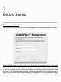
Registering InstallerPro™
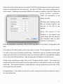
Upon startup for the first time, the user will be presented with the following registration window:
Before InstallerPro can be used it must first be purchased and registered with a valid license
key. To obtain a license key please contact Just Add Software or your local authorized representative. If the computer is connected to the Internet, the fastest way to request a license code is
to enter your name and e-mail address in the spaces provided (required for registration). Once
this is done, the “Send Registration Request” button will be enabled. Click this button and an email will be sent to Just Add Software requesting a license code. Once your purchase has been
verified, a license code will be provided via e-mail. Verification or purchase and providing a li-
8
cense key may take up to 24 hours. Requests are responded to as quickly as possible. If your
license code is needed right away, please contact [email protected] and explain
your situation and we will try to expedite the process.
InstallerPro™ is a subscription based product. The initial purchase provides for one year of updates and technical support. After the first year, a renewal license will need to be purchased in
order to continue to receive updates and technical support. If you choose not to update, the software will continue to function but you will not be eligible for software updates or technical support. When a valid registration code is entered, a message with your subscription expiration
date will be displayed. You can also find your expiration date on the “About” window of the software or by opening the Registration window (under the File menu).
To renew your subscription to InstallerPro, open the registration window and enter the new license key you received when subscribing. If you attempt to enter a key that is older than a year,
you will be notified that it is not a valid key for the current version of the software. Once a valid
key is entered, your subscription will be extended for another year.
Demo Mode:
A new feature of InstallerPro 2 is “Demo Mode.” In demo mode you can take a look at the program and try out all features except for actual communication with the switch or devices. To enter Demo mode, enter “DEMO” is the license key.
Out of Box Switch Configuration
When the managed switch is initially installed or has a factory reset performed, it is not in a state
that is fully compatible with the Just Add Power HD over IP™ video distribution system. Typically, getting the switch to operational status would require the user to connect to the console
port of the switch via RS-232 serial cable. A terminal session would then be opened and an initial switch configuration performed by manually typing configuration commands or sometimes
following set-up wizards on the switch. This is a time consuming task and prone to error. InstallerPro™ automates this process, and in just a few minutes, the entire video matrix will be programmed for optimal performance. For multiple site installations using similar configurations at
each site, programming of the switch can be done in seconds.
InstallerPro™ uses RS-232 serial communications to communicate with the switch. Some
switches will require the use of a “null modem” or crossover cable. For brand new switches, the
correct serial cable should be included in the box.
InstallerPro™ 2.0 has several options for configuring the switch. The most basic option is what
is called an “easy configuration.” When this option is selected, the switch can be rapidly and
easily set up for standalone operation using RS-232 control. This option only configures the
VLANs and the switch ports that are using the Just Add Power devices. No switch user name
or IP address configuration is performed.
If the “Easy Configuration” selection is not chosen, then the user can then configure the switch
for standard layer 2 mode of operation or the advanced layer 3 mode of operation. The layer 3
mode is not supported on all switches and is a more complex and advanced setup. The advan9
tage of operating in the layer 3 mode is that all Just Add Power hardware devices are now directly accessible via TCP/IP connections.
InstallerPro™ also has an advanced Just Add Power Hardware configuration tab that when selected allows viewing the available devices on the network. The user can then select to change
the device IP address, change serial port options, reset the unit to factory default and update device firmware. Firmware updates can be performed on multiple devices simultaneously.
Lastly, InstallerPro 2.0 features a layer 3 hardware configuration utility. This utility is available
once a switch has been configured for layer 3 operation. This utility will allow automatic configuration of Just Add Power HD/IP™ devices and their IP addresses based on either the published
Just Add Power best practices or on the users own configuration. The utility will also allow automatic firmware updates of all devices on the network. This is a very advanced utility and the procedures outlined in this manual must be followed in order for this utility to properly work.
10
2
Easy Configuration
InstallerPro™ 2 eliminates the hard
work of configuring the managed
switch.
In order to function properly in the Just Add Power HD/IP™ network, the managed switch
used to control video switching functions must be configured properly. Using the steps detailed in this chapter, the CI can have the Just Add Power system up and running in minutes. This chapter will cover the Easy Configuration option. Standard Layer 2 configuration options are covered in Chapter 3. Layer 3 configuration will be covered in chapter 5.
11
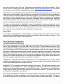
If the system where the switch will be used is going to operate solely as a standalone unit
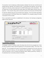
(i.e. not be connected to any other network) and controlled via RS-232 only, then the “Perform Easy Configuration” checkbox may be checked. Upon doing so, the following is displayed in the window:
To proceed, first select the desired serial port. Then select if the configuration is being
done for a Just Add Power 1G or 2G system. Finally, select the brand of switch being configured. The serial port baud rate will automatically adjust depending on the switch selected. If the standard baud rate needs to be overridden, it can be changed by either clicking on the values after the “Current Serial Port Settings:” label or it can be changed from
the edit menu.
Once the switch and serial port options are set, then proceed to enter the number of
sources and the number of screens in the fields provided. Once those fields have values,
the buttons beside them become active. Click each of these buttons to set up the names
of the sources or screens, the VLAN IDs and switch port numbers.
12
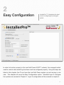
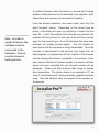
The example below shows an Easy Configuration setup for a
2G system using a Cisco SG300 switch with 5 sources and 4
screens.
Tip:
For Cisco SG series
switches, there is an
option to remove
login. This removes
the requirement to
login to the switch
when using RS-232
or Telnet
connections. This
options makes
control system
programming easier
but should only be
used in installations
where security is not
a concern.
To proceed to the next step in the configuration, click on the
Set Up Sources button in the software. A new window will
then open that looks as below.
13
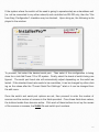
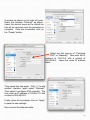
Enter the names of the sources, the desired VLAN ID and the physical switch port number
where the transmitter will be connected. For layer 2 VLANs, any number greater than 1
can be used. If deleting any existing VLANs on the switch is desired, check the “Delete Existing VLANs” checkbox.
When all information is entered, click OK.
Similarly, when clicking on the
Set Up Screens buttons, the
window on the left is presented.
Enter the names of the
Screens in the spaces provided along with the physical
port numbers used by each
receiver in the system.
Once all information is entered, click on OK to go back to the Switch Configuration Window.
Once back at the main screen, a few more options remain. The configuration can be saved
to a file so that it can be easily recalled later. InstallerPro uses a standard comma separated value text file for this information that can be easily edited in a spreadsheet application or other text editing software. See the appendix for details on the file format.
Finally, when everything is ready, click on the “Configure Switch” button. The proper commands will be sent to the switch and the output shown on the switch console on the right
hand side. The console window is interactive and manual commands can be sent to the
switch right from the window.
Congratulations - The switch is now set up and running and all video screens are set to
the very first source.
14
3
Standard Layer 2 setup
Configuring the switch for a standard switch configuration is very similar to that used with
the easy configuration discussed in the last chapter. This time there are more options to
choose from and change such as the switch’s IP address, switch user name and password and switch operation mode (Layer 2 or Layer 3). The standard configuration switch
page looks as shown below.
As in the case of
the easy configuration, select the serial port being used
along with the Just
Add Power hardware version and
brand of switch.
In this setup, an IP
address is required
to be entered.
If
the switch is going
to be operating in a LAN
environment, be sure to get an available IP address from the network administrator. If the
switch will be used in a standalone network and controlled either via TCP/IP or via RS232, then any IP address desired can be used. The fields for the IP address and subnets
will enforce proper IP address formation so that an incorrect or invalid address format cannot be used.
15
If the switch has a default user name and password those are automatically entered upon
selecting the switch. If the existing user name and password on the switch is different
from what is shown, then enter those values. To change the user name or password on
the switch to something different from its current value check the appropriate check box
to change the user name or password. If those boxes are checked, during the configuration, the user will be prompted to enter the new user name and password.
Once all of the network and user information is configured for the switch, enter the number
of sources and screens in the provided fields. A completed screen is shown below.
In the example shown, the “Using Stacked Switches” option is selected.
If a stacked
switch configuration is being used, be sure to check this so that the proper stack numbers can be specified when assigning ports to the transmitters and receivers.
When using stacked switches and receivers, the source and screen setup windows add a
new column where the stack number of the switch is entered.
These screens for the
above example are shown on the next page.
16
17
Once the sources and screens are set up, click the Configure
Switch button to program the switch. The console window on
the right hand will show the output from the switch as the commands are sent.
Sometimes, the
switch output on the
console will show
things like
“Unrecognized
Command” or
similar. Many times
this is OK as
InstallerPro
sometimes sends
commands that are
not necessarily
needed to ensure
that it is at the
proper command
level. If there are an
excessive number of
these in the output,
there may be an
issue so please
contact Just Add
Software if you see
that.
Once the switch is configured, all screens will be assigned to
the VLAN ID of the first source.
If trouble occurs during configuration of the switch, click in the
console view and type ctrl-a (command-a in OS X) to select all
the text, then ctrl-c (command-c in OS X) to copy the text to
the clip board. Then paste that text into an e-mail and send it
to [email protected]. We can generally spot what
is wrong fairly quickly and get back with a solution.
18
4
Hardware Configuration
InstallerPro 2 features several very powerful options for configuring Just Add Power 2G devices. The user is able to safely modify the IP address of the hardware, update serial port
configurations or update the firmware of every device on the network. This chapter will discuss these capabilities and explain how to perform each operation.
The InstallerPro 2 Hardware Configuration tab features a browser window where the user
can view all of the devices on the network and select operations to be performed on each
device. Please note that in order to browse devices on the network that Bonjour must be
installed on the computer being used. If the computer is running OS X, then Bonjour is already installed. If the computer is running Windows, then if Bonjour is not installed, a notice will be displayed with a link to where the software can be downloaded.
Just Add Power devices can be directly connected to the ethernet port of the computer
doing the configuration. In order for a successful connection to the device, the computer
must have an IP address in the same IP range as the hardware device. InstallerPro is unable to set the IP address of the computer. Please refer to the appendix of this manual for
instructions on changing the computer’s IP address. If the computer sees the device and
is able to connect to it, the device will show in the window and the information will be displayed in bold type-face. If the computer sees the device but is unable to connect, the
type-face will be normal.
Once connected, the device will display its name, IP address, firmware version and current
telnet port used for the connection. Some firmware revisions of Just Add Power devices
use telnet port 24 for the connection, while most newer revisions use port 23. InstallerPro
determines the best port for connection automatically.
19
If connection to and configuring multiple devices is desired, then the user must first put all
desired devices manually into the same VLAN. If transmitters and receivers, will be mixed
together for this step, please disconnect the HDMI cables going to the transmitters. This
will cause them to stop transmitting the video stream and enable easier discovery and configuration. The computer being used must also be placed onto this same VLAN and have
the same IP address range as the Just Add Power hardware. All of the VLAN manipulation
can be performed in the Switch Setup tab of InstallerPro 2 by manually typing the switch
commands into the console.
Once a successful connection is established to the devices, the hardware configuration
page is shown as below.
Programming a custom IP:
To program a custom IP address, select the device from the list to be programmed. Enter
the new IP address, subnet mask and gateway IP in the spaces provided. Then click “Configure IP.” The commands will be sent to the hardware to change the IP, the box will be rebooted and once it’s back up, the new address will be displayed. Proper IP address formats are enforced in the IP, subnet and Gateway fields, thereby preventing “bricking” of
the hardware due to incorrectly entered information.
20
If returning to the default self-configured IP address is desired (in the 169.254 IP address
space), click the “Use Auto Configured IP” box and click the Configure IP button. The default IP configuration will then be applied and the box rebooted.
Note that upon reboot, the box may not connect (ie: it will be shown in normal type face).
This is to be expected as the computer may no longer have the correct IP address space
assigned to communicate with the box.
Only a single box can have its IP address updated at a time. If more than one box is selected, a warning will be presented.
Changing Serial Port Settings:
The external serial port of the Just Add Hardware devices can be configured by selecting
the hardware desired, and then making the adjustments in serial port mode, data rate, etc.
A full factory reset of the device can also be performed.
As with setting the IP address, only one box can be configured at a time and the user will
be warned if more than one box is selected.
Updating Firmware:
InstallerPro 2 has a very powerful firmware updating utility. By displaying the firmware revision in the browser display, it is easy to see if there are one or more devices on the network that have mis-matched firmware. Previous methods of updating firmware required
the user to manually connect to the internal web page of each Just Add Power device, select the firmware update page, open the firmware file and begin programming. This utility
inside InstallerPro 2 allows the firmware files to be loaded once and the software will simultaneously load the firmware to all devices selected. This will save significant amounts of
time updating the firmware for large networks.
21
To update firmware, select the device or devices (for firmware
update multiple devices can be selected) to be updated. Both
transmitters and receivers can be selected together.
Once the desired selections have been made, click the “Update Firmware” button.
Depending on the device type se-
lected, a file dialog will open up prompting to select the firmware file. If both transmitters and receivers are selected, the
Note - in order to
update firmware, the
software must be
connected to the
hardware - the text
must be shown in
bold type face.
software will first prompt for one type of file and then prompt
again for the second type. Once the firmware files have been
selected, the update process begins.
Text will indicate for
each device that the firmware is being downloaded. Once the
firmware is downloaded to the devices, they begin their update progress. A progress bar will then display in the firmware
column showing the amount completed in the process. Once
each device finishes its firmware update, the device will then
reboot and upon rebooting the new firmware revision will be
displayed. Please note that receivers take longer to update
than transmitters. The picture below is an example of 11 devices (7 transmitters and 4 receivers) being updated simultaneously. Note the different rates of progress of the updates on
the devices.
22
Once all hardware programming is completed, click on the Switch Setup tab to go back to
the switch utility. Then enter the commands (or re-program the switch) to put all ports
back into their proper VLANs.
Additional Options:
By selecting a device and
right clicking, a pop-up
menu is presented with
the following options:
Show device MAC address, Open Device Webpage, Update Device
Firmware and Restore
Factory Defaults.
If the
device is not connected,
an option to attempt a
connection to the device
is shown instead.
23
5
Layer 3 System Configuration
One of the most powerful aspects of InstallerPro 2 is its ability to completely configure a
Just Add Power system for Layer 3 operation. Layer 3 operation allows full TCP/IP access to all Just Add Power devices from the LAN regardless of what video VLAN the devices are currently utilizing. By setting up a Layer 3 system, CIs can now program their
control systems to directly communicate via IP with the serial ports on the Just Add Power
hardware. With Just Add Power’s 2G+ lineup, HDMI-CEC commands can be sent directly
to the on-board CEC processor.
While Layer 3 configuration is extremely powerful, it is also more involved and difficult to
set up. InstallerPro 2 aims to make this setup as easy as possible provided the specific
steps laid out in this manual are followed. Please be sure to read and understand this
chapter fully before attempting to configure a layer 3 system.
Parts of the Layer 3 Configuration
There are two parts to the Layer 3 configuration. This first is to set up the switch for Layer
3 operation. The second step is to configure the Just Add Power hardware. InstallerPro
allows the user to set up just the switch or to set up first the switch and then the hardware.
If you wish to configure the hardware for Layer 3 mode, the switch must be configured
first.
Configuring the Switch for Layer 3
To set up Layer 3, first select the 2G system in InstallerPro 2 (1G systems are not able to
take advantage of the layer 3 environment). Then select the desired switch brand. Note
24
that the selection of switches available has changed as not all switches support Layer 3
operations.
Now the switch first needs to be put into what is called “router mode.” Most Layer 3 capable switches do not come with this mode enabled.
If the user is configuring a Cisco
SG300 or SG500 switch, InstallerPro 2 will display a button that will send commands to
the switch to put it in router mode. Establish an RS-232 connection to the switch and
then click the “Set Switch to Router” button. The switch will receive the commands and
then reboot.
Once the switch comes back to it’s normal state (the “>” or “#” or login
prompt), it is ready for the next step in configuration. If the switch being set up is a different model than the SG300 or SG500, the user will need to enter the required commands
manually. Please consult the manual for the switch being used for the commands to perform this setting on the switch.
Once the switch has rebooted and is in router mode, proceed to set up the switch just like
would be done for any other configuration. Enter the number of sources and screens and
then click on “Configure Sources.” This is where things begin to change.
When “Configure Sources” is selected in Layer 3 configuration mode, new fields are
added to the Source Configuration window that opens. There are now new fields for assigning the IP address, Subnet and Gateway to the VLAN IP. By default, the “Use Just
Add Power Best Practices” checkbox is selected. By utilizing this feature, all of the IP addresses, subnets and gateways for each VLAN will be automatically filled in.
25
Please also note that in addition to your normal sources, two new VLANs have been set
up. These are named “LAN” and “All JAP devices” respectively. When using best practices, these have been assigned to VLANs 2 and 10 respectively. It is VERY IMPORTANT
that in the LAN fields, the user enters the switch port on which the computer or control system will be connected to the switch. Layer 3 control will not properly function with out
this.
Once the sources are all configured click OK to be taken back to the main screen. Then
click on Configure Screens. Screen configuration is the same as it is for Layer 2.
Once the screens are set up, click OK. Now we are ready to program the switch. Click
the configure switch button and the switch will be properly configured for Layer 3 operation.
When the switch configuration is complete, a new tab will appear called “Layer 3 Hardware Configuration.”
This tab will be used to program the Just Add Power pieces for
Layer 3 operation. But before clicking on this tab, it is imperative that the following procedure be followed:
Configuring the Just Add Power hardware for Layer 3 operation:
In order to detect and program the hardware devices for Layer 3 operation, all devices
must temporarily be on the same VLAN and the computer running InstallerPro must be
configured with the correct IP address and subnet values. Since all devices are temporarily on the same VLAN, none of the transmitters can be transmitting a video stream as it will
interfere with device discovery and programming.
Follow these steps for configuring for Layer 3 BEFORE clicking the “Layer 3 Hardware Configuration” tab:
a.) connect all Just Add Power receivers and transmitters to be configured to the
ports defined during the programming of the switch. But do NOT connect any HDMI cables. Please make sure all HDMI cables are disconnected - particularly from the transmitters. WIth the HDMI cables connected, the transmitters will start streaming and this will
cause problems.
!
!
26
b.) On the computer, turn of ALL network connections except the ethernet connection being used to connect to the switch. The ethernet connection from the computer
needs to be connected to the port that was defined for VLAN 2 or the LAN during the
setup phase.
c.) Make sure that the computer has an IP address in the same subnet as was
programmed for VLAN 2 on the switch. So if VLAN 2 has a 192.168.1.xxx address with
subnet 255.255.255.0, then the computer ethernet address needs to be assigned to that
same network and subnet space. Please leave the gateway IP blank. For information on
setting IP addresses on the computer, please refer to the section entitled, “Setting IP Addresses on the Computer.”
d.) In addition to step "c" above, the computer will also need two additional IP addresses added to the network card (this is temporary only). Please add the address of
10.0.10.2 (if not using Just Add Power “best practices” enter the correct address space
for communicating with the devices) with subnet of 255.255.0.0 and add the address
169.254.1.2 with subnet 255.255.0.0. Leave the gateway IPs blank. These multiple IP addresses will allow communication with the switch and the devices. For information on adding these addresses see the section below titled, “Setting IP Addresses on the Computer.”
e.) Once the steps above are complete, and the computer is connected to the
switch with both RS-232 and ethernet, then and only then click on the Layer 3 Hardware
Configuration tab.
27
Setting IP Addresses on the Computer:
OS X:
To set an IP address on a Macintosh computer running OS X, click on the System Preferences icon in the Dock. System preferences will open and look like the image
shown on the left.
Click on the Network icon under the Internet
and Wireless section. The network settings
panel will then open as shown below (to
change settings, it may be necessary to click
the lock icon at the bottom and enter the administrator password).
First select the “Ethernet” option. (If no
“Ethernet” option exists (e.g. using a
MacBook Air), then a USB to Ethernet
adapter will need to be obtained.)
Select “Manually” from the “Configure
IPv4” pop-up menu.
Enter the IP address to be an address in
the subnet of what was configured for the
LAN port on the switch. Enter the subnet
mask as was configured for the LAN port
on the switch. Leave the Router
field blank.
Next, click the “+”
button in the lower left corner. This will create a new connection
interface for the next IP address needed. This is only temporary.
28
A window as shown on the right will open.
Select the interface “Ethernet” as shown.
Leave the service name as the default as
this will be removed once the procedure is
complete. Once this is selected, click on
the “Create” button.
Select the first pop-up of “Configure
IPV4” to “Manually.” Now enter the IP
address of 10.0.10.2 with a subnet of
255.255.0.0. Leave the router IP address
blank.
Then repeat this step again. Click “+” to add
another interface, again select “Ethernet.”
Then select to configure IPV4 manually. This
time enter an IP address of 169.254.1.2 with
a subnet of 255.255.0.0.
Finally, when all is complete, click on “Apply”
to save the new settings.
Now connect the ethernet cable.
29
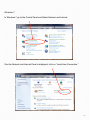
Windows 7:
In Windows 7 go to the Control Panel and Select Network and Internet:
One the Network and Internet Panel is displayed, click on “Local Area Connection.”
30
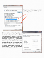
In the screen that opens up, select Internet Protocol Version 4 (TCP/IPv4). Then
click on Properties.
This next window contains the settings for
the main network connection. This is possibly already configured or set up. Select
“Use the following IP address.” In the example on the right, the computer was set to an
address of 192.168.1.21.
This address
needs to be in the same IP address range
that is configured for VLAN 2 on the switch
whatever that may be. Set the subnet mask
to 255.255.255.0 (or whatever is in use for
the LAN connection on the switch). Leave
the default gateway and DNS server addresses blank.
Once this is complete,
please click the “Advanced” button.
31
This screen will allow addition of the extra IP addresses needed to communicate with the
hardware. To add the extra IP addresses, click on the Add button.
Enter the address of 10.0.10.2 with a
subnet mask of 255.255.0.0. Then click
Add. When that window closes, click
the Add button in the Advanced TCP/IP
Settings window a second time. In the
window that comes up enter the address 169.254.1.2 with a subnet mask
of 255.255.0.0. Then click Add. Now
back in the Advanced Settings Window,
click “OK.”
That window will close.
Then in the Internet Protocol Version 4
window click OK. That window will now
close. Then click OK in the local area connection properties window. Now all addresses are configured and Layer 3 configuration can begin. After the hardware
is configured and programmed for Layer
32
3, remember to come back to these windows and undo the changes. Remove the extra IP
addresses by selecting the address and clicking the “Remove” button in the Advanced
TCP/IP settings window.
4.) Layer 3 Hardware configuration:
Once this tab is selected after the steps described above, the software will log into the
switch via ethernet and start discovering what MAC addresses are connected to the ports
on the switch. In addition, it will also program the switch so that ALL devices are temporarily on VLAN 2. We need to do this as Bonjour discovery doesn't work easily over layer 3
router interfaces!
Once the Mac addresses are discovered, the software
will begin discovering the hardware
boxes and connecting to them. They
boxes will show up
at the proper ports
where they are connected at the
switch. So we've
not only discovered
the boxes, we know
where they are
plugged in! Now
you can either
manually edit the IP
address fields or click
the best practices checkbox. When you do that, all the IPs and subnets of all the boxes
will be changed to the best practices settings defined by Just Add Power. In the example image shown above, seven transmitters and 4 receivers have been discovered and displayed at their previously configured switch ports. Two of the devices have incorrect IP addresses and some of the transmitters will need to have their IP addresses
changed as they are now on different VLANs. The next image shows the new IP address
configuration once the Best Practices checkbox is checked.
33
To program the hardware
then click the "Program Hardware" button. The IP addresses will be updated and
the boxes rebooted. As they
come back online, they will
re-appear in their proper
places.
In the image at the right, the
h a r d w a r e h a s b e e n p r ogrammed and the devices are
all being rebooted. Once they
come back online as shown in
the image below, the IP addresses are all changed to the
best practices configuration.
If any firmware updates are
needed, that can be performed here as well. Just select the box or boxes to update and then click the Update Firmware button and follow the steps. It's very similar to what is described in the
previous chapter.
Once all this is done, do NOT
just quit the program. Instead, click back to tab 1. You'll see a scrolling text in the
34
console window. We are setting things back to their proper VLANs for correct operation.
Now, the system is fully programmed for layer 3 operation - switch AND hardware. Now,
go and remove the 10.0.10.2 and 196.254.1.2 IP addresses from your computer. And set
the proper gateway IP for your LAN IP. To remove the addresses in OS X, go to system
preferences and click on Network as explained earlier. Select the entry to be removed and
click the “-” button down at the bottom of the list. In Windows, follow the previous instructions to get to the “Advanced TCP/IP Settings” window. Then select the address to be removed and click the “Remove” button. Then click on OK in each window to close the windows.
35
Appendix - InstallerPro File Format
The configuration file for InstallerPro™ is a comma delimited text file (CSV) that can be edited manually in any text editor or spreadsheet program such as Excel. As a custom installer, a master spreadsheet template can be kept that is easily editable in a user friendly
environment such as Excel. To use the configuration in InstallerPro™ the spreadsheet is
simply exported as a CSV file. It can then be loaded into InstallerPro™ via the Load Configuration File button. This can make it easy to rapidly deploy multiple installation sites.
File Format:
Any lines beginning with a “!” will be interpreted by InstallerPro™ as a comment line and
will not be read. Such a line can be easily used to make the configuration file more readable and understandable. An unlimited number of comment lines can be in the file.
Please note that InstallerPro™ does not save these comments. So any configuration file
written over by InstallerPro™ will lose the comments that may have been added.
Each line in italics below is a line in the CSV.
G1 or G2 - Use G1 for a 1st Gen System or G2 for a 2nd Gen system
Number Of Sources
Number of Screens
Switch IP Address
Switch Brand
Switch UserName
Switch Password
Switch TCP Connection Port (almost always port 23)
Stacked Configuration - True or False
Instant Receiver Configuration - True or False (usually false)
Source #1 Name,Physical Ethernet Port,VLAN ID,Stack ID,Instant Port,Instant stack
Source #2 Name,Physical Ethernet Port,VLAN ID,Stack ID,Instant Port,Instant stack,Layer3 IP Address, Layer3 Subnet
Source #3 Name,Physical Ethernet Port,VLAN ID,Stack ID,Instant Port,Instant stack, Layer3 IP Address, Layer3 Subnet
.
.
.
36
LAN,Physical Ethernet Port,VLAN ID, StackID,InstantPort,Instant Stack,LAN IP, LAN Subnet
All HDIP Devices,,10,,,,ALL DEVICES IP,ALL DEVICES Subnet*
Source #x Name,Physical Ethernet Port,VLAN ID,Stack ID,Instant Port,Instant stack
Screen #1 Name,Physical Ethernet Port,Stack ID
Screen #2 Name,Physical Ethernet Port,Stack ID
Screen #3 Name,Physical Ethernet Port,Stack ID
.
.
Screen #y Name, Physical Ethernet Port,Stack ID
Here "x" and "y" are the final source and screen numbers.
Stack ID is the stack number in use. If the installation does not use stacked switches,
then this value should be 0.
Instant Port is the port for the instant receiver being used. If instant receivers are not being used, then this value should be 0. Instant receivers are only used in rare cases on 1G
systems. Usually this field will be left blank.
Instant Stack is the stack number for the instant receiver. If instant receivers or stacked
switches are not being used, then this value should be 0.
Layer3 IP Address and Layer3 Subnet fields need only be filled out if the switch has been
configured in Layer 3 mode.
*LAN line is optional for Layer 2 configurations, but required for Layer 3. The All HDIP Devices line can be removed for Layer 2 configurations.
Examples:
37
For a First Generation system with 10 sources and 5 screens not using stacked switches
or instant receivers we would have the following:
G1
10
5
192.168.1.2
Cisco SG300 Series
cisco
cisco
23
False
False
Tivo HD1,1,10,0,0,0
Tivo HD2,3,11,0,0,0
Tivo HD3,5,12,0,0,0
AppleTV,7,13,0,0,0
Vudu XL,9,14,0,0,0
Boxee,11,15,0,0,0
BluRay1,13,16,0,0,0
BluRay2,15,17,0,0,0
SecurityCam1,17,18,0,0,0
SecurityCam2,19,19,0,0,0
Family Room,2,0
Living Room,4,0
MasterBedroom,6,0
Guest Bedroom,6,0
Den,10,0
38
For the same configuration using stacked switches we would have:
G1
10
5
192.168.1.2
Cisco SG500 Series
cisco
cisco
23
True
False
Tivo HD1,1,10,1,0,0
Tivo HD2,3,11,1,0,0
Tivo HD3,5,12,1,0,0
AppleTV,7,13,1,0,0
Vudu XL,9,14,1,0,0
Boxee,11,15,1,0,0
BluRay1,13,16,1,0,0
BluRay2,15,17,1,0,0
SecurityCam1,17,18,2,0,0
SecurityCam2,19,19,2,0,0
Family Room,2,1
Living Room,4,2
MasterBedroom,6,1
Guest Bedroom,6,2
Den,10,2
39
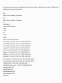
Let’s assume the same configuration but this time using a G2 system in Layer 3 Mode and
adding in some comment lines:
G2
!Next line is number of sources
10
!Next line is number of screens
5
192.168.1.2
Cisco SG300 Series
cisco
cisco
23
False
False
!Source Content is below
Tivo HD1,1,11,0,0,0,10.0.11.1,255.255.255.0
Tivo HD2,3,12,0,0,0,10.0.12.1,255.255.255.0
Tivo HD3,5,13,0,0,0,10.0.13.1,255.255.255.0
AppleTV,7,14,0,0,0,10.0.14.1,255.255.255.0
Vudu XL,9,15,0,0,0,10.0.15.1,255.255.255.0
Boxee,11,16,0,0,0,10.0.16.1,255.255.255.0
BluRay1,13,17,0,0,0,10.0.17.1,255.255.255.0
BluRay2,15,18,0,0,0,10.0.18.1,255.255.255.0
SecurityCam1,17,19,0,0,0,10.0.19.1,255.255.255.0
SecurityCam2,19,20,0,0,0,10.0.20.1,255.255.255.0
LAN,24,2,0,0,0,192.168.1,255.255.255.0
All HDIP Devices,,10,,,,10.0.10.1,255.255.255.0
Family Room,2,0
Living Room,4,0
MasterBedroom,6,0
Guest Bedroom,6,0
Den,10,0
40
This file can be edited in a spreadsheet like Excel and saved as a comma delimited text
file (note that some spreadsheet programs add a trailing comma at the end of each line.
Excel does not do this and so is recommended). All information can be entered ahead of
time. Then to load the file, go to the configuration window and click on "Load Configuration File." You'll then be able to pick the file you want to load and it will then make the entries in that file the current configuration. 41
Appendix B - Changing the IP Address on the
computer
OS X:
To set an IP address on a Macintosh computer running OS X, click on the System Preferences icon in the Dock. System preferences will open and look like the image
shown on the left..
Click on the Network icon under the Internet
and Wireless section. The network settings
panel will then open as shown below (to
change settings, it may be necessary to click
the lock icon at the bottom and enter the administrator password). If a manually configured address is to be used, select “Manually”
from the “Configure IPv4” pop-up menu.
Then enter the appropriate IP address, subnet and gateway. If an automatic configuration is desired using DHCP, select “Using
DHCP” from the pop-up menu. Then click
Apply.
42
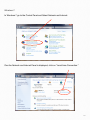
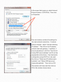
Windows 7:
In Windows 7 go to the Control Panel and Select Network and Internet:
One the Network and Internet Panel is displayed, click on “Local Area Connection.”
43
In the screen that opens up, select Internet
Protocol Version 4 (TCP/IPv4). Then click
on Properties.
This next window contains the settings for
the main network connection. If manual
setup is desired, select “Use the following
IP address.” Then fill out the IP address,
subnet mask and gateway. In addition, it
may be necessary to click the “Use the following DNS server address” and fill out the
appropriate entries there. If and automatic
configuration using DHCP is to be used
the click on “Obtain and IP address automatically” and “Obtain DNS server address automatically.” Then click on OK.
The window will close and then click on
OK in the window shown above.
44
Bonjour
From Wikipedia (http://en.wikipedia.org/wiki/Bonjour_(software))
Bonjour is Apple's implementation of Zero configuration networking (Z
group of technologies that includes service discovery, address assignm
hostname resolution. Bonjour locates devices such as printers, other c
and the services that those devices offer on a local network using mul
main Name System (mDNS) service records.
The software comes built-in with Apple's OS X and iOS operating syst
jour can also be installed onto computers running Microsoft Windows.
components may also be included within other software such as iTune
fari.
Related Glossary Terms
Drag related terms here
Index
Find Term
Chapter 4 - Hardware Configuration
Chapter 4 - Hardware Configuration
Layer 2
For a description of Layer 2, please visit: http://en.wikipedia.org/wiki/L
Related Glossary Terms
Drag related terms here
Layer 3
For a description of Layer 3, please visit: http://en.wikipedia.org/wiki/L
Related Glossary Terms
Drag related terms here
Stacked switch
A stacked switch is a configuration where two or more switches are in
nected but function as a single entity. Since each switch has a duplica
physical ports, each switch is represented by a “stack” number that is
identify which switch the port belongs to. Stack numbers generally be
and in some switches can go as high as 8 or even 16. The advantage
stacked configuration is that very large networks can be built that can
trolled from a single point. The connection between the switches is us
via high speed fiber optic interconnects or high speed stacking modul
provides for the maximum amount of data bandwidth between switch
Related Glossary Terms
Drag related terms here
VLAN
VLANS or Virtual Local Area Networks are isolated network segments
on the network switch. Devices assigned to a VLAN can only see and
by other devices on the same VLAN. In the Just Add Power network a
ture VLANs are used to isolate each transmitter stream and receivers a
between VLANs when switching sources is desired. Using this sort of
ton, multiple switch ports can be simultaneously and instantaneously
new video sourc.
Related Glossary Terms
Drag related terms here