1
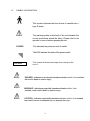
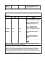
CHAIRS AND STANDS INSTALLATION & OPERATING MANUAL This manual contains installation and operating instructions for the following units: Deluxe 2 Stand Deluxe 2 Non-Console Stand Product Number 1206 Product Number 1213 Encore Stand Encore Stand Product Number 1290 Product Number 1291(Full PERC Programmable) Marco Tilt Chair Product Number 1262 Encore Chair Product Number 1280 (Manual) Product Number 1220 (Automatic) 1 Contents Introduction Section 1 Outline Classifications Symbol Information Unpacking Specifications 1.1 1.2 1.3 1.4 1.5 Safety Section 2 EMC (Electro Magnetic Compatibility) Stands 2.1 Section 3 Installation Operation 3.1 3.2 Chairs Section 4 Installation/Operation Marco Tilt Chair Encore Manual Chair Encore Automatic Chair 4.1 4.2 4.3 Care & Maintenance Section 5 Operation of Optional P.E.R.C. Section 6 2 Introduction Section 1 1.1 OUTLINE OF THE INSTRUMENTS The Marco series of Chairs and Stands are the results of many years of extensive product research and engineering. This manual provides information on installation, operation and other pertinent information regarding operational safety, general care and maintenance. Please utilize this detailed information or contact your authorized Marco distributor for technical support, parts and service. To locate an authorized Marco Distributor go to the following web site: http://marco.com/classical/12.html 1.2 CLASSIFICATIONS [Form of protection against shock] The Marco Chairs and Stands are Class 1 devices. A Class 1 device is an instrument in which protection against electric shock does not rely solely on basic insulation. A Class 1 device includes additional safety precautions that provide for connection of accessible conductive parts to a protective earth grounding terminal. [Degree of protection against shock] Marco Chairs and Stands are classified as type BF devices. A type BF device provides an adequate degree of protection against electric shock, particularly regarding the following: 1) Allowable leakage currents 2) Reliability of the protective earth ground connection (if applicable) [Degree of protection against liquid entry] Marco Chairs and Stands are classified as normal devices, and as such provide only minimal protection against liquid intrusion. The enclosures of all Marco Chairs and Stands are not completely waterproof. Avoid immersion of any type. [Degree of protection against flammability] Marco Chairs and Stands are classified as devices not suitable for use in a potentially flammable environment; therefore do not operate the device near flammable type materials. 3 1.3 SYMBOL INFORMATION This symbol indicates that the device is classified as a type B device. This warning symbol on the body of the unit indicates that normal precautions should be taken. Please refer to the operator’s manual before operating the unit. POWER This indicates the power on and off switch. This LED indicates the state of the power switch. T10L250V This symbol indicates the proper fuse ratings of the device. DANGER - Indicates an imminently hazardous situation which, if not avoided, will result in death or serious injury. WARNING - Indicates a potentially hazardous situation which, if not avoided, could result in death or serious injury. CAUTION - Indicates a potentially hazardous situation which, if not avoided may result in minor or moderate injury or property damage. 4 1.4 UNPACKING All Marco Chairs and Stands are shipped in individual containers with all Chairs and Stands packaged the same respectively. The unit comes complete with tools for installation, power cords, touch-up paint, and all accessories necessary for assembly of the basic unit. (Optional items are shipped separately.) The simplest method of unpacking is to place the shipping container in the general area where the unit is to be used. Ensure the area for placement is level. Remove the strapping material from the crate. Lift the carton straight up from the wooden base and turn it upside down. Carefully check for any items, which may still be connected or lodged inside of the shipping carton. Carefully remove the protective coverings and place them in an area where they will not present a slip hazard. Unpack the installation tools and accessory boxes for easy access during assembly. After removing the wood anchor slats slide the unit off the wooden base onto the floor. 1.5 SPECIFICATIONS 1) Power Source: 2) Power Consumption: 3) Fuse Ratings: AC 100V/120V (+/- 10%) 50/60Hz 120VA Model 1206: a) b) c) d) T10L250V = Mains 10 amp fuse (2 REQ’D) T5L250V = Counter-balanced Slit Lamp Arm 5 amp fuse T1L250V = Well Charging Circuit 1 amp fuse T5L250V = Room Light Circuit 5 amp fuse Model 1290/1291: a) e) f) g) T10L250V = Mains 10 amp fuse (2 REQ’D) T5L250V = Binding Post 5 amp fuse T1.6L250V = Logic, Power Distribution Control 1.6 amp fuse T2L250V = Stand Lamp 2 amp fuse Model 1213: a) T10L250V = Mains 10 amp fuse (2 REQ’D) Model 1262/1280/1220: a) T8L250V = Mains 8 amp fuse (2 REQ’D) 4) Product Weight: Model 1206/1290/1291: a) Gross Weight = 170 kg (374 Lbs) b) Net Weight = 150 kg (330 Lbs) Model 1213: a) Gross Weight = 158 kg (347.6 Lbs) b) Net Weight = 100 kg (220 Lbs) Model 1220/1280: a) Gross Weight = 145.5 kg (295 Lbs) b) Net Weight = 115.5 kg (254 Lbs) Model 1262: a) Gross Weight = 160 kg (352 Lbs) b) Net Weight = 126 kg (277 Lbs) 5 SAFETY Section 2 CAUTION - Never disassemble or tamper with the inside of the instrument. This may result in electrical shock or instrument malfunction. - Be sure the electrical outlet meets the power requirement specification of the instrument. If the voltage is too high or too low, it may affect the performance of the instrument and may start an electrical fire. - Always remove the cord from the electrical outlet by holding the plug. Never pull on the cord, this can damage the internal wires and may result in a short circuit, electric shock or a fire. - If the internal wires of the power cord are exposed, the power to the instrument will be inconsistent or the plug will become extremely hot, indicating internal damage to the cord. If this occurs, remove the cord from the outlet immediately and contact Marco or you’re nearest authorized distributor. Otherwise the cord may cause an electric shock or fire. - Do not crush or squeeze the power cord with heavy objects or furniture. If the power cord is damaged, it may cause electric shock or fire. - Clean between the prongs of the power plug using a dry cloth every couple of months. If the plug is exposed to moisture or excessive dirt builds up on the prongs, a short circuit or fire could result. - If you observe strange odors or smoke being emitted from the instrument, turn OFF the instrument, disconnect the power cord immediately and contact Marco or your authorized distributor. - The instruments have been tested and found to comply with the limits for medical devices to IEC 60601-1 3rd Edition standards. These limits are designed to provide reasonable protection against harmful interference in a typical medical installation. These instruments generate, use and can radiate radio frequency energy and, if not installed and used in accordance with the instructions, may cause harmful interference to other devices in the vicinity. However, there is no guarantee that interference will not occur in a particular installation. If interference does occur, which can be determined by turning the instruments off and on, the following suggestions are provided to the user to correct the interference: - Reorient or relocate the receiving device. - Increase the separation between the instruments. - Connect the instrument to an outlet on a circuit different from that to which the other device(s) are connected. - Consult the manufacturer or field service technician for help. NOTE - Preferred Storage Conditions: Temperature: 10°c-40°c Humidity: 30% - 85% - Do not store the instrument in a place where it may be exposed to moisture or toxic chemicals. - Avoid storing the instrument in an area with excessive heat, humidity or dust. To preserve the Appearance of the instrument and avoid placing in direct sunlight. 2.1 EMC (Electro Magnetic Compatibility) The Electro Magnetic Compatibility Directive sets the essential requirements for electrical and electronic equipment that may disturb or even be disturbed by other equipment. The Marco Chairs and Stands covered in this manual comply with these requirements as tabled below. Follow the guidance on the tables for use of the devices in the electromagnetic environment. 6 EMC (IEC 60601-1-2:2001) Guidance and manufacturer’s declaration - electromagnetic emissions The Marco Chairs and Stands are intended for use in the electromagnetic environment specified below. The customer or the user of the Marco Chairs and Stands should assure that they are used in such an environment. Emissions test Compliance Electromagnetic environment - guidance RF emissions CISPR 11 Group 1 RF emissions CISPR 11 Harmonic emissions IEC 61000-3-2 Voltage fluctuations/ Flicker emissions IEC 61000-3-3 Class B Not Applicable The Marco Chairs and Stands use RF energy only for its internal function. Therefore, its RF emissions are very low and are not likely to cause any interference in nearby electronic equipment. The Marco Chairs and Stands are suitable for use in all establishments other than domestic and those directly connected to the public low-voltage power supply network that supplies buildings used for domestic purposes. Not Applicable Guidance and manufacturer’s declaration -- electromagnetic immunity The Marco Chairs and Stands are intended for use in the electromagnetic environment specified below. The customer or the user of the Marco Chairs and Stands should assure that it is used in such an environment. Immunity test Electrostatic IEC 60601 test level ±6 kV contact ±8 kV air Compliance level ±6 kV contact ±8 kV air Discharge (ESD) Electromagnetic environment guidance Floor should be wood, concrete or ceramic tile. If floors are covered with synthetic material, the relative humidity should be at least 30%. IEC 61000-4-2 Electrical fast transient/burst IEC61000-4-4 ±2 kV for power supply lines ±1 kV for input/output lines Surge ±1 kV IEC 61000-4-5 differential mode ±2kV common mode Voltage, dips, <5% UT short (>95% dip in UT) interruptions and for 0.5 cycle voltage 40% UT (60% dip in U1) variations on for 5 cycles power supply (30% dip in UT) input lines IEC 61000-4-11 for 25 cycles <5%UT (>95% dip in UT) for 5 sec ±2 kV Mains power quality should be that of a for power supply typical commercial or hospital lines environment. ±1 kV for input/output lines ±1 kV differential mode ±2kV common mode <5% UT (>95% dip in UT) for 0.5 cycle 40% U1 (60% dip in UT) for 5 cycles (30% dip in UT) for 25 cycles <5%UT (>95% dip in UT) for 5 sec 7 Mains power quality should be that of a typical commercial or hospital environment. Mains power quality should be that of a typical commercial or hospital environment If the user of the Marco Chairs and Stands requires continued operation during power mains interruptions, it is recommended that the Marco Chairs and Stands be powered from an uninterruptible power supply or a battery. Power frequency 3 A/m 3 A/m Power frequency magnetic fields should (50/60 Hz) be at levels characteristic of a typical magnetic field location in a typical commercial or IEC 61000-4-8 hospital environment. NOTE UT is the ac. mains voltage prior to application of the test level. Guidance and manufacturer’s declaration - electromagnetic immunity The Marco Chairs and Stands are intended for use in the electromagnetic environment specified below. The customer of the user of the Marco Chairs and Stands should assure that they are used in such an environment. Immunity test IEC 60601 test Compliance level Electromagnetic environment level guidance Conducted RF 3 Vrms 3 Vrms IEC 61000-4-6 150 kHz to 80 MHz 3 V/m (V1=3) 80 MHz to 2.5 GHz (E1=3) Radiated RF IEC 61000-4-3 Portable and mobile RE communications equipment should be used no closer to any part of the Marco Chairs and Stands, including cables, than the recommended separation distance calculated from the equations applicable to the frequency of the transmitter. Recommended separation distance d=1.2x √ P d=1.2x √ P 80 MHz to 800 MHz d=2.3x √ P 8OO MHz to 2.5 GHz where P is the maximum output power rating of the transmitter in watts (W) according to the transmitter manufacturer and d is the recommended separation distance in meters (m). Field strengths from fixed RF transmitters, as determined by an electromagnetic site survey,(a) should be less than the compliance level in each frequency range.(b) Interference may occur in the vicinity of equipment marked with the following symbol: 3 V/m NOTE 1 At 80 MHz and 800 MHz the higher frequency range applies. NOTE 2 These guidelines may not apply in all situations. Electromagnetic propagation is affected by absorption and reflection from structures objects and people. (a) Field strengths from fixed transmitters, such as base stations for radio (cellular/cordless) telephones and land mobile radios, amateur radio, AM and FM radio broadcast and TV broadcast cannot be predicted theoretically with accuracy. To assess the electromagnetic environment due to fixed RF transmitters, an electromagnetic site survey should be considered. If the measured field strength in the location in which the Marco Chairs and Stands are used exceeds the applicable RF compliance level above, the Marco Chairs and Stands should be observed to verify normal operation. If abnormal performance is observed, additional measures may be necessary, such as reorienting or relocating the Marco Chairs and Stands. (b) Over the frequency range 150 kHz to 80 MHz, field strengths should be less than 3 V/m. 8 Recommended separation distances between portable and mobile RF communications equipment and the Marco Chairs and Stands. The Marco Chairs and Stands are intended for use in an electromagnetic environment in which radiated RF disturbances are controlled. The customer or the user of the Marco Chairs and Stands can help prevent electromagnetic interference by maintaining a minimum distance between portable and mobile RF communications equipment (transmitters) and the Marco Chairs and Stands as recommended below according to the maximum output power of the communications equipment. Rated maximum output power of transmitter W Separation distance according to frequency of transmitter m 150 kHz to 80 MHz 80 MHz to 800 MHz 800 MHz to 2.5 GHz d=1.2√P d=1.2√P d2.3√P 0.01 0.12 0.12 0.23 0.1 0.38 0.38 0.73 1 1.2 1.2 2.3 10 3.8 3.8 7.3 100 12 12 23 For transmitters rated at a maximum output power not listed above, the recommended separation distance d in meters (m) can be estimated using the equation applicable to the frequency of the transmitter, where P is the maximum output power rating of the transmitter in watts (W) according to the transmitter manufacturer. NOTE 1 At 80 MHz and 800 MHz, the separation distance for the higher frequency range applies. NOTE 2 These guidelines may not apply in all situations. Electromagnetic propagation is affected by absorption and reflection from structures, objects and people. 9 STANDS Section 3 3.1 INSTALLATION CAUTION: ELECTRICAL SHOCK HAZARD. DO NOT APPLY POWER TO ANY PRODUCT UNTIL ALL ASSEMBLY AND INSTALLATION STEPS ARE COMPLETED. DO NOT OPERATE ANY PRODUCT UNLESS IT IS FULLY ASSEMBLED WITH ALL STANDARD ACCESSORIES AND COVERS IN PLACE. For the Encore and Deluxe 2 Stands find the instrument support pole and locate a positioning notch in one end. This is the bottom of the pole, which fits into the top of the stand. For the Encore Stands loosen the small hex socket set screws which hold the round painted cap onto the outside of the mounting hole and remove it in order to expose the locking hex socket set screws for the instrument pole. Loosen the two locking hex socket set screws. For the Deluxe 2 Stands remove the upper back panel to expose the two hex locking screws in the main casting. Before installing the pole, feed the lamp cord and its attached wire through the instrument pole ensuring that the wire and cord can be grasped and pulled taut while inserting the pole into the stand to prevent cutting the lamp cord. Leave the lamp cord hanging out of the top of the support pole for later connection of the overhead lamp. When inserting the pole into the stand, the overhead lamp stopper screw that is located near the top of the pole should be positioned away from the chair. Next, align the positioning notch in the pole with the dowel pin inside the stand. Tighten the two locking hex socket set screws firmly and replace the cap, tightening its hex socket set screws. (Remove the overhead lamp stopper screw near the top of the pole and reserve for installation of the overhead lamp.) The instrument arms may now be mounted onto the instrument support pole by simply threading the excess lamp cord through the arm mounting hole and sliding the arms into their respective positions. NOTE: If the optional Accessory Tray is to be used, mount it first. Mount the optional third arm first, if desired, and then mount the standard refractor arm. Correct positioning of the arms would be to rotate the collar (bottom of the arm) to a position where one of the hex socket set screws is facing to the rear of the stand and the other is facing away from the chair. Tighten the two hex socket set screws to secure the arms. Correct position of the refractor arm is to have the split at its base facing the rear of the stand. Tighten the single hex socket bolt. (Do not over tighten.) The tightening knobs for the arms should be found in the arm’s packaging and screwed into their respective holes. 10 The overhead lamp may now be plugged in. Slip the excess cord inside the support pole and slide the lamp base into the top of the pole. Swing the overhead lamp to a position where it is centered over the chair position and install the reserved stopper screw. Caution: Care should be taken to make sure the wires are not pinched when putting the lamp base into the pole. It may be necessary to remove the upper back cover of the stand console section and pull the lamp cord down through the pole. To prevent VOIDING the warranty you MUST loosen all of the lamp arm tension screws prior to attempting to position the lamp for use. Tighten the tension screws only enough to hold position. NOTE: For correct use, it is necessary that this manual, in particular the safety precautions and operating procedures section, be thoroughly understood before using the instrument. If you encounter any problems or have questions about the instrument during use, please contact your authorized distributor. 11 To counterbalance and operate the lower arm, first remove the lower rear panel of the stand by unscrewing four or six cross head screws CAUTION: ELECTRICAL SHOCK HAZARD: Make certain that the power cords are not connected. Electrical wires are connected to the rear panel and the stand; please use caution not to completely separate the rear panel from the stand. Pull the panel away and lean it against the stand without damaging the paint. Remove the shipping hex socket screws (painted red) located in the left and right vertical alignment pole directly above the last counterweight. CAUTION; PHYSICAL INJURY HAZARD: Do not at any time place fingers or hands into the locking mechanism of the unit or past the counterbalance weights. Determine the approximate weight of the instrument to be mounted on the lower arm. Most of the counterweights for counter balancing the lower instrument arm for a slit lamp are already installed. Adjustment to the counterbalance of the lower instrument arm is accomplished by placing the appropriate counterweights on top of the large counterweight inside the main unit. CAUTION; PHYSICAL INJURY HAZARD; Do not operate the lower arm before properly installing the counterweights and mounting an instrument. Mount the desired instrument on the lower arm. If the instrument on the lower arm does not seem level, it is adjustable by the three screws located at the end of the lower arm. Loosen one and tighten the other until the instrument is level. Make sure that all three screws are tight after completion. Vertical movement of the arm is accomplished by depressing and holding the round “RELEASE” button on the front of the arm, and gently moving the arm up or down. Proper counterbalance is obtained when a little less effort is required to pull the arm up than when being pushed down. When proper position is reached releasing the “RELEASE” switch will re-lock the arm. Do not release the “RELEASE” switch while the arm is in motion. This will lock up the arm requiring intervention by trained service personnel. The arm operates only when the “Main” power switch is on. CAUTION • Be sure to use a power outlet equipped with a grounding terminal in order to avoid electrical shock or fire in the event of a power leak. • Be sure the plug is securely in place in the outlet. Insecure connections may affect the operation of the instrument or create a fire hazard. • When moving the instrument to a different location, seek assistance because the instrument is too heavy for one individual to move. 12 3.2 OPERATION The model 1206 Deluxe 2 Stand console panel includes fingertip controls for operating the Marco Stand as well as any Marco Chair. The “Power”, “S.L.”, “A.C.C.” and “C.P.” pushbutton switches located on the console will activate the various associated functions. The “Power” switch activates the electrical power for the entire unit. The “S.L.”, “A.C.C.”, and “C.P.” switches provide power for the slit lamp, accessory instrument (Keratometer), and/or chart projector receptacles on the stand. The switches have an indicator light that illuminates when in the “on” position (Note; Model 1213 does not have switches that illuminate). The on/off and illumination intensity of the overhead lamp may be controlled from the console by adjusting the dimmer switch knob on the left labeled LAMP. The on/off can also be controlled by the switch located on the top of the overhead lamp. The right knob on the console labeled BP is a rheostat that controls the Hubbell outlet marked “B.P.” in the rear of the stand (please see “Instrument Wells” section). Additionally, room lights can now be controlled via the console by interconnection of wiring from the existing room lighting circuits. See the room light wiring diagram located on the inside of the back panel for proper connections. Depressing the appropriately labeled switches on the console can control the elevation and Auto-return of the Marco Chair. ELECTRICAL RECEPTACLES - The rear panel of the instrument stand has two 115 volt, 60HZ grounded electrical receptacles which are activated by the associated switches on the console. CAUTION Electrical Hazard Warning Only standard ophthalmic instruments may be plugged into the two 115VAC electrical receptacles located on the back panel of the instrument stand. Any other use is strictly prohibited. INSTRUMENT WELLS - The three instrument wells located below the console will accommodate all standard popular hand-held instruments. The hand-held instruments will recharge at 3.5 volts when placed in the instrument wells whether the power switch is “on or off’. Their on/off status is indicated by a green led below each well. Be sure to completely push the hand-held instrument into the well so that complete contact is made with the recharging contact elements. To use the well for storage of a non-rechargeable instrument, insert one of the black spacers provided to prevent contact with the recharging elements. NOTE: The Model 1213 does not have the above referenced Instrument Wells. Model 1290 /1291 has only one green LED indicating power to the wells is on. CAUTION; ELECTRICAL SHOCK. FIRE HAZARD; THE INSERTION OF ANY METALLIC OBJECT INTO A WELL WITHOUT A BLACK SPACER WILL CAUSE A SHORT CIRCUIT AND CAUSE THE 1 AMP FUSE TO OPEN. The instrument stand will accommodate one corded instrument by using the outlet labeled B.P. located on the upper, rear panel of the stand. Desired voltage may be selected by turning the selector screw located near the outlet. The rheostat knob labeled BP on the console controls the B.P. outlet from off to full selected voltage level. (Use Hubbell Plug Male HBL7465V to connect instruments.) Feature not available on the model 1213 stand. 13 CHAIRS Section 4 4.1 TILT CHAIR To install the calf pad cushion, align the bottom of the cushion with the frame of the chair and press the cushion into place engaging the Velcro fasteners. Next, install the back cushion by sliding into position so that the clips at the upper portion of the cushion engage the top portion of the chair back. The back cushion should be pushed back and up hard into the chair frame. The seat cushion is attached by sliding the rear of the cushion all the way against the bottom of the back cushion with the front of the seat cushion slightly elevated. Then while pushing firmly to the rear lower the front of the seat cushion and press down sharply to engage the spring clips at the front under edge of the seat cushion with the chair frame. The elevation of the Tilt Chair is controlled by a corded foot pedal and by fingertip control switches located on both sides of the chair back. Also incorporated with the fingertip control switches are an automatic return switch and a stop switch. Depressing the stop switch will immediately stop its downward travel. A push button switch located inside both rear reclining handles controls the reclining mechanism. Depress the switch while grabbing the handle and recline the chair. After the chair has been stopped in the desired position, release the switch to re-lock the chair. To bring the chair back to its original position, depress the switch and pull the chair back up releasing the switch when the chair is in the desired position. To rotate the chair, simply raise the rear foot rotation lock up and rotate as needed. To lock the chair in a desired position, gently push the rotation lock back down with your foot. SAFETY FEATURE: There is a “Tilt Lock Disable Switch” located at the upper rear of the chair back, below the headrest bracket attachment point. When engaged, the Tilt control switches on the handles will not operate preventing unauthorized or accidental release of the Tilt mechanism. 4.2 ENCORE MANUAL CHAIR The Encore Manual Chair elevation and Auto-return is controlled by a corded foot pedal and fingertip control switches located on each side of the chair back. Handles located on each side of the chair back control the reclining mechanism for the Encore Manual Chair. Grasp and squeeze either handle to release the lock and recline the chair back and bring the calf pad – footrest section up. Release the locking handle to re-lock the chair. To rotate the Encore chair, raise the foot rotation lock located at the bottom rear of the chair. Simply push back down to re-lock the chair. 14 4.3 ENCORE AUTOMATIC CHAIR The Encore Automatic Chair has all of the features of the Encore Manual Chair but has a powered recline mechanism operated from fingertip control switches on each side of the chair back and a corded footswitch. An additional difference is the programmability of the powered recline feature. The following programming options instructions will explain the features. Programming Options The Encore Automatic Chair also has the capability of programming a pre-set recline position and a safety feature which deactivates the entire switch panel. To program the Encore Automatic Chair to stop in a specific position, recline the chair to the desired position and press STOP. To lock that position into memory, “dial in” the memory setting by using the memory dial located underneath the chair (right front). Rotate the knob until the LED is illuminated (indicating memory recognition). Return the chair to its normal upright position. To recline the chair to its “memory stop” press the STOP switch and then immediately press the TB switch (these memory switches are isolated by the yellow colored outline on the switch membrane panel). The chair will automatically recline to the programmed recline position. To activate the “safety” feature and “disarm” the switch panel, simply press the green “Disarm” button, which is located below the memory dial. The illuminated switches will shut off, signaling the activation of the “Disarm” switch. Pressing the “Disarm” button again will re-activate the switch panel. CARE & MAINTENANCE Section 5 CAUTION: ELECTRICAL SHOCK HAZARD AND PHYSICAL INJURY HAZARD; THERE ARE NO USER SERVICEABLE PARTS INSIDE OF THE PRODUCTS. REFER ALL SERVICE TO QUALIFIED MARCO AUTHORIZED DISTRIBUTOR TECHNICIANS. The stand base cover is made of high durability vacuum formed plastic in order to resist daily scuffing and dirt. The surfaces may be cleaned with standard household water based cleaner. IMPORTANT: Disinfection/Sterilization is not required. Do not use any solvent, hydrocarbon based or alcohol based cleaners on any surface of the products. Mild detergents or water-based cleaners can be used. Do not soak surfaces. Apply and remove cleaners with a damp soft cloth only. It is recommended that the unit always be kept clean and dust free to help assure a trouble-free service life. Fuses: (Note: All fuses are 5X20mm size and available locally) For Model 1290 and 1291 Instrument Stands there are five fuses located in the rear panel of the stands. Two 10-amp fuses, T10L250V, control the main electrical system. One 5-amp fuse, T5L250V, controls the B.P. outlet. One 2-amp fuse T2L250V controls the Stand Lamp. One 1.6-amp fuse, T1.6L250V, controls the Logic and Power Distribution system. 15 For Model 1206 Instrument Stand, there are four fuses located in the rear panel of the stand. Two 10-amp fuses, T10L250V, control the main electrical system; a 1-amp fuse, T1L250V, controls the charging system, one 5-amp fuse, T5L250V, for the optional room light circuit and one 5-amp fuse, T5L250V, for the counter-balanced slit lamp arm release circuit. These can be easily replaced with standard fuses. For Model 1213 Instrument Stand, there are two fuses located on the rear panel of the stand. Both fuses are 10-amp, T10L250V, and control the main electrical system. For Models 1220/1280/1262 Chairs there are two 8-amp fuses, T8L250V, located on the rear of the base. Safety: If the instrument will not be used for an extended period, disconnect the power plug from the outlet. If the instrument is covered with dust or takes on moisture, it may create a fire hazard. There are no user serviceable parts inside of the equipment. Service should be referred to qualified personnel. If service is required, contact an authorized Marco Distributor. To locate an authorized Marco Distributor go to the following web site: http://marco.com/distributors.html Maintenance: These products should be professionally maintained on a regular basis to provide safe and effective operation. An authorized Marco Distributor should be contacted for routine maintenance at least every 24 months. DANGER: FAILURE TO FOLLOW THE INSTRUCTION BELOW CAN RESULT IN SERIOUS PERSONAL INJURY. If at any time any part of the equipment does not operate properly you should immediately contact an authorized Marco Distributor for corrective action to maintain safety and effectiveness and prevent costly damage or personal injury. 16 OPERATION OF OPTIONAL P.E.R.C. Section 6 USER MANUAL P.E.R.C. Software Ver. #2.0 4/02 17 MANUAL BREAKDOWN I. P.E.R.C. DESCRIPTION II. P.E.R.C. FEATURES: III. P.E.R.C PROGRAMMABLE FEATURES: PRESET LIGHT LEVEL CONTROLS INSTRUMENT CONTROLS WELL CONTROLS IV. P.E.R.C. ROOM LIGHT MODES OF OPERATION V. P.E.R.C. OPERATIONAL BASICS VI. PROGRAMMING THE P.E.R.C: DUAL PROGRAMS MAKING CHANGES TO THE P. E.R.C. PROGRAM VII. PROGRAMMING FLOW CHART 18 I. P.E.R.C. Description The Marco Programmable Electronic Room Controller (P.E.R.C.) is a microprocessor controlled programmable Room Light and Instrument control system. The P.E.R.C. takes advantage of automating various overhead lighting and instrument functions in conjunction with the use of the 1291 Encore Stand front panel controls such as the C.P., S.L., A.C.C. switches, the hand held well instruments and a BIO. These functions are controlled via internal circuitry in the 1291 Encore Stand and either a 1296-H Hardwire Kit or individual X-10 Technology Remote Modules. The P.E.R.C. system can be purchased and activated in a Marco Encore Stand prior to delivery or an existing Marco Encore Stand can be upgraded to a full P.E.R.C. system by purchasing an activation code through an Authorized Marco Distributor. II. P.E.R.C. Features: Digital lighting control system for very accurate lighting control Back-lit display used for illuminating the console status display and easy programming of the P.E.R.C. Remote instrument and lighting control »Dual program storage allows for custom P.E.R.C. set up for multiple users. 19 III. P.E.R.C. Programmable Features Preset Light Level Controls When the Encore Stand is switched ON, the STAND LAMP and INCANDESCENT ROOM LIGHT will be set to their PRE-SET LEVELS as programmed in the setup menu and the FLUORESCENT ROOM LIGHT will be turned on. The B.P. will always be set to OFF when the P.E.R.C. is switched ON. While the P.E.R.C. is ON and one of the three knobs (STAND LAMP, ROOM LIGHT or B.P.) is pressed, the respective function will toggle between the default setting as programmed in the setup menu and OFF. *STAND LAMP (lamp on stand) *ROOM LIGHTS (Incandescent room lights) *B.P. (Binding Post) Instrument Controls The C.P., S.L., A.C.C. buttons, and BIO (Indirect Hanger) can set the STAND LAMP and ROOM LIGHTS (Incandescent) to a PRE-SET LEVEL, (Fluorescent ON-OFF only) when the respective button is pushed ON or OFF. Any of these lighting effects can be deactivated by selecting “NE” (no effect) for the user selection for the appropriate menu item in the Programming Menu. 1. C.P. (Chart Projector) can control; STAND LAMP ROOM Lights (Incandescent and Fluorescent) 2. S.L. (Slit Lamp) can control; STANDLAMP ROOM Lights (Incandescent and Fluorescent) 3. A.C.C. (Accessory/Keratometer) can control; STANDLAMP ROOM Lights(Incandescent and Fluorescent) 4. BIO (Indirect Hanger) can control; STAND LAMP ROOM Lights (Incandescent and Fluorescent) 20 III. P.E.R.C. Programmable Features Cont. Well Controls Well 1 has the capability to switch the C.P. and FIXATION ON or OFF and the STAND LAMP and ROOM LIGHT to a preset level depending on whether the instrument is IN or OUT of the well. 1. Well 1 controls; C.P., FIXATION ,STAND LAMP, ROOM Lights (Incandescent and Fluorescent) Well 2 has the capability to also switch the AUXILIARY function ON or OFF and the STAND LAMP and ROOM LIGHT to a preset level depending on whether the instrument is IN or OUT of the well. 2. Well 2 controls; FIXATION, STAND LAMP, ROOM Lights 3. Well 3 controls; No Function. (This well is for charging purpose only.) IV. Room Light Modes of Operation The ROOM LIGHT can be configured for both Incandescent and Fluorescent overhead lighting. Incandescent Light operation; The ROOM LIGHT knob is used as a light dimmer by Rotating the ROOM LIGHT knob, and a push button to switch between a PRE-SET LEVEL and OFF. Fluorescent Light operation; The ROOM LIGHT knob is used as a push button switch for turning the Fluorescent Room Lights ON or OFF by holding in the ROOM LIGHT knob in until a second beep is hear 21 V. P.E.R.C. Operational Basics When the Encore Stand is turned ON The (Incandescent) Room Lights and Stand Light will come on to the Preset Level as programmed. The Fluorescent Light will be turned on. The B.P. will be turned off. Adjusting the Room Light, Stand Light and B.P. Levels Turn the corresponding knob to the right to increase the Light level or to the left to decrease the Light level. Turning the Fluorescent Light ON/OFF Press and hold the Room Light knob until two beeps are heard and an ‘o’ or T is displayed next to the Room Light Level. This procedure will toggle the Fluorescent Lights ON/OFF. Toggling the Room Light, Stand Light and B.P. Preset Levels When pressing the Room Light, Stand Light or B.P. knob, their corresponding levels will toggle between OFF and the preset level as programmed. Activating P.E.R.C. Programmed Features P.E.R.C. programmed features may be activated if any of the following actions are performed; pressing the CP, SL, ACC buttons, removing an instrument from Well 1 or Well 2, or lifting the Indirect off the Indirect Hanger. Note: Programmable features are easily changed by entering the programming mode. When the Encore Stand is Turned Off The (Incandescent and Fluorescent) Room Lights and Stand Light will go off after about ten seconds. The system can be configured when using the Hardwire module to control the Fluorescent Room Lights via the external 3 way switch. This same switch can also be configured in the program mode to be a master ON/OFF switch and will work in the same manner as the power ON/OFF switch on the Encore Stand control panel. For example, when the doctor walks into his office in the morning he can turn on the 3 way switch next to the door and turn on the Encore Stand and PERC system. 22 VI. Programming the P.E.R.C. Dual Programs The user can easily choose between two separate programs on the P.E.R.C., enabling the system to be tailored to more than one individual. To activate program #1, press the STAND LAMP control knob button while the system is OFF and hold for about two seconds until the display says “PROGRAM ONE NOW ACTIVE!”. To activate program #2, press the ROOM LIGHT control knob button while the system is OFF and hold for about two seconds until the display says “ PROGRAM TWO NOW ACTIVE!”. Making Changes To The P.E.R.C. Program ENTER (B.P. Knob + MAIN POWER Button) 4Turn power off so that “MARCO P.E.R.C.” is shown on the display. While holding down the BP knob button press the MAIN POWER Button for about two seconds until “PROGRAM ??? ADJUSTMENT” is shown on the display. SCROLL (Lamp Knob) *By rotating the LAMP knob the user can scroll up and down the menu until the appropriate menu item is reached. SELECT (Light Knob) *By rotating the LIGHT knob the user can scroll between choices under a particular menu item until the correct setting is reached. LOCK (Light Knob) 4By pressing the LIGHT knob the user can lock in the setting under a particular menu item. EXIT (B.P. Knob) 4 To exit the Setup Menu press the BP control Knob. Note: Refer to the following (4) pages for the PROGRAMMING FLOW CHART for various menu items and user selections. The flow chart corresponds to what will be seen on the Status Display of the Encore Stand. 23 PERC PROGRAMMING FLOW CHART Instrument Console Functions Display Window Menu Functions Selectable Options (0-100% Intensity) (NE=No Effect) Menu Descriptions A. STANDARD PRESET INTENSITY SETTINGS 1> Stand Lamp Preset OFF,1,2,3,4,5,6,7,8,9,ON Standard preset intensity setting for stand lamp 2> Room Light Preset OFF,1,2,3,4,5,6,7,8,9,ON Standard preset intensity setting for incandescent room light 3> Binding Post Preset OFF,1,2,3,4,5,6,7,8,9,ON Standard preset intensity setting for indirect ophthalmoscope 4> Stand Lamp CP Key ON OFF,1,2,3,4,5,6,7,8,9,ON,NE Stand lamp intensity setting when the chart projector switch is on 5> Stand Lamp CP Key OFF OFF,1,2,3,4,5,6,7,8,9,ON,NE Stand lamp Intensity Setting when the chart projector switch is off 6> IN Room Light CP Key ON OFF,1,2,3,4,5,6,7,8,9,ON,NE Incandescent room light setting when the chart projector switch is on 7> IN Room Light CP Key OFF OFF,1,2,3,4,5,6,7,8,9,ON,NE Incandescent room light setting when the chart projector switch is off 8> FL Room Light CP Key ON ON,OFF,NE Fluorescent room light ON/OFF when the chart projector switch is on 9> FL Room Light CP Key OFF ON,OFF, NE Fluorescent room light when the chart projector switch is off 10> Stand Lamp SL Key ON OFF,1,2,3,4,5,6,7,8,9,ON,NE Stand lamp intensity setting when the slit lamp switch is on 11> Stand Lamp SL Key Off OFF,1,2,3,4,5,6,7,8,9,ON,NE Stand lamp intensity setting when the slit lamp switch is off 12> IN Room Light SL Key ON OFF,1,2,3,4,5,6,7,8,9,ON,NE Incandescent room light setting when the slit lamp switch is on 13> IN Room Light SL Key OFF OFF,1,2,3,4,5,6,7,8,9,ON,NE Incandescent room light setting when the slit lamp switch is off 14> FL Room Light SL Key ON ON,OFF,NE Fluorescent room light ON/OFF when the slit lamp switch is on 15> FL Room Light SL Key Off ON,OFF,NE Fluorescent room light ON/OFF when the slit lamp switch is off OFF,1,2,3,4,5,6,7,8,9,ON,NE Stand lamp intensity setting when the B. CHART PROJECTOR SWITCH SETTINGS C. SLIT LAMP SWITCH SETTINGS D. A.C.C. SWITCH SETTINGS 16>Stand Lamp 24 A.C.C. switch is on A.C.C. Key ON 17>Stand Lamp A.C.C. Key OFF OFF,1,2,3,4,5,6,7,8,9,ON,NE Stand lamp intensity setting when the A.C.C switch is off 18>IN Room Light A.C.C Key ON OFF,1,2,3,4,5,6,7,8,9,ON,NE Incandescent room light setting when A.C.C switch is on 19>IN Room Light A.C .C. Key Off OFF,1,2,3,4,5,6,7,8,9,ON,NE Incandescent room light setting when A.C.C switch is off 20>FL Room Light A.C.C. Key ON ON,OFF,NE Fluorescent room light ON/OFF when A.C.C. switch is on 21>FL Room Light A.C.C. Key OFF ON,OFF,NE Fluorescent room light ON/OFF when A.C.C switch is off 22> CP Function Well 1 NE,O-O,O-F O-O = when the hand-held instrument is pulled out, the CP turns on. When the instrument is replaced the CP stays on. O-F = when the instrument is replaced the CP turns off. 23> AUX Function Well 1 NE,O-O,O-F O-O = when the hand-held instrument is pulled out, the AUX device turns on. When the instrument is replaced the AUX device stays on. O-F = when the instrument is replaced the AUX device turns off. 24> Stand Lamp Well 1 IN OFF,1,2,3,4,5,6,7,8,9,ON,NE Stand lamp intensity setting when the handheld instrument is resting in well 1 25> Stand Lamp Well 1 Out OFF,1,2,3,4,5,6,7,8,9,ON,NE Stand lamp intensity setting when the handheld instrument is removed from well 1 26> IN Room Light Well 1 IN OFF,1,2,3,4,5,6,7,8,9,ON,NE Incandescent room light setting when the hand-held instrument is resting in well 1 27> IN Room Light Well 1 OUT OFF,1,2,3,4,5,6,7,8,9,ON,NE Incandescent room light setting when the hand-held instrument is removed from well 1 28> FL Room Light Well 1 IN ON,OFF,NE Fluorescent room light ON/OFF when the hand-held instrument is resting in well 1 29> FL Room Light Well 1 OUT ON,OFF,NE Fluorescent room light ON/OFF when handheld instrument is removed from well 1 30> Aux Function Well 2 NE,O-O,O-F O-O = when the hand-held instrument is pulled out the AUX device turns on. When the instrument is replaced the AUX device stays on. O-F = When the hand-held instrument is replaced the AUX device turns off. 31> Stand Lamp Well 2 IN OFF,1,2,3,4,5,6,7,8,9,ON,NE Stand lamp intensity setting when the handheld instrument is resting in well 2 32> Stand Lamp Well 2 OUT OFF,1,2,3,4,5,6,7,8,9,ON,NE Stand lamp intensity setting when the handheld instrument is removed from well 2 E. INSTRUMENT WELL #1 SETTINGS F. WELL #2 SETTINGS 25 Incandescent room light intensity setting when the hand-held instrument is resting in well 2 Incandescent room light intensity setting when the hand-held instrument is removed from well 2 33> IN Room Light Well 2 IN OFF,1,2,3,4,5,6,7,8,9,ON,NE 34> IN Room Light Well 2 OUT OFF,1,2,3,4,5,6,7,8,9,ON,NE 35> FL Room Light Well 2 IN ON,OFF,NE Fluorescent room light ON/OFF when the hand-held instrument is resting in well 2 36> FL Room Light Well 2 OUT ON,OFF,NE Fluorescent room light ON/OFF when the hand-held instrument is removed from well 2 37> Stand Lamp Indirect ON OFF,1,2,3,4,5,6,7,8,9,ON,NE Stand lamp intensity setting when the indirect is REMOVED from the hanger (switch on) 38> Stand Lamp Indirect OFF OFF,1,2,3,4,5,6,7,8,9,ON,NE Stand lamp intensity setting when the indirect is RETURNED to the hanger (switch off) 39> IN Room Light Indirect ON OFF,1,2,3,4,5,6,7,8,9,ON,NE Incandescent room light intensity setting when the indirect is REMOVED from the hanger (switch on) 40> IN Room Light Indirect OFF OFF,1,2,3,4,5,6,7,8,9,ON,NE Incandescent room light intensity when the indirect is RETURNED to the hanger (switch off) 41> FL Room Light Indirect ON ON,OFF,NE Fluorescent room light ON/OFF when the indirect is REMOVED from the hanger (switch on) 42> FL Room Light Indirect OFF ON,OFF,NE Fluorescent room light ON/OFF when the indirect is RETURNED to the hanger (switch off) 43> 3 Way Control Enabled ON,OFF This setting should always be set to OFF UNLESS the three-way switch option has been selected 44> All Power Off Control ON,OFF To control the PERC system from the wall (3-way control) select ON. Selecting OFF will toggle fluorescent ON/OFF 1,2,3,4,5,6,7,8,9,10, 11,12,13,14,15,16 Remote module transmission codes. Setting a specific code will isolate the unit to that particular room 46> FL Room Light Remote ON,OFF This setting should be set to OFF if the fluorescent room light is NOT on a remote module 47> IN Room Light Remote ON,OFF This setting should be set to OFF if the incandescent room light is NOT on a remote module 48> CP Remote ON,OFF This setting should be set to OFF if the chart projector is NOT on a remote module G. INDIRECT HANGER SETTINGS H. HARDWIRE BOX SETTINGS I. REMOTE MODULE SETTINGS 45> Lane Select Set Codes 26 J. DIAGNOSTIC SETTINGS 49> X10 Long Codes ON,OFF This setting should be set to OFF unless the remote modules are not operating correctly. Problems related to this setting should be referred to an Authorized Marco Distributor 50> Diagnostic Beep ON,OFF This setting should be set to OFF. The PERC system will automatically “beep” if the X-10 signals appear on the power line. Problems related to this setting should be referred to an Authorized Marco Distributor P/N IM-CS Rev D 27