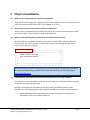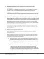
1
Christie Interactivity Kit Technical Frequently Asked Questions (FAQs) This version: March 4, 2014 The latest version of this document is maintained at www.christiedigital.com All brand names and product names are trademarks, registered trademarks or tradenames of their respective holders. Windows is a registered trademark of Microsoft Corporation in the United States and other countries. Mac is a trademark of Apple Inc., registered in the U.S. and other countries. Index 1 2 Tips for a successful install .................................................................................................................... 4 Physical installation............................................................................................................................... 5 2.1 2.2 2.3 2.4 2.5 2.6 2.7 2.8 2.9 2.10 2.11 2.12 2.13 2.14 2.15 2.16 2.17 3 Configuration ...................................................................................................................................... 12 3.1 3.2 3.3 3.4 3.5 3.6 3.7 4 What sizes are supported by the Christie Interactivity Kit? .........................................................................5 How does the Christie Interactivity Kit connect to a computer? .................................................................5 Where are the USB and power connections on the Christie Interactivity Kit? ............................................5 If the computer is not close to the Christie Interactivity Kit, can I use a USB extender? .............................5 What other kinds of displays, besides Christie MicroTiles, will work with the Christie Interactivity Kit?....6 When tiling multiple displays together, how do I adjust for the gaps between displays? ..........................6 What kind of mounting system should be used? .........................................................................................6 Can it be installed so that the front of the frame is flush with the surrounding wall? ................................7 Do I need to install a cosmetic cover over the touch frame? ......................................................................7 Can I use standard Christie MicroTiles feet? ................................................................................................7 Can I retrofit an existing Christie MicroTiles display with the Christie Interactivity Kit? .............................8 Do I need to protect LCD flat panels before using them as a touchscreen? ................................................9 How big a Christie Interactivity Kit is required to fit around my display? ....................................................9 How big a gap will there be between my display and the Christie Interactivity Kit? .................................10 Can the display be rotated – e.g., in portrait – in relation to the Christie Interactivity Kit? ......................10 Can the Christie Interactivity Kit be rotated 90°, or face up in a table? ....................................................11 What kind of multi-touch technology is a good choice for high ambient light indoor environments? .....11 What happens when I connect the Christie Interactivity Kit to a Windows 7/8 computer? .....................12 Do I need to run a special program on the host computer in order to process the touch data? ..............12 Is the Windows 8 operating system supported?........................................................................................12 Does the Christie Interactivity Kit work with Mac® or other operating systems? .....................................12 Do the sensors need to be calibrated or aligned manually? ......................................................................12 Will the Christie Interactivity Kit automatically detect its own size? .........................................................13 How does the touch surface area get mapped to the display when not using Christie MicroTiles? .........13 Touch performance............................................................................................................................. 13 4.1 Do I have to use my finger or a special stylus to register a touch? ............................................................13 4.2 Can I reject unwanted touches? ................................................................................................................13 ™ ™ 4.3 What are the advantages of Baanto ShadowSense technology over alternatives? ...............................13 4.4 How do the resolution and number of supported touches vary with the width of the Christie Interactivity Kit? ......................................................................................................................................................14 4.5 How does average latency change with the size of the Christie Interactivity Kit? ....................................15 4.6 Does touch performance change depending upon the number of simultaneous touches? .....................15 4.7 Will all areas of the touch surface have the same level of performance? .................................................15 5 Working with graphics cards ............................................................................................................... 16 5.1 How do I associate the Christie Interactivity Kit with the entire computer desktop if I have multiple graphic outputs? .....................................................................................................................................................16 5.2 What limitations are there when spanning a desktop across multiple outputs? ......................................17 5.3 How should Christie MicroTiles subarrays be arranged when used with a graphics card that requires identical output resolutions in order to span the desktop? ....................................................................................17 Christie® Interactivity Kit | Technical FAQs | Revised March 4, 2014 ©2012 Christie Digital Systems USA, Inc. Page 2 6 Working with applications .................................................................................................................. 18 6.1 6.2 6.3 6.4 6.5 Why does my application process multi-touch gestures as if they were single clicks on a mouse? ..........18 What gestures are supported natively in Windows 7/8?...........................................................................18 What desktop computing applications already exist with support for multi-touch? ................................18 How do I create a multi-touch application? ...............................................................................................19 What resources are available for programmers? ......................................................................................19 Christie® Interactivity Kit | Technical FAQs | Revised March 4, 2014 ©2012 Christie Digital Systems USA, Inc. Page 3 FAQs 1 Tips for a successful install Please read the full document. But for ease of reference, here are some of the top FAQs: If installing with Christie® MicroTiles®, use the modified feet – do not use the standard feet, they stick out too far in the front and do not provide mounting locations for the Interactivity Kit. These modified feet are available as part of the Christie MicroTiles mounting components for the Christie Interactivity Kit (see question 2.10). If installing with a display other than Christie MicroTiles, make sure your mounting interface provides a flat plane (within 5mm) and allows access to the Interactivity Kit service screws (see question 2.7). If the surrounding wall is flush to the front of the Interactivity Kit frame, leave a small amount of room around the frame (minimum 12.1mm) for assembly and servicing (see question 2.8). If a different color or finish is required, the Interactivity Kit can be covered by a cosmetic skin or fascia, supplied by the customer (see question 2.9). Select the appropriate operating system and application to support the kind of multitouch functionality desired – Windows® 7 is currently the most widely used and tested platform (see questions 3.1 through 3.4). If using a graphics card with multiple outputs, ensure it supports “spanning” the desktop in the desired orientation (i.e., landscape or portrait) – merely extending the desktop won’t work (see question 5.1). If using MicroTiles with multiple ECUs, divide the subarrays evenly – most graphics cards only support “spanning” if each output resolution is the same (see question 5.3). Although multi-touch applications are becoming more common, a custom program may be required to achieve the functionality desired (see question 6.1). For a great touch experience, refer to development guidelines and best practices (see question 6.5), and avoid placing interface components at the very top of the display (see question 4.7). Christie® Interactivity Kit | Technical FAQs | Revised March 4, 2014 ©2012 Christie Digital Systems USA, Inc. Page 4 2 Physical installation 2.1 What sizes are supported by the Christie Interactivity Kit? There are 84 valid configurations, ranging from 3x1 to 16x6 modules in size, or from 4 x 1ft to 21.4 x 6ft. The maximum touch surface area is 267” diagonal, or 12 sq. m. 2.2 How does the Christie Interactivity Kit connect to a computer? Simply connect a USB cable from the master controller on the Christie® Interactivity Kit to a USB port on a computer. The 3x1 base kit includes a 10ft USB cable. 2.3 Where are the USB and power connections on the Christie Interactivity Kit? Both connections are located on the back of the master controller. When looking at the frame from the front, the master controller is the top left assembly, incorporating both the top left corner and the adjacent sensor bar. Master controller is top left when viewed from the front The exact location and clearance dimensions for the USB and power connections are illustrated on the product CAD drawings, available from the Christie Interactivity Kit downloads page at www.christiedigital.com 2.4 If the computer is not close to the Christie Interactivity Kit, can I use a USB extender? Yes. However, it is the responsibility of the customer to make sure a third-party cable will perform as desired in any particular application. Although Christie does not recommend or warrant a specific third-party provider of USB extenders, the following extender has been tested successfully with the Christie Interactivity Kit: ICRON USB Ranger 2101 using a 25ft Ethernet cable. The extender is rated for up to 100m/330ft, but this has not been tested yet. Christie® Interactivity Kit | Technical FAQs | Revised March 4, 2014 ©2012 Christie Digital Systems USA, Inc. Page 5 2.5 What other kinds of displays, besides Christie MicroTiles, will work with the Christie Interactivity Kit? The Interactivity Kit is independent of the type of display, as it connects directly to the source computer via USB. The display could be Christie MicroTiles, LCD flat panel, plasma, rear projection, or another display type. Please note that the display must be flat; the Interactivity Kit cannot be mounted in a curve (see question 2.7 below). 2.6 When tiling multiple displays together, how do I adjust for the gaps between displays? When using MicroTiles, by default the product compensates for the gaps so that images displayed across multiple tiles are not distorted. This can be tweaked if necessary through the MicroTiles UI. When using other display technologies, either the display or the graphics card must have the ability to compensate for any physical bezels or gaps between display surfaces, otherwise images will be distorted and touches will not be mapped correctly. For this reason, it is strongly recommended that displays are spaced apart evenly. Depending upon the display and graphics card being used, it may not be possible to compensate for gaps if they are inconsistent. 2.7 What kind of mounting system should be used? When installed with Christie MicroTiles, please use the MicroTiles mounting components available from Christie. When installed with other displays, such as flat panels or rear projection walls, the customer is responsible to provide a mounting system for the Christie Interactivity Kit. There are two main concerns which should be taken into consideration: 1. If the master controller, corners, and connector pieces are not mounted in a flat plane (within 5mm) and spaced apart correctly, it will not be possible to assemble the sensor bars and light bars to them. Therefore, a flat plane with appropriately spaced mounting locations is critical for a successful install. 2. Each light bar and sensor bar attaches to the connector pieces using four screws on the inside face of the frame. It is recommended that the touch surface is located slightly proud of these screws, in which case a means for accessing these screws must be provided in the event that one of the bars must be removed for servicing. Possible ways to do this include providing sufficient margin around the perimeter of the display to allow access, or providing a means of moving either the frame or the display. Christie® Interactivity Kit | Technical FAQs | Revised March 4, 2014 ©2012 Christie Digital Systems USA, Inc. Page 6 Download CAD drawings providing all the key dimensions and clearance requirements from the Christie Interactivity Kit downloads page at www.christiedigital.com 2.8 Can it be installed so that the front of the frame is flush with the surrounding wall? No, unless the wall incorporates some sort of removable paneling, or unless there is a small gap around the perimeter of the Christie Interactivity Kit frame. This is because in order to remove the light bars and sensor bars, each bar must be rotated outwards after removing the four screws on the internal face. Any object immediately adjacent to the outside of the frame would interfere with this rotation and prevent removal of the bar. The minimum clearance dimension on the outside of the Interactivity Kit frame is 12.1mm, and is illustrated on the CAD drawings for the product. Download CAD drawings from the Christie Interactivity Kit downloads page at www.christiedigital.com 2.9 Do I need to install a cosmetic cover over the touch frame? This depends on the cosmetic requirements of the application. The Christie Interactivity Kit is installed in modular pieces with a professional black finish, but it may be possible to see slight variations between modules depending upon the environment and viewing angle. To achieve a different color or finish, the Interactivity Kit can be covered by a cosmetic skin or fascia, supplied by the customer. Under all circumstances, ensure that the Interactivity Kit is accessible for assembly and servicing. Download CAD drawings providing all the key dimensions and clearance requirements from the Christie Interactivity Kit downloads page at www.christiedigital.com 2.10 Can I use standard Christie MicroTiles feet? No. The standard center and end feet which ship with Christie MicroTiles protrude too far at the front, preventing the Christie Interactivity Kit from being mounted close to the screen surface. Although it is technically feasible to mount the entire frame further forward, this would require custom brackets and would result in touches being registered well in advance of the object touching the screen – therefore, it is not recommended. Christie has designed modified center and end feet which are shorter and which, combined with small L-shaped brackets, provide the appropriate mounting locations along the bottom of the array for the Christie Interactivity Kit. These modified feet are available as part of the MicroTiles mounting components for the Christie Interactivity Kit. Christie® Interactivity Kit | Technical FAQs | Revised March 4, 2014 ©2012 Christie Digital Systems USA, Inc. Page 7 For more information on what parts you need to order, contact Christie directly, or try the free online application MicroTiles Designer at www.christiedigital.com Standard MicroTiles feet 296.82mm depth, interferes with the Interactivity Kit. Comes with MicroTiles 123- part numbers. Modified MicroTiles feet 287.09mm depth, with attachment points for the Interactivity Kit. Packaged with additional interface brackets in Interactivity Kit 108- part numbers. Contact Christie for more details. 2.11 Can I retrofit an existing Christie MicroTiles display with the Christie Interactivity Kit? Yes, but the array must be disassembled in order to attach the modified feet. The modified feet provide sufficient clearance for the Christie Interactivity Kit along the bottom, and combined with Christie® Interactivity Kit | Technical FAQs | Revised March 4, 2014 ©2012 Christie Digital Systems USA, Inc. Page 8 the side and top adapter plates provide mounting locations around the perimeter of the display. For more information on the modified feet, see previous question above. 2.12 Do I need to protect LCD flat panels before using them as a touchscreen? Yes. It is important to protect LCD flat panels, including the Christie FHD551-X, from the potential damage which could be caused by excessive pressure on the face of the screen. This is typically achieved either by using panels which have bonded glass covering the surface area, or by installing a separate protective layer of glass across the front of the entire display. 2.13 How big a Christie Interactivity Kit is required to fit around my display? If the display is Christie MicroTiles, the size of Interactivity Kit will equal the size of the MicroTiles array. For example, a 12x4 Interactivity Kit fits a 12x4 MicroTiles array. If the display is not Christie MicroTiles, you will need to calculate the appropriate size of Interactivity Kit to fit around it, such that the active touch surface area is no smaller than the display. Calculating the active touch surface area is easy. The minimum size of the Christie Interactivity Kit is 3 modules wide by 1 module high, which provides an active touch surface area of 1,224mm wide by 306mm high. Each extra module added to the width makes the touch surface 408mm wider, and each added to the height makes the touch surface 306mm taller. The following table provides the width and height of the touch surface area for each valid number of modules wide and high: Touch surface width Touch surface height Modules mm ft & inches Modules mm ft & inches 3 4 5 6 7 8 9 10 11 12 13 14 15 16 1,224 4' 0.19" 306 1' 0.05" 1,632 5' 4.25" 612 2' 0.09" 2,040 6' 8.32" 918 3' 0.14" 2,448 8' 0.38" 1,224 4' 0.19" 2,856 9' 4.44" 1,530 5' 0.24" 3,264 10' 8.50" 1 2 3 4 5 6 1,836 6' 0.28" 3,672 12' 0.57" 4,080 13' 4.63" 4,488 14' 8.69" 4,896 16' 0.76" 5,304 17' 4.82" 5,712 18' 8.88" 6,120 20' 0.95" 6,528 21' 5.01" Christie® Interactivity Kit | Technical FAQs | Revised March 4, 2014 ©2012 Christie Digital Systems USA, Inc. Page 9 2.14 How big a gap will there be between my display and the Christie Interactivity Kit? If Christie MicroTiles are being used, there will be a nominal 5.4mm gap all the way around the display, between the outside edge of the touch surface area and the inside edge of the Interactivity Kit frame, as illustrated below: 5.4mm 7x4 MicroTiles 7x4 Interactivity Kit touch surface area = 2,856 x 1,224 mm 7x4 MicroTiles display area = 2,856 x 1,224 mm 5.4mm If an alternative display is being used, the size of the gap will vary depending upon the display and configuration. In some cases, the gap may be relatively large, and care should be taken to plan an aesthetic or functional way to hide or integrate the gap into the overall design. An example is provided below: 9.6mm 4x1 FHD551-X flat panels in portrait 7x4 Interactivity Kit touch surface area = 2,856 x 1,224 mm 4x1 portrait FHD551-X display area = 2,745.2 x 1,215.5 mm 60.8mm Note: When the display area is smaller than the active touch surface area, use the masking function built into the Christie Interactivity Kit to ensure touch data are mapped properly to the display. See question 3.7 below for more details. 2.15 Can the display be rotated – e.g., in portrait – in relation to the Christie Interactivity Kit? Yes, however, this makes the integration more complicated, and requires some careful planning on the part of the customer. Potential issues include: Christie® Interactivity Kit | Technical FAQs | Revised March 4, 2014 ©2012 Christie Digital Systems USA, Inc. Page 10 1. Some graphics cards may not allow portrait mode to be selected concurrently with spanning the desktop across multiple outputs. Spanning (not extending) the desktop is required when using the Christie Interactivity Kit with multiple tiled displays (see question 3.1 below for more details). There may be workarounds for graphics cards which have this limitation, but these may require programming or additional hardware, and should be tested by the customer beforehand to make sure the desired setup is achievable. 2. The normal orientation of the Christie Interactivity Kit in relation to the display is such that the sensors are along the top of the display. If the Interactivity Kit and display are not both in their normal orientation, and one is rotated 90°, 180° or 270° from the other, touch events will not be mapped accurately. To correctly map the touch data when installing portrait or rotated displays contact Christie Technical Support for assistance at [email protected]. 2.16 Can the Christie Interactivity Kit be rotated 90°, or face up in a table? In the normal orientation of the product, i.e., upright, the sensors are located along the top of the Christie Interactivity Kit, providing natural shielding from other infrared light sources, such as the sun or overhead lights. This helps to ensure excellent touch performance even in high ambient light environments (see question 2.17 below). Rotating the frame 90°, or installing it face up in a table, may inhibit touch performance by exposing the sensors to excessive ambient light. It is the responsibility of the customer to validate whether or not the touch performance under any other orientation is acceptable in the context of their specific application and lighting environment. 2.17 What kind of multi-touch technology is a good choice for high ambient light indoor environments? The Christie Interactivity Kit is an ideal choice for high ambient light indoor environments. In the normal orientation of the product, i.e., upright, the sensors are located along the top of the Christie Interactivity Kit, providing natural shielding from external infrared light sources. By contrast, some alternative technologies struggle in high ambient light environments, especially those which have sensors located in positions where they are highly exposed to external infrared light sources. For instance, some products use sensors located along both the top and one side of the display, and consequently may not detect touches in well lit spaces. Christie® Interactivity Kit | Technical FAQs | Revised March 4, 2014 ©2012 Christie Digital Systems USA, Inc. Page 11 3 Configuration 3.1 What happens when I connect the Christie Interactivity Kit to a Windows 7/8 computer? The computer will detect the Christie Interactivity Kit as a multi-touch device, in the same way that a USB mouse or keyboard would be detected. This is unlike some other multi-touch products, which require special drivers in order to be recognized by Windows 7/8. 3.2 Do I need to run a special program on the host computer in order to process the touch data? No, the Christie Interactivity Kit computes the touch data internally, so all you need to do is connect the USB cable to a computer that supports the USB-HID 1.1 specification. Some other multi-touch systems – especially those which support a large number of touches – do not compute the touch data internally, and so require an external program running on the host PC at all times. This creates another point of failure, and slows down customer applications running on the PC when multiple touches are being processed in the background. 3.3 Is the Windows 8 operating system supported? Yes. Make sure you are using the latest firmware for the Interactivity Kit. Download firmware (may require login) from the Christie Interactivity Kit downloads page at www.christiedigital.com 3.4 Does the Christie Interactivity Kit work with Mac® or other operating systems? In most cases, the Christie Interactivity Kit will be recognized as a mouse or pointer with Mac or other operating systems that do not support external multi-touch devices natively. For these situations, the Christie Interactivity Kit provides multi-touch data in a custom HID collection, which the developer can utilize when programming their application for any operating system that supports USB HID 1.1. Refer to section 6 Working with applications for more information on application development. 3.5 Do the sensors need to be calibrated or aligned manually? No, the Christie Interactivity Kit has been designed so that the mechanical assembly ensures the sensors are properly aligned with the LEDs, therefore no manual adjustment is required. By contrast, systems that use imaging cameras – either external or at the corners of the display – require extremely precise alignment in order to function properly. Any misalignment introduced through shipping or installation can be troublesome to fix. Christie® Interactivity Kit | Technical FAQs | Revised March 4, 2014 ©2012 Christie Digital Systems USA, Inc. Page 12 3.6 Will the Christie Interactivity Kit automatically detect its own size? Yes, even though the Christie Interactivity Kit can be assembled into 84 different sizes, ranging from 3x1 to 16x6, there is no manual mapping or configuration required. The system will detect its own size upon power up. 3.7 How does the touch surface area get mapped to the display when not using Christie MicroTiles? Unless the display covers the exact same dimensions as a MicroTiles array, it will be smaller than the active touch surface area of the Interactivity Kit. As a result, some portion of the active touch surface area must be masked in order to ensure that the touch points are mapped properly. Refer to question 2.14 above for help on calculating the gap between the display area and the active touch surface area. In addition to this physical gap, include the size of the bezel when calculating the amount of the active touch surface area which must be masked. There is a masking function in the Christie Interactivity Kit configuration software which allows the user to create masked areas at the top, bottom, left or right of the display. These are independent settings – i.e., the size of the masked area on the left does not need to match the size on the right, and so on. For more information on this setting, refer to the User Manual. 4 Touch performance 4.1 Do I have to use my finger or a special stylus to register a touch? No, the Christie Interactivity Kit will recognize any object. 4.2 Can I reject unwanted touches? Yes, the Christie Interactivity Kit includes user-configurable limits for touch size, opacity, and duration to filter out unwanted touch events, such as a person leaning up against the display, or a piece of debris stuck on the display surface. 4.3 What are the advantages of Baanto™ ShadowSense™ technology over alternatives? The Christie Interactivity Kit utilizes Baanto™ ShadowSense™ technology, which solves many of the technical issues that plague other touch technologies. Baanto™ ShadowSense™ employs a unique architecture of proprietary shadow sensors and infrared LEDs to reliably detect multi-touch gestures across practically any surface size. Christie® Interactivity Kit | Technical FAQs | Revised March 4, 2014 ©2012 Christie Digital Systems USA, Inc. Page 13 Sensors along top (shown as green circles) Infrared LEDs along sides and bottom (shown as blue strips) For more information on Baanto™ ShadowSense™ technology, visit www.baanto.com 4.4 How do the resolution and number of supported touches vary with the width of the Christie Interactivity Kit? The Christie Interactivity Kit has been designed so that the number of supported touches is a function of its width, increasing with each sensor bar added, up to a maximum system limit of 18 touches. The number of supported touches at each width has been optimized to suit the number of people that can comfortably draw common gestures on the multi-touch surface at the same time. As each sensor bar is added to the width of the Christie Interactivity Kit, the grid of touch points computed by the system is spread over a larger area, resulting in a gradually coarser touch resolution. This has been optimized so that, even at the maximum size, touch resolution remains very acceptable for typical applications. The following table illustrates the change in the number and resolution of touches from 3 to 16 modules wide: Christie® Interactivity Kit | Technical FAQs | Revised March 4, 2014 ©2012 Christie Digital Systems USA, Inc. Page 14 3 Touches Resolution (mm) 4.5 4 5 6 7 8 9 10 11 12 13 14 15 16 4 6 7 9 10 12 13 15 16 18 18 18 18 18 0.3 0.4 0.5 0.6 0.7 0.8 0.9 1.0 1.1 1.2 1.3 1.4 1.5 1.6 How does average latency change with the size of the Christie Interactivity Kit? As the system grows in size, more sensors are added along the top, and more LEDs along the sides and bottom. As a result, the system must process more data, slightly reducing the speed at which touches are registered. The following table illustrates the change in average latency in milliseconds from a 3x1 to a 16x6 configuration: 1 2 3 4 5 6 4.6 3 4 5 6 7 8 9 10 11 12 13 14 15 16 6 6 7 8 9 9 10 11 11 12 13 13 14 15 7 8 8 9 10 10 11 12 12 13 14 15 15 16 8 9 9 10 11 11 12 13 13 14 15 16 16 17 9 10 10 11 12 12 13 14 15 15 16 17 17 18 10 11 11 12 13 13 14 15 16 16 17 18 18 19 11 12 12 13 14 15 15 16 17 17 18 19 19 20 Does touch performance change depending upon the number of simultaneous touches? Yes, performance will vary slightly depending upon the number and location of touches. For instance, the response time (measured in milliseconds) will be slightly faster for a single touch than for multiple simultaneous touches. This behavior is normal among large format, multi-touch systems, due to the high volume of data which must be processed. To help ensure comparability among technologies, it is standard practice among manufacturers to publish specifications based on single touch performance, unless otherwise stated. 4.7 Will all areas of the touch surface have the same level of performance? All optical based systems will have small areas of the touch surface which are less sensitive than the rest. Often these are located at the most acute angles to the sensors or cameras, where it is difficult to triangulate touch events, or in areas where the infrared light must travel the furthest. In the case of the Interactivity Kit, this means that touch performance will be less sensitive at the very top of the display, and at the center-top in very large configurations. This should be taken into consideration when designing the user experience and layout of the touch interface for a particular application. Christie® Interactivity Kit | Technical FAQs | Revised March 4, 2014 ©2012 Christie Digital Systems USA, Inc. Page 15 5 Working with graphics cards Please note that the Interactivity Kit may be used with a wide variety of graphics cards and many different applications. The functionality of these cards is outside of Christie’s control. The following section provides some general guidance on the topic, and it is the responsibility of the customer to ensure a suitable graphics card is chosen for any particular application. 5.1 How do I associate the Christie Interactivity Kit with the entire computer desktop if I have multiple graphic outputs? When using the Christie Interactivity Kit with a computer that has more than one graphic output, the graphics card must support desktop “spanning”, otherwise the Christie Interactivity Kit will be associated with the primary output only. Many graphics cards do not allow spanning of a desktop across multiple outputs. “Spanning” is when the desktop start menu or dock, as well as full screen applications, span across all the display outputs. This is different to an “extended” desktop, where the desktop start menu or dock remains associated with the primary display only. For more information on the limitations of graphics cards when spanning desktops, see question 5.2 below. The following diagrams illustrate the difference between extended and spanned desktops. 6x4 MicroTiles divided into two 3x4 subarrays Example 1: Extended desktop As shown, the start menu or dock only appears on the primary output when the desktop is extended. Touch data will be associated with the primary output only. As a result, touch data will not be mapped correctly with this setup. Touch data via USB When using multiple outputs, it is critical that the graphics card supports true spanning of the desktop (see Example 2 below). Christie® Interactivity Kit | Technical FAQs | Revised March 4, 2014 ©2012 Christie Digital Systems USA, Inc. Subarray 1 Subarray 2 Start menu / dock Output 1 (primary) Output 2 Compute r Page 16 6x4 MicroTiles divided into two 3x4 subarrays Example 2: Spanned desktop As shown, the start menu or dock spans across both outputs when the desktop is spanned. Touch data will be associated with the entire desktop because it is spanning both outputs. As a result, touch data will be mapped correctly with this setup. Touch data via USB Subarray 1 Subarray 2 Start menu / dock Output 1 Output 2 Compute r 5.2 What limitations are there when spanning a desktop across multiple outputs? Spanning (not extending) the desktop is required when using the Interactivity Kit with a computer that has multiple outputs (see previous question). However, graphics cards can impose restrictions when spanning the desktop. For instance, Nvidia’s Mosaic Mode, which supports desktop spanning and is available on certain Nvidia graphics cards, has limitations such as (at the time of writing): 1. Spanning is allowed only in landscape mode. If the display outputs are in portrait mode, there is no utility to enable Mosaic Mode at the same time. There are workarounds for this limitation of Mosaic Mode, but these may require programming or additional hardware, and should be tested by the customer beforehand to make sure the desired setup is achievable. 2. Spanning is allowed only if the resolution of each output is identical. When used with Christie MicroTiles, this means each ECU subarray must be the same resolution (see next question below). 5.3 How should Christie MicroTiles subarrays be arranged when used with a graphics card that requires identical output resolutions in order to span the desktop? MicroTiles are very flexible. However, if the graphics card requires each output to be the same resolution in order to enable spanning the desktop (see previous question above), this will constrain what MicroTiles subarray layouts are possible. For example, if the canvas size is 11x5 MicroTiles, because both 11 and 5 are prime numbers, it is impossible to divide the canvas evenly into multiple subarrays. As a result, depending upon the limitations of the graphics card, only one ECU may be used, constraining the resolution of the Christie® Interactivity Kit | Technical FAQs | Revised March 4, 2014 ©2012 Christie Digital Systems USA, Inc. Page 17 canvas to 1.7mm. By contrast, if the size of the display is bumped up to 12x5, there are several ways this configuration could be subdivided evenly (two 6x5s, three 4x5s, four 3x5s, six 2x5s), providing a range of resolution options for the customer. The MicroTiles Designer program, available from www.christiedigital.com, will help you configure the right number of subarrays when combining the Interactivity Kit with Christie MicroTiles. 6 Working with applications 6.1 Why does my application process multi-touch gestures as if they were single clicks on a mouse? The performance of an application with the Christie Interactivity Kit will depend upon whether or not that application supports multi-touch gestures. For instance, if an application has been designed for single clicks on a mouse, any more complex gestures or multi-touch actions performed on the Christie Interactivity Kit will be processed by that application as if they were single clicks on a mouse. However, if an application has been designed to accept multi-touch gestures, such as pinching or flicking, then these actions performed on the Christie Interactivity Kit will be processed as such. 6.2 What gestures are supported natively in Windows 7/8? Supported gestures include panning, zooming, rotating, flicking, pressing and tapping. For more information, refer to the Microsoft Windows website, including the following video: http://windows.microsoft.com/en-US/windows7/help/videos/using-windows-touch. 6.3 What desktop computing applications already exist with support for multi-touch? At the moment, the list is relatively short. However, as multi-touch becomes more popular, and is fully embraced in Windows 8, an increasing number of applications for desktop computing will support multi-touch gestures. Some browsers support multi-touch in Windows 7, such as Internet Explorer 8+ and Mozilla Firefox 4+. You can also download the Microsoft Touch Pack for Windows 7, a collection of six games and applications which support multi-touch gestures. Search online, or try the following link: http://www.microsoft.com/en-us/download/details.aspx?id=17368. Please note that Christie does not promote, warrant or support any third party applications. Christie® Interactivity Kit | Technical FAQs | Revised March 4, 2014 ©2012 Christie Digital Systems USA, Inc. Page 18 6.4 How do I create a multi-touch application? To take full advantage of the Christie Interactivity Kit typically requires a custom application, such as a Flash or Silverlight application, that has been programmed to accept multi-touch gestures and will work with whatever operating system it is designed for, such as Windows or Mac. Further information for application developers regarding the touch data provided by the Christie Interactivity Kit is published in the product User Manual. 6.5 What resources are available for programmers? There are many resources and articles online which provide guidance on how to program multitouch applications, and best practices for multi-touch user interface design, including: Learn about Windows 7: Touch http://msdn.microsoft.com/en-us/windows/ee633448.aspx Windows 7 Touch Application Development Guidance http://archive.msdn.microsoft.com/wintouchguide Touch: All Microsoft® Windows applications should have a great touch experience. And doing so is easier than you think. http://msdn.microsoft.com/en-us/library/windows/desktop/cc872774.aspx Multitouch and gesture support on the Flash Platform http://www.adobe.com/devnet/flash/articles/multitouch_gestures.html Christie® Interactivity Kit | Technical FAQs | Revised March 4, 2014 ©2012 Christie Digital Systems USA, Inc. Page 19