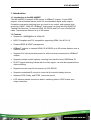
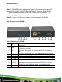
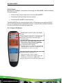
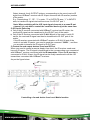
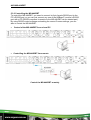
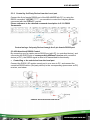
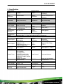
1
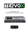
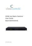
AVG-MS-44HDBT
Features
The MS-44HDBT includes 4 HDMI inputs, 4
HDBaseT outputs, 2 local HDMI outputs, 4 deembedded stereo audio & 4 de-embedded digital
audio outputs.
Support for 1080P@60Hz &
1080p 3D.
HDCP Compliant and DVI
compatible, supporting HDMI
1.4a & DVI1.0.
Powerful EDID & HDCP
management.
HDBaseT outputs, to transmit
HDMI, IR & RS232 up to 60
meters distance over a Cat5E/6
cable.
Supports PoC which provides
power for all the receivers
connected to the HDBaseT
outputs.
Supports multiple control options,
including front panel buttons,
RS232 and IR.
AVG-MS-44HDBT
PLEASE READ THIS PRODUCT MANUAL CAREFULLY
BEFORE USING THIS PRODUCT.
This manual is only for operation instruction only, and
not to be used in a maintenance capacity. The
functions described in this version are current till
March 2015. Any changes of functions and
operational parameters will be updated in future
manual versions. Please refer to your dealer for the
latest product details.
Version 1.0 1/3/15
AVG-MS-44HDBT
SAFETY OPERATION GUIDE
In order to guarantee the reliable operation of the equipment and safety of the
user, please abide by the following procedures in installation, use and
maintenance:
1. The system must be earthed properly. Please do not use two blade plugs
and ensure the alternating power supply ranges from 100v to 240v and from
50Hz to 60Hz.
2. Do not install the switcher in an environment where it will be exposed to hot
or cold temperatures.
3. This unit will generate heat during operation, please ensure that you allow
adequate ventilation to ensure reliable operation.
4. Please disconnect the unit from mains power if it will be left unused for a
long time.
5. Please DO NOT try to open the casing of the equipment, DO NOT attempt to
repair the unit. Opening the unit will void the warranty. There are high
voltage components in the unit and attempting to repair the unit could result
in serious injury.
6. Do not allow the unit to come into contact with any liquid as that could result
in personal injury and product failure.
AVG-MS-44HDBT
TABLE OF CONTENTS
Introduction .............................................................................................................. 1
About the MS-44HDBT ................................................................................. 1.1
Features ....................................................................................................... 1.2
What’s in the Box ..................................................................................................... 2
Product Appearance ................................................................................................ 3
Front View of MS-44HDBT ........................................................................... 3.1
Rear View of MS-44HDBT ............................................................................ 3.2
Connection with RS232 Communication Port ............................................... 3.3
Twisted Pair Cable Connection .................................................................... 3.4
System Connection .................................................................................................. 4
Usage Precautions ....................................................................................... 4.1
System Diagram ........................................................................................... 4.2
Connection Procedure .................................................................................. 4.3
Connection with AVG-HD300R..................................................................... 4.4
Appearance of AVG-HD300R ......................................................... 4.4.1
POC Solution .................................................................................. 4.4.2
Application .................................................................................................... 4.5
System Operations................................................................................................... 5
Button Control............................................................................................... 5.1
IR Control ..................................................................................................... 5.2
Usage of IR Remote ....................................................................... 5.2.1
IR Operations.................................................................................. 5.2.2
RS232 Control .............................................................................................. 5.3
RS232 Commands ......................................................................... 5.3.1
Controlling the MS-44HDBT ........................................................... 5.3.2
AVG-MS-44HDBT
Control of 3rd Party Devices Locally ................................................ 5.3.3
Bi-Directional RS232 Control .......................................................... 5.3.4
USB Firmware Updating ............................................................................... 5.4
Specification ............................................................................................................. 6
Panel Drawing .......................................................................................................... 7
Troubleshooting & Maintenance ............................................................................. 8
AVG-MS-44HDBT
1. Introduction
1.1 Introduction to the MS-44HDBT
The MS-44HDBT includes 4 HDMI inputs, 4 HDBaseT outputs, 2 local HDMI
outputs, 4 de-embedded stereo audio & 4 de-embedded digital audio outputs.
It enables cross-point switching from any input to any output, and supports high
resolution 1080P, 1080p 3D. HDBaseT output ports can work with the HDMI PoC
Twisted Pair Receiver, to transmit HDMI, IR, RS232 and PoC over a Cat5e/Cat6
cable. Transmission distance is up to 60 meters.
1.2 Features
Support for 1080P@60Hz & 1080p 3D.
HDCP Compliant and DVI compatible, supporting HDMI 1.4a & DVI1.0.
Powerful EDID & HDCP management.
HDBaseT outputs, to transmit HDMI, IR & RS232 up to 60 meters distance over a
Cat5E/6 cable.
Supports PoC which provides power for all the receivers connected to HDBaseT
outputs.
Supports multiple control options, including front panel buttons, RS232and IR.
IR OUT signal switching follows with the video signal, can also be separated from
video switching.
Supports remote control from receiver by IR & RS232.
Supports centralized IR control to control all the remote display devices.
Supports PCM, Dolby, and DTS5.1 surround sound.
LCD indicator shows connection status, switching status, HDCP status, and
output resolution.
AVG-MS-44HDBT
2. What’s in the Box
1 x MS-44HDBT
2 x Mounting ears
10 x Screws
1 x RS232 cable
4 x IR converting cables (12V)
8 x Pluggable Terminal Blocks
4 x Plastic cushions
1 x IR remote
1 x Power adapter (DC 48V)
1 x Power cord
1 x User manual
Note: Please confirm that the product and accessories are all included, if not please
contact your dealer.
AVG-MS-44HDBT
3. Product Appearance
3.1 Front Panel
No.
①
②
③
④
Name
Firmware
Power
Indicator
IR Receiver
LCD Screen
⑤
INPUTS/
Menu buttons
⑥
Function
buttons
⑦
OUTPUTS
Description
Micro USB port for firmware update.
Illuminates red when power on.
In-built IR sensor, receive control signal from IR remote.
Shows real-time system status.
Normal mode: Input buttons, ranging from "1" to "4".
Inquiry mode: Press “AV” and hold for more than 3 seconds to
enter this mode. Dial
to change menus,
to change
different channels.
AV synchronous button: To transfer AV and IR signal (from IR
OUT port) synchronously by the switcher.
Note: The 4 IR OUT ports correspond with the 4 HDMI INPUT
ports separately.
Example: To transfer both AV and IR signals from Input 1 to
Output 3.
Operation: Press buttons in this order “Input 1”, “AV”, “Output 3”.
ALL outputs button: To transfer one input to all outputs.
Example: To transfer both AV and IR signals from Input 1 to all
output channels.
Operation: Press buttons in this order “Input 1”, “ALL”.
EDID management button: manually capture and learn the EDID
data from output device.
Example: Input 2 captures and learns the EDID data from Output
4.
Operation: Press buttons in this order “EDID”, “Input 2”, “Output
4”.
Output buttons, ranging from "1" to "4", correspond to the 4
HDBaseT outputs ports.
With the front control panel, the switcher can be controlled directly by pressing the
buttons in this order: “Input Channel” + “AV” + “Output Channel”
“Input Channel”: Select the number of input channel to be controlled.
“Output Channel”: Select the the number of output channel to be controlled.
AVG-MS-44HDBT
3.2 Rear Panel
No.
Name
Description
①
IR ALL IN
IR control signal input port, connect with IR receiver, pass
through to all the HDBaseT ports to control remote devices.
②
HDMI
INPUTS
HDMI input ports, 4 in total, type A female HDMI connector,
connect with HDMI input source devices.
IR OUT
Connect with IR transmitter, to emit the IR signal sent from the
HDBaseT ports of the far-end Receiver. These IR OUTs make
up an IR matrix with the IR INs on the HDBaseT receivers, and
all IR signals can be switched synchronously with the AV
signal, or separately switched.
③
IR IN: Connect with IR receiver, fixed IR input for the output,
cannot be switched separately. It makes up an IR bi-directional
transmission with the IR OUT on the corresponding HDBaseT
receiver.
④
HDMI: HDMI output port, connect with HDMI displayers,
OUTPUTS deliver same input signals with HDBaseT ports, split HDMI
output for local monitoring.
COAX: HDMI de-embedded digital audio output.
HDBaseT: Works with HDBaseT receivers, such as the HDMI
twisted pair receiver & HDMI PoC twisted pair receiver. It can
extend AV, IR and RS232 signal to 60m distance. Meanwhile, it
AVG-MS-44HDBT
can provide power for the receivers which support PoC.
RS232: Serial port to communicate with the RS232 port on
corresponding HDBaseT receiver. When controlled by
HDBaseT receiver, the communication protocol must be the
same with the MS-44HDBT.
AUDIO: HDMI de-embedded stereo audio output
⑤
RS232
Serial port for unit control, 9-pin female connector, connects
with control device such as a PC.
⑥
Power
Indicator
Illuminates red when powered on.
⑦
48V DC
Connect with 48V DC power adaptor.
⑧
GROUND
Connect to grounding, make the unit ground well.
⑨
TCP/IP
TCP/IP port for unit control, optional function.
⑩
IR EYE
Connect with extended IR receiver, use the IR remote to control
the MS-44HDBT.
3.3 Connection with RS232 Communication Port
The MS-44HDBT can be controlled by a 3rd Party control system through the
RS232 communication port. This RS232 communication port is a female 9-pin D
connector. The definition of its pins is listed in the table below.
F5-1. 9HDF
No.
1
2
3
4
5
6
7
8
9
Pin
N/C
Tx
Rx
N/C
Gnd
N/C
N/C
N/C
N/C
Function
Unused
Transmit
Receive
Unused
Ground
Unused
Unused
Unused
Unused
AVG-MS-44HDBT
3.4 Twisted Pair Cable Connection
The cables for HDBaseT ports must be straight-through ones, using T568A or T568B
standard. The connectors can be T568A or T568B, but both sides must be the same.
TIA/EIA T568A
TIA/EIA T568B
Pin
Cable color
Pin
1
green white
1
orange white
2
green
2
orange
3
orange white
3
green white
4
blue
4
blue
5
blue white
5
blue white
6
orange
6
green
7
brown white
7
brown white
8
brown
8
brown
1st Ground
4--5
1st Ground
Cable color
4--5
2nd Ground 3--6
2nd Ground 1--2
3rd Group
1--2
3rd Group
3--6
4th Group
7--8
4th Group
7--8
4. System Connection
4.1 Usage Precautions
1. System should be installed in a clean environment with temperature and humidity
maintained to within equipment specification.
2. All of the power switches, plugs, sockets and power cords should be insulated and
safe.
3. All devices should be connected before power on.
AVG-MS-44HDBT
4.2 System Diagram
4.3 Connection Procedure
Step 1. Connect HDMI source devices (e.g. DVD) to HDMI input ports of the AVGMHD44TP with HDMI cables.
Step 2. Connect HDMI displays (e.g. HDTV) to HDMI output ports of the MS44HDBT with HDMI cables.
Step 3. Connect speakers/ headphones to AUDIO output ports (3-pin captive screw
connectors).
Step 4. Connect the HDBaseT ports of HDBaseT receiver and the MS-44HDBT with
twisted pair cable
Step 5. Connect the RS232 port (9 pin female D) of the MS-44HDBT with control
device (e.g. PC).
Step 6. Connect the RS232 port of the device to be controlled to the RS232 port of
the HDBaseT Receiver or MS-44HDBT. The control signal can be
transmitted bi-directionally.
AVG-MS-44HDBT
Step 7. MS-44HDBT can be controlled by its built-in IR receiver or the external IR
receiver connected to the IR EYE port. IR signals can be transmitted bi-directionally
between MS-44HDBT’s IR OUT/ IR IN and HDBaseT Receiver’s IR IN / IR OUT.
In this mode, we can control MS-44HDBT remotely with the MHD44TP’s IR
Remote.
Note: The IR IN port has built-in infrared carrier receiver.
Step 8. Connect a DC48V power adaptor to the power port of MS-44HDBT.
4.4 Connection with HD300R
MS-44HDBT can work with HD300R to extend transmission distance up to 70m.
4.4.1 Appearance of HD300R
No.
Name
①
ON
②
LINK
③
OUT
④
Power
⑤
HDBT IN
⑥
HDMI OUT
⑦
IR IN
⑧
IR OUT
⑨
RS232
⑩
DC 24V
Description
Working status indicator, blinks green to indicate device processor is
operational.
Twisted Pair link status indicator, illuminates green when the
connection is successful.
Output indicator, when the connected display works normally, it will
illuminate: stays on when the display supports HDCP and blinks if
not.
Illuminates when power on
Connects with the HDBT OUT port of MS-44HDBT by using a single
CAT5e/6 cable (60m length in max).
HDMI output port, connect with HDMI display.
Connect with the IR receiver, the IR signal received from this port is
available on the MS-44HDBT rear panel.
Connect with an IR Emitter to control end device.
Serial port, connects with the control terminal to control the
controlled terminal, supports bi-directional RS232 control between
MS-44HDBTand HD300R.
Connect with a DC 24V power adapter. (Not necessary when
connecting with MS-44HDBT)
AVG-MS-44HDBT
4.4.2 PoC Solution
For convenience, both the MS-44HDBT & HD300R support PoC this eliminates the
need for a power supply for the HD300R. Connect the MS-44HDBT & HD300R as
per the figure below:
4.5 Application
The MS-44HDBT’s performance and transmission distance makes it perfect for use
in the computer realm, security monitoring, big screen displays, conference system,
television, education and banking institutions etc.
5. System Operations
5.1 Button Control
The operation examples are showed in 3.1 Front Panel. Here we make a brief
introduction to the system inquiry operations.
Press and hold the button “AV” for 3 seconds, it will enter into the system inquiry
menu. Use the Left and Right direction buttons to check the previous/next item.
Function Items
Check the
connection status
of inputs
Check the
connection status
of outputs
Correspondence
between inputs
and outputs
Example
Out
1 2 3 4
Connect Y Y N N
Description
Y means the corresponding port is
connected with input device, N
means not.
Y means the corresponding port is
connected with output device, N
means not.
Out
Input
1 2 3 4
1 2 3 3
Shows the correspondence
between the 4 inputs and 4 outputs.
Check if the input
is with HDCP
In
HDCP
1 2 3 4
Y Y Y N
Y means the input signal is with
HDCP, N means not.
Check if the output
is with HDCP
Out
HDCP
1 2 3 4
Y Y Y N
Y means the output signal is with
HDCP, N means not.
Check the output
resolution
Resolution
Out 1
1920x1080
In
1 2 3 4
Connect Y Y Y Y
Use the UP and DOWN direction
button to check all the 4 output
resolutions.
AVG-MS-44HDBT
5.2 IR Control
By using IR & HDBaseT transmission technology, the MS-44HDBT has the following
IR control options.
Control of the far-end output device from the MS-44HDBT.
Control the local input/output device remotely.
Control the MS-44HDBT locally/remotely.
The MS-44HDBTcan be controlled by its built-in IR receiver or through the IR EYE
port by connecting with an extended IR receiver. It can also be controlled remotely
by a far-end IR device through the twisted pair.
5.2.1 Usage of IR Remote
Standby button, press it to enter / exit standby
mode.
Input channels, range from 1~4, IR signals are
switched synchronously with HDMI signal
correspondingly.
Menu buttons, button AV and ALL have the
same function as the front panel. THROUGH:
To transfer the signals directly to the
corresponding output channels
Example: Press “3”, “THROUGH”, the result will
be IN 3OUT 3. Press “ALL”, “THROUGH”, the
result will be: 11, 22, 33, 44
Output channels, range from 1~4.
Each channel has 1 IR IN, 1 COAX, 1
HDBaseT, 1 RS232, and 1 AUDIO output, and
channel No.1 & No.2 has 1 HDMI output.
AVG-MS-44HDBT
5.2.2 IR Operations
1) IR Matrix Switching
The 4 “IR OUT” ports make up a 4x4 IR matrix with the “IR IN” ports of the far-end
receivers. See as below:
Control of Local Devices or the MS-44HDBT Remotely
The IR signal is received from a corresponding IR remote, then transferred to the
HDBaseT receiver, then to corresponding zone of the matrix through the twisted pair
and finally transferred to the IR OUT port and received by the controlled device.
Switching Operation:
a) Sending command (reference to 5.3 RS232 Control): [x1]R[x2].
x1: Corresponding to the 4 IR OUT ports of the matrix, The IR transmitter
connected to this port can be placed at the IR receiving area of the output
device or the matrix itself.
x2: Corresponding to the zone number (IR signal transmit to the HDBaseT receiver
and then gets to the HDBaseT port of this zone via the twisted pair)
E.g.: Command “3R2.” means to transfer IR signal received from zone 2 to IR
OUT port 3.
b) Using the IR remote: Input channelbutton IROutput channel
Input channel: the 4 INPUT buttons, corresponding to the 4 IR OUT ports of the
matrix.
AVG-MS-44HDBT
Output channel: the 4 OUTPUT buttons, corresponding to the zone (receive IR
signal from HDBaseT receiver with IR IN port connects with IR receiver) number
of the matrix.
E.g.: Press buttons “3”, “IR”, “1” in order, “3” in OUTPUTS area, “1” in INPUTS
area, to transfer IR signal received from zone 3 to IR OUT port 1.
Note: When switching all the 4 IR input signal channels to a same IR out
channel, it is not able to control the controlled device(s) at the same time.
2) IR Carrier Enforcing
Only if the IR receiver connected with HDBaseT receiver has IR carrier, the
received IR signal can be transferred to the IR OUT port of the matrix.
b) Only if the IR receiver connected with IR ALL IN port of the matrix is with IR
carrier, the received IR signal can then be transferred to IR OUT port of the
matrix.
If the IR receiver connected with HDBaseT receiver or IR ALL IN port of the
matrix is not with IR carrier, you need to send the command “%0901.”, and then
you are able to transfer the IR signal to IR OUT port.
3) Control far-end output devices from local IR Port
When you need to control a remote display from local, the IR receiver used must
have an IR carrier. The IR signal is transferred to the corresponding zone connected
with HDBaseT receiver connected with the IR transmitter. When the IR receiver is
connected to IR ALL IN port, the IR signal can be finally transferred to all the 4 IR
transmitters connected with HDBaseT receivers.
As per the figure below:
a)
Controlling a far-end device from Local Matrix location
AVG-MS-44HDBT
1) Controlling far-end devices through the IR ALL IN port
The IR signal received from the IR ALL IN port will be transmitted to all the four farend HDBaseT receivers connected to HDBaseT ports of the MS-44HDBT. See as
per figure below:
Controlling far-end devices through the IR ALL IN port
2) Controlling a local device from far end remote
A user can control local devices such as DVD, matrix etc. remotely. When using, the
IR signal received from the HDBaseT receiver it will be transmitted to the
corresponding IR OUT port of the MS-44HDBT. See below:
Control of local device from remote
3) Controlled by a Third-party IR Control Device
Use the included IR converting cable (see as below), connect the 3-pin end to the IR
input port of the MS-44HDBT, the 2-pin end to the IR output port of the third-party
control device. The IR signal is able to be transmitted via the twisted pair, and finally
gets to the remote output device.
AVG-MS-44HDBT
5.3 RS232 Control
5.3.1 RS232 Commands
Through the RS232 communication port, a user can control a far-end device whose
baud rate is 2400, 4800, 9600, 19200, 38400, 57600 or 115200. Default setting of
the MS-44HDBT: baud rate is 9600, data bit is 8, stop bit is 1 and parity bit is none.
Communication protocol: RS232 Communication Protocol
Baud rate: 9600
Command
Types
Data bit: 8
Command Codes
/*Type;
/%Lock;
/%Unlock;
/^Version;
System
Command
/:MessageOff;
/:MessageOn;
Demo.
Undo.
[x]All.
All#.
All$.
[x]#.
Operation
Command
[x]$.
[x]@.
All@.
[x1] V[x2].
[x1] B[x2].
Status.
Save[X].
Recall[Y].
Clear[Y].
PWON.
Stop bit: 1
Parity bit: none
Functions
Inquire the models information.
Lock the front panel buttons on the Matrix.
Unlock the front panel buttons on the Matrix.
Inquire the version of firmware
Turn off the feedback command from the com port. It will
only show the “Switch Ok”.
Turn on the feedback command from the com port.
Switch to the “demo” mode, 1->1, 2->2, 3->3 … and so
on .The switching interval is 2 seconds.
To cancel the previous operation.
Transfer signals from the input channel [x] to all output
channels
Transfer all input signals to the corresponding output
channels respectively.
Switch off all the output channels.
Transfer signals from the input channel [x] to the output
channel [x].
Switch off the output channel [x].
Switch on the output channel [x].
Switch on all output channels.
Transfer the AV signal from the input channel [x1] to the
output channel [x2].
Transfer the AV and IR signal from the input channel
[x1] to the output channel [x2].
Inquire the input channel to the output channels one by
one.
Save the present operation to the preset command [X],
ranges from 0 to 9.
Recall the preset command [Y].
Clear the preset command [Y].
Work in normal mode.
AVG-MS-44HDBT
PWOFF.
STANDBY.
/%[Y]/[X]:[Z].
[x1] R[x2].
DigitAudioON[x].
DigitAudioOFF[x].
Enter into standby mode and cut off the power supply to
HDBaseT receivers.
Enter into standby mode.
HDCP management command. [Y] is for input (value: I)
or output (value: O). [X] is the number of one port, if the
value of X is ALL, it means all ports. [Z] is for working
status (value: 1 or 0).
Y=I & Z=1, means the input port is compliant with
HDCP.
Y=O & Z=1, means output with HDCP.
Y=I & Z=0, means the input port is not compliant with
HDCP.
Y=O & Z=0, means output without HDCP.
Transfer the IR signal from the input channel [x1] to the
output channel [x2].
Enable HDMI audio output of port x.
X=1, 2, 3, 4, enable this one port.
X=5, enable all the 4 ports.
Disable HDMI audio output of port x.
X=1, 2, 3, 4, disable this one port.
X=5, disable all the 4 ports.
AVG-MS-44HDBT
/+[Y]/[X]:******.
EDIDH[x]B[y].
EDIDPCM[x].
EDIDG[x].
EDIDMInit.
EDIDM[X]B[Y].
EDIDUpgrade[x].
Set communication between PC and HDBaseT receiver.
Y is for RS232 port (connect with RS232 port of
HDBaseT receiver)
Value = 1,2,3,4,5,A,B,C,D,E,F,G or H
The value of Y is defined into the following
meanings (in a given baud rate depended by the
value of X):
a. Y = 1, 2, 3 or 4, send this command to the
corresponding HDBaseT receiver to control far-end
device.
b. Y = 5, send this command to all HDBaseT receivers
to control all far-end devices.
c. Y = A, B, C or D
d. Y = E, F, G or H
For items c or d, send this command, it will be
saved to the matrix switcher but taken without
action to corresponding HDBaseT receiver. And its
command function will be effective almost at the
same time when you send the command PWON
(for item c) or PWOFF (for item d).
Note:
A & E are for port 1.
B & F are for port 2.
C & G are for port 3.
D & H are for port 4.
X is for bound rate (Value ranges from 1 to 7, 1 is for
2400, 2 for 4800, 3 for 9600, 4 for 19200, 5 for
38400, 6 for 57600 and 7 for 115200)
***** is for data (max 48 Byte)
The symbol “.” is the end of one command. If there
are some symbols of “.” in one command, this case
is allowed and the last one is the end.
Copy the EDID from output port [x] to input port [y].
If the EDID data is effective and the audio part supports
not only PCM mode, then force-set it to PCM mode. If
the EDID data is not effective, then set it as initialized
EDID data.
Set the audio part of input port [x] to PCM format in
EDID database.
Get EDID data from the output and display the output
port number of X.
Recover the factory default EDID data.
Manually EDID switching. Copy the EDID data of
output[X] to the input[Y].
Upgrade EDID data via the RS232 port
[X] is for input port, when the value of X is 5, it means to
upgrade to all input ports. When the switcher gets the
command, it will show a message to send EDID file (.bin
file). Operations will be canceled after 10 seconds.
(Note 1) Please cut off all connections of HDBaseT
ports.
AVG-MS-44HDBT
UpgradeIntEDID[x].
EDID/[x]/[y].
%0801.
%0900.
%0901.
%0911.
%9951.
%9952.
%9953.
%9954.
%9955.
%9956.
%9957.
%9958.
%9961.
%9962.
%9963.
%9964.
%9971.
%9972.
%9973.
%9974.
%9975.
%9976.
%9977.
%9978.
Select one type of EDID data and upgrade built-in EDID
data. Supports 4 types of EDID data:
1. 1080P, 2D, PCM2.0
2. 1080P, 2D, 5.1 (audio)
3. 1080P, 3D, PCM2.0
4. 1080P, 3D, 5.1 (audio)
[x] = 1, 2, 3 or 4
When the switcher gets the command, it will show a
message to send EDID file (.bin file). Operations will be
canceled after 10 seconds.
Set the built-in EDID data of input port [x] to type [y].
The value of [y] is 1, 2, 3, and 4. The EDID data types
are same as mentioned above.
Automatically HDCP management. Input is with HDCP,
so is output.
Set as infrared carrier following mode.
Set as infrared carrier enforcing mode.
Reset to factory default.
Check the command sent by port 1 when PWON.
Check the command sent by port 2 when PWON.
Check the command sent by port 3 when PWON.
Check the command sent by port 4 when PWON.
Check the command sent by port 1 when PWOFF.
Check the command sent by port 2 when PWOFF.
Check the command sent by port 3 when PWOFF.
Check the command sent by port 4 when PWOFF.
Check the system locking status.
Check the status while in standby mode.
Check the working mode of infrared carrier.
Check the IP address (only for the PCB with GUI).
Check the connection status of the inputs.
Check the connection status of the outputs.
Check the HDCP status of the inputs.
Check the HDCP status of the outputs.
Check the switching status.
Check the output resolution.
Check the status of digital audio of output channels.
Check the HDCP status of the input ports.
Note:
1) Please disconnect all the twisted pairs before sending command
EDIDUpgrade[X].
2) In above commands, “[”and “]” are symbols for easy reading and do not need to
be typed in actual operation.
3) Please remember to end the commands with the ending symbols “.” and “;”.
4) Type the command carefully, it is case-sensitive.
AVG-MS-44HDBT
5.3.2 Controlling the MS-44HDBT
To control the MS-44HDBT, you need to connect its 9 pin female RS232 port to the
PC’s RS232 port, or you can just connect any one of the HDBaseT receiver’s RS232
port with a PC (RS232 command transmits to the MS-44HDBT via the twisted pair).
By using RS232 control software and setting the correct Comms settings, you are
able to control the MS-44HDBT.
Control of the MS-44HDBT from a local PC
Controlling the MS-44HDBT from remote
Control the MS-44HDBT remotely
AVG-MS-44HDBT
5.3.3 Control by 3rd-Party Device from the Local port
Connect the 9 pin female RS232 port of the MS-44HDBTwith PC, by using the
RS232 command “/+[Y]/[X]:******.”, you are able to control the 3rd-party device
connected with the HDBaseT receiver.
Please reference to the detailed command description in 5.3.1 RS232
Commands.
Control using a 3rd-party Device through the 9 pin female RS232 port
5.3.4 Bi-directional RS232 Control
By connecting one 3p captive screw RS232 port with PC (or controlled device), and
connecting the RS232 port of corresponding HDBaseT receiver with controlled
device (or PC), the RS232 signal is able to be transmitted bi-directionally.
Controlling a far-end device from the local port
Connect the RS232 (3P captive screw) port in one zone to PC, and connect the
controlled RS232 device (3rd party device) to the corresponding (same zone as PC)
receiver, see below:
Control far-end device from local
AVG-MS-44HDBT
Control of the MS-44HDBT from remote receiver
Connect the RS232 (3p captive screw) port in one zone to controlled device (3rd
party device), and connect PC to the corresponding (same zone as controlled
device) receiver, see below:
Control the MS-44HDBT from remote receiver
5.4 USB Firmware Updating
To meet the needs of different users or further addition functions, the firmware of the
device can be upgraded via USB. When you need to upgrade it, please download
the latest upgrade file and then can upgrade it through the update .exe file. Copy the
.exe file to the controller PC and double chick the program to upgrade the firmware.
When the program is running normally, it will enter into the interface (as shown in the
next figure), please press the button
downloaded, and then press the button
and choose the upgrade file
. It is ready to upgrade.
When the update is done, it will appear with a window showing the message Update
success.
Note: The COM number connected with the PC is available from 1 to 9.
AVG-MS-44HDBT
6. Specification
Video Input
Video Output
Input
4 HDMI
Output
Input
Connector
Female HDMI
Output
Connector
Input Level
Input
Impedance
Video General
Gain
T.M.D.S. 2.9V~3.3V
100Ω (Differential)
0 dB
Video Signal
HDMI (or DVI-D)
Resolution
Range
Up to 1920 x 1200@60Hz
or 1080P@60Hz
Transmission
Distance
60m with PoC
Output Level
Output
Impedance
Bandwidth
Maximum Pixel
Clock
Switching
Speed
HDBaseT
Output
Resolution
2 HDMI
4 HDBaseT
Female HDMI
Female RJ45(with LED
indicators)
T.M.D.S. 2.9V~3.3V
100Ω (Differential)
6.75Gbit/s
225MHz
200ns (Max.)
1080P@60Hz
EDID
In-built EDID data and manual EDID management
Management
HDCP
Supports HDCP 1.3, auto and manual HDCP management.
Audio General
4 3p captive screw
Stereo audio
Output
Output Signal
connectors
Digital audio
Connector
4 Coax (RCA)
Earphone output
distortion: 0.1%
Coax
Supports PCM, Dolby,
Stereo Output
32Ω/70mW@1KHz, 0.1%
Output
DTS 5.1
16Ω/105mW @1KHz
Frequency
20Hz~20KHz
CMRR
>90dB @20Hz ~ 20KHz
Response
Control
4 IR OUT (green)
4 IR IN (black)
1 IR EYE (black)
Control Ports
1 TCP/IP (female RJ45)
Panel Control
Front panel buttons
1 RS232 (9 pin female D)
4 RS232 (3p captive screw
connectors)
Default IR remote
Works with the Network
IR
TCP/IP Control
Extend IR EYE
Controller V2.2
General
Power
Power Supply
DC48V,1.6A
48W
Consumption
Temperature
-10 ~ +40℃
Humidity
10% ~ 90%
Dimension
483 x 44 x 235 mm (1U
Weight
1.8Kg
(W*H*D)
high, full rack wide)
AVG-MS-44HDBT
7. Panel Drawing
AVG-MS-44HDBT
8. Troubleshooting & Maintenance
Problems
Color loss or no video
signal output
Causes
Solutions
The Conection of the cabling
may be incorrect or faulty
Check whether the cables
are connected correctly and
in working condition.
Failed or loose
connection
Make sure the
connection is good
Check with
oscilloscope or
multimeter if there is any
signal at the input/ output
end.
Make sure the
connection is good
The extender may
have a fault
Send it to authorized
dealer for repairing.
EDID management
does not work normally
The HDMI cable is
broken at the output end.
There is a blank
screen on the display
when switching
The display does not
support the resolution of
the video source.
Change for another
HDMI cable which is in
good working condition.
Switch again.
No Video output
when switching
Cannot control the device by
control device (e.g. a PC)
through RS232 port
Failed or loose
connection
No signal at the input
/ output end
Wrong RS232
communication parameters
Manage the EDID
data manually to make
the resolution of the
video source
automatically compliant
with the output
resolution.
Type in correct RS232
communication parameters.
Broken RS232 port
Send it to authorized dealer
for checking.
Static becomes stronger
when connecting the video
connectors
Poor grounding
Check the grounding and
make sure it is connected
well.
Cannot control the device by
RS232 / IR remote / front
panel buttons
The device has a previous
fault.
Send it to authorized dealer
for repairing.