1
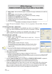
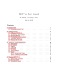
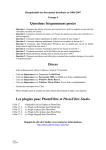
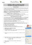
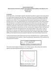
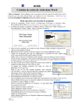
Version 9.0 VisSim/Serial User's Guide By Altair Engineering, Inc. Altair Engineering, Inc. Altair Engineering User’s Guides for VisSim Products - Version 9.0 Copyright © 2015 Altair Engineering, Inc. All rights reserved. Trademarks VisSim, VisSim/Analyze, VisSim/CAN, VisSim/Comm, VisSim/C-Code, VisSim/Digital Power Designer, VisSim/Fixed-Point, VisSim/Knobs and Gauges, VisSim/Motion, VisSim/Neural-Net, VisSim/OPC, VisSim/OptimizePRO, VisSim/real-TimePRO, VisSim/Serial, VisSim/State Charts, and VisSim/UDP are atrademarks of Altair Engineering. IBM, Personal System/2, and PC AT are registered trademarks of International Business Corp. MATLAB is a registered trademark of The MathWorks, Inc. Mathcad is a registered trademark of Mathsoft Corp. Microsoft, MS, MS/DOS, Excel, Windows, Windows is a registered trademarks of Microsoft Corp. NeuroWindow is a trademark of Ward Systems Group, Inc. Other products mentioned in this manual are trademarks or registered trademarks of their respective manufacturers. Copy and use restrictions The information in this manual is subject to change without notice and does not represent a commitment by Altair Engineering. Altair Engineering does not assume responsibility for errors that may appear in this document. Acknowledgments Altair Engineering, Inc. 487 Groton Road Westford, MA 01886 No part of this manual may be reprinted or reproduced or utilized in any form or by any electronic, mechanical, or other means without permission in writing from Altair Engineering. The Software may not be copied or reproduced in any form, except as stated in the terms of the Software license agreement. Portions of VisSim include CVODE code produced by Lawrence Livermore National Laboratory, and require us to notify our users to the following: This software is provided by the copyright holders and contributors “as is” and any express or implied warranties, including, but not limited to, the implied warranties of merchantability and fitness for a particular purpose are disclaimed. In no event shall the regents of the University of California, the U.S. Department of Energy or contributors be liable for any direct, indirect, incidental, special, exemplary, or consequential damages (including, but not limited to, procurement of substitute goods or services; loss of use, data, or profits; or business interruption) however caused and on any theory of liability, whether in contract, strict liability, or tort (including negligence or otherwise) arising in any way out of the use of this software, even if advised of the possibility of such damage. Copyright © 2002, The Regents of the University of California. Produced at the Lawrence Livermore National Laboratory. All rights reserved. Contents Introduction 1 The VisSim product family ....................................................................................................... 1 Resources for learning VisSim/Serial........................................................................................ 3 Interactive webinars .................................................................................................... 3 Sample diagrams ......................................................................................................... 3 Training....................................................................................................................... 3 Installing VisSim/Serial 5 Installation procedure ................................................................................................................ 5 Serial device driver.................................................................................................................... 5 Using VisSim/Serial 7 Serial Config command ............................................................................................................. 7 Serial Read block....................................................................................................................... 7 Serial Write block...................................................................................................................... 8 Index Version 9.0 VisSim/Serial User's Guide 11 Contents iii Introduction VisSim/Serial add-on module interfaces with a standard COMM port on a PC that can be connected to any other serial device. Using VisSim/Serial, you can exchange data between VisSim and any serial device. The VisSim product family The VisSim product family includes several base products and product suites, as well as a comprehensive set of targeted add-on modules that address specific problems in areas such as data communications, data acquisition, linearization and analysis, and digital signal processing. Base products and product suites Product Function Professional VisSim Model-based design, simulation, testing, and validation of dynamic systems. A personal version, VisSim PE, is also available. VisSim PE limits diagram size to 100 blocks. VisSim/Comm Suite Simulates end-to-end communication systems at the signal level using 200+ communications, signal processing, and RF blocks. Includes Professional VisSim and VisSim/Comm blockset. A personal version, VisSim/Comm Suite PE, is also available. VisSim/Comm PE limits diagram size to 100 blocks and limits the Communication blockset. See the VisSim/Comm datasheet for details. VisSim/Comm Suite add-on modules are available for real-time data acquisition (Red Rapids digital tuner card); modeling PCCC turbo codes, including UMTS specification; and for support of Bluetooth, 802.11 a/b/g (Wi-Fi), and ultrawideband wireless designs. VisSim/Embedded Controls Developer Suite Version 9.0 VisSim/Serial User's Guide Rapidly prototypes and creates embedded controls for DSPs, DSCs, and MSP430 microcontrollers. You can simulate and generate scaled, fixed-point ANSI C code, as well as code for on-chip peripherals. Introduction 1 Includes Professional VisSim, VisSim/C-Code, VisSim/Fixed-Point, and one user-specified target support. A personal version, VisSim/Embedded Controls Developer PE, is also available. VisSim/Embedded Controls Developer PE limits diagram size to 100. VisSim Viewer (free) Lets you share VisSim models with colleagues and clients not licensed to use VisSim. Add-on modules Add-On Module Function VisSim/Analyze Performs frequency domain analysis of a linearized nonlinear subsystem. VisSim/CAN Interfaces with a USB CAN device to read and write CAN messages on the CAN bus. VisSim/C-Code Generates highly-optimized, ANSI C code that can be compiled and run on any platform that supports an ANSI C compiler. VisSim/C-Code Support Library Source Provides source code for the Support Library. VisSim/Comm blockset Simulates end-to-end communication systems at the signal level using 200+ communications, signal processing, and RF blocks. A personal version, VisSim/Comm PE, is also available. VisSim/Comm PE is a subset of the Communication blockset. See the VisSim/Comm datasheet for details. You can purchase VisSim/Comm add-on modules for real-time data acquisition (Red Rapids digital tuner cards); for modeling PCCC turbo codes, including UMTS specification; for support of Bluetooth, 802.11 a/b/g (Wi-Fi), and ultrawideband wireless designs. 2 Introduction VisSim/Digital Power Designer Simulates the behavior of fixed-point algorithms prior to code generation and implementation of the algorithm on the fixed-point target. VisSim/Fixed-Point Simulates the behavior of fixed-point algorithms prior to code generation and implementation of the algorithm on the fixed-point target. VisSim/Knobs and Gauges Provides dynamic gauges, meters, and knobs for process control, and measurement and validation systems. VisSim/Model-Wizard Generates transfer function model from historic or realtime data. VisSim/Motion Simulates motor control systems with customizable amplifiers, controllers, filters, motors, sensors, sources, tools, and transforms. VisSim/Neural-Networks Performs nonlinear system identification, problem diagnosis, decision-making prediction, and other problems where pattern recognition is important. VisSim/OPC Connects to any OPC server and log data or run a virtual plant in VisSim for offline tuning. VisSim/OptimizePRO Performs generalized reduced gradient method of Version 9.0 VisSim/Serial User's Guide parameter optimization. VisSim/Real-TimePRO Performs real-time data acquisition and signal generation using I/O cards, PLCs, and DCSs. VisSim/Serial Performs serial I/O with other computers. VisSim/State Charts Creates, edits, and executes event-based systems. VisSim/UDP Performs data exchange over the internet using UDP. VisSim Viewer (free) Lets you share VisSim models with colleagues and clients not licensed to use VisSim. Resources for learning VisSim/Serial For those of you that are new to VisSim, we have provided several free services to make your transition to VisSim fast, smooth, and easy: Interactive webinars Interactive webinars offer you the opportunity to meet with Altair product specialists who will introduce and demonstrate our software products live on your computer and answer any questions you have. Each webinar is approximately 45 minutes long. To learn more about our interactive webinars, go to http://www.vissim.com/webinars/webinars.html. Sample diagrams VisSim 9.0 includes a directory of fully documented sample diagrams. These diagrams illustrate both simple and complex models spanning a broad range of engineering disciplines, including aerospace, biophysics, chemical engineering, control design, dynamic systems, electromechanical systems, environmental systems, HVAC, motion control, process control, and signal processing. To access sample diagrams Click on the Diagrams menu in VisSim. Click on Examples > Applications. Training Altair offers training sessions for learning and gaining expertise in VisSim and the VisSim family of add-on products. Training sessions are conducted at Altair training facility in Westford, MA, as well as at customer sites and as online webinars. For information on setting up a training session, contacts [email protected]. Version 9.0 VisSim/Serial User's Guide Introduction 3 Installing VisSim/Serial This section contains… Installation procedure To install VisSim/Serial Run setupVisSimSerial90.exe. At the completion of the installation the VisSim/Serial add-on will appear in the Addons window for the Edit > Preferences > Addons command, and the VisSim/Serial blocks will appear in the Blocks > Real-Time menu. Serial device driver VisSim/Serial works with the standard PC RS232 serial device. It uses the native PC drivers. No additional driver installation is required. Version 9.0 VisSim/Serial User's Guide Installing VisSim/Serial 5 Using VisSim/Serial VisSim/Serial add-on interfaces with a standard COMM port on a PC that can be connected to any other serial device. Using VisSim/Serial, you can exchange data between VisSim and any serial device using the Serial Read and Serial Write blocks. Serial Config command The Serial Config is used to set the Serial bit rate, parity, byte size and port. Serial Read block The Serial Read block reads data from the serial bus. Version 9.0 VisSim/Serial User's Guide Using VisSim/Serial 7 Port: Specifies port to be used. Block Output: Specifies the information being supplied. There are three possibilities: Data - The current data byte from the receive queue. Receive Queue Length - The current count of bytes in the receive queue. Transmit Queue Length - The current count of bytes in the receive queue. Data Type: If the block output is “Data”, then this controls the data type read. There are 4 possibilities: char – read one byte short – read 2 bytes resulting in a 16 bit integer result long – read 4 bytes resulting in a 32 bit integer result string– read n bytes resulting in a variable length string result If “Start String” is specified, characters are ignored until a match with the start string is found. If “End String” is specified, the string will be terminated at the last character before the match. If “Include Match in Result” is specified, the matched portions of the string will be included in the result; otherwise, they will not be included. Serial Write block The Serial Write block writes data to the Serial bus. The top “enable” pin must have the value 1 in order for the block to send data. The 2nd pin is the data pin. The values presented on the data pins sent to the serial port. If you connect a string type (that is, a quoted constant in the const block), the Serial Write block will transmit all characters in the string for each enable pulse; otherwise, a single byte is sent. 8 Using VisSim/Serial Version 9.0 VisSim/Serial User's Guide Port: Specifies the serial port to which data is written. Version 9.0 VisSim/Serial User's Guide Using VisSim/Serial 9 Index I Installation procedure 5 Installing VisSim/Serial 5 Interactive webinars 3 Introduction 1 R Resources for learning VisSim/Serial 3 S Sample diagrams 3 Serial Config command 7 Serial device driver 5 Serial Read block 7 Serial Write block 8 T The VisSim product family 1 Training 3 U Using VisSim/Serial 7 Version 9.0 VisSim/Serial User's Guide Index 11