1
HP Integrity rx8620 Server User Service
Guide
HP Part Number: A7026-96036_ed7
Published: September 2010
Edition: 7
© Copyright 2003-2010
Legal Notices
The information contained herein is subject to change without notice. The only warranties for HP products and services are set forth in the express
warranty statements accompanying such products and services. Nothing herein should be construed as constituting an additional warranty. HP
shall not be liable for technical or editorial errors or omissions contained herein.
Printed in U.S.A.
Intel, Pentium, Intel Inside, Itanium, and the Intel Inside logo are trademarks or registered trademarks of Intel Corporation or its subsidiaries in
the United States and other countries.
Linux is a U.S. registered trademark of Linus Torvalds.
Microsoft and Windows are U.S. registered trademarks of Microsoft Corporation.
Warranty
To obtain a copy of the warranty for this product see the warranty information website:
http://h20341.www2.hp.com/integrity/w1/en/resources/warranty-information.html
Table of Contents
About This Document.......................................................................................................13
Intended Audience................................................................................................................................13
New and Changed Information in This Edition...................................................................................13
Publishing History................................................................................................................................13
Related Information..............................................................................................................................13
Document Organization.......................................................................................................................14
Typographic Conventions.....................................................................................................................15
HP-UX Release Name and Release Identifier.......................................................................................15
HP contact information.........................................................................................................................16
Documentation feedback......................................................................................................................16
1 Overview.......................................................................................................................17
Introduction..........................................................................................................................................18
Front Panel.......................................................................................................................................19
Front Panel Indicators and Controls..........................................................................................19
Enclosure Status LEDs...............................................................................................................19
System Backplane............................................................................................................................19
I/O Subsystem..................................................................................................................................20
HP Integrity rx8620 Server Block Diagram...........................................................................................20
Cell Board........................................................................................................................................20
PDH Riser Board........................................................................................................................22
Central Processor Units..............................................................................................................22
DIMMS ......................................................................................................................................23
Main Memory Performance.......................................................................................................23
Valid Memory Configurations...................................................................................................23
Cells and nPartitions........................................................................................................................24
Internal Disk Devices for the Server................................................................................................25
System Backplane............................................................................................................................26
System Backplane to Cell Board Connectivity...........................................................................26
System Backplane to Core I/O Card Connectivity.....................................................................27
System Backplane to PCI-X Backplane Connectivity.................................................................27
Clocks and Reset........................................................................................................................27
I/O Subsystem..................................................................................................................................27
Core I/O Card.............................................................................................................................29
Mass Storage (Disk) Backplane..................................................................................................29
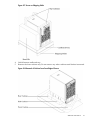
HP Integrity rx8620 Server Description..........................................................................................30
Dimensions and Components....................................................................................................30
2 Installation.....................................................................................................................33
Inspecting the Server Cabinet...............................................................................................................33
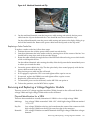
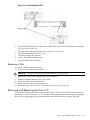
Receiving the Server Cabinet................................................................................................................33
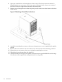
Securing the Cabinet........................................................................................................................36
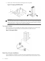
Rack Mount System Installation...........................................................................................................36
Manual Lifting......................................................................................................................................37
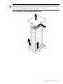
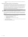
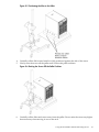
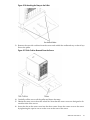
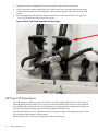
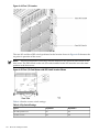
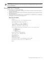
Using the RonI Model 17000 SP 400 Lifting Device.............................................................................38
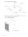
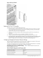
Wheel Kit Installation...........................................................................................................................40
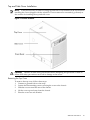
Top and Side Cover Installation......................................................................................................45
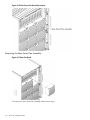
Removing the Top Cover............................................................................................................45
Installing the Top Cover.............................................................................................................46
Table of Contents
3
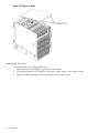
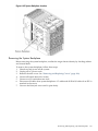
Removing the Side Cover...........................................................................................................47
Installing the Side Cover............................................................................................................47
Power Distribution Unit........................................................................................................................47
3 Installing Accessories...................................................................................................49
Installing Add-On Products..................................................................................................................49
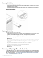
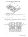
Embedded Disks..............................................................................................................................49
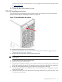
PCI-X Card Cage Assembly I/O Cards............................................................................................50
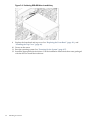
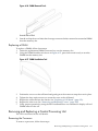
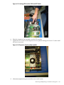
DVD+RW Installation Instructions..................................................................................................55
4 Cabling and Power Up................................................................................................57
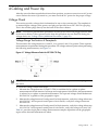
Voltage Check ......................................................................................................................................57
Voltage Check (Additional Procedure).................................................................................................59
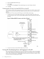
Connecting AC Input Power.................................................................................................................60
Applying Power to the Server.........................................................................................................63
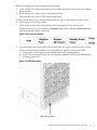
Installing the Line Cord Anchor (rack mounted servers)...............................................................63
Four Cell Server Installation ......................................................................................................63
MP Core I/O Connections.....................................................................................................................64
Setting Up the CE Tool (PC) .................................................................................................................65
Setting CE Tool Parameters.............................................................................................................65
Connecting the CE Tool to the Local RS-232 Port on the MP .........................................................66
Turning On Housekeeping Power and Logging In to the MP..............................................................66
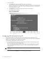
Configuring LAN Information for the MP...........................................................................................68
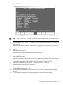
Accessing the Management Processor Using a Web Browser..............................................................70
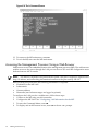
Verifying the Cell Boards .....................................................................................................................71
Configuring AC Line Status.................................................................................................................72
Selecting the System Console................................................................................................................73
VGA Consoles..................................................................................................................................74
Interface Differences Between Itanium-based Systems...................................................................74
MP Consoles....................................................................................................................................74
Other Console Types.......................................................................................................................74
Additional Notes on Console Selection...........................................................................................75
Booting the HP Integrity rx8620 Server ...............................................................................................75
Selecting a Boot Partition Using the Management Processor .........................................................76
Verifying the System Configuration Using the EFI Shell................................................................76
Booting HP-UX Using the EFI Shell................................................................................................76
Adding Processors with Instant Capacity On Demand (iCOD)...........................................................76
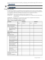
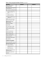
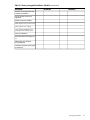
Using the Checklist...............................................................................................................................77
5 Troubleshooting............................................................................................................81
Common Installation Problems............................................................................................................81
The Server Does Not Power On.......................................................................................................81
The Server Powers On But Then Shuts Down With a Fault Light..................................................81
The Server Powers On But Fails Power-On Self Test.......................................................................82
HP Integrity rx8620 Server LED Indicators..........................................................................................82
Front Panel LEDs.............................................................................................................................82
Bulk Power Supply LEDs................................................................................................................82
PCI Power Supply LEDs..................................................................................................................83
System and I/O Fan LEDs................................................................................................................84
OL* LEDs.........................................................................................................................................85
PCI OL* Card Divider LEDs............................................................................................................86
Core I/O LEDs..................................................................................................................................87
Core I/O Buttons..............................................................................................................................89
4
Table of Contents
Interlock Switches............................................................................................................................90
Disk Drive LEDs..............................................................................................................................90
Server Management Subsystem Hardware Overview.........................................................................91
Server Management Overview.............................................................................................................92
Server Management Behavior...............................................................................................................92
Thermal Monitoring........................................................................................................................92
Fan Control......................................................................................................................................93
Power Control..................................................................................................................................94
Server Management Commands..........................................................................................................94
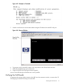
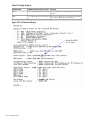
Firmware Updating..............................................................................................................................95
Instructions......................................................................................................................................96
Possible Error Messages..................................................................................................................97
Firmware Update Tool for IPF..............................................................................................................97
Installing and Uninstalling on HP_UX............................................................................................98
Install..........................................................................................................................................98
Uninstall.....................................................................................................................................98
Installing on Linux...........................................................................................................................99
Installing on Windows.....................................................................................................................99
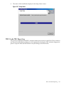
PDC Code FRU Reporting..................................................................................................................101
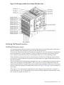
Verifying Cell Board Insertion............................................................................................................103
Cell Board Extraction Levers.........................................................................................................103
6 Removal and Replacement.......................................................................................105
HP Integrity rx8620 Server Field Replaceable Units (FRUs)..............................................................105
Hot-Pluggable FRUs......................................................................................................................105
Hot-Swappable FRUs.....................................................................................................................105
Other FRUs....................................................................................................................................105
Safety and Environmental Considerations ........................................................................................106
Communications Interference ......................................................................................................106
Electrostatic Discharge ..................................................................................................................106
Powering Off Hardware Components and Powering On the Server.................................................106
Powering Off Hardware Components...........................................................................................107
Powering On the System...............................................................................................................107
Removing and Replacing Covers........................................................................................................108
Removing the Top Cover...............................................................................................................108
Replacing the Top Cover................................................................................................................109
Removing the Side Cover..............................................................................................................110
Replacing the Side Cover...............................................................................................................110
Removing the Front Bezel..............................................................................................................111
Replacing the Front Bezel.........................................................................................................111
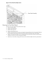
Removing and Replacing the Front Panel Board................................................................................111
Removing the Front Panel Board...................................................................................................112
Replacing the Front Panel Board...................................................................................................113
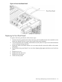
Removing and Replacing the Front Smart Fan Assembly..................................................................114
Preliminary Procedures.................................................................................................................115
Removing the Front Smart Fan Assembly.....................................................................................115
Replacing the Front Smart Fan Assembly.....................................................................................115
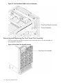
Removing and Replacing the Rear Smart Fan Assembly...................................................................115
Removing the Rear Smart Fan Assembly......................................................................................116
Replacing the Rear Smart Fan Assembly.......................................................................................117
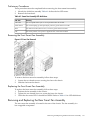
Removing and Replacing a Disk Drive...............................................................................................117
Removing the Disk Drive..............................................................................................................118
Replacing the Disk Drive...............................................................................................................118
Removing and Replacing a Removable Media Drive.........................................................................118
Table of Contents
5
Removing the Removable Media Drive.........................................................................................119
Replacing the Removable Media Drive.........................................................................................120
Removing and Replacing a Cell Board...............................................................................................120
Removing the Cell Board...............................................................................................................121
Replacing a Cell Board...................................................................................................................123
Cell Break-Fix Upgrade and Downgrade Procedure....................................................................124
Upgrading Using the FW Command.......................................................................................124
Upgrading Using the DFW Command....................................................................................132
Downgrading Using the DFW Command...............................................................................134
Installing the VRM Cover (AB388-00002) and Door Opener (AB388-00003).....................................137
Removing and Replacing DIMMs......................................................................................................139
Preliminary Procedures.................................................................................................................139
Removing a DIMM........................................................................................................................140
Replacing a DIMM.........................................................................................................................141
Removing and Replacing a Central Processing Unit..........................................................................141
Removing the Processor................................................................................................................141
Replacing the Processor.................................................................................................................144
Installing Dual-Core CPUs (A9767A)............................................................................................145
Installing Intel Itanium 2 CPUs (AB548A and AB439A)...............................................................148
AB439A and AB548A Processor Stepping Information...........................................................149
CPU Installation Procedures....................................................................................................150
Removing and Replacing a Processor Turbo-Cooler Fan..............................................................153
Removing a Turbo-Cooler Fan.................................................................................................153
Replacing a Turbo-Cooler Fan..................................................................................................155
Removing and Replacing a Voltage Regulator Module.....................................................................155
Removing a VRM...........................................................................................................................156
Replacing a VRM...........................................................................................................................157
Removing and Replacing the Core I/O...............................................................................................157
Removing the Core I/O Assembly.................................................................................................159
Replacing the Core I/O Assembly.................................................................................................161
Configuring Management Processor Network Settings................................................................161
Removing and Replacing a PCI Card.................................................................................................162
Removing the PCI Card ................................................................................................................163
PCI I/O OL* Card Methods......................................................................................................163
Replacing the PCI Card............................................................................................................164
Option ROM..................................................................................................................................165
Removing and Replacing a PCI Smart Fan Assembly........................................................................166
Preliminary Procedures.................................................................................................................166
Removing the PCI Smart Fan Assembly.......................................................................................166
Replacing the PCI Smart Fan Assembly........................................................................................167
Removing and Replacing a PCI Power Supply..................................................................................167
Preliminary Procedures.................................................................................................................168
Removing the PCI Power Supply..................................................................................................169
Replacing the PCI Power Supply...................................................................................................169
Removing and Replacing the PCI-X Card Cage Assembly................................................................169
Preliminary Procedures.................................................................................................................169
Removing the PCI-X Card Cage Assembly...................................................................................170
Replacing the PCI-X Card Cage Assembly....................................................................................171
Removing and Replacing the PCI OLR Assembly..............................................................................172
Removing the PCI OLR Assembly................................................................................................173
Replacing the PCI OLR Assembly.................................................................................................174
Removing and Replacing the PCI-X Voltage Regulator Modules......................................................174
Removing the PCI-X VRM.............................................................................................................175
Replacing the PCI-X VRM.............................................................................................................176
Removing and Replacing a System Backplane...................................................................................176
6
Table of Contents
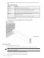
Removing the System Backplane...................................................................................................177
Replacing the System Backplane...................................................................................................178
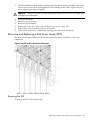
Removing and Replacing a Bulk Power Supply (BPS).......................................................................179
Removing the BPS..........................................................................................................................179
Replacing the BPS..........................................................................................................................180
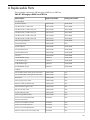
A Replaceable Parts......................................................................................................183
B System Specifications.................................................................................................187
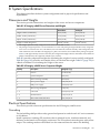
Dimensions and Weights....................................................................................................................187
Electrical Specifications.......................................................................................................................187
Grounding......................................................................................................................................187
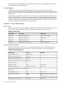
Circuit Breaker...............................................................................................................................188
System AC Power Specifications...................................................................................................188
Power Cords.............................................................................................................................188
System Power Specifications....................................................................................................188
Environmental Specifications.............................................................................................................189
Temperature and Humidity...........................................................................................................189
Operating Environment...........................................................................................................189
Environmental Temperature Sensor........................................................................................189
Non-Operating Environment...................................................................................................189
Cooling...........................................................................................................................................189
Internal Chassis Cooling..........................................................................................................189
Bulk Power Supply Cooling.....................................................................................................190
PCI/Mass Storage Section Cooling...........................................................................................190
Standby Cooling.......................................................................................................................190
Typical Power Dissipation and Cooling........................................................................................190
Acoustic Noise Specification.........................................................................................................191
Air Flow.........................................................................................................................................191
Power Distribution Unit......................................................................................................................191
Weight.................................................................................................................................................192
C MP Commands..........................................................................................................193
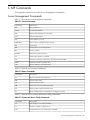
Server Management Commands.........................................................................................................193
D Templates....................................................................................................................195
Equipment Footprint Templates.........................................................................................................195
Computer Room Layout Plan.............................................................................................................195
E Operating System Boot and Shutdown...................................................................203
System Boot Configuration Options...................................................................................................203
Booting HP-UX....................................................................................................................................205
HP-UX Booting..............................................................................................................................205
Single-User Mode HP-UX Booting................................................................................................207
LVM-Maintenance Mode HP-UX Booting.....................................................................................208
Booting the Microsoft Windows Operating System...........................................................................208
Booting the Red Hat Linux Operating System...................................................................................210
Booting the SuSE Linux Enterprise Server Operating System............................................................211
Shutting Down HP-UX.......................................................................................................................212
Shutting Down Microsoft Windows...................................................................................................214
Shutting Down Linux..........................................................................................................................215
Table of Contents
7
Index...............................................................................................................................217
8
Table of Contents
List of Figures
1-1
1-2
1-3
1-4
1-5
1-6
1-7
1-8
1-9
1-10
1-11
1-12
1-13
1-14
2-1
2-2
2-3
2-4
2-5
2-6
2-7
2-8
2-9
2-10
2-11
2-12
2-13
2-14
2-15
2-16
3-1
3-2
3-3
3-4
4-1
4-2
4-3
4-4
4-5
4-6
4-7
4-8
4-9
4-10
4-11
4-12
4-13
4-14
4-15
4-16
4-17
4-18
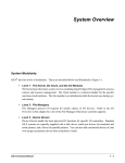
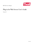
HP Integrity rx8620 Server (front view)........................................................................................18
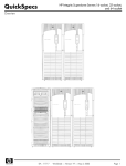
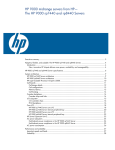
HP Integrity rx8620 Server (front view without bezel).................................................................19
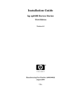
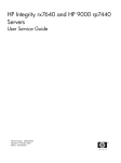
Front Panel LEDs and Power Switch.............................................................................................19
HP Integrity rx8620 Server 16-Socket Block Diagram...................................................................20
Cell Board......................................................................................................................................21
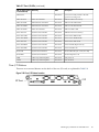
Memory Subsystem.......................................................................................................................22
CPU Locations on Cell Board........................................................................................................23
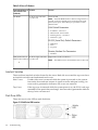
DIMM Slot Layout.........................................................................................................................24
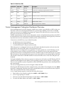
Internal Disks................................................................................................................................25
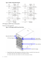
System Backplane Block Diagram.................................................................................................26
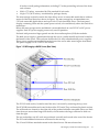
PCI-X Board to Cell Board Block Diagram....................................................................................28
Mass Storage Block Diagram.........................................................................................................30
HP Integrity rx8620 Server (Front View).......................................................................................30
HP Integrity rx8620 Server (Rear View)........................................................................................31
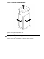
Removing the Polystraps and Cardboard.....................................................................................34
Removing the Shipping Bolts and Plastic Cover...........................................................................35
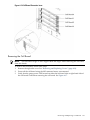
Preparing to Roll Off the Pallet.....................................................................................................36
Securing the Cabinet......................................................................................................................36
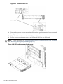
Positioning the Lifter to the Pallet.................................................................................................39
Raising the Server Off the Pallet Cushions....................................................................................39
Server on Shipping Pallet..............................................................................................................41
Removal of Cushion from Front Edge of Server...........................................................................41
Attaching a Caster Wheel to the Server........................................................................................42
Attaching the Ramp to the Pallet..................................................................................................43
Side Cushion Removal From the Server........................................................................................43
Securing Each Caster Cover to the Server.....................................................................................44
Completed Wheel Kit Installation.................................................................................................44
Cover Locations ............................................................................................................................45
Top Cover Detail ...........................................................................................................................46
Side Cover Detail...........................................................................................................................47
Embedded Disks............................................................................................................................49
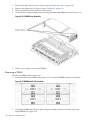
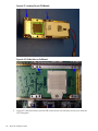
PCI I/O Slot Details........................................................................................................................54
Removable Media Bay Location ...................................................................................................55
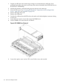
Positioning DVD+RW drive in media bay....................................................................................56
Voltage Reference Points for IEC-320 C19 Plug............................................................................57
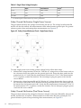
Safety Ground Reference Check - Single Power Source................................................................58
Safety Ground Reference Check - Dual Power Source..................................................................59
Wall Receptacle Pinouts................................................................................................................60
AC Power Input Labeling..............................................................................................................61
Distribution of Input Power for Each Bulk Power Supply............................................................62
Four Cell Line Cord Anchor .........................................................................................................63
Line Cord Anchor and Hook-and-Loop Straps............................................................................64
LAN and RS-232 Connectors on the Core I/O Board ...................................................................66
Front Panel Display ......................................................................................................................67
BPS LED Location..........................................................................................................................67
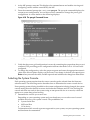
MP Main Menu..............................................................................................................................68
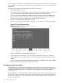
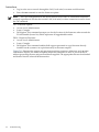
The lc Command Screen................................................................................................................69
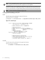
The ls Command Screen................................................................................................................70
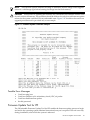
Example sa Command...................................................................................................................71
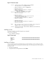
Browser Window...........................................................................................................................71
The du Command Screen..............................................................................................................72
The pwrgrd Command Screen......................................................................................................73
9
4-19
5-1
5-2
5-3
5-4
5-5
5-6
5-7
5-8
5-9
5-10
5-11
5-12
5-13
5-14
5-15
5-16
5-17
5-18
5-19
5-20
6-1
6-2
6-3
6-4
6-5
6-6
6-7
6-8
6-9
6-10
6-11
6-12
6-13
6-14
6-15
6-16
6-17
6-18
6-19
6-20
6-21
6-22
6-23
6-24
6-25
6-26
6-27
6-28
6-29
6-30
6-31
6-32
6-33
6-34
10
Console Output Device menu.......................................................................................................74
Front Panel with LED Indicators...................................................................................................82
BPS LED Location..........................................................................................................................83
PCI Power Supply LED Locations.................................................................................................84
Fan LED Locations........................................................................................................................85
Cell Board LED Locations.............................................................................................................86
PCI OL* LED Locations.................................................................................................................87
Core I/O Card Bulkhead LEDs......................................................................................................88
Core I/O Button Location..............................................................................................................89
Disk Drive LED Location..............................................................................................................90
Temperature States........................................................................................................................93
Firmware Update Command Example.........................................................................................97
swinstall output.............................................................................................................................98
swremove output...........................................................................................................................99
rpm output....................................................................................................................................99
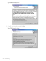
License Agreement......................................................................................................................100
Information Screen......................................................................................................................100
Setup Status.................................................................................................................................101
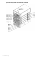
HP Integrity rx8620 Server Cabinet FRUs (Front View).............................................................102
HP Integrity rx8620 Server Cabinet FRUs (Rear View)...............................................................103
de Command Output..................................................................................................................104
Cover Locations ..........................................................................................................................108
Top Cover Removed ...................................................................................................................109
Side Cover Removal Detail..........................................................................................................110
HP Integrity rx8620 Server Bezel Removal and Replacement....................................................111
Front Panel Assembly Location ..................................................................................................112
Front Panel Board Detail.............................................................................................................113
Front Panel Board Cable Location on Backplane........................................................................114
Front Smart Fan Assembly Location ..........................................................................................114
Front Fan Removal ......................................................................................................................115
Rear Smart Fan Assembly Location ............................................................................................116
Rear Fan Detail............................................................................................................................116
Disk Drive Location ....................................................................................................................117
Disk Drive Detail ........................................................................................................................118
Removable Media Drive Location ..............................................................................................119
Removable Media Drive Detail...................................................................................................119
Cell Board Extraction Lever.........................................................................................................121
Cell Board Power LED.................................................................................................................122
Cell Board Removal and Replacement .......................................................................................122
de Command Output..................................................................................................................124
VRM Cover Installed ..................................................................................................................138
Door Opener Installed ................................................................................................................138
VRM Cover, Door Opener and DIMM Cover Installed .............................................................139
Cell Board with DIMM Location.................................................................................................139
DIMM Cover Assembly...............................................................................................................140
DIMM Detail with Locations.......................................................................................................140
DIMM Removal Tools..................................................................................................................141
DIMM Installation Tool...............................................................................................................141
DIMM Cover Removed...............................................................................................................142
CPU Cover Raised.......................................................................................................................143
CPUs with Turbocooler Fans.......................................................................................................143
Locating Pins on CPU Module....................................................................................................146
Guide Holes on Cell Board..........................................................................................................146
Locking CPU Into the Cell Board ZIF Socket..............................................................................147
Sequencer Fan Assembly Installed..............................................................................................147
List of Figures
6-35
6-36
6-37
6-38
6-39
6-40
6-41
6-42
6-43
6-44
6-45
6-46
6-47
6-48
6-49
6-50
6-51
6-52
6-53
6-54
6-55
6-56
6-57
6-58
6-59
6-60
6-61
6-62
6-63
6-64
6-65
6-66
6-67
B-1
D-1
D-2
D-3
D-4
D-5
D-6
D-7
ZIF Socket Lock/Unlock Peep Hole Location..............................................................................150
VRM Cover Installed ..................................................................................................................151
Door Opener Installed ................................................................................................................152
VRM Cover and Door Opener Installed .....................................................................................152
Heatsink with Turbo-Cooler Fan Removed................................................................................154
Soldered Heatsink and Clip........................................................................................................154
Machined Heatsink and Clip.......................................................................................................155
VRM Locations on Cell Board.....................................................................................................156
Cell Board Power LED.................................................................................................................157
Core I/O Location .......................................................................................................................158
Core I/O Card Bottom with DIP Switch Location Shown...........................................................158
PS Command...............................................................................................................................159
DE Command..............................................................................................................................160
Core I/O Detail.............................................................................................................................161
PCI Card Location.......................................................................................................................163
PCI I/O Slot Details......................................................................................................................164
PCI Smart Fan Assembly Location .............................................................................................166
PCI Smart Fan Assembly Detail..................................................................................................167
PCI Power Supply Location ........................................................................................................168
PCI Power Supply Detail.............................................................................................................169
PCI-X Card Cage Assembly Location .........................................................................................170
PCI-X Card Cage Assembly Detail..............................................................................................171
PCI-X Card Assembly Air Baffle.................................................................................................172
PCI OLR Assembly Location (Rear of Server with Top Cover Removed)..................................173
PCI Gate Detail............................................................................................................................173
PCI OLR Assembly Removed......................................................................................................174
VRM Identification......................................................................................................................175
PCI Side Panel..............................................................................................................................176
System Backplane Location ........................................................................................................177
Jack Screw ...................................................................................................................................178
System Backplane Detail.............................................................................................................178
BPS Location (Front Bezel Removed)..........................................................................................179
BPS Detail ...................................................................................................................................180
Airflow Diagram .........................................................................................................................191
HP Integrity rx8620 Server Space Requirements........................................................................195
HP Integrity rx8620 Server Cabinet Template.............................................................................196
Planning Grid..............................................................................................................................197
Planning Grid..............................................................................................................................198
Planning Grid..............................................................................................................................199
Planning Grid..............................................................................................................................200
Planning Grid..............................................................................................................................201
11
List of Tables
1
2
1-1
1-2
1-3
1-4
1-5
1-6
2-1
3-1
3-2
3-3
3-4
4-1
4-2
4-3
5-1
5-2
5-3
5-4
5-5
5-6
5-7
5-8
5-9
5-10
5-11
5-12
5-13
6-1
6-2
6-3
6-4
6-5
6-6
6-7
6-8
A-1
B-1
B-2
B-3
B-4
B-5
B-6
B-7
C-1
C-2
C-3
12
Publishing History Details............................................................................................................13
HP-UX 11i Releases.......................................................................................................................15
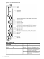
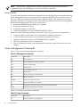
Cell Board CPU Load Order..........................................................................................................22
HP Integrity rx8620 Server DIMMs ..............................................................................................23
DIMM Load Order........................................................................................................................24
Removable Media Drive Path........................................................................................................25
Hard Disk Drive Path....................................................................................................................26
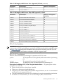
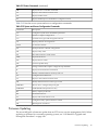
PCI-X Slot Types............................................................................................................................28
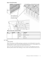
Wheel Kit Packing List..................................................................................................................40
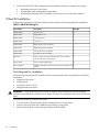
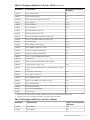
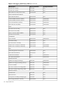
HP Integrity rx8620 Server I/O Cards - HP-UX............................................................................50
HP Integrity rx8620 Server I/O Cards - Windows.........................................................................51
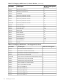
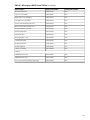
HP Integrity rx8620 Server - Linux Supported I/O Cards.............................................................52
HP Integrity rx8620 Server - Open VMS Supported I/O Cards....................................................53
Single Phase Voltage Examples.....................................................................................................58
BPS to Cell Board Configuration to Achieve N+1.........................................................................62
Factory-Integrated Installation Checklist......................................................................................77
Front Panel LEDs...........................................................................................................................82
BPS LEDs.......................................................................................................................................83
PCI Power Supply LEDs................................................................................................................84
Front, Rear, and I/O Fan LEDs......................................................................................................85
Cell Board OL* LED Indicators.....................................................................................................86
OL* LED States..............................................................................................................................87
Core I/O LEDs...............................................................................................................................88
Core I/O Buttons............................................................................................................................90
Disk Drive LEDs............................................................................................................................91
Management Commands..............................................................................................................94
Status Commands..........................................................................................................................94
System and Access Configuration Commands.............................................................................95
Ready Bit States...........................................................................................................................104
Smart Fan Assembly LED definitions.........................................................................................115
Smart Fan Assembly LED Indications.........................................................................................117
Processor Stepping Comparisons................................................................................................149
Dip Switch Settings......................................................................................................................158
Default Configuration for MP Customer LAN...........................................................................161
Smart Fan Assembly LED Indications.........................................................................................166
PCI Power Supply LED Indications............................................................................................168
BPS LED definitions....................................................................................................................180
HP Integrity rx8620 Server FRU List...........................................................................................183
HP Integrity rx8620 Server Dimensions and Weights.................................................................187
HP Integrity rx8620 Server Component Weights........................................................................187
Power Cords................................................................................................................................188
Power Requirements....................................................................................................................188
Typical HP Integrity rx8620 Server Configurations....................................................................190
Example Weight Summary..........................................................................................................192
Weight Summary.........................................................................................................................192
Service Commands......................................................................................................................193
Status Commands........................................................................................................................193
System and Access Config Commands.......................................................................................193
List of Tables
About This Document
This document provides information and instructions on servicing and troubleshooting the HP
Integrity rx8620 server.
The document printing date and part number indicate the document’s current edition. The
publish date changes when a new edition is published. Minor changes can be made at reprint
without changing the publishing date. The document part number changes when extensive
changes are made.
Document updates can be issued between editions to correct errors or document product changes.
To ensure that you receive the updated or new editions, you should subscribe to the appropriate
product support service. See your HP sales representative for details.
The latest version of this document can be found on line at the following website:
http://h20000.www2.hp.com/bizsupport/TechSupport/Home.jsp
Intended Audience
This document is intended to provide technical product and support information for authorized
service providers, system administrators, and HP support personnel.
This document is not a tutorial.
New and Changed Information in This Edition
This guide has been updated for greater usability.
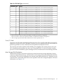
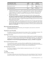
Publishing History
The publishing history below identifies the edition dates of this manual. Updates are made to
this publication on an unscheduled, as needed, basis.
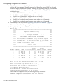
Table 1 Publishing History Details
Document
Manufacturing Part
Number
Operating Systems
Supported
Supported Product Versions
Publication Date
A7026-96003
HP-UX, Windows, Linux,
OpenVMS
rx8620
September 2003
A7026-96009
HP-UX, Windows, Linux,
OpenVMS
rx8620
November 2003
A7026-96018
HP-UX, Windows, Linux,
OpenVMS
rx8620
May 2004
A7026-96026
HP-UX, Windows, Linux,
OpenVMS
rx8620
October 2006
A7026-96036
HP-UX, Windows, Linux,
OpenVMS
rx8620
May 2007
A7026-96036–ed6
HP-UX, Windows, Linux,
OpenVMS
rx8620
October 2009
A7026–96036_ed7
HP-UX, Windows, Linux,
OpenVMS
rx8620
September 2010
Related Information
You can access other information on HP server hardware management, Microsoft® Windows®
administratuon, and diagnostic support tools at the following Web sites:
Intended Audience
13
Documentation:
bizsupport.
The main Web site for HP technical documentation is http://www.hp.com/go/
Server Hardware Information: The following website offers more system information: http://
www.hp.com/go/integrity_servers-docs. It provides HP nPartition server hardware management
information, including site preparation, installation, and more.
Windows Operating System Information: You can find information about administration of the
Microsoft® Windows® operating system at the following Web sites, among others:
• http://docs.hp.com/windows_nt/
• http://www.microsoft.com/technet/
Diagnostics and Event Monitoring: Hardware Support Tools: Complete information about HP
hardware support tools, including online and offline diagnostics and event monitoring tools, is
at the www.hp.com/go/bizsupport Web site. This site has manuals, tutorials, FAQs, and
other reference material.
Web Site for HP Technical Support:
HP IT resource center located at the following website:
http://www13.itrc.hp.com/service/home/home.do?admit
It provides comprehensive support information for IT professionals on a wide variety of topics,
including software, hardware, and networking.
Document Organization
This guide is divided into the following chapters.
14
Chapter 1
Overview Use this chapter to learn about the features and specifications of the
HP Integrity rx8620 server.
Chapter 2
Installation Use this chapter to learn how to unpack and install the server.
Chapter 3
Installing Accessories Use this chapter to learn how to install add-on products.
Chapter 4
Cabling and Powering On Use this chapter to learn how to connect the cables and
power the server on.
Chapter 5
Troubleshooting Use this chapter to learn about troubleshooting problems you
may encounter with the server.
Chapter 6
Removal and Replacement Use this chapter to learn how to remove and replace
the various components of the server
Appendix A
Parts Information This appendix provides server part number information.
Appendix B
System Specifications This appendix provides physical dimensions and the
electrical specifications for the server.
Appendix C
MP Commands This appendix provides the MP commands available for use on
the HP Integrity rx 8620 server.
Appendix D
Templates This appendix provides templates for installing the server into a data
center.
Appendix E
Operating System Boot and Shutdown Use this appendix to learn about booting
and shutting down the operating system on the server.
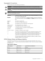
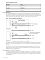
Typographic Conventions
This document uses the following conventions.
WARNING!
A warning lists requirements that you must meet to avoid personal injury.
CAUTION: A caution provides information required to avoid losing data or avoid losing system
functionality.
NOTE: A note highlights useful information such as restrictions, recommendations, or important
details about HP product features.
Book Title
The title of a book. On the Web and on the Instant Information CD, it may
be a hot link to the book itself.
KeyCap
The name of a keyboard key or graphical interface item (such as buttons,
tabs, and menu items). Note that Return and Enter both refer to the same
key.
Emphasis
Text that is emphasized.
Bold
Text that is strongly emphasized.
Bold
The defined use of an important word or phrase.
ComputerOut
Text displayed by the computer.
UserInput
Commands and other text that you type.
Command
A command name or qualified command phrase.
Option
An available option.
Screen Output
Example of computer screen output.
[]
The contents are optional in formats and command descriptions. If the
contents are a list separated by |, you must select one of the items.
{}
The contents are required in formats and command descriptions. If the
contents are a list separated by |, you must select one of the items.
...
The preceding element may be repeated an arbitrary number of times.
|
Separates items in a list of choices.
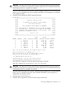
HP-UX Release Name and Release Identifier
Each HP-UX 11i release has an associated release name and release identifier. The uname(1)
command with the -r option returns the release identifier. Table 2 shows the releases available
for HP-UX 11i.
Table 2 HP-UX 11i Releases
Release Identifier
Release Name
Supported Processor Architecture
B.11.11
HP-UX 11i v1
PA-RISC
B.11.20
HP-UX 11i v1.5
Intel® Itanium®
B.11.22
HP-UX 11i v1.6
Intel Itanium
B.11.23
HP-UX 11i v2.0
Intel Itanium
Typographic Conventions
15
HP contact information
For the name of the nearest HP authorized reseller:
•
•
In the United States, see the HP US service locator webpage (http://welcome.hp.com/country/
us/en/wwcontact.html.)
In other locations, see the Contact HP worldwide (in English) webpage:
http://welcome.hp.com/country/us/en/wwcontact.html.
For HP technical support:
•
In the United States, for contact options see the Contact HP United States webpage: (http://
welcome.hp.com/country/us/en/contact_us.html)
To contact HP by phone:
— Call 1-800-HP-INVENT (1-800-474-6836). This service is available 24 hours a day, 7 days
a week. For continuous quality improvement, calls may be recorded or monitored.
— If you have purchased a Care Pack (service upgrade), call 1-800-633-3600. For more
information about Care Packs, see the HP website: (http://www.hp.com/hps).
•
In other locations, see the Contact HP worldwide (in English) webpage (http://
welcome.hp.com/country/us/en/wwcontact.html)
Documentation feedback
HP welcomes your feedback. To make comments and suggestions about product documentation,
send a message to [email protected].
Include the document title and manufacturing part number. All submissions become the property
of HP
16
1 Overview
The HP Integrity rx8620 server is a member of the HP business-critical computing platform
family mid-range, mid-volume servers positioned between the HP Integrity rx7620 and HP
Integrity Superdome servers.
17
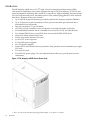
Introduction
The HP Integrity rx8620 server is 17U1 high, 16-socket symmetric multiprocessor (SMP)
rack-mount or standalone servers that accommodate up to 128 GB of memory, PCI-X I/O, and
internal peripherals including disks and DVD or tape drives. High-availability features include
N+1 hot-swap fans and power, redundant power cords, and hot-pluggable PCI cards and hard
disk drives. Features of the server include:
•
•
•
•
•
•
•
•
•
•
•
•
•
•
Up to 128 GB of physical memory provided by dual in-line memory modules (DIMMs).
Up to 32 processors with a maximum of four processor modules per cell board and a
maximum of four cell boards.
One cell controller (CC) per cell board
All CPUs and cell controllers on the cell boards are cooled with turbo cooler fans
Four embedded hard disk drives. Available sizes are 36 GB, 73 GB, and 146 GB drives
Two internal DVD drives or one DVD drive and one 40 GB DDS-4 DAT drive
Nine front chassis mounted N+1 fans
Twelve rear chassis mounted N+1 fans
Six N+1 PCI-X card cage fans
Six N+1 bulk power supplies
Two PCI power supplies.
Sixteen PCI-X slots divided into two partitions. Each partition can accommodate up to eight
PCI cards
Two core I/O cards
Four 220 VAC power plugs. Two are required and the other two provide power source
redundancy
Figure 1-1 HP Integrity rx8620 Server (front view)
1. The U is a unit of measurement specifying product height. 1 U is equal to 1.75 inches.
18
Overview
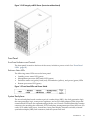
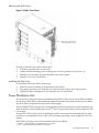
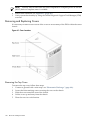
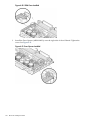
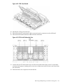
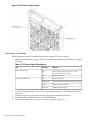
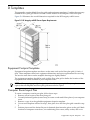
Figure 1-2 HP Integrity rx8620 Server (front view without bezel)
Front Panel
Front Panel Indicators and Controls
The front panel, located on the front of the server, includes a power switch. See “Front Panel
LEDs” (page 82).
Enclosure Status LEDs
The following status LEDs are on the front panel:
•
•
•
•
Standby power status LED (green)
Management processor (MP) status LED (green)
Enclosure status run (green), fault (red), and attention (yellow), and power (green) LEDs
Remote port status LED (green)
Figure 1-3 Front Panel LEDs and Power Switch
System Backplane
The server backplane board contains a pair of crossbar chips (XBC), the clock generation logic,
the reset generation logic, some power regulators, and two local bus adapter (LBA) chips that
create internal PCI buses for communicating with the core I/O cards. The backplane also contains
connectors for attaching the cell boards, PCI-X backplane, management processor (MP) core I/O
cards, SCSI cables, bulk power, chassis fans, front panel display, intrusion switches, external
system bus adaptor (SBA) link connectors, and the system scan card.
Introduction
19
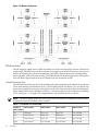
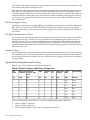
I/O Subsystem
All of the I/O is integrated into the system by way of the PCI busses. The CC on each cell board
communicates with one SBA over the SBA link. The SBA link consists of both an inbound and
an outbound link with an effective bandwidth of approximately 1 GB per second. The SBA
converts the SBA link protocol into ropes. A rope is defined as a high-speed, point-to-point data
bus. The SBA can support up to 16 of these high-speed bi-directional links for a total aggregate
bandwidth of approximately 4 GB per second. The server supports a maximum of two SBAs
with the capability of supporting an additional two SBAs in an externally connected I/O cabinet
known as the HP Server Expansion Unit.
There are LBA chips on the PCI-X backplane that act as a bus bridge, supporting either one or
two ropes and capable of driving 33 MHz or 66 MHz for PCI cards. The LBAs can also drive at
66 MHz or 133 MHz for PCI-X cards.
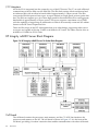
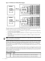
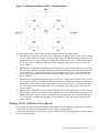
HP Integrity rx8620 Server Block Diagram
Figure 1-4 HP Integrity rx8620 Server 16-Socket Block Diagram
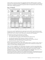
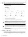
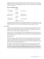
Cell Board
The cell board contains the processors, main memory, and the CC ASIC that interfaces the
processors and memory to the I/O. The cell board is shown in Figure 1-5. It is the heart of the
cell board, providing a crossbar connection that enables communication with other cell boards
20
Overview
in the system. It connects to the processor dependent hardware (PDH) and micro controller
hardware. Each cell board holds up to 16 DIMMS. Between one to four cell boards can be installed
in the server. A cell board can be selectively powered off for cell replacement without affecting
cells in other configured partitions.
Figure 1-5 Cell Board
The server has a 48 V distributed power system and receives the 48 V power from the system
backplane board. The cell board contains DC-to-DC converters to generate the required voltage
rails. The DC-to-DC converters on the cell board do not provide N+1 redundancy.
The cell board contains several major buses including:
•
•
•
•
•
Front side buses (FSB) for each of the four processors
Two memory buses (one going to each half of the main memory array)
Incoming and outgoing I/O bus that goes off board to a SBA chip
Incoming and outgoing crossbar bus that goes off board to the other cell board
PDH bus that goes to the PDH and micro controller circuitry
All of these buses come together at the CC chip.
Because of space limitations on the cell board, the PDH and micro controller circuitry reside on
a riser board that plugs at a right angle into the cell board. The cell board also includes clock
circuits, test circuits, and de-coupling capacitors.
Figure 1-6 shows a simplified view of the memory subsystem. It consists of two independent
access paths, each path having its own address bus, control bus, data bus, and DIMMs . In practice,
the CC runs the two paths 180 degrees out of phase with respect to each other to facilitate
pipelining in the CC. Address and control signals are fanned out through register ports to the
synchronous dynamic random access memory (SDRAM) on the DIMMs.
The memory subsystem is composed of four independent quadrants. Each quadrant has its own
memory data bus connecting from the cell controller to the two buffers for the memory quadrant.
Each quadrant also has two memory control buses; one for each buffer.
HP Integrity rx8620 Server Block Diagram
21
Figure 1-6 Memory Subsystem
PDH Riser Board
The HP Integrity rx8620 Server PDH riser board is a small card that plugs into the cell board at
a right angle. The PDH riser interface contains a microprocessor memory interface microcircuit,
hardware including the processor dependant code (PDC) flash memory, and a manageability
microcontroller with associated circuitry. The PDH obtains cell board configuration information
from cell board signals and from the cell board local power module (LPM).
Central Processor Units
The cell board can hold up to four CPU modules and can be populated with modules in increments
of one after meeting the minimum of two CPUs installed on the cell board. On a cell board, the
processors must be the same type and speed. For the CPU load order that must be maintained
when adding CPUs to the cell board, see Table 1-1. For the locations on the cell board for installing
CPUs, seeFigure 1-7. A single CPU configuration is not available for the cell board.
NOTE: When installing dual-core CPUs, if only one CPU module is installed on the cell board,
a terminator must be installed in CPU socket 2.
Table 1-1 Cell Board CPU Load Order
22
Number of
CPUs Installed
CPU 2 Location
CPU 3 Location
CPU 1 Location
CPU 0 Location
Two
Terminator
Empty slot
Empty slot
CPU installed
Four
CPU installed
Empty slot
Empty slot
CPU installed
Six
CPU installed
Empty slot
CPU installed
CPU installed
Eight
CPU installed
CPU installed
CPU installed
CPU installed
Overview
Figure 1-7 CPU Locations on Cell Board
DIMMS
The memory DIMMs used by the server are custom designed by HP and are identical to those
used in the Superdome servers. Each DIMM contains SDRAM memory components and is
qualified to run at 125 MHz. The CPU chip set does not support traditional DRAMs.
The server supports DIMMs with densities of 64, 128, 256, and 512 Mb for the SDRAM devices.
Table 1-2 shows each supported DIMM size, the resulting total server capacity, and the memory
component density. Each DIMM is connected to two buffer chips on the cell board.
Table 1-2 HP Integrity rx8620 Server DIMMs
DIMM Size
Total HP Integrity rx8620 Server
Capacity
Memory Component Density
256 MB
16 GB
64 Mb
512 MB
32 GB
128 Mb
1 GB
64 GB
256 Mb
2 GB
128 GB
512 Mb
4 GB
256 GB
1024 Mb
Main Memory Performance
Latency to main memory is an important parameter in determining overall system performance.
For a server with memory busses at 125 MHz, the latency for a page hit is 8.5 cycles (68 ns), the
latency for a page closed is 11.5 cycles (92 ns), and the latency for a page miss is 14.5 cycles (116
ns).
Valid Memory Configurations
The server is capable of supporting as little as 0.5 GB of main memory using two 256 MB DIMMs
installed on one of the cell boards and as much as 128 GB by filling all 16 DIMM slots on all four
cell boards with 2 GB DIMMs.
DIMMs must be loaded in sets of two at specified locations on the cell board. Two DIMMs are
called an “echelon”, so two echelons would be equivalent to four DIMMs, three echelons would
be equivalent to six DIMMs and so on. The DIMMs must be the same size in an echelon. The
HP Integrity rx8620 Server Block Diagram
23
DIMMs across all cells in a partition should have identical memory loaded. Figure 1-8 shows the
DIMM slot layout on the cell board. For DIMM load order and the DIMM layout on the cell
board, see Table 1-3 and Figure 1-8.
A quad, as seen in Figure 1-8, is a grouping of four DIMMs. Configurations with 8 or 16 DIMM
slots loaded are recommended. The DIMM sizes in a quad can be different, but the DIMMs in
an echelon must be the same size.
Table 1-3 DIMM Load Order
Number of DIMMs Installed
Action Taken
DIMM Location on Cell Quad Location
Board
2 DIMMs = 1 Echelon
Install First
0A and 0B
Quad 0
4 DIMMs = 2 Echelons
Add Second
1A and 1B
Quad 1
6 DIMMs = 3 Echelons
Add Third
2A and 2B
Quad 2
8 DIMMs = 4 Echelons
Add Fourth
3A and 3B
Quad 3
10 DIMMs = 5 Echelons
Add Fifth
4A and 4B
Quad 0
12 DIMMs = 6 Echelons
Add Sixth
5A and 5B
Quad 1
14 DIMMs = 7 Echelons
Add Seventh
6A and 6B
Quad 2
16 DIMMs = 8 Echelons
Add Last
7A and 7B
Quad 3
Figure 1-8 DIMM Slot Layout
Cells and nPartitions
An nPartition has one or more cells (containing processors and memory) that are assigned to the
nPartition for its exclusive use. Any I/O chassis that is attached to a cell belonging to an nPartition
24
Overview
also is assigned to the nPartition. Each I/O chassis has PCI card slots plus any I/O cards and
attached devices, and has a core I/O card assigned to the I/O chassis.
On the HP Integrity rx8620 Server, each nPartition has its own dedicated portion of the server
hardware that can run a single instance of the operating system. Each nPartition can boot, reboot,
and operate independently of any other nPartitions and hardware within the same server complex.
The server complex includes all hardware within an nPartition server: all cabinets, cells, I/O
chassis, I/O devices and racks, management and interconnecting hardware, power supplies, and
fans.
One or more nPartitions may be configured within a server complex, enabling the hardware to
function as a single operating system or as many systems.
NOTE:
Partition configuration information is available on the HP website at http://hp.com
For details, see HP System Partitions Guide: Administration for nPartitions.
Internal Disk Devices for the Server
As Figure 1-9 shows, in the server cabinet, the top internal disk drives connect to cell 0 through
the core I/O for cell 0. The bottom internal disk drives connect to cell 1 through the core I/O for
cell 1.
The upper removable media drive connects to cell 0 through the core I/O card for cell 0 and the
lower removable media drive connects to cell 1 through the core I/O card for cell 1.
Figure 1-9 Internal Disks
Table 1-4 Removable Media Drive Path
Removable Media
Path
Slot 0 Media
0/0/0/2/1.x1.0
Slot 1 Media
1/0/0/2/1.x1.0
1
X equals 2 for a DVD drive while X equals 3 for a DDS-4 DAT drive.
HP Integrity rx8620 Server Block Diagram
25
Table 1-5 Hard Disk Drive Path
Hard Drive
Path
Slot 0 Drive
0/0/0/2/0.6.0
Slot 1 Drive
0/0/0/3/0.6.0
Slot 2 Drive
1/0/0/2/0.6.0
Slot 3 Drive
1/0/0/3/0.6.0
System Backplane
The system backplane houses the system clock generation logic, the system reset generation
logic, DC-to-DC converters, power monitor logic, and two LBA link-to-PCI converter ASICs. It
is the point of connection for the cell boards, PCI-X backplane, core I/O cards, SCSI cables, bulk
power, chassis fans, front panel display, intrusion switches, and the system scan card.
Figure 1-10 System Backplane Block Diagram
The LBA PCI bus controllers are placed on the system backplane to facilitate hot-plug capability
for the core I/O cards. The partition for the core I/O card must be shut down before removing
the card.
Having the SCSI connectors on the system backplane enables hot-plug for the core I/O card
without having to remove cables in the process. Hot-plug circuitry is located near the system
backplane/core I/O card mating area.
System Backplane to Cell Board Connectivity
Four sets of vertical connectors serve as the point of connection for the cell boards. In addition,
two vertical connectors per cell board carry signals from the CC on the cell board to the SBA
chip on the PCI-X backplane, or an external I/O chassis PCI-X backplane, and back through the
system backplane.
26
Overview
System Backplane to Core I/O Card Connectivity
The core I/O card connectors are right-angle connectors that mate with the system backplane.
Three connectors per core I/O card carry one PCI bus from the system to the core I/O board and
three single-ended SCSI busses from the core I/O to the system backplane. The system backplane
contains two LBA PCI bus controllers, one per core I/O board, and six 68-pin SCSI connectors
(three per core I/O board).
The LBA PCI bus controllers are placed on the system backplane to facilitate removal of the core
I/O cards when standby power is on. The partition for the core I/O card must be shut down
before removing the card.
Placement of the SCSI connectors on the system backplane also permits removal of a core I/O
card without having to remove cables in the process. Hot-plug circuitry is located near the system
backplane/core I/O card mating area.
System Backplane to PCI-X Backplane Connectivity
The PCI-X backplane uses two connectors for the SBA link bus and two connectors for the
high-speed data signals and the manageability signals.
SBA link bus signals are routed through the system backplane to the cell controller on each
corresponding cell board.
The high-speed data signals are routed from the SBA chips on the PCI-X backplane to the two
LBA PCI bus controllers on the system backplane.
Clocks and Reset
The system backplane contains reset and clock circuitry that propagates through the whole
system. The system backplane central clocks drive all major chip set clocks.
I/O Subsystem
The cell board to the PCI-X board path runs from the CC to the SBA, from the SBA to the ropes,
from the ropes to the LBA, and from the LBA to the PCI slots seen in Figure 1-11. The CC on cell
board 0 and cell board 1 communicates through an SBA over the SBA link. The SBA link consists
of both an inbound and an outbound link with an effective bandwidth of approximately 1 GB
per second. The SBA converts the SBA link protocol into ropes. A rope is defined as a high-speed,
point-to-point data bus. The SBA can support up to 16 of these high-speed bi-directional rope
links for a total aggregate bandwidth of approximately 4 GB per second. Each LBA acts as a bus
bridge, supporting either one or two ropes and capable of driving 33 MHz or 66 MHz for PCI
cards. The LBAs can also drive at 66 MHz or 133 MHz for PCI-X cards. When cell board 2 and
cell board 3 are present, the cell boards attach to their own associated SBA and LBA chips on the
PCI-X board in the Server Expansion Unit.
HP Integrity rx8620 Server Block Diagram
27
Figure 1-11 PCI-X Board to Cell Board Block Diagram
The server supports two internal SBAs. The SBAs generate 32 rope buses (16 per SBA). The 32
available internal rope buses are divided in the following manner:
• Two ropes are routed as single rope bundles to support the core I/O boards through LBAs
located on the core I/O backplane.
• Two ropes are routed as single rope bundles to two LBAs to support two slots for PCI and
PCI-X cards.
• Twenty eight ropes are bundled in two rope pairs to 14 LBAs to support 14 slots for PCI
and PCI-X cards.
NOTE: PCI-X slots 1-7 are dual rope slots while slot 8 is a single rope slot. A rope is defined as
a high-speed, point-to-point data bus.
The PCI-X backplane is the primary I/O interface for the server. It provides 16 64-bit, hot-plug
PCI/PCI-X slots. Fourteen of the slots have dual ropes connected to the LBA chips. The remaining
two slots have a single rope connected to each LBA chip. Each of the 16 slots is capable of 66
MHz/33 MHz PCI or 133 MHz/66 MHz PCI-X. All 16 PCI slots are keyed for 3.3 V connectors
(accepting both Universal and 3.3 V cards). The PCI-X backplane does not provide any 5 V slots
for the I/O cards.
The PCI-X backplane is physically one board but behaves like two independent partitions. SBA
0 and its associated LBAs and eight PCI-X slots form one I/O partition. SBA 1 and its associated
LBAs and eight PCI-X slots form the other I/O partition. One I/O partition can be powered down
separate from the other I/O partition.
Table 1-6 PCI-X Slot Types
I/O Partition Slot
28
Device1
0
82
PCI (33 or 66 MHz) / PCI-X (66 or 133 MHz) 64-bit, 3.3 V connector, Hot-Plug Slot.
0
7
PCI (33 or 66 MHz) / PCI-X (66 or 133 MHz) 64-bit, 3.3 V connector, Hot-Plug Slot.
Overview
Table 1-6 PCI-X Slot Types (continued)
I/O Partition Slot
Device1
0
6
PCI (33 or 66 MHz) / PCI-X (66 or 133 MHz) 64-bit, 3.3 V connector, Hot-Plug Slot.
0
5
PCI (33 or 66 MHz) / PCI-X (66 or 133 MHz) 64-bit, 3.3 V connector, Hot-Plug Slot.
0
4
PCI (33 or 66 MHz) / PCI-X (66 or 133 MHz) 64-bit, 3.3 V connector, Hot-Plug Slot.
0
3
PCI (33 or 66 MHz) / PCI-X (66 or 133 MHz) 64-bit, 3.3 V connector, Hot-Plug Slot.
0
2
PCI (33 or 66 MHz) / PCI-X (66 or 133 MHz) 64-bit, 3.3 V connector, Hot-Plug Slot.
0
1
PCI (33 or 66 MHz) / PCI-X (66 or 133 MHz) 64-bit, 3.3 V connector, Hot-Plug Slot.
1
82
PCI (33 or 66 MHz) / PCI-X (66 or 133 MHz) 64-bit, 3.3 V connector, Hot-Plug Slot.
1
7
PCI (33 or 66 MHz) / PCI-X (66 or 133 MHz) 64-bit, 3.3 V connector, Hot-Plug Slot.
1
6
PCI (33 or 66 MHz) / PCI-X (66 or 133 MHz) 64-bit, 3.3 V connector, Hot-Plug Slot.
1
5
PCI (33 or 66 MHz) / PCI-X (66 or 133 MHz) 64-bit, 3.3 V connector, Hot-Plug Slot.
1
4
PCI (33 or 66 MHz) / PCI-X (66 or 133 MHz) 64-bit, 3.3 V connector, Hot-Plug Slot.
1
3
PCI (33 or 66 MHz) / PCI-X (66 or 133 MHz) 64-bit, 3.3 V connector, Hot-Plug Slot.
1
2
PCI (33 or 66 MHz) / PCI-X (66 or 133 MHz) 64-bit, 3.3 V connector, Hot-Plug Slot.
1
1
PCI (33 or 66 MHz) / PCI-X (66 or 133 MHz) 64-bit, 3.3 V connector, Hot-Plug Slot.
1
2
If the slot is used as a PCI slot, either the 33 MHz or 66 MHz PCI frequency is supported.
If the slot is used as a PCI-X slot, either the 66 MHz or 133 MHz PCI-X frequency is supported.
This is a single rope between the SBA and LBA and not a dual rope like ropes 1–7.
Core I/O Card
Up to two core I/O cards can be plugged into the server. Two core I/O cards allows for two I/O
partitions to exist in the server. The server can have up to two partitions but the total number of
partitions possible in a server with the Server Expansion Unit attached is four.
The core I/O card can be replaced with standby power applied. The system power to the core
I/O is handled in the hardware the same way a hot-plug PCI/PCI-X card is handled. Standby
power to core I/O is handled by power manager devices to limit inrush current during insertion.
Mass Storage (Disk) Backplane
Internal mass storage connections to disks are routed on the mass storage backplane, having
connectors and termination logic. All hard disks are hot-plug while removable media disks are
not hot-plug. The server accommodates two internal, removable media devices. Therefore, power
connectors for a removable media device are required on the mass storage backplane. For more
information, see Figure 1-12.
HP Integrity rx8620 Server Block Diagram
29
Figure 1-12 Mass Storage Block Diagram
HP Integrity rx8620 Server Description
Dimensions and Components
Figure 1-13 HP Integrity rx8620 Server (Front View)
•
Depth: Defined by cable management constraints to fit into a standard 36-inch deep rack:
25.5 inches from front rack column to PCI connector surface
26.7 inches from front rack column to core I/O card connector surface
30
Overview
30 inches overall package dimension, including 2.7 inches protruding in front of the front
rack columns
•
•
Width: 17.5 inches, constrained by EIA standard 19 inch racks
Height: 17U (29.55 inches), constrained by package density
The mass storage section located in the front allows access to removable media drives without
removal of the bezel (bezel not shown in figure). The mass storage bay accommodates two
5.25-inch removable media drives and up to four 3.5-inch hard disk drives. The front panel
display, containing LEDs and the system power switch, is located directly above the hard drive
media bays.
Below the mass storage section and behind a removable bezel are two PCI DC-to-DC power
supplies. Each PCI power supply powers only one I/O partition.
Enclosed with protective finger guards are nine front online replace (OLR) fan modules.
The bulk power supply is partitioned through the use of a sealed metallic enclosure located in
the bottom of the server. This enclosure houses the N+1 fully redundant bulk power supplies.
These power supplies are installed from the front of the server after removing the front bezel.
The power supply is 2.45 X 5.625 X 20.0 inches.
Figure 1-14 HP Integrity rx8620 Server (Rear View)
The PCI I/O card section, located toward the rear, is accessed by removing the top cover.
The PCI OLR fan modules are located in front of the PCI cards. They are housed in plastic carriers.
The cell boards are located on the right side of the product behind a removable side cover. Rack
front doors are more often hinged on the left, which restricts the large cell board to slide out
from the right.
The two redundant core I/O cards are positioned vertically end-to-end at the rear of the chassis.
The PCI card bulkhead connectors are located at the rear top.
The 12 rear OLR fans attached external to the chassis house 120-mm exhaust fans.
HP Integrity rx8620 Server Block Diagram
31
Redundant line cords attach to the AC power receptacles at the bottom rear. Two 20-amp cords
are required to power the server. Two additional line cords provide redundancy.
Access the system backplane by removing the left side cover. The system backplane hinges from
the lower edge and is anchored at the top with a single large jack screw assembly.
The SCSI ribbon cable assembly also routes across and fastens to the backside of the system
backplane near the connectors that attach the core I/O boards.
The blue deployment handles hinge outward to help lift and move the server into a rack.
32
Overview
2 Installation
Inspect shipping containers when the equipment arrives at the site. Check equipment after the
packing has been removed. This chapter discusses how to inspect and receive the HP Integrity
rx8620 Server.
Inspecting the Server Cabinet
NOTE: The server ships in one of three different configurations. The configurations are as
follows:
• On a pallet installed in a server cabinet
• On a pallet for rack mount into an existing cabinet on the customer site
• On a pallet with a wheel kit for installation as a standalone server
HP shipping containers are designed to protect their contents under normal shipping conditions.
After the equipment arrives at the customer site, carefully inspect each carton for signs of shipping
damage. A tilt indicator is installed on each carton shipped. The beads in the indicator roll to the
upper position if the container has been tilted to an angle that could cause equipment damage.
The tilt indicator has two windows, and each window under normal conditions shows four
beads. If a carton has been mishandled, accidentally dropped, or knocked against something,
beads would be missing from the tilt indicator. If damage is found, document the damage with
photographs and contact the transport carrier immediately.
Examine the server cabinet for visible shipping damage. After unpacking the cabinet, check for
damage that may have been obscured by the shipping container. If damage is found after visual
inspection, document the damage with photographs and contact the transport carrier immediately.
If the equipment has any damage, a damage claim form must be obtained by the customer from
the shipping representative. The customer should complete the form and return it to the shipping
representative.
NOTE: The factory provides an installation warranty that is effective from the time the customer
receives the shipment until Field Services turns the system over to the customer.
Upon inspection of a received system and during installation of the system, if any parts or
accessories are missing or defective, they will be replaced directly from the factory by a priority
process. To request replacement parts, the HP Installation Specialist must contact the local Order
Fulfillment group which will coordinate the replacement with the factory.
Receiving the Server Cabinet
This section contains information about unpacking the server cabinet.
WARNING! Wear protective glasses while cutting the plastic bands around the shipping
container. These bands are under tension. When cut, they can spring back and cause serious eye
injury.
NOTE: Position the pallet, allowing for enough space to roll the cabinet off the pallet before
starting.
To remove the server cabinet from the shipping container, follow these steps:
1.
2.
Cut the polystrap bands around the shipping container.
Lift the cardboard top cap from the shipping box.
Inspecting the Server Cabinet
33
Figure 2-1 Removing the Polystraps and Cardboard
3.
4.
Remove the corrugated wrap from the pallet.
Remove the packing materials.
CAUTION: The plastic wrapping material should be cut off rather than pulled off. Pulling
off the plastic covering represents an ESD hazard.
5.
34
Remove the four bolts that hold down the ramps and remove the ramps.
Installation
NOTE: Figure 2-2 shows one ramp attached to the pallet on either side of the cabinet with
each ramp secured to the pallet using two bolts. There is another configuration where the
ramps are secured together on one side of the cabinet with one bolt.
Figure 2-2 Removing the Shipping Bolts and Plastic Cover
Receiving the Server Cabinet
35
6.
Remove the six bolts from the base attaching the rack to the pallet.
Figure 2-3 Preparing to Roll Off the Pallet
WARNING! Be sure that the leveling feet on the rack are raised before you roll the rack
down the ramp, and any time you roll the rack on the casters. Use caution when rolling the
cabinet off the ramp. A single server in the cabinet weighs approximately 508 lb. It is strongly
recommended that two people roll the cabinet off the pallet.
Securing the Cabinet
When in position, secure and stabilize the cabinet using the leveling feet at the corners of the
base and install the anti-tip mechanisms on the bottom front and rear of the rack.
Figure 2-4 Securing the Cabinet
Rack Mount System Installation
Servers shipped as a standalone or in the to-be-racked configuration must have the core I/O
handles and the PCI towel bars attached at system installation. Obtain and install the core I/O
36
Installation
handles and PCI towel bars from the accessory kit A6093-04046. The towel bars and handles are
the same part. See service note A6093A-11.
There are several documents written to help with rack mounting the server. This list is intended
to guide the HP Installation Specialist to the documentation that has been written by the Rack
Solutions team.
Rack System/E
Detailed rack information for the rack system/E covers the following topics:
•
•
•
•
Safety and Regulatory Information
Description of the Standard Racks and Physical Specifications
Installation Guidelines
Procedures
Rack System/E Stabilizer Feet
The stabilizer installation guide for the rack system/E covers the following topics:
•
•
How to Install the Stabilizers
Moving the Rack
HP J1528A Rack Integration Kit
The rack integration kit information covers installing the following products:
•
•
•
•
•
Ballast Kit (J1479A)
Anti-Tip Stabilizer Kit (A5540A)
Slide Rails
CMA (Cable Management Arm)
Interlock Device Assembly
This installation guide provides a complete parts list of the hardware and tools required to
perform the installation of the products mentioned. Installation of the products is illustrated in
this guide.
Manual Lifting
Use this procedure only if no HP approved lift is available.
This procedure should only be performed by four qualified HP Service Personnel utilizing proper
lifting techniques and procedures.
System damage can occur through improper removal and re-installation of devices. This task
must be performed by trained personnel only. Instructions for removing and re-installing these
components can be found in Chapter 6 (page 105).
CAUTION: Observe all ESD safety precautions before attempting this procedure. Failure to
follow ESD safety precautions can result in damage to the server.
To manually lift the server, follow these steps:
1. Reduce the weight by removing all bulk power supplies and cell boards.
2. Locate the four (4) positioning handles on the sides of the system. They are color coded blue
and located close to each base corner of the unit.
3. Ensure the vertical support brackets are in the down position so they rest on the slides when
the server is lowered to the rack slides. There are two brackets on each side of the server
chassis.
4. Unfold the handles so they are extended out from the unit. The server is now ready for
manual lifting by the four qualified HP Service Personnel.
Manual Lifting
37
5.
After the server is secured, re-install the previously removed cell boards and bulk power
supplies.
Using the RonI Model 17000 SP 400 Lifting Device
A lifter designed by the RonI company is used to rack mount the server. The lifter can raise 400
lb. to a height of five feet. The lifter can be broken down into several components. When
completely broken down, no single component weighs more than 25 lb. The ability to break the
lifter down makes it easy to transport from the office to the car and then to the customer site.
Documentation for the RonI lifter has been written by RonI and is on the HP intranet at the
Cybrary website. Complete details on how to assemble the lifter, troubleshoot the lifter, and
maintain the lifter are provided in the RonI documentation.
To unload the server from the pallet after the lifter is assembled, follow these steps:
WARNING! Use caution when using the lifter. Because of the weight of the server, it must be
centered on the lifter forks before raising it off the pallet to avoid injury.
The server must be racked in the bottom of a cabinet for safety reasons. Never extend more than
one server from the same cabinet while installing or servicing either an HP Integrity rx8620
Server or another server product. Failure to follow these instructions can result in the cabinet
tipping over.
1.
Obtain the HP J1528A Rack Integration Kit Installation Guide before proceeding with the rack
mount procedure. This guide covers these important steps:
• Installing the anti-tip stabilizer kit (A5540A)
• Installing the ballast kit (J1479A)
• Installing the barrel nuts on the front and rear columns
• Installing the slides
2.
To remove the banding and carton top from the server pallet, follow the instructions on the
outside of the server packaging.
Insert the lifter forks between the cushions.
3.
38
Installation
Figure 2-5 Positioning the Lifter to the Pallet
4.
5.
Carefully roll the lift forward until it is fully positioned against the side of the server.
Slowly raise the server off the pallet until it clears the pallet cushions.
Figure 2-6 Raising the Server Off the Pallet Cushions
6.
Carefully roll the lifter and server away from the pallet. Do not raise the server any higher
than necessary when moving it over to the rack.
Using the RonI Model 17000 SP 400 Lifting Device
39
7.
Follow the HP J1528A Rack Integration Kit Installation Guide to complete these steps:
• Mounting the server to the slides
• Installing the cable management arm (CMA)
• Installing the interlock device assembly (if two servers are in the same cabinet)
Wheel Kit Installation
Compare the packing list with the contents of the wheel kit before beginning the installation.
Table 2-1 Wheel Kit Packing List
Part Number
Description
Quantity
A9904-04002
Caster Cover
2
A9904-04007
Right Side Cover
1
A9904-04008
Left Side Cover
1
A9904-04009
Top Cover
1
A6093-04082
Right Front Caster Assembly
1
A6093-04083
Right Rear Caster Assembly
1
A6093-04084
Left Front Caster Assembly
1
A6093-04085
Left Rear Caster Assembly
1
0515-2478
M4 x 0.7 8mm T15 Steel Zinc Machine Screw (Used to
attach each caster to the chassis)
8
A6093-44013
Plywood Unloading Ramp
1
Not Applicable
Phillips Head Wood Screw (used to attach the ramp to the 2
pallet)
Tools Required for Installation
The following list provides the installer with the recommended tools to perform the wheel kit
installation.
•
•
•
•
Diagonal side cutters
Safety glasses
Torx driver with T-15 bit
Phillips head screwdriver
WARNING! Wear protective glasses while cutting the plastic bands around the shipping
container. These bands are under tension. When cut, they can spring back and cause serious eye
injury.
To install the wheel kit, follow these steps:
1.
2.
3.
40
Cut and remove the polystrap bands securing the server to the pallet.
Lift the carton top from the cardboard tray resting on the pallet.
Remove the bezel kit carton and top cushion from the pallet.
Installation
Figure 2-7 Server on Shipping Pallet
4.
5.
Unfold bottom cardboard tray.
Remove the front cushion only. Do not remove any other cushions until further instructed.
Figure 2-8 Removal of Cushion from Front Edge of Server
Wheel Kit Installation
41
6.
7.
Open the wheel kit box and locate the two front casters. The front casters are shorter in
length than the two rear casters. Each front caster is designed to fit only on one corner of
the server. There is a right front caster and a left front caster.
Remove two of the eight screws from the plastic pouch. Attach one wheel caster to the front
of the server.
Figure 2-9 Attaching a Caster Wheel to the Server
8.
Attach the remaining front caster to the server using two more screws supplied in the plastic
pouch.
9. Remove the rear cushion at the rear of the server. Do not remove the remaining cushions.
10. Mount the two rear casters to the server using the remaining four screws.
11. Obtain the plywood ramp from the wheel kit.
12. Attach the ramp to the edge of the pallet. Note there are two pre-drilled holes in the ramp.
Use the two screws taped to the ramp and attach it to the pallet.
42
Installation
Figure 2-10 Attaching the Ramp to the Pallet
13. Remove the two side cushions from the server and unfold the cardboard tray so that it lays
flat on the pallet.
Figure 2-11 Side Cushion Removal From the Server
14. Carefully roll the server off the pallet and down the ramp.
15. Obtain the caster covers from the wheel kit. Note that the caster covers are designed to fit
on either side of the server.
16. Insert the slot on the caster cover into the front caster. Secure the caster cover to the server
by tightening the captive screw on the cover at the rear of the server.
Wheel Kit Installation
43
Figure 2-12 Securing Each Caster Cover to the Server
17. Wheel kit installation is complete after both caster covers are attached to the server and the
bezel cover is snapped into place on the front of the server.
Figure 2-13 Completed Wheel Kit Installation
44
Installation
Top and Side Cover Installation
NOTE: It may be necessary to remove existing top and side covers installed on the server before
installing the covers shipped with the wheel kit. If cover removal is not needed, go directly to
the sections for installing the top and side cover.
Figure 2-14 Cover Locations
CAUTION: Observe all ESD safety precautions before attempting this procedure. Failure to
follow ESD safety precautions can result in damage to the server.
Removing the Top Cover
To remove the top cover, follow these steps:
1. Connect to ground with a wrist strap.
2. Loosen the blue retaining screws securing the cover to the chassis.
3. Slide the cover toward the rear of the chassis.
4. Lift the cover up and away from the chassis.
5. Place the cover in a safe location.
Wheel Kit Installation
45
Figure 2-15 Top Cover Detail
Installing the Top Cover
To install the top cover, follow these steps:
1. Orient the cover according to its position on the chassis.
2. To properly seat the cover, slide the cover into position using a slow, firm pressure.
3. Tighten the blue retaining screws securing the cover to the chassis.
46
Installation
Removing the Side Cover
Figure 2-16 Side Cover Detail
To remove the side cover, follow these steps:
1. Connect to ground with a wrist strap.
2. Loosen the blue retaining screw securing the cover to the chassis. See Figure 2-16.
3. Slide the cover from the chassis toward the rear of the system.
4. Place the cover in a safe location.
Installing the Side Cover
To install the side cover, follow these steps:
1. Orient the cover according to its position on the chassis.
2. To properly seat the cover, slide the cover into position using a slow, firm pressure.
3. Tighten the blue retaining screw securing the cover to the chassis.
Power Distribution Unit
The server may ship with a power distribution unit (PDU). There are two 60 A PDUs available
for the server. Each PDU is mounted horizontally between the rear columns of the server cabinet.
The 60 A PDUs are delivered with an IEC-309 60A plug.
The 60A NEMA2 PDU has four 20A circuit breakers and is constructed for North American use.
Each of the four circuit breakers has two IEC3-320 C19 outlets providing a total of eight IEC-320
C19 outlets.
The 60A IEC PDU has four 16A circuit breakers and is constructed for International use. Each
of the four circuit breakers has two IEC-320 C19 outlets providing a total of eight IEC-320 C19
outlets.
Each PDU is 3U high and is rack-mounted in the server cabinet.
2. NEMA — National Electrical Manufacturers Association
3. IEC — International Electrotechnical Commission
Power Distribution Unit
47
Documentation for installation will accompany the PDU. The documentation can also be found
at the external Rack Solutions website at http://www.hp.com/racksolutions. This PDU
might be referred to as a Relocatable Power Tap outside HP.
The PDU installation kit contains the following:
•
•
•
48
PDU with cord and plug
Mounting hardware
Installation instructions
Installation
3 Installing Accessories
The following options can be installed in the HP Integrity rx8620 Server:
• PCI I/O cards
• Additional hard disk drive storage
• Additional removable media device storage
Installing Add-On Products
CAUTION: Observe all ESD safety precautions before attempting these procedures. Failure to
follow ESD safety precautions can result in damage to the server.
This section provides information on additional products ordered after installation and any
dependencies for these add-on products.
Embedded Disks
When disks are installed, the top two hard disk drives are driven by cell 0 located in the server.
The bottom two hard disk drives are driven by cell 1 located in the server.
A list of replacement disk drives for the server is in Appendix A (page 183). The list contains both
removable media disk drives and hard disk drives.
Figure 3-1 Embedded Disks
Hard Disk Drive Installation
The disk drives are located in the front of the chassis. The hard disk drives are hot-pluggable
drives.
To install the hard disk drives, follow these steps:
1. Be sure the front locking latch is open, then position the disk drive in the chassis.
Installing Add-On Products
49
2.
3.
4.
Slide the disk drive into the chassis; a slow, firm pressure is needed to properly seat the
connector.
To secure the disk drive in the chassis, press the front locking latch.
Spin up the disk by entering one of the following commands:
#diskinfo -v /dev/rdsk/cxtxdx
#ioscan -f
Removable Media Drive Installation
The DVD drive or DDS-4 tape drive is located in the front of the chassis. You must turn off the
server power before attempting to install it. For more information , see .“Powering Off Hardware
Components and Powering On the Server” (page 106)
If an upper drive is installed, you must remove it before installing a lower drive.
To remove the media drive, follow these steps:
1. Remove filler panel.
2. Connect the cables to the rear of the drive.
3. Install left and right media rails and clips.
4. Slide the drive in the chassis. Fold the cables out of the way.
5. The drive easily slides into the chassis; however, a slow, firm pressure is needed for proper
seating.
6. The front locking tab latches to secure the drive in the chassis.
PCI-X Card Cage Assembly I/O Cards
A number of PCI and PCI-X I/O cards are supported in the server. Known supported cards at
the release of this manual are shown in Tables 3-1 through 3-4.
Table 3-1 HP Integrity rx8620 Server I/O Cards - HP-UX
50
Part Number
Card Description
Number of Cards Supported
(B-Bootable)
A3739B
FDDI Dual Attach
16
A4926A
Gigabit Ethernet (1000B-SX)
16
A4929A
Gigabit Ethernet (1000B-T)
16
A6847A
Next Generation 1000B-SX
161
A6825A
Next Generation 1000B-T
16???
A6826A
PCI-X Dual Channel 2 GB Fibre Channel HBA
16???
A5149A
Ultra2 SCSI
16
A5150A
2-port Ultra2 SCSI
16
A5158A
Fibre Channel PCI Adapter
162
A5230A
10/100B-TX (RJ45)
16
A5506B
4-port 10/100B-TX
16
A5513A
ATM 155 (MMF connector)
16
A5783A
Token Ring (4/16/100 Mb/s)
16
A5838A
2-port Ultra2-SCSI + 2-port 100T
16
A6386A
Hyperfabric II
8
A6826A
PCI-X Dual Channel 2Gb Fibre Channel HBA
16???
Installing Accessories
Table 3-1 HP Integrity rx8620 Server I/O Cards - HP-UX (continued)
Part Number
Card Description
Number of Cards Supported
(B-Bootable)
A6748A
8-port Terminal MUX
16
A6749A
64-port Terminal MUX
16
A6794AX
Procurium GigE LAN/SCSI combo card
2B
A6795A
2G FC Tachlite
16???
A6828A
1-port U160 SCSI
16???
A6829A
2-port U160 SCSI
16???
A6869A
Obsidian USB/VGA PCI card
1
A6869B
Obsidian USB/VGA PCI card
1
A7011A
PCI-X 2 port 1000BaseSX Dual Port (Intel chip)
16
A7012A
PCI-X 2 port 1000BaseT Dual Port (Intel chip)
16
A7173A
2 port U320 SCSI
16B
A9782A
PCI-X 1000B-T GB FC GigE-SX
16???
A9784A
PCI-X 1000B-T GigE/2 G FC combo
16???
A9890A
SmartArray 6402 2-channel RAID
8B
A9891A
SmartArray 6404 4-channel RAID
8B
AB286A
PCI-X 2 port 4X InfiniBand HCA (HPC)
2
AB287A
10G Ethernet
2
AB286C
PCI-X 2-Port 4X InfiniBand HCA (HPC), RoHS
1
AB290A
U320 SCSI/GigE Combo Card
16B
AB345C
PCI-X 2-Port 4X InfiniBand HCA w/ HA and Database Support,
RoHS
1
AB378A
1-port 4Gb FC card PCI-X
16B
AB379A
2-port 4Gb FC card PCI-X
16
AB545A
4-port 1000B-T Ethernet
16
AB465A
PCI-X 2-port 1000B-T/2-port 2Gb FC Combo
16B
AD278A
8-port Terminal MUX
15
AD279A
64-port Terminal MUX
15
J3525A
2-port serial (X25/FR/SDLC)
16
Z7340A
8-port PCI ACC
16
1
2
Supports a pre-OS network boot (IODC or EFI) for the purpose of OS installation (ignite, RIS).
This I/O card is supported at the first update of the HP-UX B.11.23 release.
Table 3-2 HP Integrity rx8620 Server I/O Cards - Windows
Part Number
Card Description
Number of Cards Supported
(B-Bootable)
A7059A
SCSI adapter
8B
A7060A
SCSI adapter
8B
Installing Add-On Products
51
Table 3-2 HP Integrity rx8620 Server I/O Cards - Windows (continued)
Part Number
Card Description
Number of Cards Supported
(B-Bootable)
A6869A
Obsidian VGA/USB card
1
A6869B
Obsidian 2 VGA/USB card
1
A7173A
SCSI adapter
8B
A9825A
Smart Array 5302 SCSI controller
8B
A9826A
Smart Array 5304 SCSI controller
8B
A9890A
Smart Array 6402 SCSI controller
8B
A9891A
Smart Array 6404 SCSI controller
8
337972-B21
Smart Array P600 SCSI controller
8
AB232A
FC Emulex 9802
12B
AB466A
FC Emulex 1050DC
8B
AB467A
FC Emulex 1050
12B
AD167A
Emulex 4GB
12
AD168
Exulex 4GB DC
8
A7061A
NIC Broadcom Cu
12
A7073A
NIC Broadcom FC
12
A9900A
NIC Intel Dual Cu
12B
A9899A
NIC Intel Dual FC
12B
AB287A
10G NIC
4
Table 3-3 HP Integrity rx8620 Server - Linux Supported I/O Cards
52
Part Number
Card Description
Number of Cards Supported
A7173A
PCI-X Dual-Channel Ultra320 SCSI
8
A7059A
PCI Windows and Linux Ultra160 SCSI
8
A7060A
PCI Windows and Linux 2 channel Ultra160 SCSI
5
A9890A
PCI-X SmartArray 6402/128 MB
8
337972-B21
PCI-X Smart Array P600 serial attached SCSI (SAS) controller 8
A9825A
2 channel Smart Array 5302 / 128 MB
8
A9826A
4 channel Smart Array 6404 / 256 MB
8
A6826A
PCI X 2 channel 2 Gb /s Fibre Channel
8
A7538A
PCI-X 1-port 2Gb Fibre Channel
15
A7061A
PCI 1 port 1000Base T
8
A7073A
PCI 1 port 1000Base SX
8
A5506B
PCI 4-port 100Base-TX
2
A9899A
PCI 2-port 1000Base-SX
8
A9900A
PCI 2-port 1000Base-T
8
Installing Accessories
Table 3-3 HP Integrity rx8620 Server - Linux Supported I/O Cards (continued)
Part Number
Card Description
Number of Cards Supported
AD144A
PCI 1-port 10GbE SR (133Mhz)
2
AD145A
PCI 4-port 1000Base-T
4
Table 3-4 HP Integrity rx8620 Server - Open VMS Supported I/O Cards
Part Number
Card Description
Number of Cards Supported
(B-Bootable)
A6826A
PCI X 2 channel 2 Gb /s Fibre Channel
8B
A7173A
PCI 2 channel Ultra320 SCSI Adapter
2B
AB378A
PCI 1 port 4 Gb Fibre Channel
8B
AB379A
PCI 2 port 4 Gb Fibre Channel
8B
AB545A
PCI X 4 port 1000Base T Gigabit Adapter
3
A6847A
PCI 1 port 1000Base SX
8
A6825A
PCI 1 port 1000Base T
8
A7011A
PCI X 2 port 1000Base SX
8
A7012A
PCI X 2 port 1000Base T
8
A9782A
PCI X 2 Gb Fibre Channel, 1000Base SX
4B
A9784A
PCI X 2 Gb Fibre Channel, 1000Base T
4B
AB465A
PCI X 2 port 2 Gb FC/2 port 1 Gb Ethernet
2B
AB290A
PCI X 2 port 1000Base T/2 port Ultra320 SCSI
2B
PCI I/O Card Installation
IMPORTANT: The installation process varies depending on what method for installing the PCI
card you select. PCI I/O card installation procedures should be downloaded from the HP website
at http://hp.com. Background information and procedures for adding a new PCI I/O card
using online addition are found in the Interface Card OL* Support Guide.
PCI I/O OL* Card Methods
There are three methods for performing OL* operations on PCI I/O cards.
pdweb
The Peripheral Device Tool (pdweb) Web-based method of performing
OL*.
olrad
The command line method of performing OL*.
Attention Button
The hardware system slot based method of performing OL*.
Prerequisites for Adding a PCI I/O Card Using the Attention Button
procedure are as follows:
•
•
•
•
•
The prerequisites for this
Drivers for the card have already been installed.
There are no drivers associated with the slot.
The green power LED is steady Off. Should the empty slot be on, use the olrad command
or the pdweb tool to power the slot off
The yellow attention LED is steady Off or is blinking if a user has requested the slot location.
For details on card installation, see the host bus adapter (HBA) documentation.
Installing Add-On Products
53
•
•
To determine the status of all the PCI I/O slots, run the olrad -q command.
For instructions on preparing the operating system for the online addition of the PCI I/O
card before attempting to insert a PCI I/O card into the PCI-X card cage assembly backplane
slot, obtain a copy of the interface card guide.
This procedure describes how to perform an online addition of a PCI card using the attention
button for cards whose drivers support online add or replacement (OLAR). The attention button
is also referred to as the doorbell.
To install a PCI I/O card, follow these procedures:
1. Remove the top cover.
2. Remove the PCI bulkhead filler panel.
3. Flip the PCI gate for the card slot to the open position. See Figure 3-2.
4. Install the new PCI card in the slot.
NOTE:
5.
To properly seat the card into the backplane, use a slow, firm pressure.
Flip the PCI gate for the card slot to the closed position.
CAUTION: Working out of sequence or not completing the actions within each step could
cause the system to crash.
Do not press the attention button until the latch is locked.
6.
Press the attention button.
The green power LED starts to blink.
Figure 3-2 PCI I/O Slot Details
7.
8.
Wait for the green power LED to stop blinking and turn on solid.
Check for errors in the hotplugd daemon log file (default: /var/adm/hotplugd.log).
The critical resource analysis (CRA) performed while doing an attention button initiated
add action is very restrictive and the action will not complete–it will fail–to protect critical
resources from being impacted. For finer control over CRA actions use pdweb or the olrad
54
Installing Accessories
command. For details, see the Interface Card OL* Support Guide located on the HP website
at http://hp.com.
9. Replace the top cover.
10. Connect all cables to the installed PCI card.
DVD+RW Installation Instructions
The CD/DVD/DAT is located in the front of the chassis. The system power to this component
must be removed before attempting to remove or replace it.
Figure 3-3 Removable Media Bay Location
To install the DVD+RW drive, follow these steps:
1. Remove the front bezel and top cover. See “Removing the Front Bezel” (page 111), and
“Removing the Top Cover” (page 45).
2. Remove the drive bay blank or removable media drive.
NOTE: You must remove the upper removable media drive to access the lower removable
media drive.
3.
4.
5.
6.
7.
8.
Remove the DVD+RW drive from package.
Install the side rails onto the drive.
Connect the removable media bay power cable to the loose end of the Y power cable on the
DVD+RW assembly. Ensure that the mating connector pair passes through the ruggedizer.
Route the removable media bay power cable into the ruggedizer cable clip.
Connect the SCSI cable to the DVD+RW dive. Ensure that the power cable passes over the
top of the SCSI cable.
Slide the DVD+RW drive and cable into the removable media drive bay. Push the drive until
it is fully seated in the bay.
Installing Add-On Products
55
Figure 3-4 Positioning DVD+RW drive in media bay
9.
Replace the front bezel and top cover. See “Replacing the Front Bezel” (page 111), and
“Installing the Top Cover” (page 46).
10. Power on the server.
11. Boot the operating system. See “Powering On the System” (page 107).
12. Install the appropriate device drivers. Use the installation instructions that come packaged
with the drive to install device drivers.
56
Installing Accessories
4 Cabling and Power Up
After the server has been unpacked and moved into position, you must connect it to an AC power
source. Before the server is powered on, you must check the AC power for the proper voltage.
Voltage Check
This section provides voltage check information for use on the customer site. The emphasis is
on measuring the voltages at the power cord plug end specified as an IEC-320 C19 type plug.
This is the end that plugs directly into the back of the server cabinet.
NOTE: You need to perform these procedures for each power cord to be plugged into the back
of the server cabinet. If the expected results from this procedure are not observed during the
voltage check, see “Voltage Check (Additional Procedure)” (page 59).
Voltage Range Verification of Receptacle
This measures the voltage between L1 and L2, L1 to ground, and L2 to ground. Three separate
measurements are performed during this procedure. For voltage reference points when performing
the following measurements, see Figure 4-1.
Figure 4-1 Voltage Reference Points for IEC-320 C19 Plug
IMPORTANT:
the server.
These measurements must be performed for every power cord that plugs into
To check the voltage, follow these steps:
1.
2.
3.
Measure the voltage between L1 and L2. This is considered to be a phase-to-phase
measurement in North America. In Europe and certain parts of Asia-Pacific, this measurement
is referred to as a phase-to-neutral measurement. The expected voltage should be between
200–240 VAC regardless of the geographic region.
Measure the voltage between L1 and ground. In North America, verify this voltage is between
100–120 VAC. In Europe and certain parts of Asia-Pacific, verify this voltage is between
200–240 VAC.
Measure the voltage between L2 and ground. In North America, verify this voltage is between
100–120 VAC. In Europe and certain parts of Asia-Pacific, verify this voltage is 0 (zero) VAC.
Table 4-1 provides single phase voltage measurement examples dependent on the geographic
region where these measurements are taken.
Voltage Check
57
Table 4-1 Single Phase Voltage Examples
Japan
North America
Europe1
L1-L2
210V
208V or 240V
230V
L1-GND
105V
120V
230V
L2-GND
105V
120V
0V
1
In some European countries there may not be a polarization.
Safety Ground Verification (Single Power Source)
This procedure measures the voltage level between A0 and A1. The voltage level between B0
and B1 will also be verified. All measurements will be taken between ground pins. For ground
reference points when performing these measurements, see Figure 4-2.
Figure 4-2 Safety Ground Reference Check - Single Power Source
To verify single power source safety ground voltage levels, follow these steps:
1.
2.
Measure the voltage between A0 and A1. Take the AC voltage down to the lowest scale on
the volt meter. Insert one probe into the ground pin for A0. Insert the other probe into the
ground pin for A1. Verify that the measurement is between 0–5 VAC. If the measurement
is 5 V or greater, escalate the situation. Do not attempt to plug the power cords into the
server cabinet.
Measure the voltage between B0 and B1. Take the AC voltage down to the lowest scale on
the volt meter. One probe will be inserted into the ground pin for B0. The other probe will
be inserted into the ground pin for B1. Verify that the measurement is between 0–5 VAC. If
the measurement is 5 V or greater, escalate the situation. Do not attempt to plug the power
cords into the server cabinet.
Safety Ground Verification (Dual Power Source)
This procedure measures the voltage level between A0 and A1, between B0 and B1, between A0
and B0, and between A1 and B1. All measurements will be taken between ground pins. For
ground reference points when performing these measurements, see Figure 4-3.
58
Cabling and Power Up
Figure 4-3 Safety Ground Reference Check - Dual Power Source
To verify dual power source safety ground voltage levels, follow these steps:
1.
2.
3.
4.
Measure the voltage between A0 and A1. Take the AC voltage down to the lowest scale on
the volt meter. Insert one probe into the ground pin for A0. Insert the other probe into the
ground pin for A1. Verify that the measurement is between 0–5 VAC. If the measurement
is 5 V or greater, escalate the situation. Do not attempt to plug the power cords into the
server cabinet.
Measure the voltage between B0 and B1. Take the AC voltage down to the lowest scale on
the volt meter. Insert one probe into the ground pin for B0. Insert the other probe into the
ground pin for B1. Verify that the measurement is between 0–5 VAC. If the measurement
is 5 V or greater, escalate the situation. Do not attempt to plug the power cords into the
server cabinet.
Measure the voltage between A0 and B0. Take the AC voltage down to the lowest scale on
the volt meter. Insert one probe into the ground pin for A0. Insert the other probe into the
ground pin for B0. Verify that the measurement is between 0–5 VAC. If the measurement
is 5 V or greater, escalate the situation. Do not attempt to plug the power cords into the
server cabinet.
Measure the voltage between A1 and B1. Take the AC voltage down to the lowest scale on
the volt meter. Insert one probe into the ground pin for A1. Insert the other probe into the
ground pin for B1. Verify that the measurement is between 0–5 VAC. If the measurement
is 5 V or greater, escalate the situation. Do not attempt to plug the power cords into the
server cabinet.
Voltage Check (Additional Procedure)
The voltage check ensures that all phases (and neutral, for international systems) are connected
correctly to the cabinet and that the AC input voltage is within limits.
Perform this procedure if the previous voltage check procedure did not yield the expected results
as previously outlined.
Voltage Check (Additional Procedure)
59
NOTE: If a UPS is used, refer to applicable UPS documentation for information on connecting
the server and checking the UPS output voltage. UPS User Manual documentation is shipped
with the UPS. Documentation may also be found at http://www.hp.com/racksolutions
To check the voltage, follow these steps:
1. Verify that site power is off.
2. Open the site circuit breakers.
3. Verify that the receptacle ground connector is connected to ground. Refer to Figure 4-4 for
connector details.
4. Set the site power circuit breaker to on.
Figure 4-4 Wall Receptacle Pinouts
5.
6.
7.
8.
Verify that the voltage between receptacle pins x and y is between 200–240 VAC.
Set the site power circuit breaker to off.
Ensure that power is removed from the server.
Route and connect the server power connector to the site power receptacle.
• For locking type receptacles, line up the key on the plug with the groove in the receptacle.
• Push the plug into the receptacle and rotate to lock the connector in place.
WARNING! Do not set site AC circuit breakers serving the processor cabinets to on before
verifying that the cabinet has been wired into the site AC power supply correctly. Failure
to do so can result in injury to personnel or damage to equipment when AC power is applied
to the cabinet.
9.
Set the site power circuit breaker to on.
WARNING! SHOCK HAZARD Risk of shock hazard while testing primary power. Use
properly insulated probes. Be sure to replace access cover when finished testing primary
power.
10. Set the server power to on.
11. Check that the indicator light on each power supply is lit.
Connecting AC Input Power
The server can receive AC input from two different AC power sources. If two separate power
sources are available, each source can be plugged into the server, increasing system reliability if
one power source fails. The main power source is defined to be A0 and A1. The redundant power
source is defined to be B0 and B1. For the AC power input label scheme, see Figure 4-5.
60
Cabling and Power Up
IMPORTANT: When running the server with a single power source, you must use A0 and A1.
Selecting redundant power requires all four power cords to be connected to A0-A1-B0-B1.
Figure 4-5 AC Power Input Labeling
The power distribution for the Bulk Power Supplies is as follows:
•
•
•
•
A0 input provides power to BPS 0, BPS 1, and BPS 2
A1 input provides power to BPS 3, BPS 4, and BPS 5
B0 input provides power to BPS 0, BPS 1, and BPS 2
B1 input provides power to BPS 3, BPS 4, and BPS 5
For information on how input power cords supply power to each BPS, see Figure 4-6.
Connecting AC Input Power
61
Figure 4-6 Distribution of Input Power for Each Bulk Power Supply
WARNING! Voltage is present at various locations within the server whenever a power source
is connected. This voltage is present even when the main power switch is in the off position. To
completely remove power, you must remove all power cords from the server. Failure to can
could result in personal injury or damage to equipment.
CAUTION:
Do not route data and power cables together in the same cable management arm.
Do not route data and power cables in parallel paths in close proximity to each other. The
suggested minimum distance that the data and power cables should be apart is 3 inches (7.62
cm).
The power cord has current flowing through it, which creates a magnetic field. The potential to
induce electromagnetic interference in the data cables exist, which can cause data corruption.
The server can accommodate a total of six BPSs. N+1 BPS capability describes the server having
adequate BPSs plus one additional module installed. If one BPS fails, adequate power will still
be supplied to the cell board(s) to keep the server partition(s) operational. Replace the failed BPS
promptly to restore N+1 functionality.
A minimum of two BPS are required to bring up a single cell board installed in the server. This
minimum configuration is not N+1 capable. For BPS-to-cell-board N+1 configurations, see
Table 4-2.
IMPORTANT: The minimum supported N+1 BPS configuration for one cell board must have
BPS slots 0, 1, and 3 populated. When selecting a single power source, the power cords are
connected into A0 and A1.
Table 4-2 BPS to Cell Board Configuration to Achieve N+1
62
Number of Cell Boards Installed in the
Server
Number of Operational BPS Installed to Achieve N+1 Functionality
1
3
2
4
3
5
4
6
Cabling and Power Up
NOTE: Label the AC power cords during the installation. One suggestion is to use tie wraps
that have the flag molded into the tie wrap. The flag can be labeled using the appropriate two
characters to represent the particular AC power input (for example, A0). Another suggestion
would be to use color coded plastic bands. Use one color to represent the first pair A0/A1 and
another color to represent the second pair B0/B1 (provided a second power source is available
at the customer site).
Applying Power to the Server
Initial observations can be made as to the functionality of the server before attaching any LAN
or serial cables, the system console, or any peripherals to the server. When an active AC power
source is first applied to the server, the following observations can be made at three different
intervals or points in time.
INTERVAL ONE The power has just been applied to the server but the front panel On/Off switch
is Off. The front air intake fans flash a dim red color, the bulk power supplies flash amber and
an amber light is present on the hard disk drives.
INTERVAL TWO After the power has been plugged into the server for about 30 seconds, the
standby power turns on and the front intake fan LED indicators turn solid green. The bulk power
supplies (BPS) flash green and the amber light is still present on the hard disk drives. The front
panel On/Off switch is Off at this interval. Housekeeping power is on at this point.
INTERVAL THREE With the On/Off switch on the front of the server set to On, the intake fans
spin up and become noticeably audible while the LED indicator remains solid green. The BPS
LED indicator turns a solid green and the PCI backplane power supply LED indicators turn solid
green. The hard disk drive LED turns green briefly and then the LED turns off.
Installing the Line Cord Anchor (rack mounted servers)
The line cord anchor is attached to the rear of the server when rack mounted. It provides a method
to secure the line cords to the server, preventing accidental removal of the cords from the server.
Four Cell Server Installation
There are holes pre-drilled, and captive nuts pre-installed in the server chassis.
To install the line cord anchor, follow these steps:
1.
Align the line cord anchor thumbscrews with the corresponding captive nuts at the rear of
the chassis. See Figure 4-7: “Four Cell Line Cord Anchor ”,
Figure 4-7 Four Cell Line Cord Anchor
Connecting AC Input Power
63
2.
3.
4.
Tighten the captive thumbscrews to secure the line cord anchor to the chassis.
Weave the power cables through the line cord anchor. Leave enough slack that the plugs
can be disconnected from the receptacles without removing the cords from the line cord
anchor
Use the supplied hook-and-loop straps to attach the cords to the anchor. See Figure 4-8:
“Line Cord Anchor and Hook-and-Loop Straps”,
Figure 4-8 Line Cord Anchor and Hook-and-Loop Straps
MP Core I/O Connections
Each HP Integrity rx8620 server has at least one core I/O card installed. Each core I/O card has
a management processor (MP). If two core I/O cards are installed, this allows for two partitions
to be configured or allows for core I/O redundancy in a single partition configuration. Each core
I/O card is oriented vertically and accessed from the back of the server.
The core I/O board is used to update firmware, access the console, turn partition power on and
off, and utilize other features of the system.
External connections to the core I/O board include the following:
64
Cabling and Power Up
•
•
•
•
One Ultra3 (160MB/sec) 68-pin SCSI port for connection to external SCSI devices by a very
high density cable interconnect (VHDCI) connector.
One RJ-45 style 10Base-T/100Base-T/1000Base-T system LAN connector. This LAN uses
standby power and is active when AC is present and the front panel power switch is off.
One RJ-45 style 10Base-T/100Base-T MP LAN connector. This LAN uses standby power and
is active when AC is present and the front panel power switch is off. This LAN is also active
when the front power switch is on.
Three RS-232 connectors provide connections for a local console, remote console, and a UPS.
UPS port—A system serial port for connection to a UPS or another system application. The
port is located near the top of the core I/O card near the external SCSI connector when the
card is installed in the server chassis.
Remote console port—A remote serial port for connection to a modem. The port is located
in the middle of the three RS-232 connectors.
Local console port—A local serial port for connection to a terminal. The port is located at
the bottom of the core I/O card when the card is installed in the server chassis.
Internal connections for the core I/O board include the following:
• Three single ended (SE) internal SCSI buses for internal devices. These buses are routed to
the system board where they are cabled to a mass storage backplane.
Setting Up the CE Tool (PC)
The CE Tool is usually on a laptop. It enables communication with the management processor
(MP) in the server. The MP monitors the activity of either a one-partition or a multiple-partition
configuration.
During installation, communicating with the MP enables such tasks as:
•
•
•
Verifying that the components are present and installed correctly
Setting LAN IP addresses
Shutting down cell board power
Communication with the MP is established by connecting the CE Tool to the local RS-232 port
on the core I/O card.
Setting CE Tool Parameters
After powering on the CE Tool, ensure the communications settings are as follows:
• 8/none (parity)
• 9600 baud
• None (Receive)
• None (Transmit)
If the CE Tool is a laptop using Reflection 1, check or change these communications settings
using the following procedure:
1.
2.
3.
4.
From the Reflection 1 Main screen, pull down the Connection menu and select Connection
Setup.
Select Serial Port.
Select Com1.
Check the settings and change, if required.
Go to More Settings to set Xon/Xoff.
5.
6.
7.
To close the More Settings window, click OK.
To close the Connection Setup window, click OK.
Pull down the Setup menu and select Terminal (under the Emulation tab).
Setting Up the CE Tool (PC)
65
8.
9.
Select the VT100 HP terminal type.
Click Apply.
This option is not highlighted if the terminal type you want is already selected.
10. Click OK.
Connecting the CE Tool to the Local RS-232 Port on the MP
This connection enables direct communications with the MP. Only one window can be created
on the CE Tool to monitor the MP. When enabled, it provides direct access to the MP and any
partition.
To connect the CE Tool to the local RS-232 port on the MP, follow these steps:
1.
Connect one end of a null modem cable (9-pin to 9-pin) (Part Number 5182-4794) to the
Local RS-232 port on the core I/O card (the DB9 connector located at the bottom of the core
I/O card).
Figure 4-9 LAN and RS-232 Connectors on the Core I/O Board
2.
Connect the other end of the RS-232 cable to the CE Tool.
Turning On Housekeeping Power and Logging In to the MP
After connecting the serial display device, the power to the server cabinet is ready to be supplied
to get a login prompt for the management processor (MP). Connecting the power cords enables
power to flow to the bulk power supplies (BPS) located at the front of the server cabinet, which
in turn provides housekeeping power (HKP).
66
Cabling and Power Up
Before powering up the server cabinet for the first time:
1.
2.
Verify that the AC voltage at the input source is within specifications for each server cabinet
being installed.
If not already done, power on the serial display device.
The preferred tool is the CE Tool running Reflection 1.
To power on the MP, set up a communications link, and log in to the MP, follow these steps:
1.
Apply power to the server cabinet.
Apply power to any other server cabinets that were shipped to the customer site.
On the front of the server, a solid green Standby Power, and a solid green MP Present light
will illuminate after about 30 seconds.
Figure 4-10 Front Panel Display
2.
Check the bulk power supply (BPS) LED for each BPS. See Figure 4-11 for the LED location.
When on, the breakers distribute power to the BPS. AC power is present at the BPS:
• When power is first applied. Note the BPS LEDs will be flashing amber.
• After 30 seconds have elapsed. Note the flashing amber BPS LED for each BPS becomes
a flashing green LED.
Figure 4-11 BPS LED Location
Turning On Housekeeping Power and Logging In to the MP
67
3.
Log in to the MP:
a. Enter Admin at the login prompt. (This term is case-sensitive.)
It takes a few moments for the MP prompt to appear. If it does not, be sure the laptop
serial device settings are correct: 8 bits, no parity, 9600 baud, and None for both Receive
and Transmit. Then, try again.
b.
Enter Admin at the password prompt. (This term is case-sensitive.)
The MP Main Menu displays:
Figure 4-12 MP Main Menu
Configuring LAN Information for the MP
This section describes how to set and verify the server MP LAN port information. LAN
information includes the MP network name, the MP IP address, the subnet mask, and gateway
address. This information is provided by the customer.
To set the MP LAN IP address, follow these steps:
1.
At the MP Main Menu prompt (MP>), enter cm. From the MP Command Menu prompt
(MP:CM>), enter lc (for LAN configuration).
The screen displays the default values and asks if you want to modify them. It is a good
idea to write down the information or log it to a file, as it may be required for future
troubleshooting.
NOTE: If the Command Menu is not shown, enter q to return to the MP Main Menu, then
enter cm.
2.
68
Enter lc and press the Return key. The following screen displays:
Cabling and Power Up
Figure 4-13 The lc Command Screen
NOTE: The value in the “IP address” field has been set at the factory. Obtain the LAN IP
address from the customer.
3.
At the prompt, Do you want to modify the configuration for the customer
LAN?, enter y.
The current IP address is shown; then the following prompt is displayed: Do you want
to modify it? (Y/[N])
4.
5.
Enter y.
Enter the new IP address.
The customer provides this address for network interface 0.
6.
7.
Confirm the new address.
Enter the MP Hostname.
This is the hostname for the customer LAN. The name can be as many as 64 characters, and
include alpha numerics, - (dash), _ (under bar), . (period), or a space. It is recommended that
the name be a derivative of the complex name. For example, Acme.com_MP.
8.
Enter the LAN parameters for Subnet mask and Gateway address.
This information comes from the customer.
9.
When step 7 completes, the server indicates the parameters updated, and returns to the MP
Command Menu prompt (MP:CM>)
10. To check the LAN parameters and status, enter ls at the MP Command Menu prompt
(MP:CM>).
11. A screen similar to the following displays enabling verification of the settings:
Configuring LAN Information for the MP
69
Figure 4-14 The ls Command Screen
12. To return to the MP main menu, enter ma.
13. To exit the MP, enter x at the MP main menu.
Accessing the Management Processor Using a Web Browser
Web browser access is an embedded feature of the management processor (MP). The web browser
enables access to the server through the LAN port on the core I/O card. MP configuration must
be done from an ASCII console.
NOTE: The MP has a separate LAN port from the system LAN port. It requires a separate LAN
drop, IP address, and networking information from that of the port used by HP-UX.
Before starting this procedure, the following information is required:
• IP address for the MP LAN
• Subnet mask
• Gateway address
• Hostname (used when messages are logged or printed)
To configure the LAN port for a web browser, follow these steps:
1.
2.
3.
4.
70
Connect to the MP using a serial connection.
Configure the MP LAN. See “Configuring LAN Information for the MP”.
To enter the Command Menu, enter CM.
To display and set MP remote access, enter SA at the MP:CM> prompt.
Cabling and Power Up
Figure 4-15 Example sa Command
5.
Launch a web browser on the same subnet using the IP address for the MP LAN port.
Figure 4-16 Browser Window
6.
7.
8.
To generate a full screen MP window, click anywhere on the Zoom In/Out title bar.
Select the emulation type you want to use.
Login to the MP when the login window appears.
Access to the MP through a Web browser is now possible.
Verifying the Cell Boards
To perform this activity, either connect to the MP over the customer console, or connect the CE
Tool (laptop) to the RS-232 local port on the MP.
Verifying the Cell Boards
71
After logging in to the MP, verify that the MP detects the presence of all the cells installed in the
server cabinet. It is important for the MP to detect the cell boards. If it does not, the partitions
do not boot.
To determine if the MP detects the cell boards, follow these steps:
1.
At the MP prompt, enter cm.
This displays the Command Menu. Among other things, the Command Menu enables you
to view or modify the configuration and look at utilities controlled by the MP.
To look at a list of the commands available, enter he. You may have to press Enter to see
more than one screen of commands. Use the Page Up and Page Down keys to view the
previous or next screen of commands. To exit the Help Menu, enter q.
2.
From the command prompt (MP:CM>), enter du.
The du command displays the MP Bus topology. A screen similar to the following displays:
Figure 4-17 The du Command Screen
There is an asterisk (*) in the column marked MP.
3.
Verify that there is an asterisk (*) for each of the cells installed in the server cabinet, by
comparing what is in the Cells column with the cells physically located inside the server
cabinet.
Figure 4-17 shows that cells are installed in slots 0 and 1 in cabinet 0. In the server cabinet,
there should be cells physically located in slots 0 and 1.
Configuring AC Line Status
The MP utilities can detect if power is applied to each of the AC input cords for the server, by
sampling the status of the bulk power supplies. During installation, use the following procedure
to check the configuration for the AC line status and configure it to match the customer’s
environment.
Selecting the Grid A only option directs the MP utilities to sense locations A0 and A1 for active
power. Selecting the Grid B only option directs the MP utilities to sense locations B0 and B1 for
active power. Selecting the Grids A & B option directs the MP utilities to sense active power at
locations A0-A1-B0-B1.
72
Cabling and Power Up
1.
2.
At the MP prompt, enter cm. This displays the command menu and enables viewing and
configuring various utilities controlled by the MP.
From the command prompt (MP:CM>), enter pwrgrd. The pwrgrd command displays the
current power configuration. You can also use this command to change the power grid
configuration. A screen similar to the following displays:
Figure 4-18 The pwrgrd Command Screen
3.
4.
Verify that the power grid configuration is correct by examining the output from the pwrgrd
command. The preceding power configuration indicates that both Grids A & B have been
configured.
To change the configuration, select the proper response and enter the appropriate numeric
value when Select Option: displays on the screen. If no change is desired, enter q and press
Enter. After you enter the value, the MP responds and indicates the change has taken effect.
Selecting the System Console
Each operating system requires that the correct console type be selected from the firmware
selection menu. The following section describes how to determine the correct console device.
If an operating system is being installed or the system configuration is being changed, the system
console setting must be checked to ensure it matches the hardware and OS. Not checking the
console selection can result in the system using an unexpected device as a console, which can
appear as a system hang when booting.
1.
Determine the console you want to use.
Depending on your operating system and your hardware you can select one of several
possible devices as your system console. The possibilities are:
•
•
•
System Serial Port
MP Serial Port
VGA device
To determine which console types are supported on your system, see your operating system
and hardware documentation.
Selecting the System Console
73
2.
Use the EFI menus and select the appropriate console device (deselect unused devices):
a. Choose the Boot Option Maintenance menu from the main Boot Manager Menu.
b. Select the Console Output, Input or Error devices menu item for the device type you
are modifying:
• Select Active Console Output Devices
• Select Active Console Input Devices
• Select Active Console Error Devices
c.
Available devices display for each menu selection. Figure 4-19 shows a typical output
of selecting the Console Output Devices menu.
Figure 4-19 Console Output Device menu
d.
e.
f.
Choose the correct device for your system and deselect others. For details about choosing
the appropriate device, see “Interface Differences Between Itanium-based Systems”.
To complete the change, select Save Settings to NVRAM, and Exit.
You must perform a system reset for the changes to take effect.
VGA Consoles
Any device that has a Pci section in its path and does not have a Uart section is a VGA device.
If you require a VGA console, choose the device and unmark all others. Figure 4-19 shows that
a VGA device is selected as the console.
Interface Differences Between Itanium-based Systems
Each Itanium-based system has a similar interface with minor differences. Some devices may
not be available on all systems depending on system design or installed options.
MP Consoles
Any device containing both a Uart and Pci section in its path are MP serial ports. To use the MP
as your console device, select the MP serial device entry that matches your console type (PcAnsi,
Vt100, Vt100+, VtUtf8) and deselect everything else.
Other Console Types
Any device that has a Uart section but no Pci section is a system serial port. To use the system
serial port (if available) as your console device, select the system serial device entry that matches
your console type (PcAnsi, Vt100, Vt100+, VtUtf8) and deselect everything else.
74
Cabling and Power Up
If you choose either a system or MP serial port, HP recommends that you use a vt100+ capable
terminal device.
Additional Notes on Console Selection
Each Operating System makes decisions based on the EFI Boot Maintenance Manager menu’s
Select Active Console selections to determine where to send its output. If incorrect console devices
are chosen the OS may fail to boot or will boot with output directed to the wrong location.
Therefore, any time new potential console devices are added to the system or anytime NVRAM
on the system is cleared console selections should be reviewed to ensure that they are correct.
Booting the HP Integrity rx8620 Server
You can power the server on by either pressing the power switch on the front panel, or by using
the PE command at the MP command menu.
If using a LAN crossover cable with the laptop, review server activity for each partition configured
while the server powers on and boots. You can open Windows for the complex and for each
partition. HP recommends that at least two windows be opened:
• A window showing all activity in the complex. Following the installation procedure in this
manual causes a window to be open at startup.
To display activity for the complex, follow these steps:
1.
2.
•
Open a separate Reflection window and connect to the MP.
From the MP Main Menu, select the VFP command with the s option.
A window showing activity for a single partition.
To display activity for each partition as it powers up:
1.
2.
Open a separate Reflection window and connect to the MP.
Select the VFP command and select the desired partition to view.
There should be no activity on the screen at this point in the installation process.
NOTE:
More than one window cannot be opened using a serial display device.
To power on the server, follow these steps:
1.
If there is a Server Expansion Unit attached to the server, both the server and the SEU power
switch needs to be pressed. Alternatively, at the MP:CM> prompt, the PE X command can
be used to power on the complex or the PE T command can be used for each cabinet. The
following events occur:
• Power is applied to the server.
• Processor Dependent Code (PDC) starts to run on each cell.
• The cell self test executes.
• Hardware initializes for the server.
• Console communication is established.
2.
Once the cell has joined the partition or once boot is blocked (BIB) displays at the virtual
front panel (VFP), return to the MP Main Menu by entering Ctrl-B.
To enter console mode, enter co.
Enter the partition number of the partition to boot.
Press Enter.
3.
4.
5.
Booting the HP Integrity rx8620 Server
75
Selecting a Boot Partition Using the Management Processor
At this point in the installation process, the hardware is set up, the MP is connected to the LAN,
the AC and DC power have been turned on, and the self test is completed. Now the configuration
can be verified.
After the DC power on and the self test is complete, use the MP to select a boot partition.
1.
2.
3.
4.
5.
From the MP Main Menu, enter cm.
From the MP Command Menu, enter bo.
Select the partition to boot. Partitions may be booted in any order.
Return to the MP Main menu by entering ma from the MP Command menu
Enter the console by typing co at the MP Main Menu.
Exiting the MP automatically returns you to the extensible firmware interface (EFI) shell menu.
Verifying the System Configuration Using the EFI Shell
From the EFI main menu, enter the POSSE shell by entering co. Entering help lists all the
command categories available in the shell:
configuration
goes to the configuration menu, where system configuration can be reset,
configured or viewed
memory
memory related commands
Once the parameters have been verified, enter x to return to the EFI Main Menu.
Booting HP-UX Using the EFI Shell
If Instant Ignition was ordered, HP-UX was installed in the factory at the Primary Path address.
If HP-UX is at a path other than the Primary Path, follow these steps:
1.
2.
3.
4.
5.
6.
To access the Command Menu from the Main Menu, enter cm.
Select a partition to boot. To boot the selected partition, enterbo at the MP:CM> prompt.
To return to the Main Menu, enter ma.
From the Main Menu, to go to the Consoles menu, enter co. Select the partition number.
To go back to the Main Menu, enter ctrl+b.
Once at the EFI Shell prompt, select the file system to boot. Generally this is “fs0”.
Shell> fso:
7.
At the fs0 prompt, enter HPUX to boot the HP-UX operating system.
fso:\> hpux
NOTE: If the partition fails to boot or if the server was shipped without Instant Ignition, booting
from a DVD that contains the operating system and other necessary software might be required.
Adding Processors with Instant Capacity On Demand (iCOD)
The Instant Capacity On Demand (iCOD) program provides access to additional CPU resources
beyond the amount that was purchased for the server. This provides the ability to activate
additional CPU power for unexpected growth and unexpected spikes in workloads. Internally,
iCOD systems physically have more CPUs, called iCOD CPUs, than the number of CPUs actually
purchased. These iCOD CPUs reside in the purchased system, but they belong to HP and therefore
are HP assets. A nominal “Right-To-Access Fee” is paid to HP for each iCOD processor in the
system. At any time, any number of iCOD CPUs can be activated. Activating an iCOD CPU
automatically and instantaneously transforms the iCOD CPU into an instantly ordered and
fulfilled CPU upgrade that requires payment. After the iCOD CPU is activated and paid for, it
is no longer an iCOD CPU, but is now an ordered and delivered CPU upgrade for the system.
76
Cabling and Power Up
The most current information on installing, configuring, and troubleshooting iCOD can be found
at http://hp.com.
NOTE: Ensure that the customer is aware of the iCOD email requirements. For further details,
see http://hp.com.
Using the Checklist
The following checklist is an installation aid and should be used only after you have installed
several systems using the detailed procedures described in the body of this manual. This checklist
is a compilation of the tasks described in this manual, and is organized as follows:
PROCEDURES The procedures outlined in this document in order.
IN-PROCESS
The portion of the checklist that enables you to comment on the current status
of a procedure.
COMPLETED The final check to ensure that a step has been completed and comments.
Major tasks are in bold type, sub tasks are indented.
Table 4-3 Factory-Integrated Installation Checklist
PROCEDURE
IN-PROCESS
Initials
Comments
COMPLETED
Initials
Comments
Obtain LAN information
Verify site preparation
Site grounding verified
Power requirements
verified
Check inventory
Inspect shipping containers for
damage
Unpack SPU cabinet
Allow proper clearance
Cut polystrap bands
Remove cardboard top cap
Remove corrugated wrap
from the pallet
Remove four bolts holding
down the ramps and
remove the ramps
Remove antistatic bag
Check for damage (exterior
and interior)
Position ramps
Roll cabinet off ramp
Unpack the peripheral cabinet
(if ordered)
Unpack other equipment
Using the Checklist
77
Table 4-3 Factory-Integrated Installation Checklist (continued)
PROCEDURE
Remove and dispose of
packaging material
Move cabinet(s) and equipment
to computer room
Move cabinets into final position
Position cabinets next to
each other (approx. 1/2
inch)
Adjust leveling feet
Install anti tip plates
Inspect cables for proper
installation
Set up CE tool and connect to
Remote RS-232 port on MP
Apply power to cabinet
(Housekeeping)
Check power to BPSs
Log in to MP
Set LAN IP address on MP
Connect customer console
Set up network on customer
console
Verify LAN connection
Verify presence of cells
Power on cabinet (48 V)
Verify system configuration and
set boot parameters
Set automatic system restart
Boot partitions
Configure remote login (if
required). See Appendix B.
Verify remote link (if required).
Install non-factory, integrated
I/O cards (if required)
Select PCI card slot
Install PCI card
Verify installation
Route cables using the cable
management arm
Install other peripherals (if
required)
78
Cabling and Power Up
IN-PROCESS
COMPLETED
Table 4-3 Factory-Integrated Installation Checklist (continued)
PROCEDURE
IN-PROCESS
COMPLETED
Perform visual inspection and
complete installation
Set up network services (if
required)
Enable iCOD (if available)
Final inspection of circuit boards
Final inspection of cabling
Area cleaned and debris and
packing materials disposed of
Tools accounted for
Parts and other items disposed
of
Make entry in Gold Book
(recommended)
Customer acceptance and signoff
(if required)
Using the Checklist
79
80
5 Troubleshooting
This chapter contains information about the various status LEDs on the HP Integrity rx8620
server, and other troubleshooting information.
Common Installation Problems
The following sections contain general procedures to help you locate installation problems.
CAUTION: Do not operate the server with the top cover removed for an extended period of
time. Overheating can damage chips, boards, and mass storage devices. However, you can safely
remove the top cover while the server is running to remove and replace PCI hot-pluggable cards.
Most problems are the result of incorrect system and SCSI subsystem configurations.
To troubleshoot an installation problem, follow these steps:
1.
2.
3.
4.
5.
6.
7.
8.
Check all cable and power connections, including those in the rack, and so on.
Ensure the server is configured properly.
Verify all cables and boards are securely plugged into the appropriate connectors or slots.
Remove all extra options, such as disk drives, one at a time, checking its affect on the server.
Unplug the power cords, wait 20 seconds, plug the power cords in again, and restart the
server.
If you suspect a hardware error:
a. Log users off the LAN and power off the server.
b. Simplify the server to the minimum configuration.
Remove all third-party options, and reinstall each of them one at a time, checking the server
after each installation.
Boot the server, and if it does not function properly, use the following procedures.
The Server Does Not Power On
To check for power-related problems:
1.
Check the LED for each bulk power supply (BPS).
The LED is located in the lower left-hand corner of the power supply face. Table 5-2 shows
the states of the LEDs.
2.
Check that the power supply and a minimum of two power cords are plugged into the
chassis.
NOTE:
3.
Two power cords must be connected to A0 and A1 or B0 and B1.
Remove and replace any suspect BPS.
The Server Powers On But Then Shuts Down With a Fault Light
To check for the following problems when the server powers on and then off, follow these steps:
1.
2.
3.
4.
5.
6.
Check for fault LEDs and check the MP logs for errors.
Check that a conductive item has not been dropped or left inside the server chassis.
Check the connections on all boards.
Check the cables for bent pins.
Check the processors for bent pins if processors were just added and the problem has been
isolated to the cell board.
Minimize configuration to isolate a potential bad device.
Common Installation Problems
81
The Server Powers On But Fails Power-On Self Test
To check for the following problems when the server fails power on self test (POST), follow these
steps:
1.
2.
3.
Check for error messages on the system console.
Check for fault LEDs.
Check for error messages in the MP logs.
HP Integrity rx8620 Server LED Indicators
The server has LEDs that indicate system health. This section defines those LEDs.
Front Panel LEDs
There are seven LEDs located on the front panel.
Figure 5-1 Front Panel with LED Indicators
Table 5-1 Front Panel LEDs
LED
Driven By
State
Description
Power
GPM1
On Green
48 V Good (LED works even if MP is not installed, or
installed and is not active)
Off
48 V Off
On Green
3.3 V standby good (LED works even if MP is not installed,
or installed and is not active)
Off
3.3 V standby off
On Green
At least one MP is installed and active
Off
No MPs are installed or at least one is installed but not
active
MP by way of
GPM
On Green
Dial-in (remote) console enabled
Off
Dial-in (remote) console is disabled, or MP not installed,
or MP installed and not active
MP by way of
GPM
Flash Yellow
Chassis log alert unread
Off
No alert, or MP not installed, or MP installed and not active
PDC /MP by
way of GPM
On Green
One or more partitions running
Off
No partition running, or MP not installed, or MP installed
and not active
PDC/MP by
way of GPM
Flash Red
One or more partitions have reported a fault
Off
No partitions running, or MP not installed, or MP installed
and not active
Standby Power
MP Present
Remote
Attention
Run
Fault
1
2
GPM
GPM
2
GPM stands for global power monitor
PDC stands for processor dependent code
Bulk Power Supply LEDs
There is a single, three-color LED located on each bulk power supply.
82
Troubleshooting
Figure 5-2 BPS LED Location
Table 5-2 BPS LEDs
LED Indication
Description
Blink Green
BPS in standby state and no faults or warnings
Green
BPS in run state (48 V output enabled) and no faults or warnings
Blink Yellow
BPS in standby or run state and warnings present but no faults
Yellow
BPS in standby state and recoverable faults present but no non-recoverable faults
Blink Red
BPS state may be unknown, non-recoverable faults present
Red
This LED state is not used
Off
BPS fault or failure, no power cords installed or no power to chassis
PCI Power Supply LEDs
There are three LEDs on the PCI power supply. The green power LED reports overall power
status for the PCI power supply. The yellow attention LED is not currently used for status. The
multi-colored fault LED reports faults and warnings.
HP Integrity rx8620 Server LED Indicators
83
Figure 5-3 PCI Power Supply LED Locations
Table 5-3 PCI Power Supply LEDs
LED
Driven By
State
Description
Power
Each supply
On Green
All output voltages generated by the power supply are
within limits
Off
Power to entire system has been removed
Attention
MP through PCI
LPM1
Yellow
Not currently used for status
Fault
Each supply
Flash Yellow
The temperature within the power supply is above the
lower threshold
On Yellow
The temperature of the power supply is approaching the
thermal limit
Flash Red
Power supply has shut down because of an over
temperature condition, a failure to regulate the power
within expected limits, or a current-limit condition
Off
Normal operation
1
LPM stands for local power monitor
System and I/O Fan LEDs
There is a single, three-color LED located on the front OLR fan, the rear OLR fan and the PCI
I/O fan.
84
Troubleshooting
Figure 5-4 Fan LED Locations
Table 5-4 Front, Rear, and I/O Fan LEDs
LED
Driven By
State
Description
Fan Status
Fan
Solid Green
Normal
Flash Yellow
Predictive Failure
Flash Red
Failed
Off
No Power
OL* LEDs
Cell Board LEDs
There is one green power LED located next to each ejector on the cell board in the server that
indicates the power is good. When the LED is illuminated green, power is being supplied to the
cell board and it is unsafe to remove the cell board from the server.
There is one yellow attention LED located next to each ejector on the cell board in the server.
When the yellow attention LED is flashing, it is safe to remove the cell board from the server.
HP Integrity rx8620 Server LED Indicators
85
Figure 5-5 Cell Board LED Locations
Table 5-5 Cell Board OL* LED Indicators
Location
LED
On cell board
Power
(located in the server
cabinet)
Attention
Driven by
State
Description
Cell LPM
On Green
3.3V Standby and Cell_Power_Good
Off
3.3V Standby off, or 3.3V Standby on
and no Cell_Power_Good
Flash Yellow
Safe to remove the cell board from the
system
MP through
GPM
PCI OL* Card Divider LEDs
The PCI OL* card LEDs are located on each of the 16 PCI slot dividers in the PCI-X card cage
assembly area. The green power LED indicates whether power is supplied to the card slot. The
yellow attention LED states are defined in Table 5-6 in combination with whether power is being
supplied to the card or not.
86
Troubleshooting
Figure 5-6 PCI OL* LED Locations
Table 5-6 OL* LED States
State
Power (Green)
Attention (Yellow)
Normal operation, slot power on
On
Off
Slot selected, slot power on
On
Flashing
Slot needs attention, slot power on
On
On
Slot available, slot power off
Off
Off
Ready for OL*, slot power off
Off
Flashing
Fault detected, slot power off
Off
On
Slot powering down or up
Flashing
Off
Core I/O LEDs
The core I/O LEDs in Table 5-7 are located on the bulkhead of the installed core I/O PCA. There
is a DIP switch on the core I/O card that is used to select which MP firmware set (indicated by
the MP SEL LED) is selected for loading. The DIP switch is only visible when the core I/O card
is removed from the system and is located in the center of the PCA.
HP Integrity rx8620 Server LED Indicators
87
Figure 5-7 Core I/O Card Bulkhead LEDs
Table 5-7 Core I/O LEDs
LED (as silk-screened
on the bulkhead)
Driven by
State
Description
MP PWR
3.3 V standby power rail
On Green
Indicates standby power is on
ACTIVE
MP
On Green
This core I/O is managing the system
On Green
Both switches are in position F1
(silk-screened on the core I/O board) for
systems other than the rp8400
Off
Both switches are in position F0
(silk-screened on the core I/O board) for
rp8400 systems
MP SEL
88
Troubleshooting
Table 5-7 Core I/O LEDs (continued)
LED (as silk-screened
on the bulkhead)
Driven by
MP FAULT
State
Description
On Yellow
Core I/O not fully seated or the MP
processor is being reset
MP LAN ACT
MP LAN controller
On Green
Indicates MP LAN activity
MP LAN 10 BT
MP firmware controlled
On Green
MP LAN in 10 BT mode
MP LAN 100 BT
MP firmware controlled
On Green
MP LAN in 100 BT mode
MP LAN LINK
MP LAN controller
On Green
MP LAN link is OK
SYS LAN ACT
System LAN controller
On Green
Indicates SYS LAN activity
SYS LAN 10 BT
System LAN controller
On Green
SYS LAN in 10 BT mode
SYS LAN 100 BT
System LAN controller
On Green
SYS LAN in 100 BT mode
SYS LAN 1Gb
System LAN controller
On Green
SYS LAN in 1Gb mode
SYS LAN FDUP
System LAN controller
On Green
SYS LAN full duplex activity
SYS LAN LINK
System LAN controller
On Green
SYS LAN link is ok
SCSI LVD
System SCSI controller
On Green
SCSI LVD mode (on = LVD, off = SE)
SCSI TRM
System SCSI controller
On Green
SCSI termpower is on
PWR
LBA on system backplane
On Green
I/O power on
ATTN
LBA on system backplane
On Yellow
PCI attention
Core I/O Buttons
There are two recessed buttons on the back of the core I/O card, as explained in Table 5-8.
Figure 5-8 Core I/O Button Location
HP Integrity rx8620 Server LED Indicators
89
Table 5-8 Core I/O Buttons
Button Identification (as Location
silk-screened on the
bulkhead)
Function
MP RESET
Resets the MP
To the far left side of the
core I/O card
NOTE: If the MP RESET button is held for longer than five
seconds, it will clear the MP password and reset the LAN,
RS-232 (serial port), and modem port parameters to their
default values.
LAN Default Parameters
•
•
•
•
IP Address - 192.168.1.1
Subnet mask - 255.255.255.0
Default gateway - 192.168.1.1
Hostname - gsp0
RS-232 (Serial Port) Default Parameters
• 9600 baud
• 8 bits
• No parity
Remote/Modem Port Parameters
• Disabled
OLR (Symbol next to To the far right side of the
button is shown below) core I/O card
Request OL* for this core I/O slot
NOTE:
The OLR function is not enabled for the core I/O card.
Interlock Switches
There are three interlock switches located in the server. Both side covers and the top cover have
an interlock switch located underneath each cover.
Side Covers
If either side cover is removed while the system is powered on, the system
fans on the front and rear increase in speed to ensure adequate cooling. An
event code is generated to indicate a side cover was removed.
Top Cover
If the top cover is removed while the system power is on, the PCI-X card cage
assembly I/O fan speed does not change. An event code is generated to indicate
the top cover was removed.
Disk Drive LEDs
There are two tri-color LED on each disk drive.
Figure 5-9 Disk Drive LED Location
90
Troubleshooting
Table 5-9 Disk Drive LEDs
Activity LED
Status LED
Flash Rate
Description
Off
Green
Steady
Normal operation, power applied
Green
Off
Steady
Green stays on during foreground drive self-test
Green
Off
Flutter at rate of
activity
I/O Disk activity
Off
Yellow
Flashing at 1Hz or Predictive failure, needs immediate investigation
2 Hz
Off
Yellow
Flashing at 0.5Hz
or 1Hz
Operator inducing manually
Off
Yellow
Steady
Module fault, critical
Off
Off
LEDs off
Unit not powered or installed
Server Management Subsystem Hardware Overview
Server management for the HP Integrity rx8620 server series is provided by an MP on the core
I/O board. The server management hardware is powered by standby power that is available
whenever the server is plugged into primary AC power. This allows service access even if the
DC power to the server is switched off.
TheMP communicates with the server subsystems, sensors, and platform dependent code (PDC)
by internal buses. It also communicates with the operating console and session gettys by universal
asynchronous receiver-transmitters (UARTs) on the core I/O PCI bus.
Connection to the MP is by way of three I/O paths:
•
•
•
An RS-232 port for a local terminal
An RS-232 port for a modem connection
A 10/100/1000 baseT LAN port (web console)
When the server is configured with one core I/O board, that board must be in slot 0, since the
master MP is always the MP on the core I/O board in slot 0.
When the server is configured for two partitions, it must contain two core I/O boards, one for
each partition. It also contains two MPs. In this case, the MP in slot 0 is the master MP and
provides all of the server management functions. The MP on the core I/O board in slot 1 is a slave
MP and redirects the operating system gettys to the master MP over an internal MP-to-MP link.
All external connections to the MP must be to the master MP in slot 0. The slave MP ports are
disabled.
For high availability (HA), the server powers on and powers off without an MP. Booting HP-UX
without an MP depends on the ability of the operating system to boot without a console getty.
Thus, in a two-partition system, the partition with a failed MP may not boot, since the MP provides
the console getty.
The server configuration may not be changed without the MP.
Resetting the MP through a modem connection may cause Admin^M to display on every enter
keystroke. Attempting a modem reset (MP command MR) does not clear this incorrect response.
This is not experienced with a telnet connection.
A new Login prompt regains control by following these steps:
1.
2.
3.
4.
Enter Admin (case sensitive) and press <enter >< ctrl +enter> keys.
A new Login prompt is created.
To move on to the Password prompt, re-enter Admin <ctrl + enter>.
To reach the Main Menu, enter Admin <ctrl + enter>.
Server Management Subsystem Hardware Overview
91
Afterwards, the ^M does not return when the enter key is pressed. The issue returns if the MP
is reset through the modem.
Server Management Overview
Server management consists of four basic functional groups:
•
•
•
•
Chassis management
Chassis logging
Console and session redirection
Service access
Chassis Management
Chassis management consists of control and sensing the state of the server subsystems:
•
•
•
•
•
•
•
•
Control and sensing of bulk power
Control and sensing of DC-to-DC converters
Control and sensing of fans
Control of the front panel LEDs
Sensing temperature
Sensing of the power switch
Sensing chassis intrusion
Reading FRU PROMS
Chassis Logging
Chassis logging consists of maintaining logs of chassis codes:
•
•
•
Boot codes
Activity codes
Error codes
Console and Session Redirection
Console and session redirection enables the console and session terminals to be connected over
RS-232, a modem, or a LAN connection (web console).
Service Access
Service access enables access to and control of server state. Service access is secured by a password.
Service access functions include:
•
•
•
•
•
Access to chassis logs
Configuration of partitions
Control for online addition and replacement
Access to the virtual front panel
Transfer of control and reset
Server Management Behavior
This section describes how the system responds to over-temperature situations, how the firmware
controls and monitors fans, and how it controls power to the server.
Thermal Monitoring
The manageability firmware is responsible for monitoring the ambient temperature in the server
and taking appropriate action if this temperature becomes too high. To this end, the ambient
92
Troubleshooting
temperature of the server is broken into four ranges: normal, overtemp low (OTL), overtemp
medium (OTM), and overtemp high (OTH). Figure 5-10 shows the actions taken at each range
transition. Actions for increasing temperatures are shown on the left; actions for decreasing temps
are shown on the right.
Figure 5-10 Temperature States
On large temperature swings, the server transitions through all states in order. It may go to the
following state immediately, but each of the preceding actions occur. If the temperature reaches
the highest range, the server is shut down immediately by the manageability firmware.
Fan Control
There are three sets of fans in the system: those on the I/O bay, the front and rear fans that are
connected to the main backplane, and those on the cell boards. The front fans are run off of
standby power, and will be running any time AC input power is supplied to the server. All of
the fans turn on when 48 V power is supplied to the system.
As shown Figure 5-10, the fan behavior is related to the temperature state. The fans are set to
high speed when the ambient temperature is anywhere above the normal operating range. The
front and rear fans are set to high speed any time a chassis intrusion switch is triggered when
removing a side cover.
Altimeter Circuit
The PCI-X backplane contains an altimeter circuit. This circuit is used to adjust the chassis fan
speeds for the operating altitude at power on and during MP initialization. The chassis fans
consist of the nine front fans, the twelve rear fans, and the six PCI-X I/O assembly fans. If an
altimeter failure is detected, the information is logged as an Event ID then propagated to the OS
level to be picked up by monitoring diagnostics.
The altimeter circuit is checked at power on by the MP. If an expected value is returned from
the altimeter circuit, the altimeter is determined good. The altimeter reading is then set in
non-volatile random access memory (NVRAM) on board the core I/O card. If the value is ever
lost like for a core I/O replacement, the NVRAM is updated at next boot provided the altimeter
is functioning normally. If the altimeter has failed, and the stable storage value has been lost
because of a core I/O failure or replacement, the MP adjusts the fan speeds for sea level operation.
Server Management Behavior
93
NOTE: Fans driven to a high RPM in dense air cannot maintain expected RPM and are
considered bad by the MP leading to a “False Fan Failure” condition.
Power Control
If active, the manageability firmware is responsible for monitoring the power switch on the front
panel. Setting this switch to the ON position is a signal to the MP to turn on 48 V DC power to
the server. The PE command can also be used to send this signal. This signal does not always
generate a transition to the powered state. The following conditions prevent the manageability
firmware from applying 48 V DC power to the server:
•
•
•
•
Insufficient number of active bulk power supplies
Insufficient number of I/O fans
Insufficient number of main fans
Ambient temperature is in an OVERTEMP HIGH condition
Unless one of the following conditions occurs, 48 V DC power to the server is maintained:
•
•
•
•
•
A main fan failure causes there to be an insufficient number of main fans.
A I/O fan failure causes there to be an insufficient number of I/O fans.
Ambient temperature reaches an OVERTEMP HIGH condition.
The front panel power switch is turned OFF.
The PE command is issued to the manageability firmware to turn off power to the server
cabinet.
Server Management Commands
Table 5-10 lists the server management commands.
Table 5-10 Management Commands
Command
Description
BO
Boot a partition
DF
Display FRU Information of an Entity
MA
Return to Main Menu
MR
Modem reset
PE
Power entities on or off
RE
Reset entity
RR
Reset partition for reconfiguration
RS
Reset a partition
SYSREV
Returns all System Revisions
TC
Send a TOC signal to a partition
TE
Broadcast a message to all users of the MP command handler
WHO
Display list of MP connected users
Table 5-11 lists the server status commands
Table 5-11 Status Commands
94
Command
Description
CP
Display partition cell assignments
Troubleshooting
Table 5-11 Status Commands (continued)
HE
Display the list of available commands
LS
Display LAN connected console status
MS
Display modem status
PS
Display detailed power and hardware configuration status
Table 5-12 lists the server system and access configuration commands
Table 5-12 System and Access Configuration Commands
Command
Description
CA
Configure Asynchronous and Modem parameters
CC
Initiate a Complex Configuration
CG
Generate ssl key pair and self signed certificate
CP
Display partition cell assignments
DATE
Set the time and date
DC
Reset parameters to default configuration
DE
Display entity status
DI
Disconnect remote or LAN console
DFW
Duplicate firmware
DU
Display devices on bus
FW
Firmware update utility
ID
Change certain stable complex configuration profile fields
IF
Display network interface information
IT
Modify command interface inactivity time-out
LC
Configure LAN connections
LS
Display LAN connected console status
PD
Modify default Partition for this login session
PWRGRD
Allows user to configure the power grid
PARPERM
Enable/Disable interpartition security
RL
Re-key complex profile lock
RU
Reset MP bus device
SA
Display and set MP remote access
SO
Configure security options and access control
XD
MP Diagnostic and reboot
Firmware Updating
The server MP pulls a firmware update from an FTP server over the management LAN. When
replacing a cell board in a currently operating system, see “Cell Break-Fix Upgrade and
Downgrade Procedure” on page 146.
Firmware Updating
95
Instructions
•
•
Log in to the server console through the LAN, local serial, or remote serial locations.
Enter the FW command to start the firmware update.
NOTE: The LAN configuration for the server must be set for the FTP connection to function
correctly regardless of whether the console LAN, local serial, or other connection is used to issue
the FW command.
FW – Firmware Update
•
•
•
Access Level: Administrator
Scope: Complex
Description: This command prompts you for the location of the firmware software and the
FLASH handle (from a list) which represents all upgradeable entities.
DFW – Duplicate Firmware
•
•
•
Access Level: Administrator
Scope: Complex
Description: This command enables field support personnel to copy firmware already
installed on the system to an equivalent entity in the same complex.
Figure 5-11 illustrates the output and questions requiring responses. After your reply Y to the
confirmation request, the firmware update makes the connection to the FTP server at the IP
address given using the user and password details supplied. The appropriate files are downloaded
and burned into the selected flash memories.
96
Troubleshooting
NOTE: The firmware update validates the image to determine that the image name supplied
is that of a valid image type before burning the image into the flash memory.
CAUTION: Instructions for updating the firmware are contained in the firmware release notes
for each version of firmware. The procedure should be followed exactly for each firmware update
otherwise the system could be left in an unbootable state. Figure 5-11 should not be used as an
upgrade procedure and is provided only as an example.
Figure 5-11 Firmware Update Command Example
Possible Error Messages
•
•
•
•
Could not ping host
Could not validate cyclic redundancy check (CRC) of packet
Could not find firmware update
Invalid password
Firmware Update Tool for IPF
The OS Initatable Firmware Update Tool for IPF enables the firmware update process to begin
and end in the operating system. Minimal interaction from you is required. The tool runs only
during installation, after which the system is rebooted.
Firmware Update Tool for IPF
97
NOTE: The OS Initiatable Firmware Update Tool for IPF can be used only when system firmware
is being upgraded and no other firmware components are to be updated.
In multi-cell systems, the tool updates the firmware for all the cells only in the partition from
which the tool is launched. All the other partitions are unaffected and continue to run on the
previous version firmware. To update all the partitions, the tool must be run on all the partitions.
NOTE:
The use of this tool is restricted to super users.
Installing and Uninstalling on HP_UX
Install
The following must be performed to update the firmware.
Enter the swinstall command.
# swinstall -x autoreboot=true -s /tmp/FUTests/OSIFU.depot PHSS_28608
Figure 5-12 swinstall output
Uninstall
The following must be performed to downgrade the firmware.
Enter the swremove command.
# swremove -x autoreboot=true PHSS_28608
98
Troubleshooting
Figure 5-13 swremove output
Installing on Linux
The firmware update is installed using the rpm command.
Enter the rpm command.
# rpm -i FWPHSS_28608.rpm
Figure 5-14 rpm output
Installing on Windows
An executable file must be downloaded, then executed in Windows. Upon running the utility,
a setup wizard guides you through the installation steps. The following are the various steps of
the setup wizard.
1.
2.
Run the executable file.
Accept the terms of the agreement and click Next.
Firmware Update Tool for IPF
99
Figure 5-15 License Agreement
3.
Carefully read the readme text and click Next.
Figure 5-16 Information Screen
100
Troubleshooting
4.
The status of the installation displays in the Setup Status screen.
Figure 5-17 Setup Status
PDC Code FRU Reporting
The processor dependent code (PDC) interface defines the locations for the FRUs. These locations
are denoted in the following figures to aid in physically locating the FRU when the diagnostics
point to a specific FRU that has failed or may be failing in the near future.
PDC Code FRU Reporting
101
Figure 5-18 HP Integrity rx8620 Server Cabinet FRUs (Front View)
102
Troubleshooting
Figure 5-19 HP Integrity rx8620 Server Cabinet FRUs (Rear View)
Verifying Cell Board Insertion
Cell Board Extraction Levers
It is important that both extraction levers on the cell board be in the locked position. Both levers
must be locked for the cell board to power on and function properly.
Power to the cell board should only be removed using the MP:CM> PE command or by shutting
down the partition or server. Therefore, if the levers become unlocked, the partition will not
have a chance to logically shut down, and damage could occur to the operating system.
If the cell board is powered on and one lever becomes unlocked, the cell board stays powered
on. However, if the cell board is powered off, it does not power on again until both levers are in
the locked position.
The lever status can be determined by issuing the MP:CM> DE command and viewing the power
status of the cell board controller (PDHC). The “ready” bit is only true when both levers are
locked and all VRMs are installed. This status can be used to determine if both levers are locked
and the cell board is properly installed in the chassis. See Figure 5-20 (page 104) for a sample of
the output.
If the state is “RDY” denoted by capital letters in the computer output then the “ready bit” is
true. If the state is “rdy” as denoted by lower case letters in the computer output then the “ready
bit” is false. For details, see Table 5-13.
Verifying Cell Board Insertion
103
Table 5-13 Ready Bit States
Ready Bit State
MP:CM> DE Command Power Status
True
“RDY” (denoted by upper case letters) All cell VRMs are installed and both cell latches are
locked.
False
“rdy” (denoted by lower case letters) One or more VRMs are not installed or failed and/or
one or more cell latches are not locked.
Figure 5-20 de Command Output
104
Troubleshooting
Meaning
6 Removal and Replacement
This chapter provides a detailed description of the HP Integrity rx8620 Server field replaceable
unit (FRU) replacement procedures.
HP Integrity rx8620 Server Field Replaceable Units (FRUs)
These procedures are intended for use by trained and experienced HP service personnel only.
Hot-Pluggable FRUs
A FRU is defined as hot-pluggable if it can be removed from the chassis while the system remains
operational, but requires software intervention before removing the FRU.
The following FRUs are hot-pluggable:
•
•
Removing and Replacing a Disk Drive
Removing and Replacing a PCI Card
Hot-Swappable FRUs
A FRU is hot-swappable if it can be removed from the chassis while the server remains operational
and requires no software intervention before removing the FRU.
The following FRUs are hot-swappable:
•
•
•
•
Removing and Replacing the Front Smart Fan Assembly
Removing and Replacing the Rear Smart Fan Assembly
Removing and Replacing a PCI Smart Fan Assembly
Removing and Replacing a Bulk Power Supply (BPS)
Other FRUs
To remove and replace the FRUs that are neither hot-pluggable nor hot-swappable, HP-UX must
be shut down in the nPartition where the FRU resides, and power to the FRU must be turned
off before removing it. For instructions, see “Powering Off Hardware Components and Powering
On the Server” (page 106).
These FRUs include:
•
•
•
•
•
•
•
•
•
•
Removing and Replacing a Cell Board
Removing and Replacing the Core I/O
Removing and Replacing a Removable Media Drive
Removing and Replacing DIMMs
Removing and Replacing the Front Panel Board
Removing and Replacing the PCI-X Card Cage Assembly
Removing and Replacing the PCI OLR Assembly
Removing and Replacing a PCI Power Supply
Removing and Replacing a System Backplane
Removing and Replacing a Central Processing Unit
HP Integrity rx8620 Server Field Replaceable Units (FRUs)
105
Safety and Environmental Considerations
WARNING! Before proceeding with any installation, maintenance, or service on a system that
requires physical contact with electrical or electronic components, be sure that either power is
removed or safety precautions are followed to protect against electric shock and equipment
damage. Observe all WARNING and CAUTION labels on equipment. All installation and service
work must be done by qualified personnel.
Communications Interference
HP system compliance tests are conducted with HP supported peripheral devices and shielded
cables, such as those received with the system. The system meets interference requirements of
all countries in which it is sold. These requirements provide reasonable protection against
interference with radio and television communications.
Installing and using the system in strict accordance with HP instructions minimizes the chances
that the system will cause radio or television interference. However, HP does not guarantee that
the system will not interfere with radio and television reception.
Take the following precautions:
•
•
•
•
•
Use only shielded cables.
Install and route the cables per the instructions provided.
Ensure that all cable connector screws are firmly tightened.
Use only HP supported peripheral devices.
Ensure that all panels and cover plates are in place and secure before system operation.
Electrostatic Discharge
CAUTION: Connect to ground with a wrist strap. Connection may be made to any grounded
metal assembly in the cabinet. Both you and the electronic devices must be grounded to avoid
static discharges that can cause damage.
Observe all ESD safety precautions before attempting these procedures. Failure to follow ESD
safety precautions can result in damage to the server.
HP systems and peripherals contain assemblies and components that are sensitive to electrostatic
discharge (ESD). Carefully observe the precautions and recommended procedures in this manual
to prevent component damage from static electricity.
Take the following precautions:
•
•
•
•
•
Prepare an ESD-safe work surface large enough to accommodate the various assemblies
handled during the upgrade. Use a grounding mat and an anti-static wrist strap, such as
those included in the ESD Field Service Kit (A3024-80004).
The anti-static bag cannot function as a static dissipating mat. Do not use the anti-static bag
for any other purpose than to enclose a product.
Treat all assemblies, components, and interface connections as static-sensitive.
When unpacking cards, interfaces, and other accessories that are packaged separately from
the system, keep the accessories in the conductive plastic bags until they are ready to be
installed.
Avoid working in carpeted areas, and keep body movement to a minimum while installing
accessories.
Powering Off Hardware Components and Powering On the Server
When you remove and replace hardware, you may need to power off hardware components as
part of the remove and replace procedure.
106
Removal and Replacement
This section gives details on how to power off and on hardware components.
Powering Off Hardware Components
To power off individual components or the entire cabinet, follow these steps:
1.
2.
Log in to the MP of the server.
If the component you will power off is assigned to an nPartition, use the Virtual Front Panel
(VFP) to view the current boot state of the nPartition.
You must shut down HP-UX on the nPartition before you power off any of the hardware
assigned to the nPartition. See Appendix E (page 203).
When you are certain the nPartition is not running HP-UX, you can power off components
that belong to the nPartition.
For details on determining the nPartition boot state and shutting down HP-UX, see
Appendix E (page 203).
3.
Access the MP Command menu.
To access the Command menu, enter CM from the MP Main menu.
4.
To check details about the hardware component you plan to power off, use the MP PS
command.
The PS command enables you to check the status of the cabinet, system backplane, MP core
I/O, PCI power domains—or bricks—in the I/O card cage, and cells.
5.
To power off the hardware component, use the MP Command menu PE command.
Using the PE command, you can power on or off the cabinet (including all cells and I/O in
the cabinet), individual cells along with their associated I/O domain, or PCI power domains
(bricks).
Using the Command menu PE command to manage cabinet power is equivalent to using
the front panel power switch.
6.
If you need to disable all power in the entire cabinet, you also must disconnect all power
cords to disable all housekeeping power.
IMPORTANT: Because of power redundancy capabilities, it is important that each power
cord plug into its proper receptacle. Label all power cords to indicate into which receptacle
each cord plugs. Ensure that the cabinet power has been turned off before disconnecting
any power cords.
7.
Perform the hardware removal and replacement procedure for the powered off component.
Powering On the System
To power on the system after a repair, follow these steps:
1.
2.
3.
If needed, reconnect all power cords to the appropriate receptacles and power on the system.
To power on the hardware component that was powered off and replaced, use the MP
Command menu PE command.
To verify that power is enabled to the newly replaced part, use the PS command. For example:
Enter C from within the PS command to select cell.
To power on the entire cabinet if power is absent from the part, enter the PE command and
select T.
Powering Off Hardware Components and Powering On the Server
107
NOTE: You may need to allow time for some components to complete power on self test
(POST) before a complete status is available.
4.
5.
Reboot each nPartition. See Appendix E (page 203).
Verify system functionality by using the Online Diagnostic Support Tools Manager (STM)
exerciser.
Removing and Replacing Covers
It is necessary to remove one or more of the covers to access many of the FRUs within the server
chassis.
Figure 6-1 Cover Locations
Removing the Top Cover
To remove the top cover, follow these steps:
1. Connect to ground with a wrist strap. see “Electrostatic Discharge ” (page 106).
2. Loosen the blue retaining screws securing the cover to the chassis.
3. Slide the cover toward the rear of the chassis.
4. Lift the cover up and away from the chassis.
5. Place the cover in a safe location.
108
Removal and Replacement
Figure 6-2 Top Cover Removed
Replacing the Top Cover
To replace the top cover, follow these steps:
1. Orient the cover according to its position on the chassis.
2. Slide the cover into position using a slow, firm pressure to properly seat the cover.
3. Tighten the blue retaining screws securing the cover to the chassis.
Removing and Replacing Covers
109
Removing the Side Cover
Figure 6-3 Side Cover Removal Detail
To remove the side cover, follow these steps:
1. Connect to ground with a wrist strap.See “Electrostatic Discharge ” (page 106).
2. Loosen the blue retaining screw securing the cover to the chassis. See Figure 6-3.
3. Slide the cover from the chassis toward the rear of the system.
4. Place the cover in a safe location.
Replacing the Side Cover
To replace the side cover, follow these steps:
1. Orient the cover according to its position on the chassis.
2. Slide the cover into position using a slow, firm pressure to properly seat the cover.
3. Tighten the blue retaining screw securing the cover to the chassis.
110
Removal and Replacement
Removing the Front Bezel
Figure 6-4 HP Integrity rx8620 Server Bezel Removal and Replacement
To remove the front bezel, follow these steps:
• From the front of the server, grasp both sides of the bezel and pull firmly toward you. The
catches release and the bezel pulls free.
Replacing the Front Bezel
To replace the front bezel, follow these steps:
1. If the bezel is being replaced, visually inspect the replacement part for the proper part
number.
2. From the front of the server, grasp both sides of the bezel and push toward the server. The
catches secure the bezel to the chassis.
Removing and Replacing the Front Panel Board
The front panel board is located in the front of the chassis. The system power must be turned off
to replace this FRU. See “Powering Off Hardware Components and Powering On the Server”
(page 106).
Removing and Replacing the Front Panel Board
111
Figure 6-5 Front Panel Assembly Location
Removing the Front Panel Board
To remove the front panel board, follow these steps:
1. Power off the system.
2. Remove the front bezel.
3. Remove the top cover.
4. Remove the left side cover.
5. Remove and retain the two screws securing the front panel bezel to the front panel. Depress
the front bezel center tab and slide away from chassis toward the rear of the system.
6. Remove and retain the three screws securing the front panel board. Remove the board by
sliding it out the rear of the front panel assembly.
7. Make note of the cable routing and disconnect the cable assembly from the system board.
112
Removal and Replacement
Figure 6-6 Front Panel Board Detail
Replacing the Front Panel Board
To replace the front panel board, follow these steps:
1. Position the front panel board within the front panel assembly. Ensure the standoffs on the
board are aligned with the screw holes in the front panel assembly.
2. Secure the board to the assembly with the three screws (inner two top screws and one bottom
screw) retained during removal.
3. Route the cable in the same manner as it was removed and connect the cable to the system
backplane.
4. Reinstall the front panel bezel. Use care when aligning light pipes and then screw back into
place.
5. Replace top cover.
6. Replace the left side cover.
7. Replace the front bezel.
8. Power on the system.
Removing and Replacing the Front Panel Board
113
Figure 6-7 Front Panel Board Cable Location on Backplane
Removing and Replacing the Front Smart Fan Assembly
The front smart fan assembly is located in the front of the chassis. The fan assembly is a
hot-swappable component.
Figure 6-8 Front Smart Fan Assembly Location
114
Removal and Replacement
Preliminary Procedures
These procedures must be completed before removing the front smart fan assembly.
1.
2.
Identify the failed fan assembly. Table 6-1 defines the fan LED states.
Remove the front bezel.
Table 6-1 Smart Fan Assembly LED definitions
LED State
Meaning
On Green
Fan is at speed and in sync or not at speed less than 12 seconds.
Flash Yellow
Fan is not keeping up with speed/sync pulse for greater than 12 seconds.
Red
Fan failed or stalled, has run slow, or fast for greater than 12 seconds.
Off
Fan is not present, or no power is applied to fan, or the fan has failed.
Removing the Front Smart Fan Assembly
Figure 6-9 Front Fan Removal
To remove the front smart fan assembly, follow these steps:
1. Loosen the two thumb screws securing the fan to the chassis.
2. Slide the fan from the chassis.
Replacing the Front Smart Fan Assembly
To replace the front smart fan assembly, follow these steps:
1. Position the fan assembly in the chassis.
2. Tighten the two thumb screws to secure the fan to the chassis.
3. Check the fan status LED. It should be GREEN. Refer to Table 6-1 for LED definitions.
Removing and Replacing the Rear Smart Fan Assembly
The rear smart fan assembly is located in the rear of the chassis. The fan assembly is a
hot-swappable component.
Removing and Replacing the Rear Smart Fan Assembly
115
Figure 6-10 Rear Smart Fan Assembly Location
Removing the Rear Smart Fan Assembly
Figure 6-11 Rear Fan Detail
To remove the rear smart fan assembly, follow these steps:
116
Removal and Replacement
1.
Identify the failed fan assembly. Table 6-2 defines the fan LED states.
Table 6-2 Smart Fan Assembly LED Indications
2.
3.
LED State
Meaning
On Green
Fan is at speed and in sync or not at speed less than 12 seconds.
Flash Yellow
Fan is not keeping up with speed/sync pulse for greater than 12 seconds.
Red
Fan failed or stalled, has run slow, or fast for greater than 12 seconds.
Off
Fan is not present, or no power is applied to fan, or the fan has failed.
Loosen the two thumb screws securing the fan to the chassis.
Slide the fan from the chassis.
Replacing the Rear Smart Fan Assembly
To replace the rear smart fan assembly, follow these steps:
1. Position the fan assembly in the chassis.
2. Slide the fan into the connector.
3. Tighten the two thumb screws to secure the fan to the chassis.
4. The LED should be GREEN. For a listing of LED definitions, see Table 6-2 (page 117).
Removing and Replacing a Disk Drive
The disk drive is located in the front of the chassis. Internal disk drives are hot-plug components.
Figure 6-12 Disk Drive Location
Removing and Replacing a Disk Drive
117
Removing the Disk Drive
To remove a disk drive, follow these steps:
1. Disengage the front locking latch on the disk drive by pushing the release tab to the right
and the latch lever to the left.
2. Pull forward on the front locking latch and carefully slide the disk drive from the chassis.
Figure 6-13 Disk Drive Detail
Replacing the Disk Drive
To replace a disk drive, follow these steps:
1. Sometimes diskinfo and ioscan display cached data. Running diskinfo on the device
without a disk installed clears the cached data. Enter the following commands.
For the diskinfo command, the ‘x’ s are replaced with actual values.
#diskinfo -v /dev/rdsk/cxtxdx
#ioscan -f
2.
3.
4.
5.
Be sure the front locking latch is open, then carefully position the disk drive in the chassis.
Slide the disk drive into the chassis; a slow, firm pressure is needed to properly seat the
connection.
Depress the front locking latch to secure the disk drive in the chassis.
Spin up the disk by entering one of the following commands:
#diskinfo -v /dev/rdsk/cxtxdx
#ioscan -f
Removing and Replacing a Removable Media Drive
A removable media drive may either be a DVD drive or DDS-4 tape drive located in the front of
the chassis. The system power must be shut down before attempting to remove or replace this
FRU. For more information, see “Powering Off Hardware Components and Powering On the
Server” (page 106) and Appendix E (page 203).
118
Removal and Replacement
Figure 6-14 Removable Media Drive Location
Removing the Removable Media Drive
To remove the media drive, follow these steps:
1. Turn off the power to the server.
2. Identify the failed removable media drive.
3. Connect to ground with a wrist strap. For more information, see “Electrostatic Discharge ”
(page 106).
4. Press the front locking tab to detach the drive from the chassis.
5. Pull the drive out of the chassis.
6. Unhook the cables from the rear of the drive. When removing the bottom drive, remove the
top drive first.
7. Slide the drive from the chassis.
8. Remove the rails and clips from the drive.
Figure 6-15 Removable Media Drive Detail
Removing and Replacing a Removable Media Drive
119
Replacing the Removable Media Drive
To replcae the media drive, follow these steps:
1. Attach the rails and clips to the drive.
2. Connect the cables to the rear of the drive.
3. Position the drive in the chassis. If applicable, install the bottom drive before installing the
top drive.
4. Turn the power on to the server.
5. To ensure that the system recognizes the drive, verify operation of the drive. Perform a
SEArch or INFO at the EFI shell.
Removing and Replacing a Cell Board
The cell boards are located in the right side of the chassis. The cell power must be turned off to
replace this FRU. Refer to “Powering Off Hardware Components and Powering On the Server”
(page 106) and Appendix E (page 203).
Cell boards are shipped with all four processors installed. Should the old cell board to be replaced
have fewer processors than the new cell board, you must remove the processors from the new
cell board to match what the customer has installed on the old cell board. The DIMMs from the
old cell board must be transferred to the new cell board.
To remove and replace a cell board, follow these steps:
1.
2.
3.
4.
5.
6.
120
Prepare an ESD safe work surface large enough to accommodate two cell boards. Use a
grounded mat and an anti-static wrist strap, such as those included in the ESD Field Service
Kit.
Place the new cell board on the work surface.
Remove the cell board from the server and place it on the work surface. See “Removing the
Cell Board” (page 121).
Transfer the DIMMs from the old cell board to the new cell board.
Remove any additional processors from the new cell board and return the processors with
the old cell board. See “Removing and Replacing a Central Processing Unit” (page 141).
Install the new cell board in the server. See “Replacing a Cell Board” (page 123).
Removal and Replacement
Figure 6-16 Cell Board Extraction Lever
Removing the Cell Board
NOTE: The cell board weighs 27.8 lb. Support both side edges while removing the cell board
from the chassis.
To remove the cell board, follow these steps:
1. Remove the right side cover. See “Removing and Replacing Covers” (page 108).
2. Power off the cell board using the MP command menu PE command.
3. Verify that the green power LED located on either the left-hand side or right-hand side of
the cell board is off before removing the cell board. See Figure 6-17.
Removing and Replacing a Cell Board
121
Figure 6-17 Cell Board Power LED
4.
5.
6.
Press each extraction lever to release the cell board then pull the extraction levers outwards.
See Figure 6-16.
Slide the cell board from the chassis. See Figure 6-18.
Follow proper procedures to remove and replace all FRU’s on the cell board.
NOTE: For the procedures, see “Removing and Replacing a Central Processing Unit” (page 141)
and “Removing and Replacing DIMMs” (page 139).
Figure 6-18 Cell Board Removal and Replacement
122
Removal and Replacement
Replacing a Cell Board
NOTE: The cell board weighs 27.8 lb. Support both side edges while replacing the cell board
into the chassis.
To replace the cell board, follow these steps:
1. Position the cell board on the cell board guide rails.
2. The cell board easily slides into the chassis. To properly seat the cell board, use a slow, firm
pressure.
3. Using equal pressure, simultaneously depress both extraction levers to secure the cell board
in the chassis.
Ensure that both levers are in the locked position. If both levers are not locked, the cell board
does not power up.
4.
5.
To verify that the extraction levers are locked and the cell board is in the proper operational
status, enter de from the Command Menu.
To select the Cell Board Controller (PDHC) enter h and enter the cell number.
Removing and Replacing a Cell Board
123
NOTE: The PDHC state should read Attention LED is off, and the Power Status
should read RDY. If the Power Status reads rdy, then one or both of the extraction levers
are not properly locked. Ensure both cell board extraction levers are locked. Figure 6-19
shows a sample of the output.
Figure 6-19 de Command Output
6.
Replace the right side cover. See “Replacing the Side Cover” (page 110).
Cell Break-Fix Upgrade and Downgrade Procedure
This release notice provides information, upgrade and downgrade instructions for the rp7420,
rp8420, rx7620 and an rx8620 system products. These instructions pertain to a break fix scenario
where a replacement cell is added to a currently operating system.
Upgrading Using the FW Command
To upgrade using the FW command, follow these steps:
124
Removal and Replacement
1.
Execute the Onboard Scan Programming Utility to upgrade / downgrade the new Cell FPGA
to match the version on the other cells.
MP:CM> osp
Enter the following information when prompted:
Enter the Entities to be upgraded (Ex: 2,4,7):
(1)Enter your user name:
(2)Enter your user password:
(3)Enter the ip address where the FPGA image file can be found:
(4)Enter the path where the file(s) can be found:
(5)Enter PDHC FPGA image filename:
(6)Are you sure that you want to continue (Y/N): y
(1) Select the appropriate entity corresponding to the replacement cell to be upgraded /
downgraded by entering the number from the first column of the OSP table.
(2) Enter your user name.
(3) Enter account password.
(4) Enter the ip address of the anonymous FTP server where the firmware images reside.
(5) Enter the directory path. For example: /dist/version3_0 (or some other location).
Do not list the actual firmware image filename.
(6) Enter the filename. For example: pdhc_1.7.0.osp
Example (rp8420 with SEU)
MP:CM> osp
*********************************************************************
*****
*****
*****
Onboard Scan Programming Utility
*****
*****
*****
*****
(C) Copyright 2001 Hewlett-Packard Company
*****
*****
All Rights Reserved
*****
*****
*****
*****
THIS PROGRAM IS NOT LICENSED TO CUSTOMERS
*****
*****
*****
***** This program is intended for use by trained HP support
*****
***** personnel only. HP shall not be liable for any damages *****
***** resulting from unauthorized use of this program. This
*****
***** program is the property of HP.
*****
*****
*****
*****
Version 1.03
*****
*****
*****
*********************************************************************
Flash
Current
Number Cabinet
Name Partition
Handle
FPGA Version
------ --------- -------- ---------- -------- -------------1
0
CIO 0
0
2048
2.008
2
0
CIO 1
1
2049
2.008
3
0
GPM
0
2184
1.002
4
0
FM
0
2192
1.002
5
0
OSP
0
2232
1.002
6
0
Pci HS
0
2328
1.000
7
0
PciXLPM
0
2352
2.000
(2)
8
(1) 8
CIO 0
0
34816
2.008
(2)
9
(1) 8
CIO 1
1
34817
2.008
(2) 10
(1) 8
GPM
0
34952
1.002
(2) 11
(1) 8
FM
0
34960
1.002
(2) 12
(1) 8
OSP
0
35000
1.002
(2) 13
(1) 8
Pci HS
0
35096
1.000
(2) 14
(1) 8
PciXLPM
0
35120
2.000
15
0
PDHC 0
0
2472
1.007
16
0
CLPM 0
0
2480
1.002
17
0
PDHC 1
1
2473
1.007
18
0
CLPM 1
1
2481
1.002
(2) 19
0
PDHC 2
0
2474
1.007
(2) 20
0
CLPM 2
0
2482
1.002
(2) 21
0
PDHC 3
1
2475
1.007
(2) 22
0
CLPM 3
1
2483
1.002
Removing and Replacing a Cell Board
125
Enter the Entities to be upgraded (Ex: 2,4,7) : 15
Enter your user name: anonymous
Enter your user password: ********
Enter the ip address where the FPGA image file can be found: 192.1.1.1
Enter the path where the file(s) can be found: /dist/versionX_X
Enter PDHC FPGA image filename: pdhc_X.X.X.osp (Refer to Note (3) in this step)
Are you sure that you want to continue(Y/N): y
**** Updating PDHC FPGA ****
Firmware updating progress will be reported
NOTE: (1): When a SEU is connected to an rp8420 system, the cabinet id 8 is assigned to
the SEU.
(2): These entities are only seen on the rp8420.
(3): X.X.X is the version number corresponding to the version of the FPGA on the other
cells.
CAUTION: DO NOT RESET the cell or server unless you have received confirmation that
the FPGAs were updated successfully. Repeat the firmware update procedure immediately
for all entities failing to update successfully.
2.
Verify that you have received confirmation that the FPGA was updated successfully. If any
entity failed to update properly, do not continue until the entity has successfully updated.
A successful update returns the following message:
OSP has completed successfully for all selected FPGAs.
NOTE: FPGAs updated in step 4 do not show the updated version when running the
sysrev command until after the next AC cycle of the cell. Once ALL firmware images have
been updated, you are instructed to AC cycle the cell later in this procedure.
3.
4.
Do not reset the cell until step 4 has completed.
Execute the Firmware Update Utility to update Cell PDHC version (s) to A.X.X.X (see Note
(1) in this step) using the fw command:
MP:CM> fw
Enter the following information when prompted:
Enter the Entities to be upgraded (Ex: 3,4,10): (1)
Enter your user name: (2)
Enter your user password: (3)
Enter the ip address where the firmware can be found: (4)
Enter the path where the firmware can be found: (5)
Enter the filename of the firmware image for the PDHC: (6)
Enter the filename of the System Firmware image: (7)
Enter the filename of the firmware image for the MP: (8)
Are you sure that you want to continue (Y/N): y
(1) Select the appropriate entity corresponding to the replacement cell to be upgraded /
downgraded by entering the number from the first column of the FW table.
(2) Enter your user name.
(3) Enter account password.
(4) Enter the ip address of the anonymous FTP server where the firmware images reside.
(5) Enter the directory path. For example: /dist/versionX_X (or some other location).
Do not list the actual firmware image filename.
(6) Enter the PDHC filename: pdhc_A.X.X.X.bin
126
Removal and Replacement
(see Note (1) in this step).
NOTE (1): X.X.X is the version number corresponding to the version of the PDHC firmware
on the other cells.
Example (rp8420 with SEU):
MP:CM> fw
*********************************************************************
*****
*****
*****
Firmware Update Utility
*****
*****
*****
*****
(C) Copyright 2001 Hewlett-Packard Company
*****
*****
All Rights Reserved
*****
*****
*****
*****
THIS PROGRAM IS NOT LICENSED TO CUSTOMERS
*****
*****
*****
***** This program is intended for use by trained HP support
*****
***** personnel only. HP shall not be liable for any damages *****
***** resulting from unauthorized use of this program. This
*****
***** program is the property of HP.
*****
*****
*****
*****
Version 4.00
*****
*****
*****
*********************************************************************
Flash
Current
Number Cabinet
Name
Partition
Handle
Firmware Version Comments
------ --------- -------- ---------- -------- ------------------ -------(1) 1
0
MP 0
0
0
5.022
Master
(1) 2
0
MP 1
1
1
5.022
Slave
(3) 3
(2) 8
MP 0
0
32768
5.022
Master
(3) 4
(2) 8
MP 1
1
32769
5.022
Slave
5
0
PDHC 0
0
256
3.012
6
0
SFW 0
0
320
21.003
7
0
PDHC 1
1
257
3.014
8
0
SFW 1
1
321
21.003
(3) 9
0
PDHC 2
0
258
3.014
(3) 10
0
SFW 2
0
322
21.003
(3) 11
0
PDHC 3
1
259
3.014
(3) 12
0
SFW 3
1
323
21.003
Enter the Entities to be upgraded (Ex: 3,4,10): 5
Enter your user name: anonymous
Enter your user password: ********
Enter the ip address where the firmware can be found: 192.1.1.1
Enter the path where the firmware can be found: /dist/versionX_X
Enter the filename of the firmware image for the PDHC: pdhc_A.X.X.X.bin
Are you sure that you want to continue(Y/N): y
**** Firmware Updating PDHC ****
Firmware updating progress will be reported
NOTE:
SEU.
1. When a SEU is connected to an rp8420 system, the cabinet id 8 is assigned to the
2. These entities will only be seen on the rp8420.
3. X.X.X is the version number corresponding to the version of the PDHC Firmware on the
other cells.
5.
Ensure the entity selected was updated successfully. A successful update returns the following
message:
Firmware Update has completed successfully for all entities.
MP:CM>
An unsuccessful update results in an error message. If the FTP connection was successful,
but the update failed, a warning is noted for the entity being updated. For example:
Removing and Replacing a Cell Board
127
Firmware Update failed for entity SFW 0.
DO NOT REBOOT SFW 0 until it has been successfully updated!!!
Firmware Update completed with errors.
CAUTION: Repeat the firmware update procedure immediately for all entities failing to
update successfully. DO NOT RESET or AC POWER CYCLE until you get a message
indicating that all updates have completed successfully.
6.
Activate the new firmware for all updated components by cycling power to the cell, following
these specific steps:
a. Eject the cell.
b. Reinsert the cell.
7.
Following the Cell AC power cycle, verify the updated firmware revisions by using the
sysrev command.
Example (rp8420 with SEU):
MP:CM> sysrev
Cabinet firmware revision report
PROGRAMMABLE HARDWARE :
System Backplane :
GPM
------1.002
PCI-X Backplane
:
LPM
------2.000
Core IO
:
Master
-------2.009
Cell
Cell
Cell
Cell
0
1
2
3
LPM
------1.002
1.002
1.002
1.002
:
:
:
:
FM
------1.002
HS
------1.000
Slave
------2.009
PDHC
------1.007
1.007
1.007
1.007
FIRMWARE:
128
Removal and Replacement
Core IO
Master
Event Dict.
Slave
Event Dict.
:
:
:
:
A.006.012
0.009
A.006.012
0.009
Cell 0
PDHC
Pri SFW
Sec SFW
:
:
:
A.003.023
21.003 (PA)
21.003 (PA)
Cell 1
PDHC
Pri SFW
Sec SFW
:
:
:
A.003.023
21.003 (PA)
22.002 (PA)
Cell 2
PDHC
Pri SFW
Sec SFW
:
:
:
A.003.023
21.003 (PA)
22.002 (PA)
OSP
------1.002
Cell 3
PDHC
Pri SFW
Sec SFW
:
:
:
A.003.023
21.003 (PA)
22.002 (PA)
IO Cabinet FPGA and Firmware revision report
System Backplane :
PCI-X Backplane
:
IOX Master Core IO
Event Dict.
IOX Slave Core IO
Event Dict.
GPM
------1.002
LPM
------2.000
FPGA
------:
2.009
:
2.009
FM
------1.002
OSP
------1.002
HS
------1.000
MP
------A.006.012
0.009
A.006.012
0.009
NOTE: System Firmware does not display the correct revision until it has been updated
separately in step 8.
8.
Having verified that all other firmware components have been updated successfully, execute
the Firmware Update Utility to update Cell System Firmware version(s) to A.X.X.X (see
Note (1) in this step) using the fw command:
MP:CM> fw
Enter the following information when prompted:
Enter the Entities to be upgraded (Ex: 3,4,10): (1)
Enter your user name: (2)
Enter your user password: (3)
Enter the ip address where the firmware can be found: (4)
Enter the path where the firmware can be found: (5)
Enter the filename of the firmware image for the PDHC: (6)(a or b)
Enter the filename of the System Firmware image: (7)
Enter the filename of the firmware image for the MP: (8)
Are you sure that you want to continue (Y/N): y
(1) Select the appropriate entity corresponding to the replacement cell to be upgraded /
downgraded by entering the number from the first column of the FW table
(2) Enter your user name.
(3) Enter account password.
(4) Enter the ip address of the anonymous FTP server where the firmware images reside.
(5) Enter the directory path. For example: /dist/versionX_X (or some other location).
Do not list the actual firmware image filename.
(6a) For the rp8420 and rp7420: Enter the System Firmware filename: pinn.bin.X.X.fh
(see Note (1) in this step).
(6b) For the rx8620 and rx7620: Enter the System Firmware filename: sfw.X.X.X.fh (see
Note (1) in this step).
NOTE (1): X.X.X is the version number corresponding to the version of the system firmware
on the other cells. Example (rp8420 with SEU):
MP:CM> fw
*********************************************************************
*****
*****
*****
Firmware Update Utility
*****
*****
*****
Removing and Replacing a Cell Board
129
*****
(C) Copyright 2001 Hewlett-Packard Company
*****
*****
All Rights Reserved
*****
*****
*****
*****
THIS PROGRAM IS NOT LICENSED TO CUSTOMERS
*****
*****
*****
***** This program is intended for use by trained HP support
*****
***** personnel only. HP shall not be liable for any damages *****
***** resulting from unauthorized use of this program. This
*****
***** program is the property of HP.
*****
*****
*****
*****
Version 4.00
*****
*****
*****
*********************************************************************
Flash
Current
Number Cabinet
Name
Partition
Handle
Firmware Version Comments
------ --------- -------- ---------- -------- ------------------ -------(1) 1
0
MP 0
0
0
5.022
Master
(1) 2
0
MP 1
1
1
5.022
Slave
(3) 3
(2) 8
MP 0
0
32768
5.022
Master
(3) 4
(2) 8
MP 1
1
32769
5.022
Slave
5
0
PDHC 0
0
256
3.014
6
0
SFW 0
0
320
21.001
7
0
PDHC 1
1
257
3.014
8
0
SFW 1
1
321
22.002
(3) 9
0
PDHC 2
0
258
3.014
(3) 10
0
SFW 2
0
322
22.002
(3) 11
0
PDHC 3
1
259
3.014
(3) 12
0
SFW 3
1
323
22.002
Enter the Entities to be upgraded (Ex: 3,4,10): 6
Enter your user name: anonymous
Enter your user password: ********
Enter the ip address where the firmware can be found: 192.1.1.1
Enter the path where the firmware can be found: /dist/versionX_X
Enter the filename of the System Firmware image: pin.bin.X.X.fh
Are you sure that you want to continue(Y/N): y
**** Firmware Updating System Firmware ****
Firmware updating progress will be reported
NOTE:
SEU.
1. When a SEU is connected to an rp8420 system, the cabinet id 8 is assigned to the
2. These entities are only seen on the rp8420.
3. X.X.X is the version number corresponding to the version of the system firmware on the
other cells.
9.
Ensure the entity selected was updated successfully. A successful update returns the following
message:
Firmware Update has completed successfully for all entities.
MP:CM>
An unsuccessful update results in an error message. If the FTP connection was successful,
but the update failed, a warning will be noted for the entity being updated. For example:
Firmware Update failed for entity SFW 0.
DO NOT REBOOT SFW 0 until it has been successfully updated!!!
Firmware Update completed with errors.
CAUTION: Repeat the firmware update procedure immediately for all entities failing to
update successfully. DO NOT RESET or AC POWER CYCLE until you get a message
indicating that all updates have completed successfully.
10. Verify the updated firmware revisions using the sysrev command. Example (rp8420 with
SEU):
130
Removal and Replacement
MP:CM> sysrev
Cabinet firmware revision report
PROGRAMMABLE HARDWARE :
System Backplane :
GPM
------1.002
PCI-X Backplane
:
LPM
------2.000
Core IO
:
Master
-------2.009
Cell
Cell
Cell
Cell
0
1
2
3
FM
------1.002
HS
------1.000
Slave
------2.009
LPM
------1.002
1.002
1.002
1.002
:
:
:
:
OSP
------1.002
PDHC
------1.007
1.007
1.007
1.007
FIRMWARE:
Core IO
Master
Event Dict.
Slave
Event Dict.
:
:
:
:
A.006.012
0.009
A.006.012
0.009
Cell 0
PDHC
Pri SFW
Sec SFW
:
:
:
A.003.023
21.003 (PA)
22.002 (PA)
Cell 1
PDHC
Pri SFW
Sec SFW
:
:
:
A.003.023
21.003 (PA)
22.002 (PA)
Cell 2
PDHC
Pri SFW
Sec SFW
:
:
:
A.003.023
21.003 (PA)
22.002 (PA)
Cell 3
PDHC
Pri SFW
Sec SFW
:
:
:
A.003.023
21.003 (PA)
22.002 (PA)
IO Cabinet FPGA and Firmware revision report
System Backplane :
GPM
FM
------------1.002
1.002
PCI-X Backplane
IOX Master Core IO
Event Dict.
IOX Slave Core IO
Event Dict.
:
LPM
------2.000
:
FPGA
------2.009
:
2.009
OSP
------1.002
HS
------1.000
MP
------A.006.012
0.009
A.006.012
0.009
11. After resetting the firmware, verify the firmware and programmable hardware revisions
again using the sysrev command. If all versions are now correct, continue to step 12. If not
correct, run dfw, fw or osp again to copy or download the correct firmware.
Removing and Replacing a Cell Board
131
12. Reset the partition using the rs command:
MP:CM> rs
This command resets the selected partition.
WARNING: Execution of this command irrecoverably halts all system processing
and I/O activity and restarts the selected partition.
Part# Name
----- ---0) Partition 0
1) Partition 1
Select a partition number: 0 (or 1)
Upgrading Using the DFW Command
1.
If problems are encountered during the firmware update procedure, it may be necessary to
use the MP dfw command. The dfw command can be used to copy a PDHC or a System
firmware image from one cell to another. The steps for upgrading using the dfw command
are the same as listed in “Upgrading Using the FW Command” (page 124):
a. OSP the PDHC FPGA image to the new cell.
b. Use DFW to copy the PDHC image to the new cell.
c. AC power cycle the Cell
d. Use DFW to copy the System Firmware image to the new cell.
2.
Perform step 1 and step 2 from “Upgrading Using the FW Command” (page 124) Step 2.
Do not reset the cell until step 3 completes.
3.
Example (to upgrade the PDHC firmware):
MP:CM> dfw
*********************************************************************
*****
*****
*****
Duplicate Firmware Utility
*****
*****
*****
*****
(C) Copyright 2001 Hewlett-Packard Company
*****
*****
All Rights Reserved
*****
*****
*****
*****
THIS PROGRAM IS NOT LICENSED TO CUSTOMERS
*****
*****
*****
***** This program is intended for use by trained HP support
*****
***** personnel only. HP shall not be liable for any damages *****
***** resulting from unauthorized use of this program. This
*****
***** program is the property of HP.
*****
*****
*****
*****
Version 1.04
*****
*****
*****
*********************************************************************
Flash
Current
Number Cabinet
Name
Partition Handle
Firmware Version Comments
------ --------- -------- --------- -------- ------------------ -------1
0
PDHC 0A
0
256
A.003.023
Current
2
0
PDHC 0B
0
264
A.003.023
Old
3
0
SFW 0A
0
320
21.003
Pri PA
4
0
SFW 0B
0
328
21.003
Sec PA
5
0
PDHC 1A
0
257
A.003.034
Current
6
0
PDHC 1B
0
265
A.003.034
Old
7
0
SFW 1A
0
321
22.002
Pri PA
8
0
SFW 1B
0
329
22.002
Sec PA
Note: You can only duplicate one firmware type at a time.
Enter the Entities to be updated (EX: 7,8) : 1
Enter the source entity for the PDHC firmware image: 5
Are you sure that you want to continue(Y/N): y
**** Updating device PDHC 0A ****
132
Removal and Replacement
Erasing Flash(es). This may take several minutes.
DFW has completed successfully for all entities
Once DFW has completed, verify the following message is returned:
DFW has completed successfully for all entities
CAUTION: DO NOT RESET or AC POWER CYCLE the server unless you have received
confirmation that DFW has completed successfully. Repeat the dfw command immediately
if the firmware failed to complete successfully.
NOTE (1): After a dfw copy of a Cell PDHC firmware image is captured, the version displayed
by the sysrev command is not correct until the cell PDHC is reset using the ru command,
or AC power is cycled.
4.
5.
Perform steps 6 and 7 from “Upgrading Using the FW Command” (page 124).
Example (to upgrade the system firmware):
MP:CM> dfw
*********************************************************************
*****
*****
*****
Duplicate Firmware Utility
*****
*****
*****
*****
(C) Copyright 2001 Hewlett-Packard Company
*****
*****
All Rights Reserved
*****
*****
*****
*****
THIS PROGRAM IS NOT LICENSED TO CUSTOMERS
*****
*****
*****
***** This program is intended for use by trained HP support
*****
***** personnel only. HP shall not be liable for any damages *****
***** resulting from unauthorized use of this program. This
*****
***** program is the property of HP.
*****
*****
*****
*****
Version 1.04
*****
*****
*****
*********************************************************************
Flash
Current
Number Cabinet
Name
Partition Handle
Firmware Version Comments
------ --------- -------- --------- -------- ------------------ -------1
0
PDHC 0A
0
256
A.003.034
Current
2
0
PDHC 0B
0
264
A.003.034
Old
3
0
SFW 0A
0
320
21.001
Pri PA
4
0
SFW 0B
0
328
21.001
Sec PA
5
0
PDHC 1A
0
257
A.003.034
Current
6
0
PDHC 1B
0
265
A.003.034
Old
7
0
SFW 1A
0
321
22.002
Pri PA
8
0
SFW 1B
0
329
22.002
Sec PA
Note: You can only duplicate one firmware type at a time.
Enter the Entities to be updated (EX: 7,8) : 3
Enter the source entity for the System firmware image: 7
Are you sure that you want to continue(Y/N): y
**** Updating device SFW 0A ****
Erasing Flash(es). This may take several minutes.
DFW has completed successfully for all entities
Once DFW has completed, verify the following message is returned:
DFW has completed successfully for all entities
CAUTION: DO NOT RESET or AC POWER CYCLE the cell or server unless you have
received confirmation that DFW has completed successfully. Repeat the dfw command
immediately if the firmware failed to complete successfully.
6.
Perform steps 11 and 12 from “Upgrading Using the FW Command” (page 124).
Removing and Replacing a Cell Board
133
Downgrading Using the DFW Command
1.
If problems are encountered during the firmware update procedure, it may be necessary to
use the MP dfw command. The dfw command can be used to copy a PDHC or a System
firmware image from one cell to another. The steps for upgrading using the dfw command
are the same as listed in “Upgrading Using the DFW Command” (page 132) with two
additional steps:
a. OSP the PDHC FPGA image to the new cell.
b. Use DFW to copy the PDHC image to the new cell image A.
c. Use DFW to copy the PDHC image to the new cell image B.
d. AC power cycle the Cell.
e. Use DFW to copy the System Firmware image to the new cell image A.
f. Use DFW to copy the System Firmware image to the new cell image B.
2.
Perform step 1 and step 2 from “Upgrading Using the FW Command” (page 124).
Do not reset the cell until step 4 completes.
3.
Example (to downgrade the PDHC image A firmware):
MP:CM> dfw
*********************************************************************
*****
*****
*****
Duplicate Firmware Utility
*****
*****
*****
*****
(C) Copyright 2001 Hewlett-Packard Company
*****
*****
All Rights Reserved
*****
*****
*****
*****
THIS PROGRAM IS NOT LICENSED TO CUSTOMERS
*****
*****
*****
***** This program is intended for use by trained HP support
*****
***** personnel only. HP shall not be liable for any damages *****
***** resulting from unauthorized use of this program. This
*****
***** program is the property of HP.
*****
*****
*****
*****
Version 1.04
*****
*****
*****
*********************************************************************
Flash
Current
Number Cabinet
Name
Partition Handle
Firmware Version Comments
------ --------- -------- --------- -------- ------------------ -------1
0
PDHC 0A
0
256
A.003.034
Current
2
0
PDHC 0B
0
264
A.003.034
Old
3
0
SFW 0A
0
320
22.002
Pri PA
4
0
SFW 0B
0
328
22.002
Sec PA
5
0
PDHC 1A
0
257
A.003.023
Current
6
0
PDHC 1B
0
265
A.003.023
Old
7
0
SFW 1A
0
321
21.001
Pri PA
8
0
SFW 1B
0
329
21.001
Sec PA
Note: You can only duplicate one firmware type at a time.
Enter the Entities to be updated (EX: 7,8) : 1
Enter the source entity for the PDHC firmware image: 5
Are you sure that you want to continue(Y/N): y
**** Updating device PDHC 0A ****
Erasing Flash(es). This may take several minutes.
DFW has completed successfully for all entities
Once DFW has completed, verify the following message is returned:
DFW has completed successfully for all entities
134
Removal and Replacement
CAUTION: DO NOT RESET or AC POWER CYCLE the server unless you have received
confirmation that DFW has completed successfully. Repeat the dfw command immediately
if the firmware failed to complete successfully.
NOTE (1): After a dfw copy of a cell PDHC firmware image is captured, the version displayed
by the sysrev command is not correct until the cell PDHC is reset using the ru command,
or AC power is cycled.
4.
Example (to downgrade the PDHC image B firmware):
MP:CM> dfw
*********************************************************************
*****
*****
*****
Duplicate Firmware Utility
*****
*****
*****
*****
(C) Copyright 2001 Hewlett-Packard Company
*****
*****
All Rights Reserved
*****
*****
*****
*****
THIS PROGRAM IS NOT LICENSED TO CUSTOMERS
*****
*****
*****
***** This program is intended for use by trained HP support
*****
***** personnel only. HP shall not be liable for any damages *****
***** resulting from unauthorized use of this program. This
*****
***** program is the property of HP.
*****
*****
*****
*****
Version 1.04
*****
*****
*****
*********************************************************************
Flash
Current
Number Cabinet
Name
Partition Handle
Firmware Version Comments
------ --------- -------- --------- -------- ------------------ -------1
0
PDHC 0A
0
256
A.003.034
Current
2
0
PDHC 0B
0
264
A.003.034
Old
3
0
SFW 0A
0
320
22.002
Pri PA
4
0
SFW 0B
0
328
22.002
Sec PA
5
0
PDHC 1A
0
257
A.003.023
Current
6
0
PDHC 1B
0
265
A.003.023
Old
7
0
SFW 1A
0
321
21.001
Pri PA
8
0
SFW 1B
0
329
21.001
Sec PA
Note: You can only duplicate one firmware type at a time.
Enter the Entities to be updated (EX: 7,8) : 2
Enter the source entity for the PDHC firmware image: 5
Are you sure that you want to continue(Y/N): y
**** Updating device PDHC 0B ****
Erasing Flash(es). This may take several minutes.
DFW has completed successfully for all entities
Once DFW has completed, verify the following message is returned:
DFW has completed successfully for all entities
CAUTION: DO NOT RESET or AC POWER CYCLE the server unless you have received
confirmation that DFW has completed successfully. Repeat the dfw command immediately
if the firmware failed to complete successfully.
NOTE (1): After a dfw copy of a Cell PDHC firmware image is captured, the version displayed
by the sysrev command will not be correct until the cell PDHC is reset using the ru
command or AC power is cycled.
5.
6.
Perform steps 6 and 7 from Step 6.
Example (to downgrade the system firmware image A firmware):
Removing and Replacing a Cell Board
135
MP:CM> dfw
*********************************************************************
*****
*****
*****
Duplicate Firmware Utility
*****
*****
*****
*****
(C) Copyright 2001 Hewlett-Packard Company
*****
*****
All Rights Reserved
*****
*****
*****
*****
THIS PROGRAM IS NOT LICENSED TO CUSTOMERS
*****
*****
*****
***** This program is intended for use by trained HP support
*****
***** personnel only. HP shall not be liable for any damages *****
***** resulting from unauthorized use of this program. This
*****
***** program is the property of HP.
*****
*****
*****
*****
Version 1.04
*****
*****
*****
*********************************************************************
Flash
Current
Number Cabinet
Name
Partition Handle
Firmware Version Comments
------ --------- -------- --------- -------- ------------------ -------1
0
PDHC 0A
0
256
A.003.023
Current
2
0
PDHC 0B
0
264
A.003.023
Old
3
0
SFW 0A
0
320
22.002
Pri PA
4
0
SFW 0B
0
328
22.002
Sec PA
5
0
PDHC 1A
0
257
A.003.034
Current
6
0
PDHC 1B
0
265
A.003.034
Old
7
0
SFW 1A
0
321
21.001
Pri PA
8
0
SFW 1B
0
329
21.001
Sec PA
Note: You can only duplicate one firmware type at a time.
Enter the Entities to be updated (EX: 7,8) : 3
Enter the source entity for the System firmware image: 7
Are you sure that you want to continue(Y/N): y
**** Updating device SFW 0A ****
Erasing Flash(es). This may take several minutes.
DFW has completed successfully for all entities
Once DFW has completed, verify the following message is returned:
DFW has completed successfully for all entities
CAUTION: DO NOT RESET or AC POWER CYCLE the cell or server unless you have
received confirmation that DFW has completed successfully. Repeat the dfw command
immediately if the firmware failed to complete successfully.
7.
Example (to downgrade the system firmware image B firmware):
MP:CM> dfw
*********************************************************************
*****
*****
*****
Duplicate Firmware Utility
*****
*****
*****
*****
(C) Copyright 2001 Hewlett-Packard Company
*****
*****
All Rights Reserved
*****
*****
*****
*****
THIS PROGRAM IS NOT LICENSED TO CUSTOMERS
*****
*****
*****
***** This program is intended for use by trained HP support
*****
***** personnel only. HP shall not be liable for any damages *****
***** resulting from unauthorized use of this program. This
*****
***** program is the property of HP.
*****
*****
*****
*****
Version 1.04
*****
*****
*****
*********************************************************************
136
Removal and Replacement
Flash
Current
Number Cabinet
Name
Partition Handle
Firmware Version Comments
------ --------- -------- --------- -------- ------------------ -------1
0
PDHC 0A
0
256
A.003.034
Current
2
0
PDHC 0B
0
264
A.003.034
Old
3
0
SFW 0A
0
320
21.001
Pri PA
4
0
SFW 0B
0
328
22.002
Sec PA
5
0
PDHC 1A
0
257
A.003.034
Current
6
0
PDHC 1B
0
265
A.003.034
Old
7
0
SFW 1A
0
321
21.001
Pri PA
8
0
SFW 1B
0
329
21.001
Sec PA
Note: You can only duplicate one firmware type at a time.
Enter the Entities to be updated (EX: 7,8) : 4
Enter the source entity for the System firmware image: 7
Are you sure that you want to continue(Y/N): y
**** Updating device SFW 0B ****
Erasing Flash(es). This may take several minutes.
DFW has completed successfully for all entities
Once DFW has completed, verify the following message is returned:
DFW has completed successfully for all entities
CAUTION: DO NOT RESET or AC POWER CYCLE the cell or server unless you have
received confirmation that DFW has completed successfully. Repeat the dfw command
immediately if the firmware failed to complete successfully.
8.
Perform steps 11 and 12 from Step 11.
Installing the VRM Cover (AB388-00002) and Door Opener
(AB388-00003)
These two assemblies replace the single CPU cover when installing PA8800 and Dual-Core IPF
processors. The assemblies are included in upgrade kits and will not be available to order
individually. The following is a list of processors that require the new air baffles.
•
•
Intel ® Itanium® 2 CPUs (AB548A and AB439A)
PA8800 CPUs (AB536A and AB537A)
To install new air baffles, follow these steps:
1.
2.
Remove the old CPU cover.
Install the VRM Cover (AB388-00002), onto the left side of the cell board. Tighten the screw.
See Figure 6-20.
Installing the VRM Cover (AB388-00002) and Door Opener (AB388-00003)
137
Figure 6-20 VRM Cover Installed
3.
Install the Door Opener (AB388-00003), onto the right side of the cell board. Tighten the
screw. See Figure 6-21.
Figure 6-21 Door Opener Installed
138
Removal and Replacement
Figure 6-22 VRM Cover, Door Opener and DIMM Cover Installed
4.
5.
6.
7.
8.
Install the cell board into the server.
Replace the right side cover.
Power on the server. See “Powering Off Hardware Components and Powering On the
Server” (page 106).
Power up the nPartition. See Appendix E (page 203).
To verify proper operation of the cell board, use the info cpu command from the EFI Shell.
Removing and Replacing DIMMs
The dual in-line memory modules (DIMMs) reside on the cell board. You must turn off he cell
power to replace this FRU. See “Powering Off Hardware Components and Powering On the
Server” (page 106) and Appendix E (page 203).
Figure 6-23 Cell Board with DIMM Location
Preliminary Procedures
These procedures must be completed before removing the DIMM assembly.
Removing and Replacing DIMMs
139
1.
2.
3.
4.
Remove the right side cover. See “Removing and Replacing Covers” (page 108).
Remove the cell board. See “Removing the Cell Board” (page 121).
Place the cell board on the ESD safe work surface.
Loosen the four captive thumb screws securing the removable DIMM cover. See Figure 6-24.
Figure 6-24 DIMM Cover Assembly
5.
Lift the cover to gain access to the DIMMs.
Removing a DIMM
To remove a DIMM, follow these steps:
1. Identify the defective DIMMs using Figure 6-25 to aid with DIMM location on cell board.
Figure 6-25 DIMM Detail with Locations
2.
140
Using both DIMM removal tools, place the grooved side of each tool on each side of the
target DIMM. See Figure 6-26.
Removal and Replacement
Figure 6-26 DIMM Removal Tools
3.
Seat the tool tips down to limit, then leverage connector latches outward to unseat the DIMM
from the memory slot.
Replacing a DIMM
To replace a DIMM, follow these steps:
1. Orient the replacement DIMM connector key over the memory slot.
2. Using the DIMM installer tool shown in Figure 6-27, press downward evenly to seat the
DIMM into the memory slot.
Figure 6-27 DIMM Installation Tool
3.
4.
5.
6.
7.
Position the cover over the cell board and gently press the corners to snap the cover in place.
Tighten the four captive screws to secure the cover to the cell board.
Replace the cell board into the chassis. See “Replacing a Cell Board” (page 123).
Replace the side cover. See “Removing and Replacing Covers” (page 108).
Verify proper operation by using the MP Command menu PS command to display cell and
DIMM status for the cell.
Removing and Replacing a Central Processing Unit
The CPUs are located on the cell boards.
Removing the Processor
To remove a processor, follow these steps:
Removing and Replacing a Central Processing Unit
141
1.
2.
3.
4.
5.
6.
7.
8.
Prepare an ESD safe work surface large enough to accommodate the cell board. Use a
grounded mat and an anti-static wrist strap, such as those included in the ESD Field Service
Kit (HP P/N/ A3024-80004).
Identify the partition, cell board and processors that are to be removed.
Power off the server. See “Powering Off Hardware Components and Powering On the
Server” (page 106), and Appendix E (page 203).
Remove the right side cover.
Remove the cell board.
Position the cell board on the ESD-safe work surface with the backplane connectors facing
toward you.
Loosen the four captive screws that secure the DIMM cover.
Lift the DIMM cover away from the cell board.
Figure 6-28 DIMM Cover Removed
9.
142
Loosen the captive screws on the CPU cover, lift the cover, and set aside.
Removal and Replacement
Figure 6-29 CPU Cover Raised
10. Identify the CPUs to be removed.
11. Disconnect the CPU power pod cable connector from its connector on the cell board.
12. Disconnect the Turbocooler fan cable from the cell board.
Figure 6-30 CPUs with Turbocooler Fans
13. Loosen the four T15 heat-sink screws and the four turbocooler load screws. Loosen these
screws in an X pattern, rotating each screw two to three turns until all screws are loose from
the cell board.
14. Push the load screw sequencer toward the fan.
Removing and Replacing a Central Processing Unit
143
15. Locate the peep hole on the left side of the CPU Turbocooler by slightly rotating the fan
blades.
WARNING! When unlocking the ZIF socket, do not exceed the one half turn
counter-clockwise. Damage to the socket will occur, requiring replacement of the cell board.
16. Insert the 2.5 mm hex driver between the fan blades, through the peep hole, and turn the
ZIF socket lock screw one half turn counter-clockwise to unlock the CPU from the socket.
17. Lift the CPU/Turbocooler/Power Pod assembly straight up and off the cell board.
NOTE: If the socket will not be populated with a replacement processor module, place the ZIF
socket pin cover over the ZIF socket and tighten the captive screws in an X pattern.
Replacing the Processor
NOTE: CPU load order must be maintained when adding CPUs to the cell board. Always load
CPU socket 0 first.
To replace a processor, follow these steps:
1. If the CPU 0 ZIF socket is not exposed, remove the ZIF socket pin cover from the cell board.
2. Ensure that the cell board ZIF socket is in the unlocked position.
3. Remove the CPU module from the packaging.
4. Remove the CPU module pin cover and inspect the pins for any damage.
NOTE:
5.
6.
7.
Carefully remove the pin cover to avoid any damage to the pins.
Slide the load screw sequencer toward the turbocooler to expose the ZIF socket peep hole
through the turbocooler.
Lower the CPU module onto the ZIF socket making sure it is held level to the board until
the pins engage the ZIF socket.
Using a 2.5 mm hex driver through the peep hole, turn the ZIF socket lock/unlock screw
one half turn to lock the CPU into place.
CAUTION: Do not exceed one half turn clockwise when locking the CPU into the ZIF
socket. Damage to the ZIF socket will occur, requiring the cell board to be replaced.
NOTE: Ensure that the ZIF socket is fully locked. Use a 2.5mm hex wrench to lock the ZIF
socket. Check that the CPU module housing is level and shifts slightly right when locking
the ZIF socket.
8.
9.
Slide the load screw sequencer away from the turbocooler.
Tighten the four CPU module screws on the sequencer in an X pattern, turning each screw
2-3 turns until all screws are secure.
CAUTION:
Do not overtighten the screws. The cell board can be damaged.
NOTE: The processor screws do not need to be torqued. The processor will be properly
secured when the screws reach the bottom on the socket frame.
10. Tighten the four captive screws on the power pod in an X pattern until secured.
11. Connect the Turbocooler fan cable to the the cell board connector.
12. Reconnect the CPU power cable to the cell board connector.
144
Removal and Replacement
13. Replace the processor cover and tighten the captive screws.
NOTE: New cell boards housing the new IPF processors require new air baffles. See
“Installing the VRM Cover (AB388-00002) and Door Opener (AB388-00003)” (page 137).
14.
15.
16.
17.
18.
19.
Position the DIMM cover in place.
Tighten the four captive screws to secure the DIMM cover.
Install the cell board in the server.
Replace covers.
Power on the server.
Power up the nPartition. See Appendix E “Operating System Boot and Shutdown” for details.
Installing Dual-Core CPUs (A9767A)
There are three additional components required when replacing a CPU with a dual-core CPU.
If only one CPU module is installed on the cell board, a terminator must be installed in CPU
socket 2.
• Dual-core CPU (A9767-04012)
• Sequencer fan assembly (A9767-04007)
• CPU cover
All CPU sockets must be empty before proceeding.
NOTE: CPU load order must be maintained when adding CPUs to the cell board. Always load
CPU socket 0 first.
To install dual-core processors, follow these steps:
1. Remove the dual-core CPU from its packaging.
2. Route the red and black cables into the groove in the back of the CPU module toward the
appropriate power connector on the cell board.
3. Lower the CPU module onto the socket making sure it is held level to the board.
4. Align the locating pins on the underside of the module into the guide holes on the cell board
socket rails.
Removing and Replacing a Central Processing Unit
145
Figure 6-31 Locating Pins on CPU Module
Figure 6-32 Guide Holes on Cell Board
5.
146
Using a 2.5 mm hex driver, turn the ZIF socket screw one half turn clockwise to lock the
CPU into place.
Removal and Replacement
Figure 6-33 Locking CPU Into the Cell Board ZIF Socket
6.
7.
Place the sequencer fan assembly over the CPU module.
Tighten the T15 screws on the sequencer in an X pattern turning each screw 2–3 turns until
all screws are secure.
Figure 6-34 Sequencer Fan Assembly Installed
8.
Alternately tighten the power module screws until secure.
Removing and Replacing a Central Processing Unit
147
9.
10.
11.
12.
13.
14.
15.
16.
17.
18.
19.
20.
Connect the sequencer fan cable to the connector on the cell board.
Connect the CPU power cables to the CPU power connector.
Ensure all cables are properly routed, secured and connected.
Repeat steps 1 through 10 for all remaining CPU modules.
Reinstall any VRMs that were removed.
Install the new processor cover and secure all screws.
Position the DIMM cover in place and tighten all captive screws.
Install the cell board in the server.
Repeat steps 1 through 15 for all remaining cell boards to be upgraded.
Replace covers.
Power on the server.
To update firmware to the latest revision, use the Firmware Update Utility (FW) from the
MP Command Menu.
21. Upgrade the operating system if required.
22. NOTE: Firmware must be updated to support the new dual-core processors. Below is an
example of the minimum firmware version.
PROGRAMMABLE HARDWARE
System Backplane GPM
1.002
System Backplane FM
1.002
System Backplane OSP
1.002
PCI-X Backplane LPM
2.000
PCI-X Backplane HS
1.000
Core IO Master
2.008
Core IO Slave
2.008
Cell LPM
1.002
Cell PDHC
1.006
FIRMWARE:
Core IO Master
A.005.021
Core IO Slave
A.005.021
Cell PDHC
A.003.014
Cell SFW
1.015
23. Power on the nPartition.
24. Use the info cpu command from the EFI Shell to verify proper operation of the cell board.
Installing Intel Itanium 2 CPUs (AB548A and AB439A)
There are additional components required when replacing a CPU with an Intel Itanium 2 CPU.
• Intel Itanium 2 CPUs (AB548A and AB439A)
• VRM Cover (AB388-00002)
• Door Opener (AB388-00003)
• Review IMPORTANT information regarding A1 vs. A2 stepping processors prior to
installation.
148
Removal and Replacement
AB439A and AB548A Processor Stepping Information
IMPORTANT: Intel is planning an updated A2 stepping of the Itanium 2 AB439A and AB548A
processors. Intel will no longer be providing A1 stepping processors. HP and its customers will
have to gradually transition to A2 stepping processors.
For approximately two years (June 2005 — June 2007), A1 stepping processors were replaced
with A1 stepping processors and A2 stepping processors were replaced with A2 stepping
processors. Once A1 processor exchange parts are no longer available, the parts will be replaced
with A2 processors and the system firmware updated if necessary.
How to Identify A1 Stepping processor from an A2 Stepping processor
Table 6-3 Processor Stepping Comparisons
FRU Exchange P/N
Description
Stepping Number
FRU-ID P/N
A6913-69009
1.5GHz 4MB
A1
AB439-04001
A6913-69011
1.6GHz 6MB
A1
AB548-04001
A6913-69014
1.5GHz 4MB
A2
AB439-04004
A6913-69015
1.6GHz 6MB
A2
AB548-04004
Mixing A1 and A2 Stepping Processors
A1 and A2 processors can be mixed on the same cell board with A2 compatible firmware. Cell
boards with A1 processors can be mixed with cell boards with A2 processors within the same
partition.
CAUTION: Minimum Firmware Version must be 3.3 with A2 processor cell board(s) or the
system does not boot. If the logical firmware download order is not followed, unpredictable
results may also occur.
Search for More Information
•
•
•
•
There is a WTEC CPU Hardware webpage titled Intel Madison9M “A1” vs. “A2” Stepping at
this URL: http://wtec.cup.hp.com/~cpuhw/IA64/Mad-A1vsA2/A1-A2.htm that has additional
technical details and information.
On the WTEC server, there is also a WTEC newsletter of Current Issues titled Communications
Relative to the Intel Itanium 2 Madison 9M Processor and Upcoming Firmware (#319): http://
15.13.122.166/list_issues.php.
Service Notes for the firmware releases with A2 Stepping processor support: http://
snserver.mayfield.hp.com/ServiceNotes/Snwebsite/default.asp. Firmware Release notes are
summarized in the service note for the HP Integrity rx8620.
ReadMe flyers are included with the Add-On A2 processor parts and GSO replacement parts
indicating the minimum level of firmware required.
Removing and Replacing a Central Processing Unit
149
CPU Installation Procedures
All CPU sockets must be empty before proceeding. Use the following procedure to install new
CPUs.
CAUTION: Avoid removing any VRMs to connect the CPU power pod and Turbocooler cables
into the cell board connectors.
NOTE: CPU load order must be maintained when adding CPUs to the cell board. Always load
CPU socket 0 first.
To install new processors, follow these steps:
1. If the CPU 0 ZIF socket is not exposed, remove the ZIF socket pin cover from the cell board.
2. Ensure that the cell board ZIF socket is in the “unlocked” position.
3. Remove the CPU module from its packaging.
4. Remove the CPU module pin cover and inspect the pins for any damage.
NOTE:
5.
6.
Carefully remove the pin cover to avoid any damage to the pins.
Slide the load screw sequencer toward the turbocooler to expose the ZIF socket peep hole
through the turbocooler.
Rotate the fan to expose the ZIF socket peep hole location. See Figure 6-35.
Figure 6-35 ZIF Socket Lock/Unlock Peep Hole Location
7.
150
Lower the CPU module into the ZIF socket making sure it is held level to the board, until
the pins on the CPU engage with the ZIF socket.
Removal and Replacement
NOTE: The new CPU power pod is slightly hinged. Ensure that the CPU assembly is level
prior to lowering it onto the cell board.
8.
Using a 2.5 mm hex driver through the peep hole, turn the ZIF socket lock/unlock screw
one half turn to lock the CPU into place.
CAUTION: Do not exceed one half turn clockwise when locking the CPU into the ZIF
socket. Damage to the ZIF socket will occur, requiring the cell board to be replaced.
NOTE: Ensure that the ZIF socket is fully locked. Use a 2.5mm hex wrench to lock the ZIF
socket. Check that the CPU module housing is level and shifts slightly right when locking
the ZIF socket.
9. Push the load sequencer away from the fan.
10. Tighten the four CPU module screws in an X pattern, turning each screw two to three turns,
until all screws are secure.
NOTE: The processor screws do not need to be torqued. The processor will be properly
secured when the screws reach the bottom on the socket frame.
11. Tighten the two power pod screws, turning each two to three turns until secured. Ensure
that the entire CPU module is seated level in the cell board.
NOTE:
Do not overtighten the screws. Damage can occur to the cell board.
12. Connect the Turbocooler fan cable to the connector on the cell board.
13. Route the power cable, left or right, to the cell board connector.
14. Reconnect the CPU power pod cable to the cell board connector.
NOTE: Due to space constraints, it may be necessary to use a tool to assist with inserting
CPU 0 and CPU2 power pod and Turbocooler cables into the cell board connectors.
15. Install remaining CPUs, keeping load order in mind.
16. Install the VRM Cover (AB388-00002), onto the left side of the cell board. Tighten the screw.
See Figure 6-36.
Figure 6-36 VRM Cover Installed
Removing and Replacing a Central Processing Unit
151
17. Install the Door Opener (AB388-00003), onto the right side of the cell board. Tighten the
screw. See Figure 6-37.
Figure 6-37 Door Opener Installed
Figure 6-38 VRM Cover and Door Opener Installed
18.
19.
20.
21.
22.
Position the DIMM cover in place.
To secure the DIMM cover, tighten the four captive screws.
Install the cell board in the server.
Replace the right side cover.
Power on the server. See “Powering Off Hardware Components and Powering On the
Server” (page 106).
23. Verify the firmware and hardware programmable hardware revisions are in standby power
mode by using the MP:CM>SYSREV command. Below is an example of the minimum firmware
version.
152
Removal and Replacement
NOTE: Firmware must be updated to support the new processors. Below is an example
of minimum Firmware Version 4.0.
PROGRAMMABLE HARDWARE
System Backplane GPM
1.002
System Backplane FM
1.002
System Backplane OSP
1.002
PCI-X Backplane LPM
2.000
PCI-X Backplane HS
1.000
Core IO
2.008
Cell LPM
1.002
Cell PDHC
1.009
FIRMWARE:
Core IO MP
A.007.002
Event Dictionary
1.012
Cell PDHC
A.003.024
Cell SFW
3.066
NOTE: If the firmware or programmable hardware versions are not at or above the
minimum versions, go to the following website to obtain the latest Firmware Release Notice
and firmware patches.
External web site :
http://itrc.hp.com
The Firmware Update Release notice is included in the download bundle and includes the
upgrade instructions.
24. Power up the nPartition. See Appendix E (page 203).
25. To verify proper operation of the cell board, use the info cpu command from the EFI Shell.
Removing and Replacing a Processor Turbo-Cooler Fan
The processor turbo-cooler fans are located on the cell boards.
Removing a Turbo-Cooler Fan
To remove a turbo-cooler fan, follow these steps:
1. Prepare an ESD safe work surface large enough to accommodate the cell board.
2. Identify the partition and cell to be removed.
3. Power off the nPartition and remove the cell with the fan to be replaced by following the
instructions in “Removing and Replacing a Cell Board” (page 120).
4. Place the cell board on the ESD safe work surface.
5. If necessary, loosen the four captive screws that secure the DIMM cover, remove the cover
and set it aside.
6. If so equipped, loosen the captive screws on the CPU cover, remove the cover and set it
aside.
7. Identify the CPU turbo-cooler fan to be removed and unplug the fan power cord from the
cell board.
Removing and Replacing a Central Processing Unit
153
8.
By inserting a screwdriver or pen between the fan blades, gently press the two amber tabs
underneath. Once the two tabs are pressed, the fan pops up. See Figure 6-39.
Figure 6-39 Heatsink with Turbo-Cooler Fan Removed
NOTE: There are two different heatsinks used in the turbo-cooler fan assemblies. The
removal and replacement procedure is essentially the same between the two. The machined
heatsink has thicker fins, and is one piece. The other heatsink has fins that are thinner and
soldered to a base piece. The machined heatsink has a clip holding the power cable in place
that cannot be removed. The soldered heatsink has a clip that must be removed in order to
correctly route the cable. See Figure 6-40 and Figure 6-41.
Figure 6-40 Soldered Heatsink and Clip
154
Removal and Replacement
Figure 6-41 Machined Heatsink and Clip
9.
On the machined heatsink: note the fan power cable routing and unhook the fan power
cable from the clip on the heatsink fin. Care should be used not to break the clip.
On the soldered heatsink: note the power cable routing and remove the clip by sliding it up
and off the heatsink fin. Remove the power cable from the clip and set the clip aside.
Replacing a Turbo-Cooler Fan
To replace a turbo-cooler fan, follow these steps:
1. Position the new fan with the power cable routed toward the clip.
2. Seat the replacement fan in the turbo-cooler by pressing down on the center of the fan. You
should hear a snap when each of the two tabs engage.
3. Route the cable carefully through the fins of the heatsink without leaving excess slack inside
which could impede the fan.
On the soldered heatsink: after routing the cable, slide the clip onto the fin immediately next
to where you routed the cable.
4.
Secure the power cable in the clip. The fan spins freely when seated properly with the fan
power cable secured in the clip.
5. Plug the fan power cable into the cell board.
6. If so equipped, replace the CPU cover and tighten all the captive screws.
7. If removed, replace the DIMM cover and tighten all the captive screws.
8. Replace the cell board in the cabinet.
9. To return 48V power to the cell board, use the MP:CM> PE option C.
10. To boot the partition, use the MP:CM> bo option.
Removing and Replacing a Voltage Regulator Module
There are a total of 15 voltage regulator modules (VRMs) located on the cell board. Both low
voltage VRMs and high voltage VRMs reside on the cell board.
Physical Identification for a VRM
There are three methods to visually determine if a VRM is a low or high voltage VRM:
Markings
Low voltage VRMs are marked “0.88–1.9V” while high voltage VRMs are marked
“1.75–3.3V”.
Key Pin
Low voltage VRMs have the key pin located near the center of the connector while
high voltage VRMs have the key pin near the edge of the connector.
Heatsink
Low voltage VRMs have a smaller heatsink while high voltage VRMs have a larger
heatsink.
Removing and Replacing a Voltage Regulator Module
155
Firmware Identification for a VRM
System firmware reports which VRM has failed. To locate the failed VRM, use Figure 6-42. 'LV'
refers to low voltage , and 'HV' refers to high voltage.
Figure 6-42 VRM Locations on Cell Board
Removing a VRM
To remove a VRM, follow these steps:
1. Remove the right side cover. See “Removing and Replacing Covers” (page 108).
2. Power off the cell board using the MP command menu PE command.
3. Verify that the green power LED located on either the left-hand side or right-hand side of
the cell board is off before removing the cell board. For the power LED locations, see
Figure 6-43.
156
Removal and Replacement
Figure 6-43 Cell Board Power LED
4.
5.
6.
7.
8.
9.
Press each extraction lever to release the cell board then pull the extraction levers outwards.
See Figure 6-16 (page 121).
Slide the cell board from the chassis. See Figure 6-18 (page 122).
Remove the memory and CPU covers.
Locate the VRM to be replaced.
Loosen the VRM retaining screws.
Pull the VRM off the cell board.
Replacing a VRM
To replace a VRM, follow these steps:
1. Insert the new VRM into the socket.
CAUTION:
2.
3.
4.
5.
6.
Check for proper pin orientation before inserting VRM.
Tighten the screws until snug but do not over tighten.
Replace cell board memory and CPU covers.
Insert the cell board into the chassis.
Restore power to the cell board and test.
Install the right side cover. See “Replacing the Side Cover” (page 110).
Removing and Replacing the Core I/O
The core I/O is located in the rear of the chassis. There can be two core I/O boards installed in
the server, core I/O 0 and core I/O 1. The core I/O can be replaced while standby power is applied.
However, the operating system on the nPartition must be shut down to replace the FRU.
Removing and Replacing the Core I/O
157
Figure 6-44 Core I/O Location
The core I/O card has a DIP switch positioned at the location shown in Figure 6-45 that must be
set prior to operation of the server.
NOTE: The Server Expansion Unit (SEU) uses the same core I/O card with DIP switch as the
host server. The DIP switch on the core I/O cards installed in the SEU must be set to the same
position as the host server.
Figure 6-45 Core I/O Card Bottom with DIP Switch Location Shown
Table 6-4 lists the correct switch settings.
Table 6-4 Dip Switch Settings
158
System
Dip Switch 1
Dip Switch 2
HP 9000 rp8400 server
On
On
All other servers
Off
Off
Removal and Replacement
IMPORTANT: If the igelan and c8xx drivers are not already in the kernel, they must be added
before installing the A7109A core I/O cards in the server. The HWE bundle required to enable
the card is HWE 0603.
Removing the Core I/O Assembly
To remove the core I/O, follow these steps:
1. Save all MP networking details, including: the IP address, hostname, subnet mask, gateway,
and other information.
2. To display the current MP customer LAN interface status enter the LS command from the
MP Command menu.
3. To determine the core I/O board status, use the MP:CM> PS, or the MP:CM> DE commands,
with option G. See Figure 6-46 and Figure 6-47.
Figure 6-46 PS Command
Removing and Replacing the Core I/O
159
Figure 6-47 DE Command
4.
5.
6.
7.
Label and remove all cables connected to the core I/O to be removed.
Loosen the two retaining screws securing the assembly to the chassis.
Securely grasp the cable strain relief on the core I/O assembly.
Slide the core I/O from the chassis.
The core I/O can be gently rocked up and down as it is pulled out of the server to help loosen
the core I/O from the server backplane.
8.
160
Remove the cable strain relief from the core I/O assembly and transfer it to the new core I/O
assembly.
Removal and Replacement
Figure 6-48 Core I/O Detail
Replacing the Core I/O Assembly
To replace the core I/O assembly, follow these steps:
1. Locate the battery on the new MP. Remove the insulating mylar strip. If there is no mylar
strip, momentarily break the battery connection to clear any previously stored data that
could conflict with your current configuration.
2. Slide the core I/O into the chassis while rocking it gently up and down to mate the two
connectors.
3. Tighten the two retaining screws securing the assembly to the chassis.
4. Connect the cables that were labeled and detached during removal of the core I/O.
5. Reset the nPartition with the MP RR command. This command stops the boot process at BIB
and enables you to check the firmware revision of the new MP. Update or backdate as
needed. Configure the network settings as outlined in the following section.
Configuring Management Processor Network Settings
After removing and replacing the core I/O in the server, configure the customer LAN network
settings, using the settings from the original (replaced) core I/O.
To configure management processor network settings, use the MP Command menu LC command.
To list the current MP network configuration, use the LS command.
Default Management Processor Network Settings
network settings for the server.
Table 6-5 lists the default customer LAN
Table 6-5 Default Configuration for MP Customer LAN
Customer LAN IP Address
192.168.1.1
Customer LAN Host Name
gsp0
Customer LAN Subnet Mask
255.255.255.0
Customer LAN Gateway
192.168.1.1
Removing and Replacing the Core I/O
161
This procedure (Command menu, LC command) configures the MP customer LAN network
settings from the MP Command menu.
1.
Connect to the server complex MP and enter CM to access the Command menu.
Use telnet to connect to the MP, if possible.
If an MP is at its default configuration (including default network settings), connect to it
using either of these methods:
•
•
a.
b.
Establish a direct serial cable connection through the MP local RS-232 port.
Access a PC or workstation on the same subnet as the MP, modify its network routing
tables to include the default customer LAN IP address, and telnet to the MP. The
procedure to modify networking and connect is as follows:
Access a PC or workstation on the MP subnet.
Modify the network routing tables for the PC or workstation by using the
route add 192.168.1.1 ClientName
command, where
ClientName
Is the network name of the PC or workstation.
From a PC command prompt:
route add 192.168.1.1 ClientName
On an HP-UX workstation log in as root and use this command:
/usr/sbin/route add 192.168.1.1 ClientName
After reconfiguring the MP networking, remove these network routing table changes
with the route delete command.
c.
Enter this command to confirm the new network connection to the MP:
ping 198.168.1.1 -n 2
d.
Use the
telnet 192.168.1.1
command from the PC or workstation to connect to the MP.
2.
From the MP Command menu, enter LS to list the current network settings, and, if needed,
use the LC command to reconfigure the network settings for the MP.
The LC command enables modifications to the customer LAN and/or the private LAN
configuration.
Cancel all changes to the MP LAN configuration at any time by replying Q to any of the LC
command prompts.
3.
Ensure that the MP networking configuration is correct.
Removing and Replacing a PCI Card
The PCI cards are located in the rear of the chassis in the PCI card cage. PCI cards are
hot-pluggable components.
162
Removal and Replacement
IMPORTANT: Complete information regarding OL* for I/O cards is on the HP website at
http://hp.com. For details, see the Interface Card OL* Support Guide. HP recommends that you
obtain a copy of this guide and refer to it before beginning the removal and replacement of PCI
cards.
Figure 6-49 PCI Card Location
Removing the PCI Card
PCI I/O OL* Card Methods
There are three methods for performing OL* operations on PCI I/O cards.
pdweb
The Peripheral Device Tool (pdweb) web-based method of performing
OL*.
olrad
The command line method of performing OL*.
Attention Button
The hardware system slot based method of performing OL*.
This procedure describes how to perform an online replacement of a PCI card using the attention
button for cards whose drivers support online add or replacement (OLAR). The attention button
is also referred to as the doorbell.
Prerequisites for this procedure are as follows:
•
The card to be replaced uses the same drivers and is of the same type as the card being
replaced.
• The green power LED is steady ON.
• The yellow attention LED if steady OFF or is blinking if a user has requested the slot location.
• Run the olrad -q command to determine the status of all the PCI I/O slots.
To remove the PCI card, follow these steps:
1. Remove the top cover. See “Removing and Replacing Covers” (page 108).
Removing and Replacing a PCI Card
163
2.
Press the Attention Button. See Figure 6-50.
The green power LED starts to blink and then turn steady OFF. If the green power LED does
not go OFF, check the hotplugd daemon log file (default: /var/adm/hotplugd.log) for
errors and do not proceed further.
NOTE: If the attention button is pressed a second time during the first five seconds while
the green LED is blinking, the operation is cancelled and the power to the slot remains on.
Figure 6-50 PCI I/O Slot Details
3.
4.
5.
6.
Label and remove the cables connected to the PCI card to be removed.
Flip the PCI gate for the card slot to the open position.
Firmly pull up on the tabs on the PCI card separator.
Remove the card from the PCI slot.
Replacing the PCI Card
To replace the PCI card, follow these steps:
1.
Install the new replacement PCI card in the slot.
NOTE: Online addition using the attention button does not perform the pre-add sequence
of olrad which uses the olrad -a command.
2.
3.
Flip the PCI gate for the card slot to the closed position.
Press the attention button.
The green power LED starts to blink.
4.
5.
6.
164
Wait for the green power LED to stop blinking and turn solid green.
Check for errors in the hotplugd daemon log file (default: /var/adm/hotplugd.log).
Connect all cables to the replacement PCI card.
Removal and Replacement
7.
Replace the top cover. See “Replacing the Top Cover” (page 109).
The critical resource analysis (CRA) performed while doing an attention button initiated
replace action is very restrictive and the action will not complete–it will fail–to protect critical
resources from being impacted. For finer control over CRA actions use pdweb or the olrad
command. See the Interface Card OL* Support Guide located on the HP website at http://
hp.com.
Option ROM
To enable faster booting, system firmware does not auto-scan PCI devices with an Option ROM.
In order to boot from a PCI-connected device with an Option ROM, you must add IT to the table
of boot devices as follows:
To add an Option ROM, follow these steps:
1. Install the I/O card into the chassis.
2. Boot the server to the EFI shell.
3. Execute the EFI search command.
To add a single card:
search <cell> <pci_slot #>
To add all cards:
search all
4.
Execute the following EFI command:
map –r
5.
Enter the Boot Manager by executing the following command:
exit
6.
From the EFI Boot Manager Menu, select “Boot Option Maintenance Menu” and then from
the Main Menu, select “Add a Boot Option”. Now add the device as a new boot device.
Updating Option ROMs
The Option ROM on a PCI I/O card can be “flashed” or updated. To flash an I/O card, follow
these steps:
1.
2.
3.
Install the I/O card into the chassis.
Boot the server to the EFI shell.
Execute the EFI search command.
To add a single card:
search <cell> <pci_slot #>
To add all cards:
search all
4.
Execute the following EFI command:
map –r
NOTE: Each I/O card type and firmware image update may require a different flash utility
and procedure. Follow the instructions in the .txt file included with the latest HP IPF
Offline Diagnostic & Utilities CDROM.
5.
Load the HP IPF Offline Diagnostic & Utilities CDROM.
The CDROM contains the flash utility for IO each card type, firmware images, and a .txt
file that includes instructions and information about updating the firmware images.
Removing and Replacing a PCI Card
165
Removing and Replacing a PCI Smart Fan Assembly
The PCI smart fan assembly is located in front of the PCI card cage. The fan assembly is a
hot-swappable component.
Figure 6-51 PCI Smart Fan Assembly Location
Preliminary Procedures
These procedures must be completed before removing the PCI smart fan assembly.
1.
2.
3.
Identify the failed fan assembly. Table 6-6 defines the fan LED states.
Connect to ground with a wrist strap. For more information, see “Electrostatic Discharge ”
(page 106).
Remove the top cover. See “Removing and Replacing Covers” (page 108).
Table 6-6 Smart Fan Assembly LED Indications
LED State
Meaning
On Green
Fan is at speed and in sync or not at speed less than 12 seconds.
Flash Yellow
Fan is not keeping up with speed/sync pulse for greater than 12 seconds.
Red
Fan failed/stalled, has run slow, or fast for greater than 12 seconds.
Off
Fan is not present, or no power is applied to fan, or the fan has failed.
Removing the PCI Smart Fan Assembly
To remove the PCI smart fan assembly, follow these steps:
1. Securely grasp the two thumb holds on the fan assembly.
2. Slide the fan upward from the chassis.
166
Removal and Replacement
Figure 6-52 PCI Smart Fan Assembly Detail
Replacing the PCI Smart Fan Assembly
To replace the PCI smart fan assembly, follow these steps:
1.
2.
3.
4.
Position the fan assembly in the chassis.
The fan easily slides into the chassis; however, a slow, firm pressure is needed to properly
seat the connection.
Fan status LED should be GREEN.
Replace the top cover. See “Removing and Replacing Covers” (page 108).
Removing and Replacing a PCI Power Supply
The PCI power supply is located in the front of the chassis. You must turn off the PCI domain
power to replace this FRU. See “Powering Off Hardware Components and Powering On the
Server” (page 106).
Removing and Replacing a PCI Power Supply
167
Figure 6-53 PCI Power Supply Location
Preliminary Procedures
These procedures must be completed before removing the PCI power supply.
1.
Identify the failed power supply. Table 6-7 identifies the meaning of the PCI power supply
LED state.
Table 6-7 PCI Power Supply LED Indications
LED
Power LED (Green)
Fault LED (Multi-color)
2.
3.
4.
5.
168
LED State
Meaning
Off
Power supply failure or the power to the
respective I/O chassis is OFF.
On
Normal operation
Off
Normal operation
Blink amber
Over temperature condition internal to supply
Amber
Imminent failure detected
Blink red
Module internal failure
Connect to ground with a wrist strap. For more information, see “Electrostatic Discharge ”
(page 106).
Visually inspect the replacement part for proper part number and revision.
Shut down the partition and power off the PCI domain.
Remove the front bezel. See “Removing the Front Bezel” (page 111).
Removal and Replacement
Removing the PCI Power Supply
Figure 6-54 PCI Power Supply Detail
To remove the PCI power supply, follow these steps:
1. Securely grasp the handle on the front of the power supply.
2. Firmly depress the securing thumb latch.
3. Slide the module from the chassis.
Replacing the PCI Power Supply
To replace the PCI power supply, follow these steps:
1. Slide the power supply in the chassis until the thumb latch clicks into the locked position.
2. The module easily slides into the chassis; however, a slow, firm pressure is needed to properly
seat the connection.
3. Release the thumb latch.
4. Power on the system. To confirm the server is powered on, use the PE and PS commands.
5. Note status of the power supply LEDs. Green LED should be ON and the fault LED should
be OFF.
Removing and Replacing the PCI-X Card Cage Assembly
The PCI-X assembly comes with the PCI-X backplane and a card cage assembly mounted to the
backplane and is located in the rear of the server. The system power must be turned off to replace
this FRU. See “Powering Off Hardware Components and Powering On the Server” (page 106).
Preliminary Procedures
These procedures must be completed before removing the PCI-X card cage assembly.
1.
2.
Shut down and power off the system. See “Powering Off Hardware Components and
Powering On the Server” (page 106).
Disconnect all power cords from the server.
Removing and Replacing the PCI-X Card Cage Assembly
169
3.
Remove the front bezel, top and right side covers. Refer to “Removing and Replacing Covers”
(page 108).
Figure 6-55 PCI-X Card Cage Assembly Location
Removing the PCI-X Card Cage Assembly
To remove the PCI-X card cage assembly, follow these steps:
1. Confirm the target chassis identity by checking cabinet and chassis labels.
2. Unplug all I/O cables from PCI cards and remove the cards.
3. Remove PCI fans.
4. Remove PCI panel.
5. Unseat the PCI power supplies (bricks) and pull them 1.5 inches out of the chassis.
6. Unplug the two mass storage power cables and the OLR cable.
7. Loosen the two thumbscrews.
8. Using board extractors, unseat the PCI-X backplane.
9. Using handles, tilt and lift the backplane out of chassis.
170
Removal and Replacement
Figure 6-56 PCI-X Card Cage Assembly Detail
Replacing the PCI-X Card Cage Assembly
To replace the PCI-X card cage assembly, follow these steps:
1. Tilt the assembly toward the chassis. Position the assembly at an angle so that the retaining
standoff pins engage.
2. Using extractors, slide the board toward the system backplane until fully seated.
3. Reconnect the two cable bundles at the rear of the mass storage board and tighten the two
captive screws onboard the backplane near the extractor levers.
4. Replace all PCI cards into their proper slots.
5. Reconnect all PCI card cables.
6. Reconnect the PCI OLR ribbon cable to the PCI backplane.
7. Re-engage the PCI power supplies.
8. Remove the air baffle from the old PCI-X card cage assembly and install on the new PCI-X
assembly. For the location of the air baffle, see Figure 6-57.
The air baffle attaches to the PCI-X assembly by two captive thumbscrews. One thumbscrew
is located on each end of the air baffle.
Removing and Replacing the PCI-X Card Cage Assembly
171
Figure 6-57 PCI-X Card Assembly Air Baffle
9.
10.
11.
12.
13.
Install PCI fans, PCI panel, top and side covers, and front bezel.
Replace the top and right side covers.
Replace the front bezel.
Power on the system.
Using the PS command, the domains are referred to as chassis 0 (zero) and 1.
Removing and Replacing the PCI OLR Assembly
The PCI OLR assembly is located in the rear of the chassis. You must turn off system power to
replace this FRU. See “Powering Off Hardware Components and Powering On the Server”
(page 106).
172
Removal and Replacement
Figure 6-58 PCI OLR Assembly Location (Rear of Server with Top Cover Removed)
Removing the PCI OLR Assembly
Figure 6-59 PCI Gate Detail
NOTE: It is highly recommended that extra PCI gates are available as these may be easily
broken when removing or replacing the gates.
To remove the PCI OLR assembly, follow these steps:
1. Shut down and power off the server.
2. Remove the top and right side covers. See “Removing and Replacing Covers” (page 108).
3. Loosen the captive screws and remove the PCI access panel.
4. Disconnect the PCI OLR cable from the PCI backplane. The connector is located on the cell
board side of the system.
5. Flip all 16 of the PCI gates to the OPEN position.
6. Carefully remove all 16 of the PCI gates, beginning on the OLR cable side of the system (left
side when viewed from the rear of the system).
Removing and Replacing the PCI OLR Assembly
173
7.
Push out on top of the PCI gate to unclip the PCI gate axle from the retaining slot carefully,
so as not to break off the optic sensor tab.
8. With the tab clear of obstruction, lift the gate up and out.
9. Remove the PCI OLR assembly by pushing in on the eight plastic tabs that secure the
assembly to the chassis.
10. Tilt the assembly away from the attach points. Disengage the bottom holding tabs from the
chassis.
11. Lift the assembly up and out.
12. Remove the PCI OLR cable from the PCI OLR assembly.
Figure 6-60 PCI OLR Assembly Removed
Replacing the PCI OLR Assembly
To replace the PCI OLR assembly, follow these steps:
1. Position the assembly at an angle so that the bottom holding tabs engage into the bottom
holes of the chassis.
2. Tilt the assembly toward the chassis, bringing it upright, and engage the 8 plastic tabs so
that the assembly is firmly and evenly attached to the chassis.
3. Replace all the PCI gates one at a time, beginning at the right-most clip position. Before
inserting the bottom pivot pin into the hole in the chassis, make sure the PCI gate is open.
4. Press the PCI gate axle into the retaining clip.
5. Close all the PCI gates.
6. Reconnect the PCI OLR cable.
7. Replace the PCI access panel.
8. Replace the top and side covers. See “Removing and Replacing Covers” (page 108).
Removing and Replacing the PCI-X Voltage Regulator Modules
The PCI-X voltage regulator modules (VRMs) are located on the PCI-X backplane. You must
turn off system power to replace this FRU. See “Powering Off Hardware Components and
Powering On the Server” (page 106).
174
Removal and Replacement
Removing the PCI-X VRM
To remove the PCI-X VRM, follow these steps:
1. Use the PS:P command from the Command Menu to identify the failed VRM needing
replacement. They are labeled 1 through 4 in Figure 6-61.
Figure 6-61 VRM Identification
2.
Power off the server and remove all the power cords.
IMPORTANT: The standby/housekeeping power needs to be off for this operation and
removing the power cords must be done to accomplish this.
3.
Remove the right side cover.
NOTE:
4.
The top cover can also be removed for ease of removal of the VRMs.
Remove PCI side panel. See Figure 6-62.
Removing and Replacing the PCI-X Voltage Regulator Modules
175
Figure 6-62 PCI Side Panel
5.
6.
Unscrew the two screws to remove the VRM from bracket.
Lift up and gently pull the VRM from the socket.
Replacing the PCI-X VRM
To replace the PCI-X VRM, follow these steps:
1. Verify the replacement VRM is a low-voltage VRM (P/N 0950-4122).
2. Firmly seat the VRM into the socket. Be careful not to bend the pins.
3. Attach the bracket to the VRM using the two screws removed earlier.
4. Put the PCI side panel back on the chassis.
5. Put the right side cover back on the chassis.
6. Replace the top cover if it was removed.
7. Connect the power cords.
8. Apply power to the server.
9. To verify that the VRM power is good, use the PS:P command from the Command Menu.
Removing and Replacing a System Backplane
The system backplane is located in the left side of the chassis. You must turn off system power
to replace this FRU. See “Powering Off Hardware Components and Powering On the Server”
(page 106).
176
Removal and Replacement
Figure 6-63 System Backplane Location
Removing the System Backplane
Before removing the system backplane, confirm the target chassis identity by checking cabinet
and chassis labels.
To remove the system backplane, follow these steps:
1. Shut down and power off the system.
2. Unplug all AC power cords.
3. Remove the side covers. See “Removing and Replacing Covers” (page 108).
4. Unseat cell boards about five inches.
5. Unseat core I/O cards about one inch.
6. Disconnect all cables from system backplane—15 cables and all SBA I/O cables if an SEU is
attached to the server.
7. Unscrew the blue jack screw until it spins freely.
Removing and Replacing a System Backplane
177
Figure 6-64 Jack Screw
8.
Rotate the backplane out, using handles to lift the board from hinges and out of the chassis.
Figure 6-65 System Backplane Detail
Replacing the System Backplane
To install the system backplane, follow these steps:
1.
2.
178
Position the system backplane in the chassis at a 45-degree angle.
Align tabs at the bottom of the backplane with the slots on the bottom of the chassis.
Removal and Replacement
3.
Tilt the backplane forward until it is resting against the chassis. Ensure all cables are correctly
routed to the outer side of the backplane to avoid damage to the cables. Tighten the jack
screw (eight to nine turns to tighten).
CAUTION: Watch for system board flex when tightening the jack screw. Over-compression
will destroy the backplane.
4.
5.
6.
7.
8.
9.
Reconnect all cables.
Reconnect core I/O cards.
Reconnect all cell boards.
Replace all covers. See “Removing and Replacing Covers” (page 108).
Plug in the power cords and power on the system.
Check status with the PS command by selecting S for the system backplane.
Removing and Replacing a Bulk Power Supply (BPS)
The bulk power supply (BPS) is located in the front of the chassis. The BPS is a hot-swap
component.
Figure 6-66 BPS Location (Front Bezel Removed)
Removing the BPS
To remove the BPS, follow these steps:
Removing and Replacing a Bulk Power Supply (BPS)
179
1.
Isolate the failing BPS. Table 6-8 defines the states of the single multicolored LED on the
BPS.
Table 6-8 BPS LED definitions
2.
3.
4.
LED State
Description
Blink Green
BPS in standby state and no faults or warnings
Green
BPS in run state (48 volt output enabled) and no faults or warnings
Blink Yellow
BPS in standby or run state and warnings present but no faults
Yellow
BPS in standby state and recoverable faults present but no non-recoverable faults
Blink RED
BPS state may be unknown, non-recoverable faults present
Red
This LED state is not used
Off
BPS fault or failure (unless AC power is not connected to server)
Remove the front bezel.
Depress the release latch on the upper front center portion of the BPS.
Slide the BPS forward using the handle to remove it from the chassis.
Figure 6-67 BPS Detail
Replacing the BPS
To replace the BPS, follow these steps:
1. Grip the handle with one hand while supporting the rear of BPS in the other hand.
NOTE: The BPS easily slides into the chassis; however, a slow, firm pressure is needed to
properly seat the connection.
2.
Slide the power supply into the slot until fully seated.
When seated, the release latch clicks and locks into place.
3.
180
Note status of the BPS LED. The LED should be green.
Removal and Replacement
NOTE: When a BPS fails and is replaced online, the PS command sometimes displays the cached
status data of the BPS. To verify the actual state of the BPS, use the CM> DE command.
Removing and Replacing a Bulk Power Supply (BPS)
181
182
A Replaceable Parts
This appendix contains the HP Integrity rx8620 Server FRU list.
Table A-1 HP Integrity rx8620 Server FRU List
FRU Description
Replace Part Number
Exchange Part Number
System Backplane
A6093-67001
A6093-69301
Cell Board with 1.1 GHz CPU
A6913-67008
A6913-69008
Cell Board with 1.5 GHz CPU (A1)
A6913-67009
A6913-69009
Cell Board with 1.6 GHz CPU (A1)
A6913-67011
A6913-69011
Cell Board with 1.5 GHz CPU (A2)
A6913-67009
A6913-69014
Cell Board with 1.6 GHz CPU (A2)
A6913-67011
A6913-69015
Mass Storage Backplane
A6093-67003
A6093-69003
Front Panel Board
A6093-67005
N/A
PCI OLR Board
A6093-60006
A6093-69006
AC Distribution PCA
A6093-67007
A6093-69007
DC Distribution PCA
A6093-67008
A6093-69008
Core I/O
A7109-67001
A7109-69001
512 MB DIMM (single)
A6097AX
A6097-69001
1 GB DIMM (single)
A6098AX
A6098-69001
2 GB DIMM (single)
A6100AX
A6100-69001
256 MB DIMM (single)
A6802AX
A6802-69001
Fan Assembly Front Cable (power and sense)
A6093-63000
N/A
Fan Assembly Rear Cable (power and sense)
A6093-63001
N/A
SBA Cable
A6093-63005
N/A
Mass Storage Power Cable
A6093-63008
N/A
Interface Cable (to internal I/O)
A6093-63012
N/A
DC Distribution Signal Cable
A6093-63014
N/A
Intrusion Switch Cable
A6093-67025
N/A
PCI OLR Switch Cable
A6093-63027
N/A
Mass Storage Ribbon Cable
A6093-63028
N/A
Power Cord, C19/unterminated
International-Europe
8120-6895
N/A
Power Cord, C19/IEC-309 4.5m
8120-6897
N/A
Power Cord, C19/L6-20 4.5m
8120-6903
N/A
Power Cord, C19/GB 1002 4.5m
8121-0070
N/A
240V N. America UPS 4.5m C19/L6-30P
8120-8494
N/A
PCA BOARDS
CABLES
183
Table A-1 HP Integrity rx8620 Server FRU List (continued)
FRU Description
Replace Part Number
Exchange Part Number
C19/C20 4.5m - Jumper
8121-0806
N/A
C19/C20 2.5m - Jumper
8121-0802
N/A
RS-485 Interface Cable (external cable)
A6434-63003
N/A
Removable DVD Device
A9879-67001
N/A
36 GB 15K RPM SCSI Disk (A9880A)
A9896-64001
A9896-69001
72 GB 15K RPM SCSI Disk (A9881A)
A9897-64001
A9897-69001
146 GB 10K RPM Disk (A9882A)
A9898-64001
A9898-69001
Removable DAT 40i (DDS4)
C5686-67204
C5686-67204
Front Smart Fan Assembly
A6093-67017
N/A
Rear Smart Fan Assembly
A6093-67018
N/A
Turbo-Cooler Fan (Madison/Mako)
A6436-67001
N/A
PCI Smart Fan Assembly
A6752-04010
N/A
PCI-X Assembly
A6093-67013
A6093-69013
PCI OLR Assembly
A6093-67014
N/A
Front Panel Plastic Assembly
A6912-04010
N/A
Cell/Processor Assembly (1.3GHz-IPF)
A6913-67004
A6913-69004
Cell/Processor Assembly (1.5GHz-IPF)
A6913-67003
A6913-69003
Cable Management Towel Rack Kit
A6093-04046
N/A
Removable Media Rail Kit
A6752-67011
N/A
Cell Board Air Baffle Kit
N/A
A6093-69016
AC Cable Strain Relief Kit
N/A
A6093-67029
rp8400 Power Supply (Exchange)
0950-3794
A6093-69021
rp8400 Power Supply (Exchange) Artesyn
0950-3794
A6093-69028
PCI Power Module
0950-3819
A6093-69123
DC to DC Converter, Low Voltage VRM
0950-4122
N/A
DC to DC Converter, High Voltage VRM
0950-4123
N/A
PCI Filler Plate
5001-6892
N/A
Intrusion Switch
5040-6317
N/A
PCI Separator Assembly (with light pipe)
5065-0246
N/A
Power Supply EMI Filler Assembly
A6093-00089
N/A
DISKs and REMOVABLE MEDIA
FANS
ASSEMBLIES
KITS
POWER SUPPLIES
MISCELLANEOUS
184
Replaceable Parts
Table A-1 HP Integrity rx8620 Server FRU List (continued)
FRU Description
Replace Part Number
Exchange Part Number
SBA Cable Shroud
A6093-00188
N/A
Top Cover Assembly
A6093-04120
N/A
Right Side Cover Assembly
A6093-04121
N/A
Left Side Cover Assembly
A6093-04122
N/A
Front Card Guide (includes two)
A6093-40014
N/A
Rear Card Guide (includes two)
A6093-40015
N/A
PCI OLR Paddle Assembly
A6093-40041
N/A
Internal Disk Filler
A6198-60003
N/A
DVD Filler Box
A6912-00014
N/A
Bezel (graphite color)
A6912-04009
N/A
rx8620 Nameplate
A7026-40001
N/A
Snap Bezel Attach
C2786-40002
N/A
PCI OLR Button
A6093-40009
N/A
Chassis Assembly
A6912-04012
N/A
DIMM Remover Tool
A5201-68005
N/A
DIMM Installer Tool
A5201-68003
N/A
24" x 36" Static Mat (with ground strap)
A5201-68004
N/A
TOOLS
185
186
B System Specifications
This chapter describes the basic system configuration and its physical specifications and
requirements.
Dimensions and Weights
This section provides dimensions and weights of the server and server components.
Table B-1 HP Integrity rx8620 Server Dimensions and Weights
Stand-alone
Packaged
Height - Inches (centimeters)
29.55 (75.00)
86.50 (219.70)
Width - Inches (centimeters)
17.50 (44.50)
40.00 (101.60)
Depth - Inches (centimeters)
30.00 (76.20)
48.00 (122.00)
Weight - Pounds (kilograms)
1
1
2
813.002 (368.77)
368.00 (166.92)
This weight represents a fully configured server before it is installed in a rack.
The packaged weight represents a server installed in a 2-m rack. The packaged weight includes a fully configured
server in a 2-m rack with a rear door, rail slide kit, line cord anchor kit, interlock assembly, cable management arm,
120 lb. ballast kit, and a 60A PDU. The shipping box, pallet, and container, not included in the packaged weight in
Table B-1, adds approximately 150.0 lb. to the total system weight when shipped. The size and number of miscellaneous
pallets is determined by the equipment ordered by the customer.
Table B-2 provides component weights for calculating the weight of a server not fully configured.
Table B-6 (page 192) provides an example of how to calculate the weight. Table B-7 (page 192) is
a blank worksheet for calculating the weight of the server.
Table B-2 HP Integrity rx8620 Server Component Weights
Quantity
Description
Weight (lb./kg.)
1
Chassis
131.00 (59.42)
1
System backplane
20.0 (9.07)
1
PCI-X card cage assembly
20.40 (9.25)
2
PCI-X power supply
5.00 (2.27) each
6
Bulk power supply
12.00 (5.44) each
1
Mass storage backplane
1.00 (0.45)
1-4
Cell board
27.80 (12.61) each
1-4
Hard disk drive
1.60 (0.73) each
1-2
Removable media disk drive
2.20 (1.00) each
Electrical Specifications
This section provides electrical specifications for the HP Integrity rx8620 server.
Grounding
The site building shall provide a safety ground and protective earth for each AC service entrance
to all cabinets.
Install a protective earthing (PE) conductor that is identical in size, insulation material, and
thickness to the branch-circuit supply conductors. The PE conductor must be green with yellow
stripes. The earthing conductor described is to be connected from the unit to the building
Dimensions and Weights
187
installation earth or if supplied by a separately derived system, at the supply transformer or
motor-generator set grounding point.
Circuit Breaker
The Marked Electrical for the HP Integrity rx8620 server is 15 amps per line cord. The
recommended circuit breaker size is 20 amps for North America. For countries outside North
America, consult your local electrical authority having jurisdiction for the recommended circuit
breaker size.
The HP Integrity rx8620 server contains four C20 power receptacles located at the bottom rear
bulkhead. A minimum of two power cords must be used to maintain normal operation of the
server. A second set of two cords can be added to improve system availability by protecting, for
example, against power source failures or accidentally tripped circuit breakers. The server can
receive AC input from two different AC power sources.
System AC Power Specifications
Power Cords
Table B-3 lists the various power cables available for use with the server. Each power cord is 15
feet (4.5-m) in length with a IEC 60320-1 C19 female connector attached to one end.
Table B-3 Power Cords
Part Number
Description
Where Used
8120-6895
Stripped end, 240 volt
International - Other
8120-6897
Male IEC309, 240 volt
International
8121-0070
Male GB-1002, 240 volt
China
8120-6903
Male NEMA L6-20, 240 volt
North America/Japan
System Power Specifications
Table B-4 and Table B-5 list the AC power requirements for the server. These tables provide
information to help determine the amount of AC power needed for your computer room.
Table B-4 Power Requirements
Requirements
Value
Nominal input voltage
200–240 VAC
Minimum operating voltage
180 VAC
Maximum operating voltage
269 VAC
Comments
Frequency range (minimum - maximum) 50/60 Hz
Number of phases
1
Rated line current
15 A
Per line cord
Maximum inrush current
54 A peak for 20 ms
Per line cord
Dropout carry-through time at minimum 20 ms
line voltage
188
Circuit breaker rating
20A
Per line cord
Power factor correction
>0.98
>0.95
At all loads of 50%–100% of supply
rating
At all loads 0f 25%–50% of supply rating
Ground leakage current (mA)
<3.0 (ma)
Per line cord
System Specifications
Power Required (50 - 60 Hz)
Watts
VA
Comments
Maximum Theoretical Power
5292
5400
See #1 below
Marked Electrical Power
---
5400
30A @ 180 VAC, see
note #2
Typical Maximum Power
3724
3800
See note #3
•
•
•
“Maximum theoretical power” is used to describe input power at the AC input. It is expressed
in Watts and Volt-Amps to take into account power factor correction. The calculated sum
is the maximum worst case power consumption for every subsystem in the server. This
number will not be exceeded by a properly functioning server for any combination of
hardware and software.
“Marked electrical power” is the input power measured at the ac input expressed in
Volt-Amps. The marked electrical power is the rating given on the chassis label and represents
the input power required for facility AC power planning and wiring requirements. This
number represents the expected maximum power consumption for the server based on the
power rating of the bulk power supplies. This number can safely be used to size ac circuits
and breakers for the system.
“Typical maximum power” is the input power measured at the AC input expressed in Watts
and Volt-Amps, and the measured maximum worst case power consumption. This number
represents the largest power consumption for the server under laboratory conditions, using
aggressive software applications designed specifically to work the system at maximum loads
and power consumption.
Environmental Specifications
This section provides the environmental, power dissipation, noise emission, and air flow
specifications for the server.
Temperature and Humidity
The cabinet is actively cooled using forced convection in a Class C1-modified environment. The
recommended humidity level for Class C1 is 40 to 55% relative humidity (RH).
Operating Environment
The system is designed to run continuously and meet reliability goals in an ambient temperature
of 5° C–35° C at sea level. The maximum allowable temperature is derated 1° C per 1,000 feet of
elevation above 5,000 feet above sea level up to 30° C at 10,000 feet. For optimum reliability and
performance, the recommended operating range is 20° C to 25° C. This meets or exceeds the
requirements for Class 2 in the corporate and ASHRAE standard. See Table C-4 on page 210.
Environmental Temperature Sensor
To ensure that the system is operating within the published limits, the ambient operating
temperature is measured using a sensor placed on the server backplane. Data from the sensor is
used to control the fan speed and also to initiate system overtemp shutdown.
Non-Operating Environment
The system is designed to withstand ambient temperatures between -40° C to 70° C under
non-operating conditions.
Cooling
Internal Chassis Cooling
The cabinet incorporates front-to-back airflow across the system backplane. Nine 120-mm fans
mounted externally on the front chassis wall behind the cosmetic front bezel push air into the
Environmental Specifications
189
unit. Twelve 120-mm fans housed in cosmetic plastic fan carriers and mounted externally to the
rear chassis wall pull air through the unit.
Each fan is controlled by a smart fan control board embedded in the fan module plastic housing.
The smart fan control board receives fan control input from the system fan controller on the
system backplane and returns fan status information to the system fan controller. The smart fan
control board also controls the power and the pulse width modulated control signal to the fan
and monitors the speed indicator back from the fan. The fan status LED is driven by the smart
fan control board.
Bulk Power Supply Cooling
Cooling for the bulk power supplies (BPS) is provided by two 60-mm fans contained within each
BPS. Air flows into the front of the BPS and is exhausted out of the top of the power supply
though upward facing vents near the rear of the supply. The air is then ducted out of the rear of
the chassis.
PCI/Mass Storage Section Cooling
Six 92-mm fans located between the mass storage devices and the PCI card cage provide airflow
through these devices. The PCI fans are powered off of housekeeping power and run at full
speed at all times. The air is pulled through the mass storage devices and pushed through the
PCI card cage. Separation is provided between the PCI bulkheads to allow adequate exhaust
ventilation and to help reduce the localized airflow dead spots that typically occur at the faceplate
tail of each PCI card.
Standby Cooling
Several components within the chassis consume significant amounts of power while the system
is in standby mode. The system fans will run at a portion of full speed during standby to remove
the resulting heat from the cabinet. The fans within the power supply will operate at full speed
during standby.
Typical Power Dissipation and Cooling
Table B-5 provides calculations for the configurations.
Table B-5 Typical HP Integrity rx8620 Server Configurations
Cell
Board
Memory per PCI Cards
Cell Board
(assumes 10W
each)
DVDs
Hard Disk Core
Drives
I/O
Bulk Power Typical
Supplies
Power
Typical Cooling
Qty
GBytes
Qty
Qty
Qty
Qty
Qty
Watts
BTU/hour
4
16
16
2
4
2
6
3800
12973
4
8
16
2
4
2
6
3395
11591
4
4
8
0
2
2
6
3177
10846
2
16
16
2
4
2
4
2241
7651
2
8
8
0
2
2
4
1936
6610
2
4
8
0
2
2
4
1880
6418
1
4
8
0
1
1
3
1228
4192
The air-conditioning data in Table B-5 is derived using the following equations.
• Watts x (0.860) = kcal/hour
• Watts x (3.414) = Btu/hour
• BTU/hour divided by 12,000 = tons of refrigeration required
190
System Specifications
NOTE: When determining power requirements, you must consider any peripheral equipment
to be installed during initial installation, or as a later update. To determine the power and
air-conditioning that is required, see the applicable documentation for such devices.
Acoustic Noise Specification
The acoustic noise specification for the HP Integrity rx8620 Server is 55.6 db (sound pressure
level at bystander position). It is appropriate for dedicated computer room environments, not
office environments. The LwA is 7.4 Bels. Care should be taken to understand the acoustic noise
specifications relative to operator positions within the computer room or when adding servers
to computer rooms with existing noise sources.
Air Flow
The recommended server cabinet air intake temperature is between 68° F and 77° F (20° C and
25° C) at 960 CFM.
Figure B-1 illustrates the location of the inlet and outlet airducts on a single cabinet. Air is drawn
into the front of the server and forced out the rear.
Figure B-1 Airflow Diagram
Power Distribution Unit
The server may ship with a power distribution unit (PDU). There are two 60A PDUs available
for the server. Each PDU is mounted horizontally between the rear columns of the server cabinet.
The 60A PDUs are delivered with an International Electrotechnical Commission (IEC)-309 60A
plug.
The 60A National Electrical Manufacturers Association (NEMA) PDU has four 20A circuit breakers
and is constructed for North American use. Each of the four circuit breakers has two IEC-320
C19 outlets providing a total of eight IEC-320 C19 outlets.
The 60A IEC PDU has four 16A circuit breakers and is constructed for International use. Each
of the four circuit breakers has two IEC-320 C19 outlets providing a total of eight IEC-320 C19
outlets.
Each PDU is 3U high and is rack-mounted in the server cabinet.
Documentation for installation accompanies the PDU.
Power Distribution Unit
191
NOTE:
This PDU might be referred to as a Relocatable Power Tap outside HP.
The PDU installation kit contains the following:
• PDU with cord and plug
• Mounting hardware
• Installation instructions
Weight
To determine overall weight, follow the example in Table B-6, then complete the entries in
Table B-7.
Table B-6 Example Weight Summary
Component
Quantity
Multiply By
Weight (kg)
Cell Board
4
27.8 lb. (12.16)
107.20 lb. (48.64)
PCI Card (varies - used
sample value)
4
0.34 lb. (0.153)
1.36 lb. (0.61)
Power Supply (BPS)
6
12 lb. (5.44)
72 lb. (32.66)
DVD Drive
2
2.2 lb. (1.0)
4.4 lb. (2.0)
Hard Disk Drive
4
1.6 lb. (0.73)
6.40 lb. (2.90)
Chassis with skins and front
bezel cover
1
131 lb. (59.42)
131 lb. (59.42)
Total weight
322.36 lb. (146.22)
Multiply By
Weight (kg)
Cell Board
27.8 lb. (12.16)
lb. ( )
PCI Card
varies lb. (varies)
lb. ( )
Power Supply (BPS)
12 lb. (5.44)
lb. ( )
DVD Drive
2.2 lb. (1.0)
lb. ( )
Hard Disk Drive
1.6 lb. (0.73)
lb. ( )
Chassis with skins and front
bezel cover
131 lb. (59.42)
lb. ( )
Total weight
lb. ( )
Table B-7 Weight Summary
Component
192
System Specifications
Quantity
C MP Commands
This appendix contains a list of the Server Management Commands.
Server Management Commands
Table C-1 lists the server m anagement commands.
Table C-1 Service Commands
Command
Description
BO
Boot a partition
DATE
Set the time and date
DF
Display FRU Information of an entity
MA
Return to Main Menu
PE
Power entities on or off
PWRGRD
Allows user to configure the power grid
RE
Reset entity
RR
Reset partition for reconfiguration
RS
Reset a partition
SYSREV
Returns all system revisions
TC
Send a TOC signal to a partition
TE
Broadcast a message to all users of the MP command handler
WHO
Display list of MP connected users
LOC
Display and Set Locator LED status
Table C-2 lists the server status commands
Table C-2 Status Commands
Command
Description
CP
Display partition cell assignments
DE
Display entity status
DU
Display devices on bus
HE
Display the list of available commands
LS
Display LAN connected console status
PS
Display detailed power and hardware configuration status
Table C-3 lists the server system and access config commands
Table C-3 System and Access Config Commands
Command
Description
CA
Only displays local rs232 parameters
CC
Initiate a Complex Configuration
UPS
Set parameters for ups monitoring via SNMP
Server Management Commands
193
Table C-3 System and Access Config Commands (continued)
194
SNMP
Set SNMP daemon parameters
CP
Display partition cell assignments
DC
Reset parameters to default configuration
DI
Disconnect Remote or LAN console
ID
Change certain stable complex configuration profile fields
IF
Display network interface information
IT
Modify command interface inactivity time-out
LC
Configure LAN connections
LS
Display LAN connected console status
PARPERM
Enable/Disable Interpartition Security
PD
Modify default Partition for this login session
RL
Re-key complex profile lock
RU
Reset MP bus device
SA
Display and set MP remote access
SO
Configure security options and access control
XD
MP Diagnostic and reboot
MP Commands
D Templates
This appendix contains blank floor plan grids and equipment templates. Combine the necessary
number of floor plan grid sheets to create a scaled version of the computer room floor plan.
Figure D-1 illustrates the overall dimensions required for the HP Integrity rx8620 server.
Figure D-1 HP Integrity rx8620 Server Space Requirements
Equipment Footprint Templates
Equipment footprint templates are drawn to the same scale as the floor plan grid (1/4 inch = 1
foot). These templates show basic equipment dimensions and space requirements for servicing.
The service areas shown on the template drawings are lightly shaded.
The equipment templates should be used with the floor plan grid to define the location of the
equipment that will be installed in your computer room.
NOTE: Photocopying typically changes the scale of drawings copied. If any templates are
copied, then all templates and floor plan grids must also be copied.
Computer Room Layout Plan
To create a computer room layout plan, follow these steps:
1. Remove several copies of the floor plan grid.
2. Cut and join them together (as necessary) to create a scale model floor plan of your computer
room.
3. Remove a copy of each applicable equipment footprint template.
4. Cut out each template selected in step 3; then place it on the floor plan grid created in step
2.
5. Position pieces until the desired layout is obtained; then fasten the pieces to the grid. Mark
locations of computer room doors, air-conditioning floor vents, utility outlets, and so on.
Equipment Footprint Templates
195
NOTE: Attach a reduced copy of the completed floor plan to the site survey. HP installation
specialists use this floor plan during equipment installation.
Figure D-2 HP Integrity rx8620 Server Cabinet Template
196
Templates
Figure D-3 Planning Grid
Computer Room Layout Plan
197
Figure D-4 Planning Grid
198
Templates
Figure D-5 Planning Grid
Computer Room Layout Plan
199
Figure D-6 Planning Grid
200
Templates
Figure D-7 Planning Grid
Computer Room Layout Plan
201
202
E Operating System Boot and Shutdown
This appendix covers procedures for booting an operating system (OS) on an nPartition (hardware
partition) and procedures for shutting down the OS.
Operating Systems Supported on HP nPartition-capable Servers
HP supports nPartitions on HP 9000 servers and HP Integrity servers. The following list describes
the operating systems supported on the different nPartition-capable models.
• HP Integrity servers have Intel Itanium 2 processors and include the following
nPartition-capable models:
— HP Integrity Superdome (SD16A, SD32A, and SD64A models)
— HP rx8620
— HP rx7620
These HP Integrity servers run the following OSes:
— HP-UX 11i Version 2 (B.11.23) — See “Booting HP-UX” (page 205) for details.
—
—
—
Microsoft® Windows® Server 2003 — See “Booting the Microsoft Windows Operating
System” (page 208) for details.
Red Hat Enterprise Linux 3 Update 2 and Red Hat Enterprise Linux 3 Update 3 — See
“Booting the Red Hat Linux Operating System” (page 210) for details.
SuSE Linux Enterprise Server 9 — See “Booting the SuSE Linux Enterprise Server
Operating System” (page 211)for details.
System Boot Configuration Options
This section briefly discusses the system boot options you can configure on nPartition-capable
servers. You can configure boot options that are specific to each nPartition in the server complex.
HP Integrity Boot Configuration Options
On nPartition-capable HP Integrity servers you must properly specify the ACPI configuration
value, which affects the OS startup process and on some servers can affect the shutdown behavior.
You also can configure boot device paths and the autoboot setting for the nPartition. Details are
given in the following list.
• Boot Options List—HP Integrity Server Boot Device Paths You can manage the boot options
list for each nPartition either by using the bcfg command at the EFI Shell, or by using the
Add a Boot Option, Delete Boot Option(s), and Change Boot Order menu
items at the EFI Boot Option Maintenance menu.
To set boot options from HP-UX use the setboot command.
•
Autoboot Setting You can configure the autoboot setting for each nPartition either by using
the autoboot command at the EFI Shell, or by using the Set Auto Boot TimeOut menu
item at the EFI Boot Option Maintenance menu.
To set autoboot from HP-UX, use the setboot command.
•
ACPI Configuration Value—HP Integrity Server OS Boot On nPartition-capable HP Integrity
servers you must set the proper ACPI configuration for the OS that will be booted on the
nPartition.
To check the ACPI configuration value, issue the acpiconfig command with no arguments
at the EFI Shell.
To set the ACPI configuration value, issue the acpiconfig value command at the EFI Shell,
where value is either default, windows, or single-pci-domain. Then reset the nPartition
by issuing the reset EFI Shell command for the setting to take effect.
System Boot Configuration Options
203
The ACPI configuration settings for the supported operating systems are in the following
list.
— HP-UX ACPI Configuration: default On nPartition-capable HP Integrity servers, to boot
or install the HP-UX operating system an nPartition must have its ACPI configuration
value set to default.
For details see “ACPI Configuration for HP-UX Must Be “default”” (page 205).
•
—
Windows ACPI Configuration: windows On nPartition-capable HP Integrity servers,
to boot or install the Windows operating system an nPartition must have its ACPI
configuration value set to windows.
For details see “ACPI Configuration for Windows Must Be “windows”” (page 209).
—
Red Hat Linux 3 ACPI Configuration: single-pci-domain On nPartition-capable HP
Integrity servers, to boot or install the Red Hat Linux 3 operating system an nPartition
must have its ACPI configuration value set to single-pci-domain.
For details see “ACPI Configuration for Red Hat Linux 3 Must Be “single-pci-domain””
(page 210).
—
SuSE Linux Enterprise Server ACPI Configuration: default On nPartition-capable HP
Integrity servers, to boot or install the SuSE Linux Enterprise Server operating system
an nPartition must have its ACPI configuration value set to default.
For details see “ACPI Configuration for SuSE Linux Enterprise Server Must Be “default””
(page 211).
ACPI “Softpowerdown” Configuration OS Shutdown Behavior You can configure the
nPartition behavior when an OS is shutdown and halted. The two options are to have
hardware power off when the OS is halted, or to have the nPartition be made inactive (all
cells are in a boot-is-blocked state). The normal OS shutdown behavior depends on the ACPI
configuration for the nPartition.
You can run the acpiconfig command with no arguments to check the current ACPI
configuration setting; however, softpowerdown information is displayed only when different
from normal behavior.
To change the nPartition behavior when an OS is shutdown and halted use either the
acpiconfig enable softpowerdown EFI Shell command or the acpiconfig disable
softpowerdown command and then reset the nPartition to make the ACPI configuration
change take effect.
— acpiconfig enable softpowerdown When set, acpiconfig enable softpowerdown
causes nPartition hardware to be powered off when the operating system issues a
shutdown for reconfig command (for example, shutdown -h or shutdown /s).
This is the normal behavior on with a windows ACPI configuration setting.
When softpowerdown is enabled, if one nPartition is defined in the server then halting
the operating system powers off the server cabinet (including all cells and I/O chassis).
On a server with multiple nPartitions, halting the operating system from an nPartition
with softpowerdown enabled causes only the resources on the local nPartition to be
powered off.
To power on hardware that has been powered off, use the PE command at the MP
command menu.
—
204
acpiconfig disable softpowerdown When set, acpiconfig disable
softpowerdown causes nPartition cells to remain at a boot-is-blocked state when the
operating system issues a shutdown for reconfig command (for example, shutdown
-h or shutdown /s). In this case an OS shutdown for reconfig makes the nPartition
inactive.
This is the normal behavior with an ACPI configuration setting of default or
single-pci-domain.
To make an inactive nPartition active, use the MP BO command to boot the nPartition
past the boot-is-blocked state.
Operating System Boot and Shutdown
Booting HP-UX
This section covers the following methods of booting HP-UX:
• HP-UX Booting — The standard ways to boot HP-UX. Typically this results in booting
HP-UX in multi-user mode.
• Single-User Mode HP-UX Booting — How to boot HP-UX in single-user mode.
• LVM-Maintenance Mode HP-UX Booting — How to boot HP-UX in LVM-maintenance
mode.
For details on shutting down the HP-UX operating system, see “Shutting Down HP-UX” (page 212).
CAUTION:
ACPI Configuration for HP-UX Must Be “default” On nPartition-capable HP Integrity servers,
to boot the HP-UX operating system an nPartition must have its ACPI configuration value set
to default.
At the EFI Shell interface, enter the acpiconfig command with no arguments to list the current
ACPI configuration. If the acpiconfig value is not set to default, then HP-UX cannot boot;
in this situation you must reconfigure acpiconfig or else booting will be interrupted with a
panic when launching the HP-UX kernel.
To set the ACPI configuration for HP-UX: at the EFI Shell interface enter the acpiconfig
default command, and then enter the reset command for the nPartition to reboot with the
proper (default) configuration for HP-UX.
HP-UX Booting
You can boot HP-UX by using any one of the following procedures:
• “HP-UX Booting [EFI Boot Manager]” (page 205)
The EFI system boot environment is provided on HP Integrity servers.
•
“HP-UX Booting [EFI Shell]” (page 206)
The EFI system boot environment is provided on HP Integrity servers.
Procedure E-1 HP-UX Booting [EFI Boot Manager]
From the EFI Boot Manager menu, select an item from the boot options list to boot HP-UX using
the selected boot option.
For required configuration details, see “ACPI Configuration for HP-UX Must Be “default””
(page 205).
1. Access the EFI Boot Manager menu for the nPartition on which you want to boot HP-UX.
a. Login to the MP and enter CO to access the Console list.
b. Select the nPartition console.
When accessing the console, confirm that you are at the EFI Boot Manager menu (the
main EFI menu). If you are at another EFI menu, select Exit from the sub-menus until
you return to the screen with the EFI Boot Manager heading.
2.
At the EFI Boot Manager menu, select an item from the boot options list.
Each item in the boot options list references a specific boot device and provides a specific
set of boot options or arguments to be used when booting the device.
3.
4.
To initiate booting using the selected boot option, press Return or Enter.
Exit the console and MP interfaces if finished using them.
To exit the EFI environment enter ^B (Control-B); this exits the nPartition console and
returns you to the MP Main Menu. To exit the service processor, enter X at the Main Menu.
Booting HP-UX
205
Procedure E-2 HP-UX Booting [EFI Shell]
From the EFI Shell environment, to boot HP-UX on a device first access the EFI System Partition
(for example fs0:) for the root device and then enter HPUX to invoke the loader. The EFI Shell
is available only on HP Integrity servers.
See “ACPI Configuration for HP-UX Must Be “default”” (page 205) for required configuration
details.
1. Access the EFI Shell environment for the nPartition on which you want to boot HP-UX.
a. Log in to the MP and enter CO to access the Console list.
b. Select the nPartition console.
When accessing the console, confirm that you are at the EFI Boot Manager menu (the
main EFI menu). If you are at another EFI menu, select Exit from the sub-menus until
you return to the screen with the EFI Boot Manager heading.
2.
c. From the EFI Boot Manager menu, select EFI Shell to access the EFI Shell environment.
At the EFI Shell environment, issue the acpiconfig command to list the current ACPI
configuration for the local nPartition.
On nPartition-capable HP Integrity servers, to boot the HP-UX operating system an nPartition
must have its ACPI configuration value set to default. If the acpiconfig value is not set
to default, HP-UX cannot boot. In this situation, you must reconfigure acpiconfig or
else booting will be interrupted with a panic when launching the HP-UX kernel.
To set the ACPI configuration for HP-UX: at the EFI Shell interface enter the acpiconfig
default command, and then enter the reset command for the nPartition to reboot with
the proper (default) configuration for HP-UX.
3.
At the EFI Shell environment, issue the map command to list all currently mapped bootable
devices.
The bootable filesystems of interest typically are listed as fs0:, fs1:, and so on.
4.
Access the EFI System Partition (fsX: where X is the filesystem number) for the device
from which you want to boot HP-UX.
For example, enter fs2: to access the EFI System Partition for the bootable filesystem number
2. Note that the EFI Shell prompt changes to reflect the filesystem currently accessed.
Also note that the filesystem number may change each time it is mapped (for example, when
the nPartition boots, or when the map -r command is issued).
5.
When accessing the EFI System Partition for the desired boot device, issue the HPUX command
to invoke the HPUX.EFI loader on the selected devive.
The full path for the loader is \EFI\HPUX\HPUX.EFI and when invoked it references the
\EFI\HPUX\AUTO file and proceeds to boot HP-UX using the default boot behavior specified
in the AUTO file.
You are given ten seconds to interrupt the automatic booting of the default boot behavior.
Pressing a key during this ten-second period stops the HP-UX boot process and enables you
to interact with the HPUX.EFI loader. To exit the loader (the HPUX> prompt) enter exit to
return to the EFI Shell.
To boot the HP-UX operating system, do not enter anything during the ten-second period
given for stopping at the HPUX.EFI loader.
Shell>
Device
fs0
blk0
blk1
blk2
blk3
blk4
map
mapping table
: Acpi(000222F0,269)/Pci(0|0)/Scsi(Pun8,Lun0)/HD(Part1,Sig72550000)
: Acpi(000222F0,269)/Pci(0|0)/Scsi(Pun8,Lun0)
: Acpi(000222F0,269)/Pci(0|0)/Scsi(Pun8,Lun0)/HD(Part1,Sig72550000)
: Acpi(000222F0,269)/Pci(0|0)/Scsi(Pun8,Lun0)/HD(Part2,Sig72550000)
: Acpi(000222F0,2A8)/Pci(0|0)/Scsi(Pun8,Lun0)
: Acpi(000222F0,2A8)/Pci(0|1)/Scsi(Pun2,Lun0)
Shell> fs0:
fs0:\> hpux
206
Operating System Boot and Shutdown
(c) Copyright 1990-2002, Hewlett Packard Company.
All rights reserved
HP-UX Boot Loader for IA64
Revision 1.723
Press Any Key to interrupt Autoboot
\efi\hpux\AUTO ==> boot vmunix
Seconds left till autoboot 9
6.
Exit the console and MP interfaces if finished using them.
To exit the EFI environment enter ^B (Control-B); this exits the nPartition console and
returns you to the MP Main Menu. To exit the MP, enter X at the Main Menu.
Single-User Mode HP-UX Booting
You can boot HP-UX in single-user mode by using the following procedure:
Procedure E-3 Single-User Mode HP-UX Booting [EFI Shell]
From the EFI Shell environment, boot in single-user mode by stopping the boot process at the
HPUX.EFI interface (the HP-UX Boot Loader prompt, HPUX>) entering the boot -is vmunix
command.
For required configuration details, see “ACPI Configuration for HP-UX Must Be “default””
(page 205).
1. Access the EFI Shell environment for the nPartition on which you want to boot HP-UX in
single-user mode.
a. Log in to the MP and enter CO to access the Console list.
b. Select the nPartition console.
When accessing the console, confirm that you are at the EFI Boot Manager menu (the
main EFI menu). If you are at another EFI menu, select Exit from the sub-menus until
you return to the screen with the EFI Boot Manager heading.
c.
2.
3.
4.
From the EFI Boot Manager menu, select EFI Shell to access the EFI Shell environment.
Access the EFI System Partition (fsX: where X is the filesystem number) for the device
from which you want to boot HP-UX.
When accessing the EFI System Partition for the desired boot device, issue the HPUX command
to invoke the \EFI\HPUX\HPUX.EFI loader on the selected devive.
Boot to the HP-UX Boot Loader prompt (HPUX>) by pressing any key within the ten seconds
given for interrupting the HP-UX boot process. Use the HPUX.EFI loader to boot HP-UX
in single-user mode in the next step.
After you press a key, the HPUX.EFI interface (the HP-UX Boot Loader prompt, HPUX>) is
provided. For help using the HPUX.EFI loader, enter the help command. To return to the
EFI Shell, enter exit.
fs0:\> hpux
(c) Copyright 1990-2002, Hewlett Packard Company.
All rights reserved
HP-UX Boot Loader for IA64
Revision 1.723
Press Any Key to interrupt Autoboot
\efi\hpux\AUTO ==> boot vmunix
Seconds left till autoboot 9
[User Types A Key to Stop the HP-UX Boot Process and Access the HPUX.EFI Loader ]
Type ’help’ for help
HPUX>
5.
At the HPUX.EFI interface (the HP-UX Boot Loader prompt, HPUX>) enter the boot -is
vmunix command to boot HP-UX (the /stand/vmunix kernel) in single-user (-is) mode.
Booting HP-UX
207
HPUX> boot -is vmunix
> System Memory = 4063 MB
loading section 0
................................................... (complete)
loading section 1
........ (complete)
loading symbol table
loading System Directory(boot.sys) to MFS
....
loading MFSFILES Directory(bootfs) to MFS
......
Launching /stand/vmunix
SIZE: Text:25953K + Data:3715K + BSS:3637K = Total:33306K
Console is on a Serial Device
Booting kernel...
6.
Exit the console and MP interfaces if finished using them.
To exit the EFI environment enter ^B (Control-B); this exits the nPartition console and
returns you to the MP Main Menu. To exit the MP, enter X at the Main Menu.
LVM-Maintenance Mode HP-UX Booting
You can boot HP-UX in LVM-maintenance mode by using the following procedure:
Procedure E-4 LVM-Maintenance Mode HP-UX Booting [EFI Shell]
From the EFI Shell environment, boot in LVM-maintenance mode by stopping the boot process
at the HPUX.EFI interface (the HP-UX Boot Loader prompt, HPUX>) entering the boot -lm
vmunix command. The EFI Shell is available only on HP Integrity servers.
For required configuration details, see “ACPI Configuration for HP-UX Must Be “default””
(page 205).
1. Access the EFI Shell environment for the nPartition on which you want to boot HP-UX in
LVM-maintenance mode.
a. Log in to the MP and enter CO to access the Console list.
b. Select the nPartition console.
When accessing the console, confirm that you are at the EFI Boot Manager menu (the
main EFI menu). If at another EFI menu, select Exit from the sub-menus until you return
to the screen with the EFI Boot Manager heading.
c.
2.
3.
4.
5.
6.
From the EFI Boot Manager menu, select EFI Shell to access the EFI Shell environment.
Access the EFI System Partition (fsX: where X is the filesystem number) for the device
from which you want to boot HP-UX.
When accessing the EFI System Partition for the desired boot device, issue the HPUX command
to invoke the \EFI\HPUX\HPUX.EFI loader on the selected device.
Press any key within the ten seconds given for interrupting the HP-UX boot process. This
stops the boot process at the HPUX.EFI interface (the HP-UX Boot Loader prompt, HPUX>).
At the HPUX.EFI interface, enter the boot -lm vmunix command to boot HP-UX (the
/stand/vmunix kernel) in LVM-maintenance (-lm) mode.
Exit the console and MP interfaces if finished using them.
To exit the EFI environment enter ^B (Control-B); this exits the nPartition console and
returns you to the MP Main Menu. To exit the MP, enter X at the Main Menu.
Booting the Microsoft Windows Operating System
You can boot the Windows Server 2003 operating system on an HP Integrity server by using the
EFI Boot Manager to select the appropriate Windows item from the boot options list.
208
Operating System Boot and Shutdown
For details on shutting down the Windows operating system, see “Shutting Down Microsoft
Windows” (page 214).
CAUTION:
ACPI Configuration for Windows Must Be “windows” On nPartition-capable HP Integrity servers,
to boot the Windows operating system an nPartition must have its ACPI configuration value set
to windows.
At the EFI Shell, enter the acpiconfig command with no arguments to list the current ACPI
configuration. If the acpiconfig value is not set to windows, Windows cannot boot. In this
situation, you must reconfigure acpiconfig or booting is interrupted with a panic when
launching Windows.
To set the ACPI configuration for Windows: at the EFI Shell enter the acpiconfig windows
command, and then enter the reset command for the nPartition to reboot with the proper
(windows) configuration for Windows.
NOTE:
Microsoft Windows Booting on HP Integrity Servers The recommended method for booting
Windows is to use the EFI Boot Manager menu to select a Windows entry from the boot options
list. Using the ia64ldr.efi Windows loader from the EFI Shell is not recommended.
Procedure E-5 Windows Booting
From the EFI Boot Manager menu, select an item from the boot options list to boot Windows
using the selected boot option. The EFI Boot Manager is available only on HP Integrity servers.
See “ACPI Configuration for Windows Must Be “windows”” (page 209) for required configuration
details.
1. Access the EFI Boot Manager menu for the system on which you want to boot Windows.
To access the Console list, log in to the MP and enter CO. Select the nPartition console.
When accessing the console, confirm that you are at the EFI Boot Manager menu (the main
EFI menu). If at another EFI menu, select Exit from the sub-menus until you return to the
screen with the EFI Boot Manager heading.
2.
At the EFI Boot Manager menu, select an item from the boot options list.
Each item in the boot options list references a specific boot device and provides a specific
set of boot options or arguments to be used when booting the device.
3.
4.
To initiate booting using the selected boot option, press Return or Enter.
Once Windows begins loading, wait for the Special Administration Console (SAC) to become
available.
The SAC interface provides a text-based administration tool that is available from the
nPartition console. For details see the SAC online help (enter ? at the SAC> prompt).
Loading.: Windows Server 2003, Datacenter
Starting: Windows Server 2003, Datacenter
Starting Windows...
********************************************************************************
Computer is booting, SAC started and initialized.
Use the "ch -?" command for information about using channels.
Use the "?" command for general help.
SAC>
Booting the Microsoft Windows Operating System
209
5.
Exit the console and MP interfaces if finished using them.
To exit the console environment enter ^B (Control-B); this exits the console and returns to
the MP Main menu. To exit the MP, enter X at the Main menu.
Booting the Red Hat Linux Operating System
You can boot the Red Hat Linux operating system on HP Integrity servers using either of the
methods described in this section.
For details on shutting down the Red Hat Linux operating system, see “Shutting Down Linux”
(page 215).
CAUTION:
ACPI Configuration for Red Hat Linux 3 Must Be “single-pci-domain” On nPartition-capable HP
Integrity servers, to boot the Red Hat Linux 3 operating system, an nPartition must have its ACPI
configuration value set to single-pci-domain.
At the EFI Shell, enter the acpiconfig command with no arguments to list the current ACPI
configuration. If the acpiconfig value is not set to single-pci-domain, Red Hat Linux
could panic. In this situation you must reconfigure acpiconfig to eliminate any bus address
conflicts and ensure all I/O slots have unique addresses.
To set the ACPI configuration for Red Hat Linux 3: at the EFI Shell enter the acpiconfig
single-pci-domain command, and then enter the reset command for the nPartition to
reboot with the proper (single-pci-domain) configuration for Red Hat Linux 3.
Use either of these methods to boot Red Hat Linux:
• Select a Red Hat Linux entry from the EFI Boot Manager menu.
To load the Red Hat Linux operating system at the EFI Boot Manager menu, select its entry
from the list of boot options.
Selecting a Linux entry from the boot options list boots the operating system using
ELILO.EFI loader and the elilo.conf file.
•
Invoke the ELILO.EFI Linux loader from the EFI Shell.
See the procedure “Red Hat Linux Operating System Booting from the EFI Shell” (page 210)
for details.
On a Red Hat Linux boot device EFI System Partition, the full paths to the loader and
configuration files are:
\EFI\redhat\elilo.efi
\EFI\redhat\elilo.conf
After selecting the filesystem for the boot device (for example, fs0:) you can invoke the
Linux loader from the EFI Shell prompt by entering the full path for the ELILO.EFI loader.
By default the ELILO.EFI loader boots Linux using the kernel image and parameters specified
by the default entry in the elilo.conf file on the EFI System Partition for the boot device.
To interact with the ELILO.EFI loader, interrupt the boot process (for example, enter a space)
at the ELILO boot prompt. To exit the ELILO.EFI loader use the exit command.
Procedure E-6 Red Hat Linux Operating System Booting from the EFI Shell
Use this procedure to boot Red Hat Linux from the EFI Shell.
For required configuration details, see “ACPI Configuration for Red Hat Linux 3 Must Be
“single-pci-domain”” (page 210).
1. Access the EFI Shell.
From the system console, select EFI Shell from the EFI Boot Manager menu to access the
shell.
210
Operating System Boot and Shutdown
2.
Access the EFI System Partition for the Red Hat Linux boot device.
To list the filesystems (fs0, fs1, and so on) that are known and have been mapped, use the
map EFI Shell command.
To select a filesystem to use, enter its mapped name followed by a colon (:). For example,
to operate with the boot device that is mapped as fs3, enter fs3: at the EFI Shell prompt.
3.
To launch the ELILO.EFI loader, enter ELILO at the EFI Shell command prompt.
If needed, you can specify the loader’s full path by entering \EFI\redhat\elilo at the
EFI Shell command prompt.
4.
Allow the ELILO.EFI loader to proceed with booting the Red Hat Linux kernel.
By default, the ELILO.EFI loader boots the kernel image and options specified by the
default item in the elilo.conf file.
To interact with the ELILO.EFI loader, interrupt the boot process (for example, enter a
space) at the ELILO boot prompt.
5.
To exit the loader use the exit command.
Booting the SuSE Linux Enterprise Server Operating System
You can boot the SuSE Linux Enterprise Server 9 operating system on HP Integrity servers using
either of the methods described in this section.
See “Shutting Down Linux” (page 215) for details on shutting down the SuSE Linux Enterprise
Server operating system.
CAUTION:
ACPI Configuration for SuSE Linux Enterprise Server Must Be “default” On nPartition-capable
HP Integrity servers, to boot the SuSE Linux Enterprise Server operating system an nPartition
must have its ACPI configuration value set to default.
At the EFI Shell, enter the acpiconfig command with no arguments to list the current ACPI
configuration. If the acpiconfig value is not set to default, SuSE Linux Enterprise Server
could panic.
To set the ACPI configuration for SuSE Linux Enterprise Server: at the EFI Shell enter the
acpiconfig default command, and then enter the reset command for the nPartition to
reboot with the proper (default) configuration for SuSE Linux Enterprise Server.
To boot SuSE Linux Enterprise Server, use either of these methods:
• Select a SuSE Linux Enterprise Server entry from the EFI Boot Manager menu.
To load the SuSE Linux Enterprise Server operating system at the EFI Boot Manager menu,
select its entry from the list of boot options.
Selecting a Linux entry from the boot options list boots the operating system using
ELILO.EFI loader and the elilo.conf file.
•
Invoke the ELILO.EFI Linux loader from the EFI Shell.
For details, see “SuSE Linux Enterprise Server Operating System Booting from the EFI Shell”
(page 212).
On a SuSE Linux Enterprise Server boot device EFI System Partition, the full paths to the
loader and configuration files are:
\efi\SuSE\elilo.efi
\efi\SuSE\elilo.conf
After selecting the filesystem for the boot device (for example, fs0:) you can invoke the
Linux loader from the EFI Shell prompt by entering the full path for the ELILO.EFI loader.
By default the ELILO.EFI loader boots Linux using the kernel image and parameters specified
by the default entry in the elilo.conf file on the EFI System Partition for the boot device.
Booting the SuSE Linux Enterprise Server Operating System
211
To interact with the ELILO.EFI loader, interrupt the boot process (for example, enter a space)
at the ELILO boot prompt. To exit the ELILO.EFI loader use the exit command.
Procedure E-7 SuSE Linux Enterprise Server Operating System Booting from the EFI Shell
To boot SuSE Linux Enterprise Server 9 from the EFI Shell, follow these steps:
For required configuration details, see “ACPI Configuration for SuSE Linux Enterprise Server
Must Be “default”” (page 211).
1. Access the EFI Shell.
To access the shell, select EFI Shell from the EFI Boot Manager menu from the system
console.
2.
Access the EFI System Partition for the SuSE Linux Enterprise Server boot device.
Use the map EFI Shell command to list the filesystems (fs0, fs1, and so on) that are known
and have been mapped.
To select a filesystem to use, enter its mapped name followed by a colon (:). For example,
to operate with the boot device that is mapped as fs3, enter fs3: at the EFI Shell prompt.
3.
To launch the ELILO.EFI loader, enter ELILO at the EFI Shell command prompt.
If needed, you can specify the loader’s full path by entering \efi\SuSE\elilo at the EFI
Shell command prompt.
4.
Allow the ELILO.EFI loader to proceed with booting the Red Hat Linux kernel.
By default, the ELILO.EFI loader boots the kernel image and options specified by the
default item in the elilo.conf file.
To interact with the ELILO.EFI loader, interrupt the boot process (for example, enter a
space) at the ELILO boot prompt. To exit the loader use the exit command.
Shutting Down HP-UX
When HP-UX is running on an nPartition, you can shut down HP-UX using the shutdown
command.
On nPartitions you have the following options when shutting down HP-UX:
• To shut down HP-UX and reboot an nPartition: shutdown -r
On nPartition-capable HP Integrity servers, the shutdown -r command is equivalent to
the shutdown -R command.
•
To shut down HP-UX and halt an nPartition: shutdown -h
On nPartition-capable HP Integrity servers, the shutdown -h command is equivalent to
the shutdown -R -H command.
• To perform a reboot for reconfig of an nPartition: shutdown -R
• To hold an nPartition at a shutdown for reconfig state: shutdown -R -H
For details, see the shutdown(1M) manpage.
NOTE: You can configure the nPartition behavior when an OS is shutdown and halted
(shutdown -h or shutdown -R -H). The two options are to have hardware power off when
the OS is halted, or to have the nPartition be made inactive (all cells are in a boot-is-blocked
state).
The normal behavior for HP-UX shutdown and halt is for the nPartition be made inactive.
For details, see ACPI “Softpowerdown” Configuration OS Shutdown Behavior (page 204).
Procedure E-8 Shutting Down HP-UX [/sbin/shutdown command]
To shut down the HP-UX operating system, issue the shutdown command from the HP-UX
command line.
212
Operating System Boot and Shutdown
1.
Log in to HP-UX running on the nPartition that you want to shut down.
You can log in to HP-UX on the nPartition either by directly connecting (with the telnet
or rlogin commands) or by logging in to the service processor (GSP or MP) for the complex
where it resides and using the Console menu to access the nPartition console.
Accessing the console through the service processor enables you to maintain console access
to the nPartition after HP-UX has shut down.
2.
Issue the shutdown command with the appropriate command-line options.
The command-line options you specify dictate the way in which HP-UX is shut down,
whether the nPartition is rebooted, and whether any nPartition configuration changes
(adding or removing cells) take place.
To choose an HP-UX shut down option for your nPartition, use the following list.
• Shut down HP-UX and halt the nPartition.
On nPartition-capable HP Integrity servers, the shutdown -h command puts an
nPartition into the shutdown for reconfig state; for details see the discussion of
shutdown -R -H in this list.
•
Shut down HP-UX and reboot the nPartition.
Issue the shutdown -r command to shut down and reboot the nPartition.
On nPartition-capable HP Integrity servers, the shutdown -r command is equivalent
to the shutdown -R command.
•
Perform a reboot for reconfig of the nPartition.
Issue the HP-UX shutdown -R command to perform a reboot for reconfig.
This shuts down HP-UX, reconfigures the nPartition if needed, and reboots the
nPartition.
•
Reboot the nPartition and put it in to the shutdown for reconfig state.
Use the HP-UX shutdown -R -H command to hold the nPartition in the shutdown
for reconfig state.
This leaves the nPartition and all its cells in an inactive state (the nPartition can be
reconfigured remotely), unless the normal behavior has been modified. For details on
changing OS halt behavior, see “ACPI “Softpowerdown” Configuration OS Shutdown
Behavior” (page 204).
To reboot the nPartition, you must do so manually by using the BO command at the
service processor Command menu.
If HP-UX is halted on the nPartition, thus not allowing you to use the shutdown command,
you can reboot or reset the nPartition by issuing commands from the service processor
Command menu.
Shutting Down HP-UX
213
Shutting Down Microsoft Windows
You can shut down the Windows operating system on HP Integrity servers using the Start
menu or the shutdown command.
CAUTION: Do not shut down Windows using Special Administration Console (SAC) restart
or shutdown commands under normal circumstances.
Issuing restart or shutdown at the SAC> prompt causes the system to restart or shutdown
immediately and can result in the loss of data.
Instead use the Windows Start menu or the shutdown command to shut down gracefully.
To shut down Windows use either of the following methods.
• Select Shut Down from the Start menu and choose either Restart or Shut down from
the pull-down menu.
The Restart menu item shuts down and restart the system. The Shut down menu item
shuts down the system.
You can use this method when using a graphical interface to the system.
•
Issue the shutdown command from the Windows command line.
For details, see “Windows Shutdown from the Command Line” (page 214).
You can issue this command from a command prompt through the Special Administration
Console (SAC) or from any other command line.
The Windows shutdown command includes the following options:
/s
Shut down the system. This is the equivalent of Start—>Shut Down, Shut down.
/r
Shut down and restart the system. This is the equivalent of Start—>Shut Down,
Restart.
/a
Abort a system shutdown.
/t xxx
Set the timeout period before shutdown to xxx seconds. The timeout period can
be 0–600, with a default of 30.
For details, see the help shutdown Windows command.
NOTE: Performing a shutdown using shutdown /s (or the equivalent Start—>Shut Down,
Shut down) powers off the server cabinet or powers off the cells and I/O chassis assigned to the
nPartition. This behavior can be customized. For details, see “ACPI “Softpowerdown”
Configuration OS Shutdown Behavior” (page 204).
Procedure E-9 Windows Shutdown from the Command Line
From the Windows command line, issue the shutdown command to shut down the operating
system.
1. Login to Windows running on the system that you want to shut down.
For example, access the system console and use the Windows SAC interface to start a
command prompt, from which you can issue Windows commands to shut down the system.
2.
214
Check to see whether any users are logged in.
Use the query user or query session command.
Operating System Boot and Shutdown
3.
Issue the shutdown command and the appropriate options to shut down the Windows
Server 2003 on the system.
You have the following options when shutting down Windows:
• To shut down Windows and reboot: shutdown /r or select the Start —> Shut Down
action and choose Restart from the pull-down menu.
• To shut down Windows and not reboot (either power down server hardware or put an
nPartition into a shutdown for reconfig state): shutdown /s or select the Start —>
Shut Down action and choose Shut down from the pull-down menu.
• To abort a shutdown (stop a shutdown that has been initiated): shutdown /a
For example:
shutdown /r /t 60 /c "Shut down in one minute."
This command initiates a Windows system shutdown-and-reboot after a timeout period of
60 seconds. The /c option specifies a message that is broadcast to any other users of the
system.
Shutting Down Linux
To shut down the Red Hat Linux or the SuSE Linux Enterprise Server operating system, use the
shutdown command.
The Red Hat Linux and SuSE Linux Enterprise Server shutdown command includes the following
options:
Halt after shutdown.
-h
On nPartition-capable HP Integrity servers, this powers down server hardware, or puts
the nPartition into a shutdown for reconfig state.
To manually power on or power off server hardware, use the PE command at the MP
Command menu.
-r
-c
time
Reboot after shutdown.
Cancel an already running shutdown.
When to shut down. (Required.) time can be specified in any of the following ways:
• Absolute time in the format hh:mm, in which hh is the hour (one or two digits) and
mm is the minute of the hour (two digits).
• Number of minutes to wait in the format +m, in which m is the number of minutes.
• now to immediately shut down; this is equivalent to using +0 to wait zero minutes.
For details, see the shutdown(8) Linux manpage. Also refer to the Linux mapage for the poweroff
command.
NOTE: You can configure the nPartition behavior when an OS is shutdown and halted
(shutdown -h or poweroff). The two options are to have hardware power off when the OS
is halted, or to have the nPartition be made inactive (all cells are in a boot-is-blocked state).
The normal behavior for Red Hat Linux or SuSE Linux Enterprise Server shutdown and halt is
for the nPartition to be made inactive.
For details see “ACPI “Softpowerdown” Configuration OS Shutdown Behavior” (page 204).
Procedure E-10 Linux Shutdown
To shut down the operating system, issue the shutdown command from the command line for
Red Hat Linux or SuSE Linux Enterprise Server.
1. Log in to Linux running on the system you want to shut down.
2. Issue the shutdown command with the desired command-line options, and include the
required time argument to specify when the operating shutdown is to occur.
For example, shutdown -r +20 will shutdown and reboot the system starting in twenty
minutes.
Shutting Down Linux
215
216
Index
A
AC power
input, 60
AC power inputs
A0, 60
A1, 60
B0, 60
B1, 60
AC power specifications, 188
access
commands, 94, 193
air ducts, 191
illustrated, 191
AR, 95, 193
ASIC, 18
B
backplane, 19
mass storage, 29, 187
system, 28, 29, 187, 190
bandwidth, 20
BO, 95, 193
BPS (Bulk Power Supply), 67
Bulk Power Supplies
BPS, 62
C
CA, 95, 193
cable, 81
cards
core I/O, 91
CC, 95, 193
cell board, 27, 62, 75, 85, 123, 187, 189
removing and replacing, 123
verifying presence, 71
cell controller, 18
checklist
installation, 77
circuit breaker, 188
cm (Command Menu) command, 72
co (Console) command, 75
command, 95, 193
cm (Command Menu), 72
co (Console), 75
CTRL-B, 75
di (Display), 76
du (display MP bus topology), 72
lc (LAN configuration), 68
ls (LAN status), 69
PE, 108
pwrgrd (Power Grid), 73
scsi default, 108
ser, 108
T, 108
vfp (Virtual Front Panel), 75
communications interference, 106
component
power requirements, 188
computer system
air ducts, 191
configuration, 91
console, 91
controls, 19
cooling, 189
core I/O, 18, 29
core I/O card, 91
CP, 94, 95, 193
D
DAT, 18
DATE, 95, 193
DC, 95, 193
DF, 95, 193
DI, 95, 193
di (Display) command, 76
dimensions and weights, 187
DIMMs, 21
cover, 145
memory, 21
disk
internal, 29, 49, 64
disk drive, 18
DL, 95, 193
du (display MP bus topology) command, 72
DVD/CD, 18
E
EL, 95, 193
electrical specifications, 187
electrostatic discharge, 106
environmental considerations, 106
environmental specifications, 189
ER, 95, 193
error, 81
error message, 97
ESD precautions
ESD kit, part number, 106
F
fans, 18
fault, 81
features, 18
field replaceable unit (FRU)
FRU, 105
firmware, 95
firmware update, 97
flash memory, 95
front panel, 19
FW, 95, 193
217
G
gateway address, 68
getty, 91
grounding, 187
H
HE, 94, 193
high availability (HA), 91
hot-plug
defined, 105
hot-swap
defined, 105
housekeeping power, 66
HP-UX, 91
humidity, 189
I
I/O Subsystem, 27, 28
I/O subsystem, 20
iCOD
definition, 76
email requirements, 76
ID, 95, 193
IF, 95, 193
initial observations
interval one, 63
interval three, 63
interval two, 63
installation
checklist, 77
warranty, 33
installation problems, 81
interference, 106
IP address
default, 68
lc Comand Screen, 68
IT, 95, 193
L
LAN, 91, 95
LAN status, 68
LBA, 20
LC, 95, 193
lc (LAN configuration) command, 68
LED, 81
Attention, 67
Bulk Power Supply, 67
management processor, 19
MP Present, 67
remote port, 19
Standby Power, 67
traffic light, 19
login name
MP, 68
LS, 94, 95, 193
ls (LAN Status) command, 69
M
MA, 95, 193
218
Index
MAC address, 68
management hardware, 91
management LAN, 95
Management Processor (MP), 65
management processor (MP), 91
mass storage backplane, 29, 187
memory, 18
subsystem, 21
MP
login name, 68
password, 68
MP (Management Processor)
logging in, 66
powering on, 66
MP core I/O, 25, 49
MP network name, 68
MP/SCSI, 64
MR, 95, 193
MS, 94, 193
N
N+1, 18
N+1 capability, 62
ND, 95, 193
no power, 81
noise emission specifications, 191
null modem cable
connectivity, 66
part number, 66
O
operating environment, 189
overview, 18
I/O subsystem, 20
system backplane, 19
P
password
MP, 68
PCI, 18
PD, 95, 193
PDC
Processor Dependent Code, 75
PE, 95, 193
Platform Dependent Code (PDC), 91
POST, 81
power, 107
applying cabinet, 75
cabinet switch, 75
housekeeping, 66, 75
plugs, 18
problems, 81
requirement, 18
sources, 60
power cords, 188
power requirements
component, 188
power supplies, 18
processor
installation, 144
screw torque, 144
service, 18
Processor Dependent Code
PDC, 75
processors, 18
PS, 94, 193
PWRGRD, 95, 193
pwrgrd (Power Grid) command, 73
R
RE, 95, 193
Reflection 1, 65, 75
RL, 95, 193
ropes, 20
RR, 95, 193
RS, 95, 193
RS-232, 91
RU, 95, 193
turbocoolers, 18
U
update firmware, 95, 97
V
verifying system configuration, 76
W
warranty, 33
web console, 91
WHO, 95, 193
wrist strap, 106
X
XD, 95, 193
S
safety considerations, 106
SBA, 19
serial display device
connecting, 65, 66
recommended windows, 75
setting parameters, 65
server, 91
block diagram, 20
configuration, 91
features, 18
front panel, 19
front view, 18, 19
management, 91
management commands, 95, 193
management overview, 92
overview, 18
status commands, 94, 193
service processor, 18, 91
SO, 95, 193
Standby power LED, 19
status LEDs, 19
subnet mask, 68
SYSREV, 95, 193
system
commands, 94, 193
configuration, 91
overview, 18
power on, 107
system backplane, 19, 28, 29, 187, 190
system configuration, verifying, 76
T
TC, 95, 193
TE, 95, 193
temperature, 189
troubleshooting, 81
fault LED, 81
self test, 81
219