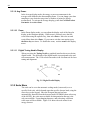
1
Model 842-PE
Hand-held Optical Power/Energy Meter
User’s Manual
1
Warranty
Newport Corporation warrants that this product will be free from defects in
material and workmanship and will comply with Newport’s published
specifications at the time of sale for a period of one year from date of
shipment. If found to be defective during the warranty period, the product
will either be repaired or replaced at Newport's option.
To exercise this warranty, write or call your local Newport office or
representative, or contact Newport headquarters in Irvine, California. You
will be given prompt assistance and return instructions. Send the product,
freight prepaid, to the indicated service facility. Repairs will be made and the
instrument returned freight prepaid. Repaired products are warranted for the
remainder of the original warranty period or 90 days, whichever is longer.
Limitation of Warranty
The above warranties do not apply to products which have been repaired or
modified without Newport’s written approval, or products subjected to
unusual physical, thermal or electrical stress, improper installation, misuse,
abuse, accident or negligence in use, storage, transportation or handling. This
warranty also does not apply to fuses, batteries, or damage from battery
leakage.
THIS WARRANTY IS IN LIEU OF ALL OTHER WARRANTIES,
EXPRESSED OR IMPLIED, INCLUDING ANY IMPLIED WARRANTY
OF MERCHANTABILITY OR FITNESS FOR A PARTICULAR USE.
NEWPORT CORPORATION SHALL NOT BE LIABLE FOR ANY
INDIRECT, SPECIAL, OR CONSEQUENTIAL DAMAGES RESULTING
FROM THE PURCHASE OR USE OF ITS PRODUCTS.
First printing 2007
© 2004 by Newport Corporation, Irvine, CA. All rights reserved. No part of
this manual may be reproduced or copied without the prior written approval
of Newport Corporation.
This manual has been provided for information only and product
specifications are subject to change without notice. Any change will be
reflected in future printings.
Newport Corporation
1791 Deere Avenue
Irvine, CA, 92606
USA
P/N: 90001049
D/N: 45501 REV B
2
Declaration of Conformity
We declare that the accompanying product, identified with the
mark, complies with
requirements of the Electromagnetic Compatibility Directive, 200489/108336/EEC and the
Low Voltage Directive 73/23/EEC.
Model Number: 842-PE Power Meter
Year
mark affixed: 2007
Type of Equipment: Electrical equipment for measurement, control and laboratory use
Manufacturer: Newport Corporation
1791 Deere Avenue
Irvine, California 92606
Standards Applied:
Compliance was demonstrated to the following standards to the extent applicable:
BS EN61326-1: 1997+A1+A2 +A3 “Electrical equipment for measurement, control and
laboratory use – EMC requirements”
This equipment meets the CISPR 11:2006+A2 Class A Group 1 radiated and conducted
emission limits.
BS EN 61000-3-2:2001, Harmonic current emissions, Class A
BS EN 61000-3-3:2002, Voltage fluctuations and flicker
BS EN 61010-1:2001, 2nd Edition “Safety requirements for electrical equipment for
measurement, control and laboratory use”
Bruno Rety
Group Director of PPT Instrument and Motion Europe
Zone Industrielle
45340 Beaune-la-Rolande, France
Dan Dunahay
Director of Quality Systems
1791 Deere Avenue
Irvine, Ca. USA
3
Technical Support Contacts
North America & Asia
Europe
Newport Corporation Service Dept.
Newport/MICRO-CONTROLE S.A.
1791 Deere Ave. Irvine, CA 92606
Zone Industrielle
Telephone: (949) 253-1694
45340 Beaune la Rolande, FRANCE
Telephone: (800) 222-6440 x31694
Telephone: (33) 02 38 40 51 56
Asia
Newport Opto-Electronics
Technologies
253 Aidu Road, Bld #3, Flr 3, Sec C,
Shanghai 200131, China
Telephone: +86-21-5046 2300
Fax: +86-21-5046 2323
Newport Corporation Calling Procedure
If there are any defects in material or workmanship or a failure to meet
specifications, promptly notify Newport's Returns Department by calling
1-800-222-6440 or by visiting our website at www.newport.com/returns within the
warranty period to obtain a Return Material Authorization Number (RMA#).
Return the product to Newport Corporation, freight prepaid, clearly marked with the
RMA# and we will either repair or replace it at our discretion. Newport is not
responsible for damage occurring in transit and is not obligated to accept products
returned without an RMA#.
E-mail: [email protected]
When calling Newport Corporation, please provide the customer care representative
with the following information:
•
•
•
Your Contact Information
Serial number or original order number
Description of problem (i.e., hardware or software)
To help our Technical Support Representatives diagnose your problem, please note
the following conditions:
•
•
•
•
Is the system used for manufacturing or research and development?
•
Can you identify anything that was different before this problem occurred?
What was the state of the system right before the problem?
Have you seen this problem before? If so, how often?
Can the system continue to operate with this problem? Or is the system nonoperational?
4
Safety Information
Do not use the 842-PE if the instrument or the detector looks damaged, or if
you suspect that the 842-PE is not operating properly.
Appropriate installation must be done for water-cooled and fan-cooled
detectors. Refer to the specific instructions for more information. The user
must wait for a while before handling these detectors after power is applied.
Surfaces of the detectors get very hot and there is a risk of injury if they are
not allowed to cool down.
Note: This equipment has been tested and found to comply with the limits for
a Class B digital device, pursuant to part 15 of the FCC Rules. These limits
are designed to provide reasonable protection against harmful interference in
a residential installation. This equipment generates, uses, and can radiate
radio frequency energy and, if not installed and used in accordance with the
instructions, may cause harmful interference to radio communications.
However, there is no guarantee that interference will not occur in a particular
installation. If this equipment does cause harmful interference to radio or
television reception, which can be determined by turning the equipment off
and on, it is suggested to try to correct the interference by taking one or more
of the following steps:
•
•
•
•
Reorient or relocate the receiving antenna.
Increase the distance between the equipment and receiver.
Connect the equipment to an outlet that is on a different circuit than the
receiver.
Consult the dealer or an experienced radio/TV technician for help.
SYMBOLS
The following international symbols are used in this manual:
Refer to the manual for specific Warning or Caution information to avoid any
damage to the product.
DC, Direct Current
5
Table of Contents
Warranty
1
Declaration of Conformity
2
Technical Support Contacts
3
Safety Information
4
List of Illustrations
10
1 General Information
11
1.1
1.2
1.3
1.4
1.5
1.6
Introduction .................................................................................11
Unpacking....................................................................................12
Parts List......................................................................................12
General Specifications.................................................................12
Front Panel Description...............................................................15
1.5.1 I/O and Backlight Control Key........................................15
1.5.2 ←, ↑, →, ↓ Arrow Keys..................................................15
1.5.3 ENTER Key.....................................................................16
1.5.4 Menu Key ........................................................................16
1.5.5 LCD Screen .....................................................................16
1.5.6 Shift Key..........................................................................16
Top Panel Description .................................................................16
2 System Operation
2.1
2.2
2.3
19
Accessing the Menu Structure.....................................................19
Making a Measurement ...............................................................21
Top Level Menu Structure...........................................................23
2.3.1 Display Menu ..................................................................24
2.3.1.1 Real Time Display .................................................24
2.3.1.2 Histogram Display .................................................25
2.3.1.3 Line Plot Display ...................................................25
2.3.1.4 Statistics Display....................................................26
2.3.1.5 Peak Power Display ...............................................26
2.3.1.6 Status Display ........................................................27
6
2.3.1.7 View File................................................................27
2.3.1.8 Fluence...................................................................27
2.3.1.9 Avg Power. ............................................................28
2.3.1.10 Zoom ......................................................................28
2.3.1.11 Digital Tuning Needle Display ..............................28
2.3.2 Scale Menu ......................................................................28
2.3.3 Settings Menu..................................................................29
2.3.3.1 Wavelength Setting................................................30
2.3.3.2 Corrections Setting ................................................30
2.3.3.3 Data Sampling Settings..........................................32
2.3.3.4 Period Multiplier....................................................37
2.3.3.5 Trig Level Setting ..................................................37
2.3.3.6 Reference Values ...................................................38
2.3.3.7 Save and Load User Settings .................................39
2.3.3.8 Power Unit .............................................................39
2.3.3.9 Communication......................................................39
2.3.3.10 Fluence...................................................................40
2.3.3.11 Peak Power.............................................................40
2.3.4 Control Menu...................................................................40
2.3.4.1 Zero Offset .............................................................40
2.3.4.2 Acquire Data ..........................................................41
2.3.4.3 Transfer File...........................................................41
2.3.4.4 Statistics Mode.......................................................42
2.3.4.5 Relative Mode........................................................42
2.3.4.6 Energy Mode..........................................................43
2.3.4.7 Analog OUT...........................................................43
2.3.4.8 Anticipation ...........................................................44
2.3.4.9 Display Hi Res .......................................................44
2.3.4.10 View Data ..............................................................44
2.3.4.11 Attenuator ..............................................................44
2.3.4.12 Set Diode Zero .......................................................45
2.3.5 “?”....................................................................................45
3 Computer Interfacing
3.1
3.2
46
Installation ...................................................................................46
Setup ............................................................................................47
3.2.1 COM Port Verification ....................................................47
3.2.2 Establishing Communication...........................................47
7
3.3
3.2.3 HyperTerminal Settings Shortcut ....................................48
Software.......................................................................................48
4 Command Reference
4.1
4.2
49
Commands and Queries...............................................................49
4.1.1 Command Format ............................................................49
4.1.2 Command Directory ........................................................51
Serial commands .........................................................................52
4.2.1 Display Commands .........................................................52
4.2.1.1 Set Display .............................................................52
4.2.1.2 Set Scale.................................................................52
4.2.1.3 Set dBm Display ....................................................53
4.2.1.4 Set High Resolution Display..................................54
4.2.2 Measurement Commands -- Data Acquisition ..............54
4.2.2.1 Query Current Value..............................................54
4.2.2.2 Query New Value Ready .......................................54
4.2.2.3 Query Statistics Data .............................................55
4.2.2.4 Set Logging Start/Stop...........................................55
4.2.2.5 File Download........................................................55
4.2.2.6 Download data .......................................................56
4.2.3 Measurement Commands -- Setup ................................56
4.2.3.1 Set Wavelength Correction ....................................56
4.2.3.2 Set Attenuator ........................................................57
4.2.3.3 Set Multipliers........................................................57
4.2.3.4 Set Offsets..............................................................57
4.2.3.5 Query Data Sampling Settings...............................58
4.2.3.6 Configure Data Sampling ......................................58
4.2.3.7 Set Trigger Level ...................................................59
4.2.4 Measurement Commands -- Control .............................59
4.2.4.1 Enable Statistics.....................................................60
4.2.4.2 Set Energy Mode ...................................................60
4.2.4.3 Set Anticipation .....................................................60
4.2.4.4 Set Zero Offset.......................................................60
4.2.5 Instrument and Detector Information Commands ...........60
4.2.5.1 Query Version........................................................61
4.2.5.2 Query Detector Head Name...................................61
4.2.5.3 Query Status...........................................................61
4.2.5.4 Query Battery Power .............................................63
8
4.2.5.5 Set Internal Clock ..................................................63
4.2.6 Instrument Control Commands .......................................63
4.2.6.1 Set Backlight..........................................................63
4.2.6.2 Set Analog Output .................................................64
4.2.7 Communications Commands...........................................64
4.2.7.1 Test Communication..............................................64
4.2.7.2 Init Serial Port........................................................64
5 Error Messages
65
6 Maintenance
66
6.1
6.2
6.3
USB installation for the 842-PE ..................................................66
Free Software and Firmware Upgrades.......................................66
Battery Charging .........................................................................66
7 Service Information
7.1
7.2
7.3
68
Service Form ...............................................................................69
Introduction ............................................................................71
Procedure 71
Binary Mode Rules......................................................................73
Conversion of Values Transferred with Binary Commands...74
Binary Command Reference .......................................................74
Set Display..............................................................................74
Set Scale 75
Set dBm Display .....................................................................76
Set High Resolution Display ..................................................76
Query Current Value...............................................................76
Query New Value Ready ........................................................77
Query Statistic Data................................................................77
Set Logging Start/Stop............................................................78
File Download ........................................................................78
Set Wavelength Correction.....................................................78
Set Attenuator .........................................................................78
Set Multipliers ........................................................................79
Set Offsets...............................................................................79
Query Data Sampling Settings................................................79
Configure Data Sampling .......................................................80
Set Trigger Level ....................................................................80
9
Enable Statistics......................................................................81
Set Energy Mode ....................................................................81
Set Anticipation ......................................................................81
Set Zero Offset........................................................................81
Query Version.........................................................................81
Query Detector Head Name....................................................82
Query Status............................................................................82
Query Battery Power ..............................................................84
Set Internal Clock ...................................................................84
Set Backlight...........................................................................84
Set Analog Output ..................................................................84
Test Communication...............................................................84
Init Serial Port.........................................................................84
Appendix A
85
Recycling and separation procedure. ....................................................85
Separation: ............................................................................................85
Dismantling procedure:.........................................................................86
10
List of Illustrations
Fig. 1-1 842-PE Front Panel ......................................................................... 15
Fig. 1-2 842-PE Top Panel ........................................................................... 16
Fig. 2-1 The Menu Bar ................................................................................. 20
Fig. 2-2 The Dialog Box............................................................................... 21
Fig. 2-3 View of the first group of 842-PE menus ....................................... 24
Fig. 2-4 Real Time Display .......................................................................... 25
Fig. 2-5 Display Options Menu .................................................................... 25
Fig. 2-6 Statistics Display............................................................................. 26
Fig. 2-7 Status display .................................................................................. 27
Fig. 2-8 View File screen ............................................................................. 27
Fig. 2-9 Digital Needle Display.................................................................... 28
Fig. 2-10 Scale menu .................................................................................... 29
Fig. 2-11 Settings menu................................................................................ 30
Fig. 2.12 Settings/Corrections menu ............................................................ 31
Fig. 2-13 Data sampling parameters window ............................................... 34
Fig. 2-14 Pass/Fail menu .............................................................................. 38
Fig. 2-15 Pulse Width setting for the Peak Power mode.............................. 40
Fig. 2-16 View of the Ctrl Menu Structure .................................................. 41
11
1 General Information
1.1 Introduction
To obtain the full performance from the 842-PE, we recommend that you
read this manual carefully.
The 842-PE hand-held optical meter is a microprocessor-based power and
energy meter that uses the latest technology to provide a multitude of options
in a user-friendly environment. It is a complete power and energy meter,
providing the user with everything from statistical analyses to data logging.
It allows the user to store up to 50,000 data points in its internal memory.
When a detector is connected to the instrument, its specific model type and
calibration information is downloaded into the meter, enabling the
appropriate measurement ranges and units of measure. When connecting a
818E-xx-xx-F fast energy dectector, the 842-PE enters into the metallic mode
to ensure proper measurements. The 842-PE also has improved
performance in joulemeter mode that enables 2 additional lower measurement
scales.
The 842-PE firmware can be updated over the internet by connecting the
USB or the RS-232 port to a personal computer. The instrument’s enhanced
network capabilities take further advantage of the USB and RS-232 ports for
data acquisition and remote control. It can transfer data files to a PC for more
sophisticated data analysis and respond to commands through the PC
interface. The CD included with this meter contains LabVIEW drivers that
will transform your PC screen into a virtual 842-PE. While having a copy of
LabVIEW installed on your PC is required in order to use this CD, LabVIEW
is not needed for programming the instrument in general. See Section 3 for
communication with a computer.
Easy software and firmware upgrades
Keep in touch with the latest improvements to our user-friendly software.
You can download the latest software and firmware versions anytime from
our website www.newport.com and install it on the 842-PE with the serial
interface. You will find all the necessary information on downloading and
upgrading in Section 6.2.
12
1.2 Unpacking
Each Newport 842-PE hand-held optical meter is thoroughly tested and
calibrated prior to shipment.
Visually inspect your 842-PE after removing it from the shipping container.
If you see any damage, retain all packaging materials and shipping receipts.
Any damage claim should be made promptly to the transportation company.
Notify the nearest Newport representative concerning the claim, so that any
repair or replacement can be arranged as soon as possible.
1.3 Parts List
The following is a list of parts included with the 842-PE Handheld Power
Meter. Please make sure everything is present before discarding packing
materials.
•
•
•
•
•
•
•
1.4
842-PE hand-held meter
842-BAT battery pack (installed in 842-PE)
Power supply / battery charger
USB cable
Software (CD)
User Manual (CD)
Start-Up Guide
General Specifications
The following specifications are based on a one-year calibration cycle, an
operating temperature of 18ºC to 28ºC (64ºF to 82ºF) and a relative humidity
not exceeding 80%.
General Specifications 842-PE
Digital Display
Display Rate
76.78 x 57.58 mm LCD, 240 x 160 Pixels
3 Hz numeric display
15 Hz bar graph & needle display
Bar Graph
Data Displays
User input correction factors
Analog Output
Computer Interfaces
1
165 divisions
Real time, Line plot, Histogram, Statistics, Digital tuning needle
2 multipliers and 2 offsets (7 digits floating point)
0 – 1 volt, full scale, ± 1%
USB and RS-232 1
USB cable included. RS-232 cable sold separately (part number 842-CAB).
13
High throughput serial
frequency
Up to 200Hz, with a 310 ms delay between burst for Metalic or XLE
joulemeters, whereas 45 to 78 ms for MB joulemeter and power heads..
Dimensions (without stand)
230mm (W) x 122mm (H) x 44 mm (D)
Weight (with stand)
0.52 kg
Battery Pack
4 rechargeable 1.2 V Ni-MH AA
Battery Life
11 hours, 6 hours with backlight
Battery Charge Time
Universal Power Supply
6 hours
Input: 100/240 VAC 50-60 Hz, Output 9 VDC 1.66 A
14
Power Meter Specifications
1 nW to 10 kW
Power Range
Low Power Scales
(with 918D and 818-Series detectors)
10nW, 30nW, 100nW, 300nW, 1µW, 3µW, 10µW,
30µW, 100µW, 300µW, 1mW, 3mW, 10mW, 30mW,
100mW, 300mW, 1W, 3W
30mW, 100mW, 300mW, 1W, 3W, 10W, 30W, 100W,
300W, 1kW, 3kW, 10kW
High Power Scales
(with 818P Series detectors)
Resolution (digital)
5 µW on the 30 mW scale
Meter Accuracy
±0.5 % ±5 µV full scale 2
Response Time (accelerated) 3
1 sec
200 kHz
Sampling Frequency
Statistics
Current value, Max, Min, Average, Std Dev., RMS
stability, PTP stability, Time
Energy Meter Specifications
Energy Range
1µJ to 20 kJ
Energy Scales
100µJ, 300µJ, 1mJ, 3mJ, 10mJ, 30mJ, 100mJ, 300mJ, 1J, 3J, 10J, 30J, 100J,
300J, 1kJ, 3kJ, 10kJ, 30kJ
Resolution (digital)
Accuracy 4
50 nJ
1.0 %±50 µV < 500 Hz
2.0 %±50 µV 500 Hz to 1.2 kHz
3%±50 µV 1.2 kHz to 6 kHz (MT mode)
6%±50 µV 6kHz to 10 kHz (MT mode)
Default Trigger Level
Software Trigger Level
2%
0.1% to 99.9%, 0.1% resolution
Metallic mode : hardware set to 3%.
Repetition Frequency
3 kHz in acquire data, no missing point
2 kHz in statistics mode, no missing point
3-10 kHz in acquire data, ignores all laser pulses for 333us after laser pulse
detection.
Statistics
Data Storage
2
Current value, Max, Min, Average, Std Dev., RMS stability, PTP stability, Pulse
#, Repetition Rate, Avg Power
50,000 points 5
The 5µV bias can introduce an error into low power measurements when using the 818-series Low Power
Detectors. It is essential to use the Zero Offset to rezero the 842-PE before making a measurement in these
conditions. It is always good practice to use the Zero Offset. See section 2.2.
3
Varies with individual detector (see 818P Series Detector Manual).
4
Including linearity.
5
Up to 225,000 if not using any advanced features that require memory.
15
Fig. 1-1 842-PE Front Panel
1.5 Front Panel Description
1.5.1 I/O and Backlight Control Key
The I/O key has two functions:
842-PE on and off
Pressing the I/O key quickly when the 842-PE is OFF turns the 842-PE ON
(do not hold the I/O key). To turn off the 842-PE, press and hold the I/O key
a few seconds. To prevent battery leakage and to increase battery life, we
recommend turning off the 842-PE when not in use.
Backlight control
With the 842-PE ON, pressing the I/O key very quickly switches the LCD
screen Backlight ON or OFF. If you are working without the external
power supply, turn the backlight off for longer battery life.
1.5.2 ←, ↑, →, ↓ Arrow Keys
The Arrow keys allow the user to browse through the menus. Press the
Right Arrow key until you reach your desired option. To go backwards,
press the Left Arrow key.
When you are not in the Menu, the Arrow keys function as quick access keys:
UP and Down keys: Increase or decrease the scale selection after correction
factor has been entered (Note: entering a correction factor disables the auto
scale).
Left key: Set or reset a zero offset.
Right key: Activate the custom wavelength keypad.
16
1.5.3 ENTER Key
The ENTER key selects the highlighted option.
1.5.4 Menu Key
The Menu key gives access to the MENU BAR.
1.5.5 LCD Screen
76.8 x 57.6 mm Liquid Crystal Display Screen, 160 X 240 pixels.
Press the shift key and use the Up and Down arrow keys (↑ ↓) to decrease
and increase the LCD screen contrast.
1.5.6 Shift Key
The Shift key provides access to additional quick access keys:.
Shift-key right : activate the attenuator for photodiode heads.
Shift-key left : open the data sampling settings menu.
Shift-key up: decrease the contrast level.
Shift-key down: increase the contrast level.
Shift-key menu: open the statistic menu.
1.6 Top Panel Description
Fig. 1-2 842-PE Top Panel
1 EXTERNAL POWER SUPPLY INPUT JACK:
The input jack is for connecting the AC wall-plug power supply provided with the
instrument. battery charger supplied with the instrument. When using the power
supply, the internal battery pack is also being charged, for use of the instrument
without the power supply. Input voltage required: 9 VDC/800 mA.
CAUTION
Permanent damage may occur to the optical meter if an external
17
power supply other than the Newport PM-PS9 (200960A) is used.
Please call Newport Corporation if extra power supplies are
needed for a particular setup.
2 SERIAL INTERFACE CONNECTOR (RS-232):
This interface allows remote control and data transfer between the 842-PE
and a computer, a terminal, a printer or any device that has a serial
communication port.
3 USB INTERFACE CONNECTOR:
This interface allows remote control and data transfer between the 842-PE
and a computer that has a USB communication port.
4 0 to 1 VOLT ANALOG OUTPUT:
For monitoring laser average power or energy by using external equipment
such as a chart recorder, a computer with an analog interface, a voltmeter,
etc.
In the case of a power measurement, the output signal represents the
amplified and anticipated power detector response.. In the case of an energy
measurement, the output signal is a DC voltage representing the pulse energy
value.
The 1 V value corresponds to the full scale reading of the selected range.
This will provide the best signal-to-noise ratio. The measured power or
energy is then related to the output voltage and to the selected range in this
manner:
Power = Voutput × Max of Range selected
Energy = Voutput × Max of Range selected
For example:
1.00 V corresponds to 10 Watt on the 10 W range
0.25 V corresponds to 2.5 Watt on the 10 W range
0.10 V corresponds to 30 milliwatts on the 300 mW range
Specifications:
Maximum output voltage:
1V
Output impedance:
10 kΩ
Connector type:
Female 1/8” jack
18
5 PROBE INPUT JACK:
The 842-PE uses a DB15 female connector to mate with compatible Newport
detectors. See section 2.2 for compatible detector list.
19
2 System Operation
This section contains important information concerning the installation and
operation of the 842-PE.
When delivered, the 842-PE just needs the battery pack installed and it is
ready foruse. Just insert a detector head in the Probe Input Jack (#5 in Figure
1-2) and press the I/O key. If the meter doesn’t turn on, the battery pack may
be drained. Please turn it off, plug in the charger and let it charge for several
hours before attempting to use again.
2.1 Accessing the Menu Structure
The powerful CPU of the 842-PE, combined with the Windows™ CE
operating system, provide easy and intuitive access to all of its functions.
This user-friendly Windows™-based interface is controlled by four Arrow
keys, an ↵ key (Enter key) and a Menu key . For users familiar with
Windows™, it works as any Windows™ menu, with the ALT key being
replaced by the F key.
Pressing the F key (see Figure 2-1) provides access at any time to the menu
bar and, from there, to the five main menus. Use the Left and Right arrow
keys to go from one menu to the next. The selected menu drops down to
show its options. Use the Up and Down arrow keys to select the desired item
from the menu. Once the desired item is highlighted, press the Enter “↵” key
to activate the function. When a menu option has an arrow “X” at the end,
pressing Enter “↵” or the Right Arrow key “t”opens a submenu where you
can select the function. For example, in the case of the Setting menu, first
select Corrections with the Down Arrow key, followed by the Enter “↵” or
the Right Arrow key “t” to access the submenu. Move to the desired
option with the arrow keys and press the Enter “↵” key to activate.
20
Display
Scale
Settings
Ctrl
Wavelength
Settings
Review
Corrections
None
Data Sampling
Multiplier#1
(0.1200000)
Period Multiplier
Offset #1
Trig Level (2%)
Multiplier #2
Refer Values
Offset #2
Fig. 2-1 The Menu Bar
Some menu options require additional information to be activated properly.
In this case, a dialog box (see Figure 2-2) appears. There you enter the
setting values of your choice. Use the Arrow keys to highlight a number and
press the Enter “↵” key to select it. The selected number will appear in the
upper box. Repeat the operation until the desired number has been fully
entered. Then go to “OK” and press Enter “↵” to validate your number.
You can correct a mistake by selecting the Back button (←) located in the
bottom right of the dialog menu. Use the Decimal button (.) to enter
decimals. The Percent button (%) gives you the flexibility to enter a value
as a percent rather than a fraction. For example, you can enter the same
multiplier as 0.925 or 92.5%.
?
21
Sensitivity (V/J)
200.00
7
8
9
OK
4
5
6
%
1
2
3
+/-
0
.
←
X
Fig. 2-2 The Dialog Box
2.2 Making a Measurement
This section will show you the fastest way of making a laser power and
energy measurement with the 842-PE and a Newport power or energy
detector.
The 842-PE Handheld Power and Energy Meter automatically recognizes all
Newport low-power, high-power and energy detectors terminated with a15pin connector. All calibration and technical data required for optimum
operation of the detector will be automatically downloaded from the
EEPROM in the DB15 connector. This data includes sensitivity, model,
serial number, version, wavelength correction factors, and time response.
Quick power and energy measurement procedure:
1- Install the power or energy detector head on its optical stand.
2- Turn the 842-PE off and connect a compatible power or energy detector
(see Table 1-2 below) to the 842-PE using the PROBE INPUT JACK
(see Fig. 1-2). It is necessary to turn the 842-PE off before connecting a
new detector in order to prevent any loss of information from the detector
EEPROM and to read the detector EEPROM..
Detectors compatible with 842-PE Power and Energy Meter
818P Series High Power Detectors
818E Series Energy Detectors
918D Series Low Power Detectors
818 Series Low Power Detectors (with connector adapter)
Table 1-2. Detectors compatible with the 842-PE
22
3- Fasten the DB-15 thumbscrews.
4- Switch the 842-PE ON using the I/O key.
5- When using an 818-Series Low Power or 818P-Series High Power
detectors, the 842-PE will default into power measurement mode. When
using 818E-Series Energy detectors, it will default into energy
measurement mode. The meter will also default to autoscale. If you are
using an 818-Series Low Power detector, to obtain measurements in
dBm, select Settings / Power Unit / dBm.
6- Remove the detector’s protective cover and put the detector head into the
laser beam path. Leave it there for a few minutes, until the detector has
reached an equilibrium temperature. The entire laser beam must be
within the sensor aperture. Do not exceed maximum specified power or
energy densities. For the most accurate measurement, spread the beam
across 60% to 80% of the sensor area.
NOTE:
Power detectors can be used with both CW and pulsed lasers.
Energy detectors can only be used with pulsed lasers.
Zero Offset Adjustment (steps 7 and 8). If using an 818P Series High
Power Detector, proceed with step 7. If using a 918D Series or 818 Series
Low Power Detector, go to step9. For 818E Series Energy Detectors,
jump to step 11.
7- Block off laser radiation to the detector.
The power read by the 842-PE when no laser beam is incident on the
detector may not be exactly zero. This is due to the fact that the detector
is not thermally stabilized OR there is a heat source in the field of view
of the detector when you turned on the 842-PE.
8- To reset the zero, wait until the reading has stabilized and select Zero
Offset in the Ctrl (Control) menu. Then select Rezero. You are now
ready to make an accurate measurement. To turn the Zero Offset off,
select Off, to reselect the previous offset, select Undo.
Low Power Detector Zeroing:
9- To set a Low Power Detector to zero, select Ctrl / Set Diode Zero, and
press the ↵ Enter key. A message appears requesting that you put the
cover on your photodiode and then press the ↵ Enter key. The 842-PE
passes through all the scales to determine the zero diode for each scale.
The message “Diode Zero Done” appears when the 842-PE has
determined the zero diode.
23
Notes:
•
Refer to specific power detector documentation for complete
installation and operating instructions.
• The 818P-series High Power Detectors are thermal sensors that are
sensitive to temperature variations.
For high-precision measurements, it is recommended to:
• Allow the power detector temperature to stabilize before zeroing
the 842-PE.
• Do not touch the detector head when handling the power detector.
Touch only the stand.
• Avoid forced airflow or air drafts around the detector.
10- Apply the laser beam to the detector head.
11- The laser beam average power or energy will be displayed in three ways
for your convenience (see section 2.3.1):
a. Digitally for real time measurement.
b. On a digital needle for an easy visualization of the laser beam
power variation during laser fine-tuning.
c. On a histogram to allow the laser beam’s long-term stability to be
evaluated.
2.3 Top Level Menu Structure
This section describes in detail the first group of menus essential to the 842PE operation. Refer to Figure 2-3 for a schematic view of the menu
structure. The menus differ depending on the type of detector that is
currently being used. The Display menu lets you view your measurement in
various ways. The Scale menu allows you to fix a specific measurement scale
instead of autoscaling. Use the Settings menu during setup to select the best
parameters for the measurement task at hand. These menus provide the
flexibility needed to accommodate a wide variety of measurement conditions.
The more active controls you are likely to use during your measurements are
in the Ctrl menu. They are described in Section 2.3.4.
24
Display
Scale
Settings
Ctrl
√ Real Time
View File
Auto
Wavelength
Save Settings
Histogram
Fluence
Zoom In
Corrections
Load Settings
Line Plot
Avg Power
Zoom Out
Data Sampling
Power Unit
Statistics
Zoom…
Period Multiplier
Communication
Peak Power
Tuning Needle
Trig Level (2.0%)
Fluence
Refer Values
Peak Power
Scale
Status
Fig. 2-3 View of the first group of 842-PE menus
2.3.1 Display Menu
The various displays offered by the 842-PE allow you to quickly view your
measurement in several different ways. You will appreciate the easy-to-view
high resolution 58 x 38 mm graphic, the LCD display and the backlight for
use in poor ambient light conditions. The Display menu includes five
options, (see Figure 2-3) that allow you to select the best way to display the
measurement according to your specific needs. You can switch from one
option to another without interfering with the measurements.
2.3.1.1 Real Time Display
This display is automatically selected when a detector is connected to the
842-PE. The top and bottom of the screen show important settings so you
can see the conditions as well as the measurement (see Figure 2-4). The
Power or Energy digital display is presented in giant format for easy reading
in all conditions. Directly below, the Bar Graph display, as wide as the
screen, presents the measurement in an analog format, very useful for rapidly
varying values. Displayed on the upper left part of the screen is the Detector
Model. Under the Bar Graph is the current Scale. At the bottom of the
screen the leftmost box contains the actual power or energy received by the
head before any correction factors are applied. The center box gives the
resolution and the rightmost box displays the wavelength. The resolution is
the smallest increment that the current value may change on a given scale.
The wavelength value tells you what NIST-based calibration factor is
currently being used. You can find the factors on the Calibration Report (for
Low Power Detectors) or the Personal Wavelength Correction™ certificates
(for High Power and Energy Detectors) that are shipped with your detector.
?
25
Display
Scale
Settings
Ctrl
?
818P-015-19
15.20 mW
0.00
Head:15.20 mW
30.0 mW
Res:14.65 μW
@ 1064 nm
Fig. 2-4 Real Time Display
With an 842-PE, you can also choose either the high resolution mode for the
most significant digits available, or the standard resolution to filter out
unimportant fluctuations in measurement. This is a setting in the control
(Ctrl) menu of the 842-PE.
2.3.1.2 Histogram Display
The histogram option gives a quick look at the laser beam’s long-term stability and trends. The
histogram adds new data points at a rate of 3 Hz and is dynamically scrolled to the left for each
new point as soon as it reaches the right side of the screen.
Display
Scale
Real Time
View File
√ Histogram
Fluence
Line Plot
Avg Power
Statistics
Zoom…
Peak Power
Tuning Needle
Settings
Ctrl
?
Status
Fig. 2-5 Display Options Menu
2.3.1.3 Line Plot Display
The line plot also shows the trends in your data. Actual values are sometimes
easier to read than with the Histogram.
26
2.3.1.4 Statistics Display
In Statistics display mode, the statistical analysis screen pops-up on top of the
Main display. This screen (Figure 2-6) gives a complete statistical analysis
of the measured data. See Section 2.3.3.3 for a detailed description of each
parameter. Select the Start button to start or restart the data sampling and
statistical calculations. Use the Stop button to stop the data sampling and
statistics before you reach the end of the selected sampling time. The last
statistical values calculated remain on screen so you can view them later,
even if you close and reopen the Statistics window. To set the data to zero,
select Reset. To restart the data sampling, select Start. The Close button
closes the statistics window so you can see the Main display again but does
not interfere with the statistics being computed. The data sampling and
statistical calculations continue with this window closed or open, and are
independent of the display you select. You can open and close the statistics
display window to check on the statistics as often as you like.
The values in this display provide an additional digit of resolution to allow
you to benefit from the improved precision of large samples. You must
understand your sample size well enough to know if this additional digit is
significant.
Statistics
Current Value:
0.9512 W
Close
Maximum Value: 0.9519 W
Start
Minimum Value: 0.9505 W
Stop
Average Value:
0.95118 W
Reset
Std deviation:
RMS Stability:
PTP Stability:
Time:
0.9135 mW
0.096 %
0.147 %
4/10 Sec
Cancel
period
Fig. 2-6 Statistics Display
2.3.1.5 Peak Power Display
In the Peak Power display mode, the pulse energy measurement of the energy
mode is converted to its peak power (Watts) and is inversely proportional to
the pulse length. This function is active only in energy mode. The user must
enter the pulse width, from picoseconds to milliseconds units using
Setting/Peak Power in the Settings menu.
27
2.3.1.6 Status Display
The Status Display mode shows all the major adjustable parameters currently
active for the detector head in one convenient place (see Figure 2-8).
Fig. 2-7 Status display
2.3.1.7 View File
The View File mode allows you to view data previously acquired. Choose
between standard (Std) notation and scientific (Sci) notation.
Fig. 2-8 View File screen
2.3.1.8 Fluence
In the Fluence display mode, the energy or power measurement is converted
into energy density (J/cm2) or into power density (Watts/cm2) and is inversely
proportional to the surface area of the beam. This function is active only in
the energy and power modes. The user must enter the beam size, see
Settings/Fluence in the Settings menu.
28
2.3.1.9 Avg Power.
In the Average display mode, the energy or power measurement is the
average value defined in the data sampling menu. You can change your data
sampling to your desired average time or number of points for Energy
measurement. To activate the average display go into the Ctrl Menu select
Stat mode then select Start.
.
2.3.1.10
Zoom
In the Zoom display mode, you can adjust the display scale of the line plot
display or the histogram display. When zoom is selected, move the first
vertical line using the up/down key, then select Enter. Move the second
vertical lines then select Enter. If you want to exit the zoom option, press
the Enter key two times. To disable the zoom, reselect zoom in the display
menu.
2.3.1.11
Digital Tuning Needle Display
When you select the Tuning Needle, a graphical interface shows a real-time
digital needle. The deflection of the digital needle is proportional to the realtime measurement. The 15 Hz refresh rate makes it an excellent tool for laser
tuning and alignment.
Fig. 2-9 Digital Needle Display
2.3.2 Scale Menu
The scale can be set to the automatic scaling mode (Auto mode) or to a
specific fixed scale, which depends upon the specific detector head, using the
arrow keys on the keypad. Once the Newport detector has been
automatically identified from the detector head’s EEPROM (done at boot-up
of the 842-PE), the scale menu available for that particular detector is the
only one available. Upon changing detectors, and re-booting, a different
scale menu will be available. Figure 2-10 shows the scale menu for an
energy detector.
29
Display
Settings
Ctrl
?
√ Auto
100 mJ
300J
300 mJ
1 kJ
1 mJ
3 mJ
3J
10 kJ
10 mJ
10 J
30 kJ
30 mJ
30 J
100 J
100 µJ
300 µJ
Fig. 2-10 Scale menu
The Scale Menu is used to select the signal level read with a detector head.
When a new detector is connected, the autoscale is the default option. In this
condition the 842-PE automatically selects the best scale for the value being
measured.
The checkmark beside the scale number shows the currently selected scale.
To change the scale, simply select a scale value from the appropriate range.
The 842-PE only shows scale values that fall within the detector head’s
range.
When in a manually selected scale, you should always use the next higher
scale to the measured value, for maximum precision.
Special care must be taken in the case of widely varying pulse energy to
ensure that every pulse is detected. Contrary to the case of a power
measurement where the autoscale adjusts continuously to the measured value,
the autoscale in energy mode bases its scale selection on the energy of the
previous pulse. A pulse with energy less than 2% of the energy of the
previous pulse will not be detected. To avoid this problem, set the scale
manually to a lower level. In this case, you measure this lower level when
the higher energy pulses are saturated.
2.3.3 Settings Menu
Options in the Settings menu define user-adjustable acquisition parameters.
All correction factors that will affect the reading can be easily programmed.
That could be for a beam sampler, attenuator, or other optics that require you
to multiply and/or add offsets to the detector reading. You can also adjust for
a wavelength other than the calibration wavelength. A custom correction
30
factor can also be keyed in. Pre-programmed wavelength correction factors
dedicated to each detector head are also available and automatically loaded
from the detector EEPROM. Data Sampling and Trigger Level, as well as
the commands for saving and loading your settings are also found in the
Settings menu.
Display
Scale
Settings
Ctrl
Wavelength
Save Settings
Corrections
Load Settings
?
Data Sampling
Power Unit
Period Multiplier
Communication
Trig Level (2.0%)
Fluence
Refer Values
Peak Power
Fig. 2-11 Settings menu
2.3.3.1 Wavelength Setting
The Wavelength menu is used to select the proper wavelength for the
detector, based on the light input. It applies a correction to adjust for the
variation in responsivity at different wavelengths. When a new detector is
connected to the meter, and the meter has been re-booted, the calibration
wavelength is the default selection.
The checkmark beside the wavelength shows the current selection. To
change the wavelength, select an appropriate wavelength from the
Wavelength menu. The 842-PE only allows you to choose values that fall
within the detector’s range. If you select or enter a value that is not valid, an
error message appears and the 842-PE automatically selects the default value.
When working at a wavelength not available in the Wavelength menu, use
the custom option in that menu and enter the wavelength you need. The
wavelength you enter must be within the range of valid wavelengths for the
detector used. The 842-PE interpolates a wavelength correction factor using
the pre-programmed data in the detector’s EEPROM.
2.3.3.2 Corrections Setting
The user can apply up to 2 Multipliers (or Correction Factors) and 2 Offsets
to the detector reading. Correction factors are most useful when sampling a
percentage of a powerful laser beam or correcting for absorption along an
optical path. The menu displays the values of correction factors that are
being applied to the measurements. They may also be viewed in the Display
Status menu (see Figure 2-8).
31
Display
Scale
Settings
Ctrl
?
Wavelength
Corrections
None
Data Sampling
Multiplier #1
(0.1200000)
Trig Level
(2.0%)
Offset #1
Save Settings
Multiplier #2
Load Settings
Offset #2
Fig. 2.12 Settings/Corrections menu
To activate the correction factor, select Corrections in the Settings Menu
and then select Multiplier or Offset. A dialog box opens where you enter the
correction value in percentage or in absolute value. This number will then
multiply, or add, to the actual measured value to calculate the corrected
value. The 842-PE will then display the corrected value.
For example, if you are measuring a laser beam passing through the 99.9%
back reflector of a laser (giving 1/1000th of the real value), choose Multiplier
#1 and enter 1000 in the dialog box. The 842-PE will display the laser’s
actual power rather than the measured 0.1% sample on the main display.
The corrections are applied mathematically in the order shown in the menu.
Therefore, to apply an offset before a multiplier you would enter a value for
Offset #1 and a value for Multiplier #2 and leave Multiplier #1 at the default
value. The default value for the multipliers is 1, and the default for the
offsets is 0.
When a correction factor is active the “Head” value will be different from the
displayed measurement. The Head value is displayed at the bottom left of the
screen. The corrected measurement appears in the center of the screen (see
Figure 2-4).
It is also essential to make sure that the actual measured value complies with
the power and energy limits of the detector head. The Autoscale option is the
default selection. You can select a specific scale but it must always be based
on the actual physical measured value and not on the corrected values. Of
course, the displayed values and the display scale selection are then
calculated to take into account the correction factors.
32
Note that the Statistics are computed for the corrected values only.
To disable the correction factor, re-select the Correction Factor (multiplier,
offset) in the Corrections submenu of the Settings menu. Then select
None in that submenu.
2.3.3.3 Data Sampling Settings
The 842-PE can display a complete statistical analysis of power or energy
measurements. The Data Sampling menu is used to set up the data sampling
parameters for calculating the Statistics. You have complete control over the
data sampling. Use the defaults or select your own sample rate, sample
period, and the time period or number of points over which the statistics are
to be performed. The 842-PE can be set to either calculate the statistics for a
single sample and stop, or to repeat continuously. Data can be collected for a
few seconds or a few weeks. You have the flexibility to handle any
application, from analyzing a single short pulse with high resolution to
sampling performance over a period of months.
Selecting the Data Sampling mode in the Settings menu opens a Dialog
Box where you enter the sample rate, the sample period, total duration, and
the time stamp, if required.
The statistics being captured and calculated can be monitored by simply
selecting Statistics in the Display menu. You can switch back to any other
display mode without affecting the measurement or the statistics. You can
also click the Reset button in the display to clear all the statistical parameters
and start all over again by selecting the Start button. In order to have a good
frequency accuracy with the Metallic joulemeter types (818E-xx-xx-F), you
must at least make a 2 second statistical analysis. The statistical parameters
that are calculated are listed in Table 2.1.
Table 2.1. Statistical Parameters
Statistical Parameters
Power
Energy
Definition
Current value
√
√
Value of the most recent measurement
Maximum value
√
√
Highest value in the sample period, Emax or Pmax
Minimum value
√
√
Lowest value in the sample period, Emin or Pmin
Average value
√
√
Rolling average of values in the sample, Eavg or Pavg
Standard Deviation
√
√
A measure of the spread of the data around the average.
33
∑(E −E )
n
i
STD=
RMS stability
√
√
i=1
n−1
avg
∑(P−P )
n
2
i
, STD=
i=1
avg
2
n−1
Root mean square stability represents the standard
deviation as a percent of the average.
RMS = STD×100 , RMS = STD×100
Eavg
Pavg
PTP Stability
√
√
Shows the spread between the highest and lowest point
in the sample as a percent.
PTP =
Time
√
E max − E min
P − Pmin
× 100 , PTP = max
× 100
E avg
Pavg
Time elapsed since beginning the sample.
Pulse #
√
Number of the last pulse added to the sample.
Repetition Rate
√
Frequency of pulses coming from the laser, PRR
Average Power
√
Power calculated from the pulse energies and repetition
rate.
Pavg =Eavg×PRR
To Activate the Statistics, select Statistics from the Ctrl menu, and then
select Start in the submenu.
The 842-PE starts compiling statistics on your measurements as soon as the
Statistics mode is activated. Select Stop in the same submenu to turn the
Statistics mode off. When you stop the statistics, the last values remain in the
statistics display window for you to view later. If you click Start again, the
842-PE will resume the statistics from that point, compiling the new
measurements with the previous. Click Reset and all the statistical
parameters will be cleared and set to zero. If you click Reset without
stopping, all the statistical parameters will be cleared and the statistics will
begin from zero automatically.
Alternative: From the Display menu, select Statistics to enter the statistics
display window. The same commands are available there as buttons.
Selecting the Close button closes the window but does not turn off the
Statistics mode or interfere with the calculations. Selecting the Stop button
34
stops the calculation of new statistics but does not close the window so that
you can review the final values.
The 842-PE uses default sample parameters unless you set them yourself.
To View the Statistics, select Statistics from the Display menu.
To Set the Data Sample Parameters, select Data Sampling from the
Settings menu.
Figure 2-13 shows the window for setting the data sampling parameters. Use
the → RIGHT arrow key to move through the parameters and units windows.
Move to the one you want to set. Then use the ↑↓ UP and DOWN arrow
keys to change the value. If you want to enter a value that is not available
using the up and down arrow keys, then press the ↵ Enter key instead. The
keypad data entry dialogue box shown in Figure 2-2 will pop up to allow you
to enter a custom value. When you are finished, use the → RIGHT arrow
key to select the CLOSE box and press the ↵ Enter key. Table 2-2 defines
the various parameters.
The key points to remember whether using a High Power or Energy Detector are:
Ex. 10 points/second or 50% of pulses
Sample Rate
Controls how fast you collect data.
Ex. 5 minute or 1 day averages
Sample Period Controls how much data the statistics are
computed for.
Total Duration Controls how long the 842-PE will acquire Ex. 1 period, 5 hours or 1000 pulses
data and/or do statistics.
Often the Total Duration and Sample Period will be the same but the 842-PE
gives you the flexibility for any application. For example, with the 842-PE
you can see 5 minute averages of your laser performance as you check it
during the day and have it stop and hold the last 5 minutes worth of statistics
after 20 hours.
Fig. 2-13 Data sampling parameters window
35
Table 2.2 Data Sampling Parameters
PARAMETER
Sample Rate
Choices
Integers
0 to 100
custom
value
0 to 300
Sample rate units
pts/Secon
d
Default
Sets the time between each sample. Specify it as
a number of points per unit of time. (For
example, for 1 second between samples, set to 60
points per minute)
10 (Power)
0 (Energy)
Sets the time period for the number of points
entered above.
pts/Second
pts/Minute
Maximum is 100 points/second,
pts/Hour
Minimum is 1 point/day.
pts/Day
% of Pulses
Sampled
Description
Time between samples = 1/(sample rate)
Integers
0 to 100
Sets the fraction of the incoming pulses sampled
for the statistics calculations and data recording.
100
(Energy)
Integers
0 to 100
The time over which samples are to be averaged.
Sets the number of samples used in the average
and standard deviation (For example, for each
average to be based on 5 minutes of data, set to 5
minutes). This is also the time period displayed
by the Histogram and Line plot.
10 (Power)
500
(Energy)
Sets the time period for the value entered above.
Minute
(Power)
Points
(Energy)
Energy only
Sample Period
custom
value
0 to 300
time units
or 0 to
100,000
points
Sample period
units
Second
Minute
Maximum is 300 weeks or 100,000 points
Hour
Minimum is 1 second or 1 point
Day
Week
Points
Total Duration
Integers
0 to 100
custom
value
The time period for which samples are reported
(to the display and output). Select a time period
or a number of points (For example, report
statistics for 24 hours). Often the total duration
1
36
Total Duration
units
0 to 300
time units
or 0 to
100,000
points
and sample period will be the same.
Continuous
Sets the time period for the value entered above.
Periods
To make the statistics stop after one sample
period, select “1” and “Period.”
Weeks
Days
Hours
Minutes
The 842-PE automatically clears and recalculates
the statistics at the end of each sample period
unless you manually stop it.
Period
Maximum of 100 “periods” can be as high as 100
weeks.
Minimum is 1 second.
Seconds
Time Stamp
Yes
No
Exit Mode
To have a time stamp appear with the data and go No
directly to the exit mode, select “yes” by pressing
the down arrow key until “Yes” appears on the
screen, then press the right arrow key.
Selecting “Yes” writes a time stamp with each
data point. This is a relative time stamp that
always begins with zero. Using the time stamp
facilitates data analysis but consumes more
memory, thus limiting the total number of data
points that can be taken.
To set the Time Stamp, press the down arrow key
until “Yes” appears on the screen, then press the
Enter key. The “set 842-PE time” dialog box
appears.
Set Date: To set the date, use the right and left
arrow keys to select the date in the format M D Y.
The UP arrow adds units while the DOWN
arrow subtracts units. To return to the Time
dialog box, press the Menu key.
Set Time: To set the time, use the right and left
arrow keys to select the time (hours or minutes)
using the 24 hour clock. The UP arrow adds
units while the DOWN arrow subtracts units.
Press the Enter key to validate the selection. The
842-PE time will remain as long as the battery
lasts. To save your selection, press Done.
Close
The user must make a selection here in order to
exit the data sampling parameters input window.
To close, select Close and press Enter.
37
Close
Close &
start
Statistics
To calculate the statistics, select the Close and
Start Statistics option, and press Enter.
Close &
Start
Acquisition
To save the acquisition parameters and activate
the data sampling, select the Close and Start
Acquisition option, and press Enter. The 842-PE
begins storing data in memory.
Close &
Start Both
To calculate the statistics and save the raw data to
memory at the same time, select the Close and
Start Both option.
2.3.3.4 Period Multiplier
The period multiplier applies to the graph. It multiplies the period by the
number entered. For example, if the original period is ten minutes and you
enter two, then the period will change to twenty minutes. Use the period
multiplier when using High Power Detectors only.
2.3.3.5 Trig Level Setting
The Trigger Level only functions if an Energy Detector is connected or if a
High Power Detector is used in Single Pulse Energy (Energy mode) mode.
This option allows the user to change the trigger level to something other
than the 2% of full-scale default value. This proves to be especially useful in
noisy environments. Acceptable values range from 0.1% to 99.9%. Caution
should be taken when choosing a lower trigger level than the 2% default
value in a high noise environment.
To change the trigger level value, access the dialog box by selecting Trig
Level from the Settings menu and enter the desired number in percent or in
decimal form. The 842-PE will not detect pulses with a value under the Trig
Level. Be careful to select a scale that is close to the measured value if the
Trig Level is high.
The value of the trigger level is shown on the side of the Trig level menu,
confirming that it is activated to a specific user level.
Selecting a high value for the trigger level may cause problems with the
detection of widely varying energy values when in the autoscale mode. The
autoscale function uses the energy level of the last pulse to set the scale level.
Therefore it will not detect the next pulses if they are lower than the trigger
level. As a result, the autoscale may become caught on a high scale value.
To solve this problem, select a lower value for the trig level, change the scale
manually or reset the autoscale by reselecting autoscale in the Scale menu.
With the metallic joulemeters (818E-xx-xx-F types), the trig level is set to 3%
38
and cannot be change. If you inadvertently trigger on noise, change to a
higher scale.
ERRATIC TRIGGERING?
For a few detector heads, in electrically noisy environments, it is possible
that the 842-PE will inadvertently trigger on the noise. In that case,
increase the trigger level to 3% or higher if necessary.
It is always good practice to reduce electrical noise generation or shield
the detector and meter when measuring very low pulse energies.
2.3.3.6 Reference Values
Comparisons of your power measurements to certain user-defined reference
values are easy to make. If your current measurements lie within your
established Upper and Lower bounds, then they meet the standards. If they
go above or below the bounds, then there could be a quality problem, which
triggers a fail message. The Reference Values option has two modes:
Threshold mode and Pass/Fail mode.
Display
Scale
Settings
Ctrl
?
Graphical Mode
Full Display Mode
Analog Out
Reset
Threshold
Off
Pass/Fail
Fig. 2-14 Pass/Fail menu
Threshold mode: Use this mode to set or change the upper and lower
bounds, reference values and to restore the last values. To set or change a
setting, use the arrow keys and scroll to Set Upper Bound, Set Lower Bound,
Close, Set Reference Values, or Restore Last Values. Highlight your choice
and press the ↵ Enter key. You may select Upper Bound only, Lower
Bound only or both.
39
Pass/Fail / Graphical mode: View the line plot on the screen with the limits
that you selected. If the current power increases to a point above the upper
(or lower) bound, “FAIL” appears on the screen.
To reset a failed experiment, press the Menu button to see the menu. Scroll
to Settings / Refer Values / Pass/Fail / Reset, and then press the ↵ Enter
key. “Pass” appears on the screen as the default. It only changes to “fail” if
the current power triggers it.
Pass/Fail Full Display mode: Use this mode to see if the current power
passes or fails. The default is “pass”. If the current power rises above the
threshold or falls below it, you will see “fail”. In the Full Display Mode
select Settings / Refer Values / Pass/Fail to see the screen display “pass” or
“fail”. To get to the Menu Bar, press the Menu key.
Analog Out: The analog out mode can be used at the same time as the
graphical mode or full display mode. Use the Analog Out option to view the
voltage with a voltmeter or with an oscilloscope. The range of the output is 0
to 1 Volt. When the voltage increases about the upper limit and “fail” is
displayed, the voltage rises. When the voltage is between the threshold limits
the graph is displayed and the voltage remains constant.
2.3.3.7 Save and Load User Settings
The 842-PE can remember and recall selected settings. This option is
activated under the Save Settings or Load Settings menu items. The display
contrast setting is also saved using this option. The saved display contrast is
automatically restored the next time the 842-PE is turned on. All the other
parameters are automatically loaded only when the same head is connected to
the 842-PE.
2.3.3.8 Power Unit
The Power Unit display option allows you to select between dBm and Watts.
This option is available only in photodiode mode, when using low power
918D Series or 818 Series detectors..
2.3.3.9 Communication
The Communication option allows you to change the baud rate of the serial
port, so that the 842-PE can communicate with your computer. You need to
know the baud rate of your computer. The possible baud rates are:
115200
38400
19200
9600
40
2.3.3.10
Fluence
The fluence display mode will give you the energy density in joules per
square centimeter (J/cm2) or the power density in watts per square centimeter
(Watts/cm2). Using this setting, the user must enter the surface area of the
beam at the detector surface in square centimeters or enter the beam diameter
in centimeters for a round beam.
2.3.3.11
Peak Power
In energy mode, the Peak Power display mode is used to convert a pulse
energy measurement to its peak power value in watts. The user must enter
the pulse width. Units from picoseconds to milliseconds are available.
Fig. 2-15 Pulse Width setting for the Peak Power mode
2.3.4 Control Menu
This section gives a complete description of the last group of menus and
options available on the 842-PE in the Control and Help menus. You can
refer to Figure 2-16 at any time for a schematic view of the advanced menu
structure.
2.3.4.1 Zero Offset
This function subtracts the current power reading on the display, at the
moment the command is selected with the ↵ Enter key, from all subsequent
measurements. Subsequent measurements will be relative to this zero power
level. The main purpose of this option is to remove measurement errors
caused by either thermal noise (in the case of high power detectors), or
ambient light levels (in the case of photodiodes), in the environment of the
detector. This can be caused by the fact that the detector has not been
thermally stabilized OR there was a heat or light source in the field of view
of the detector when the 842-PE was turned on (for example, the hand or
body of the user). Use this function once your detector has achieved thermal
equilibrium to ensure accurate measurements.
41
Display
Scale
Settings
Ctrl
?
Zero Offset
Analog OUT
About 842-PE
Service
Acquire Data
Anticipation
Transfer File
Display Hi Res
Stats. Mode
Set Diode Zero
Relative Mode
View Data
Energy Mode
√ Attenuator
Fig. 2-16 View of the Ctrl Menu Structure
For instructions on the proper way to adjust the offset to zero your detector
see steps 8-10 in Section 2.2.
This feature is only available when using High Power Detectors.
2.3.4.2 Acquire Data
When you select Start, the 842-PE begins storing data according to your
Data Sampling settings (see Section 2.3.3.3 and Table 2.2). Those settings
will control the rate at which memory is used. The Stop command halts the
data recording but the 842-PE will continue to provide measurements to the
display.
The 842-PE records the data in volatile RAM memory. Data in this memory
is lost when the 842-PE is turned off. Select Save Data in Flash to save the
data in the FLASH memory to keep it after the 842-PE is turned off. You can
also select Restore Data from Flash to transfer data from the FLASH back
to the RAM memory. This feature is useful when you want to keep the data
in the 842-PE until it can be transferred to a computer at a later time or
another location.
2.3.4.3 Transfer File
This option allows you to send a data file stored in the 842-PE’s RAM
memory to a computer through the RS-232 or USB port.
Establish a HyperTerminal connection between the PC and the 842-PE. (see
Section 3.2 if necessary.) You will be able to view transferred data in the
HyperTerminal window.
To record data as a file on a PC: At the top of the HyperTerminal window,
go to the Transfer dropdown menu and execute the following sequence.
42
Transfer → Capture text → enter a filename 6 → Start
After you have Started and Stopped a data acquisition or restored the data
from Flash memory on the 842-PE, select Data Transfer in the Ctrl menu or
send the serial command *FDL 0 from the PC. This will send your data to
the PC.
Return to the Transfer drop down menu in the HyperTerminal window.
Transfer → Capture text → Stop
The data is now in the file you named, in text format, with linefeed separated
values. If you used a time stamp, the second column data is tab delimited.
Using the data has never been easier. If you drag the icon of your file onto
the Excel icon or an open Excel spreadsheet, your data will automatically be
put into the first one (or two) columns of a new spreadsheet. You can also
open your file from within Excel. Just click Finish on the first screen of
Excel’s Text Import Wizard when it pops up. You can also copy and paste
the data from your file into other files and applications.
2.3.4.4 Statistics Mode
Use this option to activate the statistics computations. Select Start in the
submenu and the 842-PE will start compiling statistics. Select Stop in the
same submenu to turn the Statistics mode off. When you stop the statistics,
the last values remain in the statistics display window for you to view later.
If you click start again, the 842-PE will resume the statistics from that point
compiling the new measurements with the previous. Click Reset and all the
statistical parameters will be cleared and set to zero. If you click Reset
without stopping, all the statistical parameters will be cleared and the
statistics will begin from zero automatically. These same controls appear as
buttons in the Statistics Display window. The default when you power up the
842-PE is off.
2.3.4.5 Relative Mode
Relative mode is similar to Zero Offset but it displays the measurement as a
percent difference from the value on screen when this option is selected. The
reading will become zero the same as with Zero Offset but when the power
changes it will be displayed as a percent value.
This is useful for monitoring variations in laser power. For example, in a
quality assurance application the user may just want to make sure the power
does not vary more than 5% over a certain time period to qualify a system. If
the laser power is 40W when this is selected, a laser power of 38 W would be
shown as -5%. To do this same task in power units you would select Zero
Offset when the laser is at 40 W and 38 W would display as -2 W. Refer to
6
Recommendation: use the Browse button to select the directory and folder you want the file in. Enter the file
name in that window and click Save.
43
Zero Offset above. This command is a toggle so a checkmark indicates
when it is on. Select it again to turn it off. The default is off.
√ Relative mode
Relative mode
Relative mode is ON
Relative mode is OFF
2.3.4.6 Energy Mode
This function allows you to measure the energy contained in a single pulse
with an 818P-Series High Power detector head. This mode of operation gives
access to the same options as when using an 818E-Series Energy detector.
The only restriction is that the time delay between pulses,
⎛
⎞
1
Delay = ⎜
⎟
⎝ Rep. Rate ⎠ , must be more than three times the time constant of the
detector. (Please refer to the instruction manual for the specific detector you
are using.)
The scale must be manually selected because the Autoscale is deactivated
when in Energy Mode.
This command is a toggle so a checkmark indicates when it is on. Select it
again to turn it off. The default is off.
Keep in mind that high power detectors are optimized to sustain high average
power, not high peak energy. Always keep the energy density below the
maximum energy density quoted in the manual for that specific detector.
The single pulse energy measured in Energy Mode is precise to ±5% of the
power measurement calibration. This is larger than the uncertainty in the
power measurement (typically ±2.5%) because the energy calibration is
computed from the power measurement calibration. A precision of ±3% in
the single pulse energy measurement can be achieved if the power detector
head is specifically calibrated to measure in single pulse energy mode. Please
contact your local Newport distributor or nearest Newport office for more
information on obtaining a single pulse energy measurement calibration.
2.3.4.7 Analog OUT
This function turns the analog output on and off. This command is a toggle
so a checkmark indicates when it is on. . The default is off.
This output allows the monitoring of the laser average power or energy with
external equipment such as an oscilloscope, a computer with an analog
interface, a voltmeter, etc.
44
The output signal represents the amplified and anticipated power detector
response in the case of a power measurement. In the case of an energy
measurement, the output signal is a DC voltage representing the pulse energy
value.
In order to improve the signal to noise ratio, the 1 volt value corresponds to
the full scale reading of the selected range. The measured power or energy is
then related to the output voltage and to the selected range according to the
following equations:
Power = Voutput × Range
Energy = Voutput × Range
For example, an output of 0.4 Volts on the 30 W scale corresponds to 12
Watts of laser power. If on the 10 W scale, then 0.4 Volts signifies 4 Watts.
2.3.4.8 Anticipation
Use Anticipation to deactivate the power meter acceleration software that
provides the “anticipation” response. By using advanced algorithms and
known properties of the detector, this software allows the 842-PE to provide
a very accurate power measurement a few seconds faster than the natural
response of a thermopile power detector. It accelerates the natural response
by a factor of 5 to 10.
Turning off the anticipation will result in a slower response but it can provide
a more stable measured value in a noisy environment.
A checkmark shows when it is activated. It is a toggle switch so select it to
change it between off and on. The default is on.
2.3.4.9 Display Hi Res
This menu item is a toggle switch that turns on and off a higher precision
display mode. It will increase the value displayed numerically on the screen
by one significant digit especially for relative changes in power or energy.
Absolute accuracy depends on the detector head.
2.3.4.10
View Data
Use View Data to transfer a file in the notation you would like to see it in:
scientific or standard. To transfer the file in scientific notation select Ctrl /
Sci Notation. To transfer the file in standard notation, select Ctrl / Std
Notation.
2.3.4.11
Attenuator
This on/off toggle function is only activated when using a 918D Series or 818
Series Low Power detector. It allows the user to select whether the attenuator
45
is “on” or “off”. When attenuator “on” is selected, the “ ATT “ indicator will
appear on the main display next to the detector model number.
2.3.4.12
Set Diode Zero
This menu item is to make a zero offset on all the scales available. To set the
zero offset on all scales of a Low Power Detector, select Ctrl / Set Diode
Zero, and press the ↵ Enter key. A message appears requesting that you put
the cover on your photodiode and then press the ↵ Enter key. The 842-PE
passes through all the scales to determine the zero diode for each scale. The
message “Diode Zero Done” appears when the 842-PE has determined the
zero diode.
2.3.5 “?”
This menu contains any help and service information available for this
version of the 842-PE firmware. That includes “About 842-PE” to identify
the firmware version currently loaded in the instrument as well as contact
information for Newport service. Future help, FAQ, and detector head
information will appear here.
46
3 Computer Interfacing
3.1 Installation
The 842-PE comes with a USB cable, enabling communication via the USB
interface. The instructions below assume you are running Windows 2000 or
XP as the operating system. The easiest way to get up and running is to
install the USB drivers first, before even connecting the USB cable. A
special RS-232 cable is available separately (part number 842-CAB).
USE WITH PC ONLY
The software for the 842-PE is not compatible with a Macintosh
computer.
Insert the Newport 842 Series Software CD into your computer’s CD-ROM
drive. Navigate to and open the USB Driver Installer. Follow the on-screen
instructions to complete the installation.
If you connect the USB cable to your PC before installing the USB drivers,
then a window will open that says Found New Hardware – USB Device and
after several seconds to a minute the Found New Hardware Wizard will
appear. Cancel the wizard and execute the Auto installer “USB driver
installer.exe” in the USB Driver folder from the CD-ROM.
At the end of this process, a new serial COM port will be added to the list of
communication ports. It may be used like any other serial port. You will
need to know the COM port number to set up the serial connection to the
842-PE (see section 3.2.1 below).
NOTE:
47
Although the 842-PE is equipped with both a mini-serial port and a USB
port, they cannot be used at the same time. Only one port should be
connected at a time.
3.2 Setup
3.2.1 COM Port Verification
To verify the USB installation and find the COM port number click:
Start → Settings → Control Panel → System → Device Manager
(Instructions may vary with operating system and version. For Win2000/XP
there is an additional step between and System and Device Manager.)
Scroll down to Ports (COM & LPT) and double click that line. One of the
options should be Prolific USB-to-Serial Comm Port (COM#).
Note the COM port number. You will need it for the next step.
3.2.2 Establishing Communication
You may use any serial communications software that you are familiar with.
The instructions given here are for HyperTerminal because it is widely
available on PCs with Windows™. Select:
Start → Programs → Accessories → Communications →
HyperTerminal
To save communication settings, enter a name for the connection. In the
drop down menu for “Connect using” select the COM port noted above
(Section 3.2.1). Select OK.
Input the following settings into the communications parameter window that
appears next.
Bits per second
115,200
Data bits
8
Parity
None
Stop bits
1
Flow control
None
Click OK to begin entering serial commands in the HyperTerminal window.
TO ECHO COMMANDS
48
The commands you type will not appear in the HyperTerminal window
unless you configure the HyperTerminal to do so. Only the response
from the 842-PE will be displayed. If you prefer to see the commands
you are typing in the HyperTerminal window, click the File menu and
execute the following sequence:
File → Properties → Settings (tab) → ASCII setup → select “Echo typed
characters locally” → OK
To test the connection, type *VER in the HyperTerminal window and press
↵ ENTER. If the response is the version of your 842-PE, you are
successfully connected and ready to send serial commands.
3.2.3 HyperTerminal Settings Shortcut
When you end the session, HyperTerminal asks if you want to save your
settings. To avoid inputting the communication parameters again in the
future, save by clicking Yes. The next time you execute the string of
commands shown in section 3.2.2 above, the name of your session will
appear after HyperTerminal. Clicking on the session name will open the
connection using the saved settings. To avoid re-entering the string of
commands, put a shortcut to this file on your desktop using this procedure:
Search for the file name. Select the file. Right click and select Shortcut in the
drop down menu.
3.3 Software
User-friendly communication software customized for the 842-PE is included
on the CD that came with this instrument. It will be found in the folder
labeled PC Interface for 842-PE-V200. Open this folder and double-click on
setup.exe and follow the instructions given by the Installation Wizard.
Please visit our website for the most recent version (www.Newport.com).
This software basically transforms your PC screen into a large 842-PE screen
enabling you to control and see your information from a distance, while
saving data. LabView™ drivers are also available to let you customize 842PE applications on your PC. You can also upgrade the firmware on your
842-PE on the same web-page (see Section 6.2 for details).
49
4 Command Reference
4.1 Commands and Queries
The traditional serial communication interface also allows you to operate the
842-PE remotely. If no automated acquisition is involved (i.e. no
programming), we recommend using the 842-PE Series Software on the
included CD because it is very simple to use. In the case of automated data
acquisition, controlled by other software, use the commands in Section 4.1.2
to control the 842-PE. These commands are divided into two groups:
Commands and Queries.
Commands allow you to change the 842-PE’s settings without using the
842-PE’s keypad. Commands do not yield any data. The only response is a
confirmation that the command has been executed.
Queries are used to retrieve data, or to obtain information on the current
status of the 842-PE. They do not change the settings of the 842-PE, they
just return the requested information.
When it receives a command, the 842-PE sends an acknowledgement of the
command to the host device in the form of a short message describing the
change that has been made.
4.1.1 Command Format
Commands or Queries may be sent as text strings (text mode) or numerical
values (binary mode). The 842-PE automatically recognizes whether the
received data is a text command or a binary command 7. You are therefore
free to send data in either form at any time. In this section we will only
discuss text mode. All commands will receive one of two possible responses:
data (for Queries) or ACK (“acknowledged” – for Commands).
All Commands or Queries must begin with an asterisk (*) and end with a
Line-Feed <LF>, Carriage-Return <CR>, or both. All parameters must be
separated by at least one space. The case is insensitive. Replies to
Commands or Queries end with a Carriage-Return <CR> and Line-Feed
<LF>.
7
Binary programming should only be attempted by advanced programmers. For information on using binary mode,
see Appendix B – Binary Programming.
50
Example
Command
Response from 842-PE
Turn on backlight *BKL 1 <enter>
ACK <CR><LF>
Get data value
*CVU <enter>
Current Value: 0.001616 <CR><LF>
Check battery
*BAT <enter>
The Battery Power is Low <CR><LF>
Get Statistics
*VSU <enter>
Current Value: 0.002013 Maximum: 0.002011
Minimum: 0.000000 Average: 0.000001
Standard Deviation: 0.000048 RMS Stability:
7.181641% PTP Stability: 18.296875% Time:
455 Acquisition Time: 600 <CR><LF>
In case of an error, the reply string is in the following format:
Error X: reason [enter]
X is the error code, and reason is an explanation. See Chapter 5: Error
Codes, for a detailed description of errors.
Because all replies end with a CR or LF (or both), a text reply contains
tabulations when many elements need to be separated in the string. This is
useful when exporting data to a spreadsheet.
51
4.1.2 Command Directory
DISPLAY COMMANDS
Command Name
Set Display
Set Scale
Set dBm Display
Set High Resolution Display
Text
Command
SDU
SSA
DBU
SHL
Description
Change on-screen display mode.
Manually set scale.
Toggle dBm unit on & off (Low Power Detectors only)
Toggles additional significant figures to the displayed reading
Handle 8
1157
1130
1159
1161
MEASUREMENT COMMANDS
DATA ACQUISITION
Query Current Value
Query New Value Ready
Query Statistics Data
Set Logging Start /Stop
File Download
Download points
CVU
NVU
VSU
LOG
FDL
CAU
Get the value currently displayed on the screen
Determine if new reading is available
Read statistics data
Start storing data in meter (EEPROM)
Retrieve a file stored in the meter
Send the values in ascii to the serial port with the data sampling
setting.
1200
1201
1202
1171
1172
N/A
SWA
ATU
SMU
SOU
RDS
DSU
TLA
Specify the wavelength
Toggles attenuator correction
Set the value of the multipliers
Set the value of the offsets
Get current data sampling parameters
Set the data sampling parameters
Set the internal trigger level when measuring pulse energy
1125
1162
1128
1129
1151
1152
1112
ESU
SCA
EAA
EOA
Start, stop or reset the statistic calculations
Turn energy mode on or off
Turn power measurement anticipation on or off
Zero the reading to remove noise
1155
1160
1123
1120
SETUP
Set Wavelength Correction
Set Attenuator
Set Multipliers
Set Offsets
Query Data Sampling Settings
Configure Data Sampling
Set Trigger Level
MEASUREMENT CONTROL
Enable Statistics
Set Energy Mode
Set Anticipation
Set Zero Offset
INSTRUMENT AND DETECTOR INFORMATION COMMANDS
VER
HEA
STA
BAT
CLK
Get firmware version of the meter
Get model name of the detector head
Retrieve detector information and monitor settings
Get state of remaining battery power
Adjust time and date of meter
1001
1100
1005
1006
1165
BKL
ANO
Turn the display backlight on or off
Enable or disable the analog output port
1003
1150
KPA
BRS
Test communication between meter and PC
Change baud rate of the serial port
1000
1004
Query Version
Query Detector Head Name
Query Status
Query Battery Power
Set Internal Clock
INSTRUMENT CONTROL COMMANDS
Set Backlight
Set Analog Output
COMMUNICATIONS COMMANDS
Test Communication
Init Serial Port
8
“Handle” in the far right column is for Binary Mode. It is given here for reference only. Ignore if using Text
Mode.
52
4.2 Serial commands
4.2.1 Display Commands
4.2.1.1 Set Display
This command is used to change the device’s on-screen display mode.
Text Command
SDU
Parameters
Display Mode
Available display modes:
Parameter
0 Real-Time Display
1
2
3
4
Return
ACK
Default display mode. It shows the current measured
value.
Shows a short history of the acquired data.
Shows all data relevant to statistics.
Provides a simulated analog needle.
Displays the data history as a line plot.
Histogram
Statistic
Digital Needle
Lineplot
4.2.1.2 Set Scale
This command is used to force the display of the current data into a specific
range. The lower range is always zero, and the higher ranges can be found in
the table below. The Auto scale applies the best scale for the current values in
real time. The parameter must be one of the identifiers in the table below.
Remember that the serial protocol is not case-sensitive in text mode.
Text Command
SSA
Parameters
Scale identifier or index
Scale Identifiers:
Text Mode
Auto
Scale
optimum
1p
1 picowatt or picojoule
3p
3 picowatts or picojoules
10p
10 picowatts or picojoules
30p
30 picowatts or picojoules
100p
100 picowatts or picojoules
300p
300 picowatts or picojoules
1n
1 nanowatt or nanojoule
3n
3 nanowatts or nanojoules
10n
10 nanowatts or nanojoules
30n
30 nanowatts or nanojoules
100n
100 nanowatts or nanojoules
Return
ACK
53
300n
300 nanowatts or nanojoules
1u
1 microwatt or microjoule
3u
3 microwatts or microjoules
10u
10 microwatts or microjoules
30u
30 microwatts or microjoules
100u
100 microwatts or microjoules
300u
300 microwatts or microjoules
1m
1 milliwatt or millijoule
3m
3 milliwatts or millijoules
10m
10 milliwatts or millijoules
30m
30 milliwatts or millijoules
100m
100 milliwatts or millijoules
300m
300 milliwatts or millijoules
1
1 Watt or Joule
3
3 watts or joules
10
10 watts or joules
30
30 watts or joules
100
100 watts or joules
300
300 watts or joules
1k
1 kilowatt or kilojoule
3k
3 kilowatts or kilojoules
10k
10 kilowatts or kilojoules
30k
30 kilowatts or kilojoules
100k
100 kilowatts or kilojoules
300k
300 kilowatts or kilojoules
1meg
1 megawatt or megajoule
3meg
3 megawatts or megajoules
10meg
10 megawatts or megajoules
30meg
30 megawatts or megajoules
100meg
100 megawatts or megajoules
300meg
300 megawatts or megajoules
4.2.1.3 Set dBm Display
This command changes the on-screen display unit to dBm. This option is
only available with the 918D Series and 818Series Low-Power Detectors.
Text Command
DBU
Parameters
1 to turn On, 0 to turn Off
Return
ACK
54
Default: Off
4.2.1.4 Set High Resolution Display
This command is used to add significant digits to the on-screen reading.
Text Command
SHL
Parameters
1 to turn On, 0 to turn Off
Return
ACK
Default: Off
4.2.2 Measurement Commands -- Data Acquisition
4.2.2.1 Query Current Value
This command is used to query the value that is currently being displayed on
the device’s screen. The value is displayed in Watts or in Joules (not in
dBm).
Text Command
CVU
Return
Current value
For example, a 12 mW reading would be displayed like this:
Current Value: 0.012
4.2.2.2 Query New Value Ready
This command is used to check whether a new value is available from the
device. Though optional, its use is recommended when used with single
pulse operations.
Text Command
NVU
Return
Available/ Not Available <CR>
<LF>
Example
Text Command:
Response from 842-PE
*NVU <enter>
New Data Not Available <CR> <LF>
Note that the Query Current Value and Query Statistic Data commands
will return the current values from the device even if they have not been
updated since the last query.
55
4.2.2.3 Query Statistics Data
This command is used to read all the statistics data, provided that the device
has previously been set into statistic mode.
Text Command
VSU
Return
Statistics
All the data and relevant identifiers are formatted into a tab-separated string.
4.2.2.4 Set Logging Start/Stop
This command is used to log data on the 842-PE meter’s EEPROM.
Text Command
LOG
Parameters
0 to Stop
1 starts a raw data acquisition
2 starts saving statistics
3 saves both raw data and
statistics
Return
ACK
This command begins or stops logging data in the device’s volatile memory.
This is done using the Data Sampling settings (sample rate, time, period...). If
you do not want to use the Data Sampling default settings, you must use the
DSU command prior to this one (or set the Data Sampling settings manually
on the meter).
The Logging starts when the command is issued.
The log file created in the device can then be downloaded to a PC using the
File Download (FDL) command, or it can be saved in the meter’s EEPROM.
4.2.2.5 File Download
This command is used to retrieve a logged file from the device.
Text Command
FDL
Parameters
File Sequence Number
Return
File data
The file sequence number is required to select the file to be downloaded.
Providing zero as a sequence number selects the most recently logged file.
As soon as the command is issued, the file transfer begins. In text mode once
the command is issued it is possible to start saving all received data until the
terminator is received (the terminator is the character string “EOF” followed
by a line feed).
The current version of the 842-PE can only hold 1 file in memory at a time.
Only zero is accepted as a parameter. Look for updates on our website.
56
The file data is structured: Each record contains a tag that specifies what it
contains:
TAG
Content of record
0
1
2
Raw Value
Time Stamp, Raw Value
average, max value, min value, ptp stability, RMS
stability, standard deviation
average, max value, min value, ptp stability, RMS
stability, standard deviation, average power
3
The following example is for a file 400 bytes long with timestamps, and
containing a 20 char text header.
Example
Response from 842-PE
Text Command:
*FDL 0
<enter>
<File 0 data> … <"EOF"> <LF>
4.2.2.6 Download data
This command is used to send data to the serial port according to the data sampling setting. The
maximum transfer speed is 200Hz.
Text Command
Binary Command
CAU
N/A
Parameters
Return
None
Data in ASCII
4.2.3 Measurement Commands -- Setup
4.2.3.1 Set Wavelength Correction
This command is used to specify the wavelength being used on the detector.
The EEPROM in the 15-pin connector on the detector contains measured
spectral data for a wide range of wavelengths. If the wavelength input by the
user is different from the predefined list of wavelengths on the meter, a
custom value is interpolated. Specifying zero as a wavelength or providing
an out-of-bound value as a parameter restores the default settings. A valid
value is set between the lowest and highest wavelengths supported by the
device, and it must be an integer value.
Text Command
SWA
Parameters
Wavelength
Return
ACK
Default: Calibration wavelength (typically 1064 nm)
57
4.2.3.2 Set Attenuator
This command is used to adjust the processing of the meter with the readings
of the detector, depending on whether the detector is using an external
attenuator or not.
Text Command
ATU
Parameters
1 to turn On, 0 to turn Off
Return
ACK
Default: Off
4.2.3.3 Set Multipliers
This command is used to set the value of the multipliers.
Text Command
SMU
Parameters
Return
ACK
Multiplier 1 (or 2), <Multiplier
value>
Default: 1
There are two multipliers and two offsets that are automatically applied in the
following order:
Multiplier 1 Æ Offset 1 Æ Multiplier 2 Æ Offset 2
It is possible to modify the values of the multipliers by selecting (indexing)
them in the first parameter (1 or 2) and entering a new value in the second
parameter.
The following example sets multiplier 2 equal to 3.3.
Example
*SMU 2 3.3 <enter>
Response from 842-PE
ACK <CR> <LF>
4.2.3.4 Set Offsets
This command is used to set the value of the offsets.
Text Command
SOU
Parameters
Offset 1 (or 2), <Offset value>
Return
ACK
Default: 0
There are two multipliers and two offsets that are automatically used in the
following order:
Multiplier 1 Æ Offset 1 Æ Multiplier 2 Æ> Offset 2
It is possible to modify the values of the offsets by selecting (indexing) them
in the first parameter (1 or 2) and entering a new value in the second
parameter.
58
The following example sets offset 1 equal to 1.5 milli.
Example
*SOU 1 0.0015 <enter>
Response from 842-PE
ACK <CR> <LF>
The other option available is the Zero-offset. The Zero-offset operation is
done first, before those of the Multipliers and Offsets.
4.2.3.5 Query Data Sampling Settings
This command is used to read the current data sampling settings
Text Command
RDS
Return
Sampling Settings info
A string is returned containing all of the data sampling settings.
4.2.3.6 Configure Data Sampling
This command provides the data sampling parameters for the logging and
statistics environments. These settings are used when saving data on the
device’s data storage media, and also to process statistics.
Text Command
DSU
Parameters
Sample Rate, Sample Rate Unit,
Sample Period, Sample Period Unit,
Total Duration, Total Duration Unit,
Time Stamp(On/Off)
Return
ACK
Defaults: See Table 2.2
Parameters:
Sample Rate
Sample Rate Unit
Sample Period
Sample Period Unit
Integer value
0 = Seconds
1 = Minutes
2 = Hours
3 = Days
4 = percentage of pulses (energy
only)
Integer value
0 = Seconds
1 = Minutes
2 = Hours
3 = Days
4 = Weeks
Times per unit
At the end of a period,
statistics are reset.
59
5 = Pulses (energy only)
Total Duration
Total Duration Unit
Timestamp
Integer value
0 = Sample Period(s)
1 = Seconds
2 = Minutes
3 = Hours
4 = Days
5 = Weeks
6 = Continuous
7 = Predefined number of points
May be a fixed amount
of time or points, one
or many periods, or
non-stop.
Adds a time stamp for
all logged data in the
sample.
0 = Off
1 = On
The following example sets a single data acquisition run for 90 minutes with
timestamps at 4 hertz.
Example
Response from 842-PE
Text Command:
*DSU 4 0 90 1 1 0 1
<enter>
ACK <CR> <LF>
4.2.3.7 Set Trigger Level
This command sets the internal trigger level when using the device in energy
reading mode.
Text Command
TLA
Parameters
Trigger Level (percentage)
Return
ACK
Default: 2%
The value should be set between 1 and 100 (floating point values are
allowed). In text mode, you may add a “%” symbol after the value for
clarity.
Example
Text Command:
Response from 842-PE
*TLA 15.4% <enter>
4.2.4 Measurement Commands -- Control
ACK <CR> <LF>
60
4.2.4.1 Enable Statistics
This command is used start, stop and reset the statistics calculating process
on the data currently being acquisitioned.
Text Command
ESU
Parameters
0, 1 or 2 (to Disable, Enable or
Reset)
Return
ACK
Default: Disable
Prior to enabling the statistics, the user should use the LOG1, LOG2 and
LOG3 commands to setup the data logging environment.
4.2.4.2 Set Energy Mode
This command is used to toggle the Energy mode when using a high power
detector.
Text Command
SCA
Parameters
1 to turn On, 0 to turn Off
Return
ACK
Default: Off
4.2.4.3 Set Anticipation
This command is used to enable or disable the anticipation processing when
the device is reading from a wattmeter. The anticipation is a softwarereading acceleration algorithm that provides faster readings using the
detector’s calibration.
Text Command
EAA
Parameters
1 to turn On, 0 to turn Off
Return
ACK
Default: On
4.2.4.4 Set Zero Offset
This command subtracts the current value from all future measurements the
moment the command is issued to set a new zero point.
Text Command
EOA
Parameters
0 to turn Off, 1 to turn On, 2 to
undo.
Return
ACK
Default: Off
4.2.5 Instrument and Detector Information Commands
61
4.2.5.1 Query Version
This command is used to query the device to get information about the
firmware version and the device type.
Text Command
VER
Return
Version number and device type.
Example
Response from 842-PE
Text Command: *VER <enter> 842-PE Version 1.01 <CR> <LF>
4.2.5.2 Query Detector Head Name
This command is used to query the model of the current detector head.
Text Command
HEA
Return
Model of the current head
Example
Response from 842-PE
Text Command:
*HEA <enter> 818E-05-25-S <CR> <LF>
4.2.5.3 Query Status
This command is used to view data that is relevant to the current detector
head.
Text Command
STA
Return
Current static and dynamic configuration
values
Configuration values:
Field name
Text Mode Data
1
Head Type
2
Head Version
3
Head Serial Number
4
Calibration Sensitivity
5
Default Wavelength
Indicates whether the current
detector is an 818P, 818E, 918D or
an 818 Series detector.
Number identifying the version of
the detector head
Alphanumeric string indicating the
serial number for the head.
Sensitivity at default wavelength,
in V/W
Default Wavelength in nm
6
Active Sensitivity
7
Active Wavelength
Currently used sensitivity, it may
have been modified by variables
such as the Active Wavelength
Currently used Wavelength, in nm
8
Scale Min Power (818P) OR
Max Power (818E)
818P: minimum scale index (see
Set Scale command).
62
9
Scale Max Power (818P) OR
Max Energy (818E)
10
Scale Min Energy
11
Scale Max Energy
12
Current Scale
13
Energy Mode
14
Anticipation
15
External Trig
16
Trig Level
17
Zero Offset
18
Zero Offset Unit
818E: Maximum power supported
by the detector (in Watts).
818P: maximum scale index (see
Set Scale command).
818E: Maximum energy supported
by the detector (in Joules).
Minimum scale index when
reading energy
Maximum scale index when
reading energy
Currently used scale index (see the
Set Scale command)
Is the 818P being used in Energy
mode? On/Off or N/A.
Is Anticipation enabled? On/Off or
N/A
Is the External Trig enabled?
On/Off or N/A
Internal trigger level, specified as
a percentage [1-100]
Currently used offset (see Zero
Offset command)
For Binary mode only
19
Multiplier #1
Value of the first multiplier
20
Multiplier #1 Unit
For Binary mode only
21
Offset #1
Value of the first offset
22
Offset #1 Unit
For Binary mode only
23
Multiplier #2
24
Multiplier #2 Unit
Value of the second
Multiplier
For Binary mode only
25
Offset #2
Value of the second offset
26
Offset #2 Unit
For Binary mode only
27
Currently Logging data
28
Analog Output
29
Resolution
Is the device saving data? Yes /
No
Is the analog output enabled? Yes
/ No
Resolution of the detector
30
Resolution Divider
For Binary mode only
31
Currently Calculating Stats
32
High Resolution Display
33
Min Wavelength
34
Max Wavelength
35
Upper Bound
36
Upper Bound Unit
Are statistics enabled in the
device? Yes / No
Does the device display more
numbers after the comma? On/Off
From 0 to 19, this is an index for
the Wavelength table
From 0 to 19, this is an index for
the Wavelength table
For the Pass/Fail test, this is the
upper bound
For Binary mode only
37
Lower Bound
38
Lower Bound Unit
39
Reference Value
For the Pass/Fail test, this is the
lower bound
For Binary mode only
40
Reference Unit
For the Pass/Fail test, this is the
Reference Value
For Binary mode only
41
Pass/Fail Status
Is the Pass/Fail test active? On/Off
63
42
Threshold
43
Autoscale query
44
DBM query
Has the Pass/Fail test failed?
Fail/Pass
Indicates whether the meter is in
Autoscale
Indicates whether the meter is in
dBm mode
4.2.5.4 Query Battery Power
This command is used to query the device’s remaining battery power.
Text Command
BAT
Return
Low, Medium or High
Example
Response from 842-PE
Text Command:
*BAT <enter>
The battery power is High
4.2.5.5 Set Internal Clock
This command is used to adjust the time and date of the monitor's internal
clock. This information is used to timestamp files when data logging.
Text Command
CLK
Parameters
day, month, year, hour,
minute, second, AM/PM
Return
ACK
Day: 1 to 31
Month: 1 to 12
Year: 1970 to 2999
Hour: 0 to 23 (PM is assumed if over 12)
Minute: 0 to 59
Second: 0 to 59
AM/PM:
0 = Am, 1 = PM
4.2.6 Instrument Control Commands
4.2.6.1 Set Backlight
This command is used to turn the backlight of the device display on or off.
Text Command
Parameters
Return
64
BKL
1 to turn On, 0 to turn Off
ACK
Default: Off
4.2.6.2 Set Analog Output
This command is used to enable or disable the output of the current value on
the analog port of the meter.
Text Command
ANO
Parameters
Return
ACK
1 to Enable, 0 to Disable
Default: Disabled
4.2.7 Communications Commands
4.2.7.1 Test Communication
This command is used to test communication with your 842-PE. The PC is
communicating with the meter if you receive the ACK response.
Binary Command
Return
1000
ACK
4.2.7.2 Init Serial Port
This command is used to change the current baud rate of the serial port of the
device. Valid parameters are 2400, 9600, 14400, 19200, 38400, or 115200.
Upon receipt of the command the 842-PE sends an acknowledgement and
then closes and restarts the serial port at the new speed (if the new baud rate
is different from the current one). You must also change the baud rate of
your own serial port.
Text Command
BRS
Parameters
new baud rate
Default: 115200
Return
ACK
65
5 Error Messages
#
Error
Comment
1
Command not found
Command is invalid.
2
Invalid Parameter
The parameter value is out of valid range, or not
of expected type (text, numeric, flag).
3
Not Enough Parameters
The expected number of parameters should always
be sent.
4
Head is not available
Verify that the detector’s DB15 connector is fully
engaged with the meter.
6
Scale setting not available for specified head
Refer to the Scale table in the Set Scale command.
8
No Data available
The current configuration cannot provide the
requested data.
10
Analog output is not available with External
Trigger
Cannot use the same connection for output and
trigger at the same time.
11
Anticipation is not available
Make sure that the detector is in power-reading
mode.
12
Statistics are not available
Statistics must first be enabled.
13
PWC is not available
Make sure that the detector head version supports
Personal Wavelength Correction
14
Invalid Command: Too long.
The command must not be over 255 characters
long.
15
Too many Parameters
The correct number of parameters must be sent to
the device.
16
Invalid Baud Rate
Verify that the device supports the selected baud
rate.
18
Energy mode is not available with current
head
Energy Mode works only with 818P Series High
Power Detectors.
20
Statistics are already enabled
Disable before re-enabling
21
No storage space left
Remove files from the storage media before
logging new ones
22
Head is not a Joulemeter
Make sure the head is an Energy Detector.
23
Already logging data
Disable before re-enabling
24
File does not exist
In order to download a file, first run an
acquisition, or load it from the EEPROM.
66
6 Maintenance
6.1 USB installation for the 842-PE
The 842-PE has a mini USB type B port. When connected to a PC it emulates
a standard serial port. This means that it is possible to connect many 842-PE
meters to one computer, without tying up the ordinary serial ports, while
keeping a simple interface for which designing software is easy. The 842-PE
can function using the USB port power only. It does not utilize the battery
energy when linked to a computer through the USB port.
6.2 Free Software and Firmware Upgrades
Keep up-to-date with the latest version of the 842-PE software including new
features and options. As new and improved versions of the device's firmware
are created, it is in your best interest to update your 842-PE. The latest
device firmware can be downloaded from the Newport website.
Access our website at www.Newport.com. Go to the 842-PE data sheet page .
Click on the name of the 842-PE upgrade instructions file to open or
download the instructions. You may want to print the instructions. Find the
file that corresponds to your 842-PE and follow our simple, easy-to-use
instructions.
In summary, you will download and execute the file by selecting it and
pressing the return key, it will extract and start the Firmware Updater
automatically. You will set the 842-PE in Update Mode by turning it off, and
holding the → RIGHT arrow key while turning it on again. Make sure that
the correct COM port is selected in the Firmware Updater. You can use the
"Test communication with device" button to make sure that everything is
well linked. If the device is correctly connected to the computer, simply press
the "Update Device" button to start the upload. This should take a few
minutes, after which you will need to turn off and restart the 842-PE. The
upgrade instructions file contains more detailed step by step instructions for
the procedure.
6.3 Battery Charging
As mentioned previously, the 842-PE meter is operated using four standard
rechargeable Ni-MH batteries. When the low battery indicator shows on the
lower right corner of the screen, recharge the batteries by connecting the
67
external power supply for six hours. The 842-PE can be either on or off
during this procedure. One battery charge provides up to 7 hours of
operation.
The 842-PE may not function properly when the battery level is very low. In
that case, connect the power supply to the 842-PE to recharge the battery.
You can operate the 842-PE by plugging it into a USB port when the battery
is low, or even removed, but it will not recharge. Recharging requires the
external power supply.
68
7 Service Information
The Model 842-PE Hand-Held Power/Energy Meter contains no user
serviceable parts. To obtain information regarding factory service, contact
Newport Corporation or your Newport representative. Please have the
following information available:
1. Instrument model number (842-PE)
2. Instrument serial number (on rear panel)
3. Description of the problem.
If the instrument is to be returned to Newport Corporation, you will be given
a Return Number, which you should reference in your shipping documents.
Please fill out a copy of the service form, located on the following page, and
have the information ready when contacting Newport Corporation. Return
the completed service form with the instrument.
To obtain warranty service, contact your nearest Newport agent or send the
product, with a description of the problem, transportation and insurance
prepaid, to the nearest Newport agent. Newport Corporation assumes no risk
for the damage in transit. Newport Corporation will, at its option, repair or
replace the defective product free of charge. However, if Newport
Corporation determines that the failure is caused by misuse, alterations,
accident or abnormal condition of operation or handling, you will be billed
for the repair and the repaired product will be returned to you, transportation
prepaid.
69
7.1 Service Form
Newport Corporation
U.S.A. Office: 800-222-6440
FAX: 949/253-1479
Name _______________________________
Return Authorization #__________________
(Please obtain RA# prior to return of item)
Company ________________________________________________________________________
Address ________________________________ ____________________Date
_________________
Country _______________________ Phone Number
______________________________________
P.O. Number ___________________ FAX Number _______________________________________
Item(s) Being Returned:
Model # _______________________ Serial # __________________________
Description _______________________________________________________________________
Reason for return of goods (please list any specific problems):
70
Notes:
71
Appendix A: Attenuator / Diffuser
Calibration Procedure
Introduction
Newport’s 818E-Series Energy Detectors are not normally calibrated with the
818E-DA-25/50 and 818E-DG-25/50 Attenuator/Diffusers. Therefore, to
achieve accurate measurements, the user must perform a calibration. The
calibration procedure is relatively simple. You will first make a measurement
without the attenuator, and then with the attenuator. The ratio of these two
measurements will be your correction factor.
Using the 842-PE Power & Energy Meter, make sure that the Attenuator
setting in the Control menu is not checked. That is, it must be off.
Otherwise, accessing the wavelength correction (Settings / Corrections
menus) would be impossible.
Procedure
Step 1: Set up your energy detector to measure the energy of your pulsed
laser. If you are working at a wavelength other than the calibrated
wavelength, first make the proper correction by following the procedures
given in Section 2.3.3.1 - Wavelength Setting. Make sure that the energy
level is below the detector’s damage threshold and your laser still has good
stability.
Step 2: Apply energy for a few minutes to warm up the detector. This will
reduce any thermal bias.
Step 3: Measure the energy level without the attenuator. To reduce random
uncertainty you should average a number of shots. We recommend at least
one hundred shots. This should reduce random errors by a factor of 10
(square root of N, assuming a Gaussian distribution).
Step 4: Install the attenuator. Without changing the laser settings measure
the energy level by averaging the same number of shots. All laser settings
must be the same as Step 3 (including beam size and position on the
detector).
Step 5: Repeat the first measurement (Step 3) to make sure that nothing has
changed during the procedure that would invalidate the calibration. A
change larger than the uncertainty of your measurements means that
something in the laser or environment has changed. You can either add this
to your ± uncertainty when you use the attenuator or try to stabilize the laser
and environment and begin again with Step 3.
72
The correction multiplier for the 842-PE will be given by:
Tf =
Reading without attenuator
Reading with attenuator
(no units)
Now use this calibration factor for the “Attenuator/Diffuser” when using it at
the wavelength established in Step 1.
73
Appendix B: Binary Programming
(for Advanced Programmers)
7.2 Binary Mode Rules
Binary commands (“Handles”) are much faster since the values are not
converted for human comprehension and less data needs to be transferred.
They are expected to be sent with the correct number of parameters.
Otherwise, an error message will be returned. The binary commands are twobyte words, and all the following parameters are four-byte double words. The
command is executed when the device receives the expected amount of data
for the command handle and all the parameters.
Binary data are sent from the PC in little endian format. That is the data is
sent in chunks of 2 or 4 bytes with the least significant byte sent first. You
can program the commands in decimal for sending from the PC. The 842-PE
send data in big endian format, that is, the most significant byte comes first.
You may need to convert to little endian depending on the software and
computer you are using.
Binary command example
(backlight ON):
Text mode
Command
Parameter
*BKL 1
Binary mode in decimal
in Hex, big endian
as sent by PC in little
endian
1003 1
2 byte word
4 byte word
Byte: 1st 2nd
1st 2nd 3rd 4th
03 EB
00 00 00 01
EB
03
01 00
00
00
Replies to binary commands are also in binary mode, and have a four-byte
header and a variable amount of parameters. The header contains two words.
The first word is the error indicator : 10= success, 11=error. The second
word is an indicator of the size (in bytes) of the reply parameters or, in the
case of an error, the error number.
74
An example of how you can use the binary commands is shown below in
pseudocode.
Structure {
Definition of variables
WORD Handle
Reserves address space of a 2 byte word to
store the variable Handle
DWORD ParameterA []
Reserves address space of one 4 byte word to
store ParameterA. (4 byte word is a double
word)
DWORD ParameterB [6]
Reserves address space of 6 double words to
store an array of 6 parameters called
ParameterB
} PackedData
…
Later in the program
Handle = 1003
Assign the value for the Backlight command
to Handle
ParameterA = 1
Assign to value for ON to the variable
ParameterA
SendStringToSerialPort(PackedDa
ta, 6)
This routine transfers the data found at the
address of structure PackedData to the serial
port. 6 bytes used. .
Conversion of Values Transferred with Binary Commands
To prevent cross-platform floating-point conversion error all of the numerical
values are transferred as integers. That means floating point values must be
converted. The 842-PE meter multiplies the value and converts it from float
to integer and then transfers it to you. As a result, you must convert and
divide it by the same large number to obtain the original floating point value.
Unit Value : Every value that needs to be adjusted as a floating point is
transferred along with its divider. Therefore, 1.645 W would be transferred in
two parts: the integers 1645 and 1000. Simply divide the value by its unit to
obtain the original data.
7.3 Binary Command Reference
The following is just a summary, showing differences in the commands as
they pertain to binary programming. For complete information on the
various commands, see Section 4.2 in this manual.
Set Display
Binary Command
Parameters
Return
75
1157
Display Mode
ACK
Set Scale
Binary Command
1130
Parameters
Scale identifier or index
Send the index of the identifier.
Scale Identifiers:
Binary
Identifier
Scale
0
optimum
1
1 picowatt or picojoule
2
3 picowatts or picojoules
3
10 picowatts or picojoules
4
30 picowatts or picojoules
5
100 picowatts or picojoules
6
300 picowatts or picojoules
7
1 nanowatt or nanojoule
8
3 nanowatts or nanojoules
9
10 nanowatts or nanojoules
10
30 nanowatts or nanojoules
11
100 nanowatts or nanojoules
12
300 nanowatts or nanojoules
13
1 microwatt or microjoule
14
3 microwatts or microjoules
15
10 microwatts or microjoules
16
30 microwatts or microjoules
17
100 microwatts or microjoules
18
300 microwatts or microjoules
19
1 milliwatt or millijoule
20
3 milliwatts or millijoules
21
10 milliwatts or millijoules
22
30 milliwatts or millijoules
23
100 milliwatts or millijoules
24
300 milliwatts or millijoules
25
1 Watt or Joule
26
3 watts or joules
27
10 watts or joules
28
30 watts or joules
29
100 watts or joules
30
300 watts or joules
Return
ACK
76
31
1 kilowatt or kilojoule
32
3 kilowatts or kilojoules
33
10 kilowatts or kilojoules
34
30 kilowatts or kilojoules
35
100 kilowatts or kilojoules
36
300 kilowatts or kilojoules
37
1 megawatt or megajoule
38
3 megawatts or megajoules
39
10 megawatts or megajoules
40
30 megawatts or megajoules
41
100 megawatts or megajoules
42
300 megawatts or megajoules
Set dBm Display
Binary Command
1159
Parameters
Return
ACK
1 to turn On, 0 to turn Off
Set High Resolution Display
Binary Command
1161
Parameters
Return
ACK
1 to turn On, 0 to turn Off
Query Current Value
Binary Command
1200
Return
Current value
In binary mode, 5 parameters are returned:
-the Current Value
-the Current Value's unit divider
-the Uncorrected Value (raw value before the multipliers and offsets)
-the Uncorrected Value's unit divider
-the current scale
77
Query New Value Ready
Binary Command
1201
Return
Available/ Not Available <CR> <LF>
1/0
Query Statistic Data
Binary Command
1202
Return
Statistics
In binary mode, the following structure is sent:
Current Value
This value should be divided by the Current
Value Unit.
Current Value Unit
This is a divider
Maximum
This value should be divided by the
Maximum Unit.
Maximum Unit
This is a divider
Minimum
This value should be divided by the
Minimum Unit.
Minimum Unit
This is a divider
Average
This value should be divided by the Average
Unit.
Average Unit
This is a divider
Standard Deviation
This value should be divided by the
Standard Dev Unit.
Standard Dev Unit
This is a divider
RMS Stability
This value should be divided by 1000.
PTP Stability
This value should be divided by 1000.
Current Time In Period Power measurement only. Default is 0.
Total Time of Period
Power measurement only. Default is 0.
Pulse Number
Energy measurement only. Default is 0.
Total Pulses
Energy measurement only. Default is 0.
Average Power
Energy measurement only. Default is 0.
This value should be divided by the Avrg
Power Unit
Avrg Power Unit
This is a divider
Repetition Rate
Energy measurement only. Default is 0.
This value should be divided by the Rep
Rate unit.
Rep Rate Unit
This is a divider
Uncorrected Value
This value should be divided by the
Uncorrected Value Unit
Uncorrected Value
This is a divider
Unit
78
Set Logging Start/Stop
Binary Command
1171
Parameters
0 to Stop
1 starts a raw data acquisition
2 starts saving statistics
3 saves both raw data and
statistics
Return
ACK
File Download
Binary Command
1172
Parameters
File Sequence Number
Return
File data
In binary mode, the reply parameters are:
-Size of the text header (in bytes)
-Size of the file's data (in bytes)
-Text header, read as a text string, size specified as parameter 1.
-File Data, read as a stream of DWORDs (4 byte chunks) You should keep
receiving and saving data until the receipt of the correct amount (specified as
parameter 2). Every DWORD read must be divided by the following
DWORD. The file data is transferred in an interlaced fashion so that all data
is followed by its Unit value.
The following example is for a file 400 bytes long with timestamps, and
containing a 20 char text header.
Example
Handle = 1172
Parameter1 = 0
Response from 842-PE
20, 180, <20 letters Text Header>,
1, 1(Tag, type 1),
2,1000 (Time stamp, 0.002 second),
01243, 1000000(Raw Value, 0.001243
watt),
... (new Tag, loop until data size
reached)
Set Wavelength Correction
Binary Command
1125
Parameters
Wavelength
Return
ACK
Set Attenuator
Binary Command
1162
Parameters
1 to turn On, 0 to turn Off
Return
ACK
79
Set Multipliers
Binary Command
1128
Parameters
Return
ACK
Multiplier 1 (or 2), <Multiplier
value>
In binary mode, the value should be multiplied by 10000, and converted into
an integer (instead of a floating point value). This is to prevent any crossplatform floating-point conversion error.
The following example sets multiplier 2 equal to 3.3.
Example
Response from 842-PE
Handle = 1128
Parameter1 = 2
Parameter2 = 33000
ACK
Set Offsets
Binary Command
1129
Parameters
Return
Offset 1 (or 2), <Offset value>
ACK
In binary mode, an extra parameter is required: the scale at witch the value is
set. This is to prevent any cross-platform floating-point conversion error.
Example
Response from 842-PE
Handle = 1129
Parameter1 = 1
Parameter2 = 15
Parameter3= 17 (100u scale)
ACK
Query Data Sampling Settings
Binary Command
1151
Return
Sampling Settings info
Binary mode returns numerical values in the following structure:
Binary Mode response:
Sample Rate
Sample Rate Unit
Sample Period
Integer value of the sample rate.
0 = Seconds
1 = Minutes
2 = Hours
3 = Days
4 = Percentage of Pulses Sampled
Integer value of the sample period.
80
Sample Period Unit
0 = Seconds
1 = Minutes
2 = Hours
3 = Days
4 = Weeks
5 = Number of Pulses
Total Duration
Integer value of the total duration of sampling
or statistics..
Total Duration Unit 0 = One Sample Period
1 = Seconds
2 = Minutes
3 = Hours
4 = Days
5 = Weeks
6 = Continuous (loop when done)
7 = Predefined number of points
Timestamp
0 = Off
1 = On
Configure Data Sampling
Binary Command
1152
Parameters
Return
Sample Rate, Sample Rate Unit,
Sample Period, Sample Period Unit,
Total Duration, Total Duration Unit,
Time Stamp(On/Off)
ACK
The following example sets a single data acquisition run for 90 minutes with
timestamps at 4 Hertz.
Example
Response from 842-PE
Binary Command:
Handle = 1152
Parameter1 = 4
Parameter2 = 0
Parameter3 = 90
Parameter4 = 1
Parameter5 = 1
Parameter6 = 0
Parameter7 = 1
ACK
Set Trigger Level
Binary Command
1112
Parameters
Trigger Level (percentage)
Return
ACK
81
In binary mode, the value must be multiplied by 1000 and sent as an integer.
Example
Response from 842-PE
Binary
Command:
Handle = 1112
Parameter1 = 15400
ACK
Enable Statistics
Binary Command
1155
Parameters
Return
0, 1 or 2 (to Disable, Enable or Reset)
ACK
Set Energy Mode
Binary Command
1160
Parameters
Return
ACK
1 to turn On, 0 to turn Off
Set Anticipation
Binary Command
1123
Parameters
Return
ACK
1 to turn On, 0 to turn Off
Set Zero Offset
Binary Command
1120
Parameters
Return
0 to turn Off, 1 to turn On, 2 to undo.
ACK
Query Version
Binary Command
1001
Return
Version number and device type.
The following example is for a hypothetical 842-PE version 1.2. There are
four parameters in binary mode. In this case they would be:
Binary parameters
Example
Header:
Acknowledge
Length of transmission
(excluding header)
10
16
2 byte word
2 byte word
1
2
4
842-PE
4 byte word
4 byte word
4 byte word
Text string in
ASCII code
Reply parameters:
Version number
Version Extension
Length of Device name string
Device name string
82
For this one example we show the binary response as the computer
would see it.
Example
Response from 842-PE
Binary
Command:
Handle = 1001
0 10 0 16 0 0 0 1 0 0 0 2
0 0 0 4 83 79 76 79
Translation:
0 10 0 16
Header:
0 10 = ACK
0 16 = 16 bytes following
header
0 0 0 1 0 0 0 2 0 0
0 4 83 79 76 79
0 0 0 1 = version 1
0 0 0 2 = extension .2
0 0 0 4 = 4 characters coming
83 79 76 79 = ASCII code for “842-PE”
Reply parameters:
Query Detector Head Name
Binary Command
1100
Return
Model of the current head
The following example is for an 818E-05-25-S Energy Detector. There are
four parameters in binary mode. In this case they would be:
Binary parameters
Example
Header:
Acknowledge
Length of transmission (excluding
header)
10
11
2 byte word
2 byte word
Reply parameters:
Length of Head name string
Detector model name
Example
Binary
Command:
7
4 byte word
818E-05- 7 bytes
25-S
Response from 842-PE
Handle = 1100
7 818E-05-25-S
Query Status
Binary Command
Return
83
1005
Current static and dynamic configuration values
Configuration values:
Field name
Binary Mode Data
1
Head Type
2
3
Head Version
Head Serial Number
4
Calibration Sensitivity
5
Default Wavelength
1 = High Power Detectors
2 = Energy Detectors
3 = Low Power Detectors
same
Size indicator. The Serial number string is located at the end of
the binary data.
This is specified in V/W for the Default Wavelength. Divide this
value by 100000. ¹
same
6
Active Sensitivity
7
Active Wavelength
This is specified in V/W for the Active Wavelength. Divide this
value by 100000.
same
Scale Min Power (818P
series) OR
Max Power (818E series)
9 Scale Max Power (818P
series) OR
Max Energy (818E series)
10 Scale Min Energy
same
11 Scale Max Energy
same
12 Current Scale
same
13
1 = On , 0 = Off
8
Energy Mode
same
same
14 Anticipation
1 = On , 0 = Off
15 External Trig
16 Trig Level
17 Zero Offset
1 = On , 0 = Off
Integer number representing a percentage (from 1 to 100).
Divide this value by 1000
Divide this value by the Zero Offset Unit.
18 Zero Offset Unit
This is a divider
19 Multiplier #1
Divide this value by the Mult#1 Unit
20 Mult #1 Unit
This is a divider
21 Offset #1
Divide this value by the Offset#1 Unit .
22 Offset #1 Unit
This is a divider
23 Multiplier #2
Divide this value by the Mult#2 Unit.
24 Mult #2 Unit
This is a divider
25 Offset #2
Divide this value by the Offset#2 Unit.
26 Offset #2 Unit
This is a divider
27 Currently Logging data
1 = On , 0 = Off
28 Analog Output
1 = On , 0 = Off
29 Resolution
Divide this value by the Resolution Divider
30 Resolution Divider
This is a divider
31 Currently Calculating
Stats
32 High Resolution Display
1 = On , 0 = Off
33 Min Wavelength
0 to 19
34 Max Wavelength
0 to 19
35 Upper Bound
Divide this value by the Upper Bound Unit
1 = On, 0 = Off
84
36 Upper Bound Unit
This is a divider
37 Lower Bound
Divide this value by the Lower bound Unit
38 Lower Bound Unit
This is a divider
39 Reference Value
Divide this value by the Reference Unit
40 Reference Unit
This is a divider
41 Pass/Fail Status
1= On, 0 = Off
42 Threshold
1 = Failed, 0 = Pass
43 Autoscale query
1= On, 0= Off
44 DBM mode query
1= On, 0= Off
Query Battery Power
Binary Command
1006
Return
1, 2 or 3 (one 4 byte double word)
Example
Response from 842-PE
Binary
Command:
Handle = 1006
3 (as one 4 byte word in binary)
Set Internal Clock
Binary Command
1165
Parameters
Return
ACK
day, month, year, hour,
minute, second, AM/PM
Set Backlight
Binary Command
1003
Parameters
Return
ACK
1 to turn On, 0 to turn Off
Set Analog Output
Binary Command
1150
Parameters
Return
ACK
1 to Enable, 0 to Disable
Test Communication
Binary Command
1000
Return
ACK
Init Serial Port
Binary Command
1004
Parameters
new baud rate
Return
ACK
85
Appendix A
Recycling and separation procedure.
This section is used by the recycling center when the monitor reaches its end of life. Breaking
the calibration seal or opening the monitor will void the 842-PE warranty.
The complete instrument package contains:
1 Optical Power/Energy Meter
1 power supply (not manufactured by Newport)
1 USB cable
1Battery pack
1 User manual (CD ROM)
1 Start-Up Guide
1 Calibration certificate
1 Software (CD ROM)
Separation:
Paper : Quick start guide and certificate
Plastic: Instrument enclosure, LCD enclosure.
Wires: USB cable and power supply plug.
NimH batteries: inside the monitor.
Liquid crystal display: Less than 100 cm2.
Printed circuit board: inside the monitor.
86
Dismantling procedure:
Remove the DB15 post using pliers
Remove the 4 screw on the bottom of the monitor using a Philips screwdriver.
Disconnect the Battery and LCD.
Remove the 4 screws that hold the LCD using a Philips screwdriver.
Internal #101246
87