1
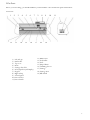
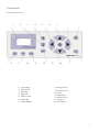
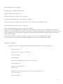
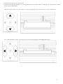
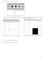
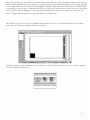
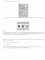
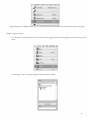
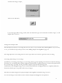
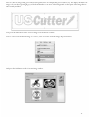
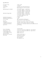
PCUT
Users
Manual
Contents
Welcome
........................................................................................................................................................................... 3
PCut Parts ......................................................................................................................................................................... 4
Front View
...................................................................................................................................................................... 4
Right Side View .................................................................................................................................................................. 4
Left Side View
Back View
Control Panel
................................................................................................................................................................ 5
........................................................................................................................................................................ 5
................................................................................................................................................................. 6
Control Panel Overview
............................................................................................................................................... 6
Jog Mode ............................................................................................................................................................................ 8
Pressure Setting Mode
…............................................................................................................................................... 9
Test Mode ......................................................................................................................................................................... 10
Repeat Mode ..................................................................................................................................................................... 11
Cutting Speed Mode ......................................................................................................................................................... 12
X/Y Axis Scale Compensation Modes
Setting up
..................................................................................................................... 13
....................................................................................................................................................................... 14
Selecting a Location for Your Cutter
......................................................................................................................... 14
Unpacking ........................................................................................................................................................................ 14
Installing the Pen
............................................................................................................................................................. 15
Installing a New Blade ...................................................................................................................................................... 17
Replacing a Worn Blade
............................................................................................................................................. 18
Connecting the PCut to a Computer
............................................................................................................................... 19
Install SignBlazer Software ............................................................................................................................................... 20
Preparing the PCut for Cutting
Step By Step Instructions
Starting SignBlazer
....................................................................................................................................... 20
....................................................................................................................................... 24
........................................................................................................................................................ 24
Making a Simple Cut in SignBlazer
Importing
............................................................................................................................... 26
...................................................................................................................................................................... 29
Cutting From an Imported File ........................................................................................................................................ 31
Converting a Raster Image to Vector Image .................................................................................................................... 31
-1-
Specifications
Troubleshooting
............................................................................................................................................................... 46
......................................................................................................................................................... 47
-2-
Welcome
Thank you for choosing the PCut cutter from USCutter.
The PCut is an exciting advancement in the world of vinyl cutting. It allows the user to perform advanced cutting
functions that were previously unavailable to entry level machines.
This manual is here to help provide a starting point in the learning process of the PCut cutter or to vinyl cutting in
general. Please read it thoroughly and follow the steps carefully to help insure a trouble free experience with your new
machine.
If you have any questions along the way, we have provided a few locations to go to get those questions answered. You
can post on the USCutter forums at forum.uscutter.com, submit a request for support on the support site at
support.uscutter.com or call customer service at 888-298-8143.
We hope you enjoy your experience with the Pcut and the USCutter family.
-3-
PCut Parts
Before you start cutting, you should familiarize yourself with the cutter and its basic parts and functions:
Front View
1
12
2
3
13
4
5
6
14
15
16
1) Left end cap
2) Pinch roller
3) Top cover
4) Beam
5) Carriage drive belt
6) LCD (Liquid Crystal Display)
7) Keypad
8) Right endcap
9) Control panel
10) Power Socket
11) Power Switch
7
2
17
8
18
9
10
11
19
12) Rubber foot
13) Feed Roller
14) Scale
15) Strip Cushion
16) Trimming Groove
17) Carriage
18) Carriage Arm
19) Kill Switch
-4-
Back View
1
1
1) Pinch Roller Release Levers
Pinch Rollers can be released (either to be moved from side to side or to allow vinyl to be easily fed below them bylowering
the release levers. Pinch rollers should be adjusted so that one is positioned on each side of the vinyl (or other media) to be cut
and should only be lowered onto an area of the feed roller below that has traction (the rough area).
-5-
Control Panel
Control Panel Overview
1
8
2
9
1)
2)
3)
4)
5)
6)
7)
3
10
LCD Display
Blade Down
Blade Up
Blade left
Media feed in
Blade right
Online/Offline
4
11
5
6
12
7
13
14
8) Setting Increase
9) Setting Decrease
10) Pause
11) Mode Select
12) Media feed out
13) Origin set
14) Reset button
-6-
First, to be able to use/adjust any of the functions from the cutter, it must be “Off Line”.
When you first turn on the cutter you will see
a short startup process followed by this display
To switch the machine to offline mode press the online button (7).
X=+0.00
Y=+0.00
This is Jog mode, the first in the 7 available Off Line modes.
From here, you can now press the Mode button (11) to cycle through the modes
-7-
Jog Mode
Jog Mode is used to position the vinyl and cutting blade. You can use the target button to reset
the origin of the next cut to be made. You can also make a test cut to witness the current speed
and pressure settings or check the blade depth while in the down cutting position. Make sure that
when setting the blade position it is clear of the red emergency “kill” switches on either side of
the cutter.
Pause button
Cuts a small rectangle with the current speed and pressure settings. Useful in
determining the proper pressure/speed settings to be used.
On Line Button
Returns the cutter to its origin location and returns to “On Line” status.
Mode Button
Cycles through the 7 Off Line modes.
Directional Buttons
Moves the vinyl and blade.
Target Button
Sets the current vinyl/cutting blade location as the new origin. The origin will be the
starting position of the vinyl/blade on the next cutting job that is sent to the cutter.
Up/Down Buttons
The Down Button will lower the cutting blade into the down cutting position. This
can help you determine if the pressure setting needs to be adjusted before cutting.
If the blade is left in the down cutting position then the progress
of the pressure setting can be seen while adjusting the pressure
setting in the Pressure Setting Mode.
The Up Button will return the cutting blade to its regular
position.
Plus/Minus Buttons
(has no function in this mode).
-8-
Pressure Setting Mode
The Pressure Setting Mode is used to adjust the pressure of the cutting blade. Thicker materials
can require more pressure. The pressure should be strong enough to fully cut the top vinyl but not
strong enough to cut through the backing attached to your vinyl. If you are unsure of the cutting
pressure that you should use, it is advised to make a test cut. This can be done by holding the Test
Button in this mode or by returning to Jog Mode and pressing the Test Button. You can see how
the pressure effects the down cutting position of the blade by returning to Jog Mode and using the
Up/Down Buttons.
On Line Button
(has no function in this mode).
Mode Button
Pause Button
Directional Buttons
Target Button
Up/Down Buttons
Cycles through the 7 Off Line modes.
Returns the cutter to Jog Mode.
(has no function in this mode).
(has no function in this mode).
(has no function in this mode).
Plus/Minus Buttons
Increases/decreases the pressure used during cutting (ranges from 0
to 200). Thicker materials may require more pressure. The amount
of pressure used can be seen by going to the Jog Mode and using the
Up/Down buttons to switch the blade from the original position to
the Down cutting position.
-9-
Test Mode
Test Mode is used to create a test pattern that shows various cuts in a number of directions. Most
simple tests (those to check the pressure and speed settings) can be done more efficiently by
pressing and holding the Test Button from any of the other modes. If you would like the test to be
performed multiple times, you can set the number shown on the display screen to the amount of
times you would like to test (from 1 to 255). For most situations, 1 test will be sufficient.
Online Button
Cuts a test pattern the number of times shown on the display
screen, using the current speed and pressure settings.
(has no function in this mode).
Mode Button
Cycles through the 7 Off Line modes.
Returns the cutter to Jog Mode.
(has no function in this mode).
(has no function in this mode).
(has no function in this mode).
Directional Buttons
Target Button
Up/Down Buttons
Plus/Minus Buttons
Decreases the number of test patterns to/Increases be cut
(ranges from 0 to 255).
This should not be set to 0 (zero), as this will cause the cutter to
cut test patterns until it is turned off.
- 10 -
Repeat Mode
Repeat Mode allows you to cut an exact duplicate of the last cut that was sent to your cutter. The
number of repeats made can be selected with the Plus/Minus Buttons. When you are ready for the
repeat cuts to be made, press the On Line Button. Although some software allows you to jog
(move) the cutter before cuts are made, since you are bypassing the software by making a cut
directly from the cutter, no software adjustments will be accounted for. If the blade or vinyl
needs to be moved, please use the Jog Mode.
Mode Button
Returns the cutter to Jog Mode (If held down, a test cut
will be made).
On Line Button
Starts the Repeat function.
Pause Button
Directional Buttons
Target Button
Up/Down Buttons
Returns the cutter to Jog Mode.
(has no function in this mode).
(has no function in this mode).
(has no function in this mode).
Plus/Minus Buttons
Plus/Minus Buttons Increases/Decreases the
number of repeat cuts to be made. These will be a
repeat of the last cut that was sent to the cutter.
Once the On Line button is pressed, all of the cuts will be
made in succession.
- 11 -
Cutting Speed Mode
Cutting Speed Mode is used to adjust the speed of the cutter. Most cuts can be made at high
speeds but if a problem is occurring where accuracy or detail is being lost in the cut, a slower
cutting speed may solve the problem.
On Line Button
Mode Button
Pause Button
Directional Buttons
Target Button
Up/Down Buttons
Plus/Minus Buttons
Returns the cutter to Jog Mode (If held down, the cutters
status will return to On Line).
Cycles through the 7 Off Line modes.
Returns the cutter to Jog Mode.
(has no function in this mode).
(has no function in this mode).
(has no function in this mode).
Increases/Decreases the speed of the cutter (from 10 to 80 in
increments of 10).
- 12 -
X/Y Axis Scale Compensation Modes
The X and Y Axis Scale Compensation Modes are used to correct problems when the cuts being made
are not the same scale as they are intended. The X axis effects the size of cuts across the width of the
vinyl while the Y axis effects the size of cuts along the length of the vinyl. If the cuts being made are not
the correct size, increase or decrease the number that coincides with the problem axis until the cuts are
correct.
On Line Button
(has no function in this mode).
Mode Button
Cycles through the 7 Off Line modes.
Pause Button
Returns the cutter to Jog Mode.
Directional
Buttons
Target Button
(has no function in this mode).
Up/Down
Buttons
(has no function in this mode).
Plus/Minus
Buttons
Increases/Decreases the amount of
X/Y scale compensation. The larger
the number is, the larger the cut made will be. This
compensation can be used to remedy problems
where the cut being made is smaller or larger than it
was intended.
(has no function in this mode).
- 13 -
Setting up
Selecting a Location for Your Cutter
The first step to setting up a PCut is finding a good location for the machine. Consider these factors when you are selecting a
suitable place:
The stand has a footprint of approximately 25” x 35”. If you intend on using the PCut without the stand, you will need a
desktop space of approximately 35” x 18” with the included media rollers attached, or 35” x 11” without.
You will need to have access to both the front and rear of the machine for operations as well as for loading and
unloading new vinyl rolls. Try to find a space with adequate access to both the front and back of the machine.
Since the PCut is a precision cutting device, you will want to find a location that will be stable to insure cutting
accuracy. Whether placing the unit on the floor or a table top, the accuracy of the machine will be directly related to the
stability of the platform it is placed on. Find a sturdy floor space or table top for the machine and consider a location that
will be out of the way of people and other machines with moving parts while the cutter will be operating. Excessive
moving of the machine can not only disrupt accuracy of cutting but may also cause electrical components inside the
machine to dislodge and require otherwise unnecessary repairs and maintenance.
Fans, located inside of the PCut cutter, can draw in outside dust from the area surrounding the cutter. Excessive
buildup of dust can cause either mechanical or electronic malfunctions. Keeping the PCut cutter as dust free as
possible will help ensure trouble free operation. Try to find an area for the PCut cutter that will be free of any
excessive dust.
All cutters will produce a small amount of noise while operating. Please take this into consideration when selecting a
location for your cutting purposes.
Do not remove the grounding pin from the power cord or attempt to use the cutter when it has not been properly
grounded.
- 14 -
Unpacking
Remove all contents from your shipping box. If you have not already done so, please refer to the Unpacking Guide to
take account of all of the included components.
Cut the restraining plastic straps from the cutter. Be careful to not cut anything but the restraints.
If you purchased your PCut cutter with a stand, please refer to the included PCut stand assembly guide at this time and
complete assembly of the stand.
If you will be using your PCut as a table top unit without a stand and would like to use the included table top rollers, please
refer to the table top roller instructions.
Installing the Pen Holder
Most new users will benefit from practice “cutting” with the supplied pen carriage until they are comfortable with normal
operations of the PCut and cutting software.
To install the pen holder:
- 15 -
Loosen the locking knob on the
carriage arm.
Drop the pen attachment
into place.
Tighten the locking knob on the
carriage arm.
It may be easier to install the pen (or blade) carriage after the lid on the PCut has been raised allowing more working
room.
- 16 -
Remove the top cap, the pen and the spring. Replace the pen and/or spring as necessary. Slide the spring onto the pen from
the top and insert it back into the pen carriage.
Replace the holder cap and screw into place.
Once you are ready to make cuts with the PCut you can attach the blade carriage.
Installing a New Blade
Unscrew the cap
from the Blade
holder.
Remove the
protective cover
from a new
blade.
Insert the blade
into the top of
the Blade holder.
Screw the cap back on and Adjust the
blade exposure until the blade
tip is protruding approximately
1/64th an inch.
- 17 -
Loosen the locking knob on the
carriage arm.
Place Blade carriage (blade side
down) into the carriage arm.
Tighten the locking knob on
the carriage arm.
Replacing a Worn Blade
First remove the blade carriage from the carriage arm
Unscrew the cap off of
the blade holder.
Press up on the release button
located on the bottom of the blade
holder to raise the
blade and remove it.
Follow the remaining steps from “Installing a New Blade” above.
- 18 -
Connecting the PCut to a Computer
Attach the power cord first to the PCut unit.
Plug in the unit and turn on the power.
If Using the Serial Cable to connect the PCut to a Computer:
Connect Serial Cable (first to the PCut, then to the computer).
Your PCut setup is now complete and you are ready to move to the software installation section.
If Using the USB Cable to connect the PCut to a Computer:
Connect the USB cable (first to the PCut, then to the computer)
If Windows automatically installs the needed drivers, your installation is complete proceed to “Finding your COM port”.
If Windows does not install the needed drivers, but the found new hardware wizard appears, follow the instructions on screen,
using the supplied drivers from the banana digital driver disk or download the FTDI driver from the support.uscutter.com
website under downloads.
If the found new hardware wizard does not appear, navigate to Control Panel>Add Hardware, to initiate
it. Then follow the on screen instructions using the supplied drivers from the banana digital driver disk.
-Finding Your COM Port
First navigate to the Device Manager by following the below instructions for your operating system:
Windows95/98/Me:
Click Start, then select Settings -> Control Panel.
Select Device Manager.
Windows2000/XP:
Click Start, Then Right-click “My Computer” then select Properties.
Select the Hardware tab.
Click the Device Manager button.
Windows Vista/7
Click Start, Then in the "Start Search" box, Type "Dev" (without pressing enter);
wait for a list to show up.
Click Device Manager.
- 19 -
Expand the section labeled “Ports (COM & LPT)”.
Make a note of which number COM Port is associated with “USB Serial Port”.
You will need this information to properly install your software.
Install SignBlazer Software
Insert the SignBlazer Elements CD into your computer.
Select “Run Setup” .
Follow the on screen instructions.
When asked what cutter you want to use, select the Creation PCut CTE 630
When asked what port your cutter uses select the COM Port that corresponds with your setup (Noted above from the
“Finding Your COM Port” section of the manual).
Do not change the Baud Rate, Data Bits, Stop Bits, or Parity options.
Make sure the Flow Control option is set to Hardware.
Preparing the PCut for Cutting
If you are going to be cutting from a roll of vinyl (or other material), and did not purchase a stand with your PCut cutter, then
you may want to use the included table top rollers to hold the roll. The table top rollers will work best if they are allowed to
hang slightly over the edge of a table so that the hooks on the cutter side are allowed to fully connect with the cutter, increasing
stability.
If you are going to cut from a single sheet instead of a roll, then skip the next step on placing a vinyl roll. All other steps will
be the same.
- 20 -
Place the roll on top of the rollers. If using the stand, you can move the roller caps up against either side of the vinyl roll to keep
the roll from shifting right or left during cutting.
Release the Pinch Rollers by lowering the Pinch Roller Release Levers.
Feed the vinyl underneath the pinch rollers (if working from a single sheet instead of a roll the vinyl can also be feed from the
front).
- 21 -
Adjust the pinch rollers from side to side so there is one roller on each side of the vinyl.
Leave a gap of between ½-1 inch from the edge of the roller and the edge of the vinyl on both sides.
Engage the Pinch Rollers by pulling up the Pinch Roller Release Levers.
- 22 -
If the PCut is not already on, turn it on now
Take the cutter Off Line and make sure it is in Jog Mode (If you are unsure of how to do this, please refer back to the Control
Panel section of this manual).
Adjust the vinyl to where you want to make your cut by using the Up and Down Arrow Keys on the Control Panel.
Now, adjust the Blade to where you want your cut to be made by using the Left and Right Arrow Keys.
- 23 -
Now press the target key to tell the cutter that this is the location where you would like the cut to begin.
If you would like to make other adjustments to the pressure, speed, or other settings you can do so now. If you are setting up for
your first cut with the machine then the default values should be a good starting point.
You can now return to Online Mode. Your cutter is now ready.
Step By Step Instructions
Starting SignBlazer
Making sure that the USCutter PCut is turned on and in On Line mode before starting the SignBlazer software will help
avoid communication problems between the cutter and software.
Open the SignBlazer Software (The Default location will be in the Programs Folders under “SignBlazer Elements for
USCutter”).
Navigate to this folder and select “SignBlazer Elements for USCutter”.
- 24 -
SignBlazer will attempt to download update files.
If it fails, cancel the update process (By Pressing the Cancel button on the error window and then the OK on the
confirmation window) and the program will start regularly.
- 25 -
We will be working in Trial Mode. Select “Trial Mode” from the following screen, then select “Yes” from the confirmation
window.
Now SignBlazer is open and you are looking at the main SignBlazer screen.
Making a Simple Cut in SignBlazer
You can create images from scratch using the various tools in SignBlazer. For this tutorial, we will be drawing a simple
square just to show the steps of making a cut from SignBlazer.
- 26 -
Select the Square tool at the top of the window.
Now draw a square by clicking first in the main window…
And then moving the mouse to determine the size of the square
desired, and clicking a second time.
Now to cut this simple shape from the cutter:
Select Cutter from the top selection menu.
- 27 -
Please make sure that your cutter is turned on and in On Line mode before proceeding. Also make sure that you have vinyl (or
another cuttable material) in the cutter and ready to go by following the steps in the “Preparing the Pcut for Cutting” (page 20)
section of this manual. It is always best to start the SignBlazer software with the cutter turned on and in On Line mode. If this
step is missed you may experience communication issues between the cutter and the software. If this occurs, please turn off the
cutter, go back to the main SignBlazer screen by pressing the Finish button from the top selection menu of any of the subscreens, and then turn the cutter back on and ensure that it is in On Line mode.
This will take you to the cutter screen of SignBlazer Elements where you can see a representation of how your cut will be
made when sent to the cutter and other various cutter options.
Since this is a simple cut, no adjustments need to be made here. We can tell the software we are ready to cut by pressing the
cut button in the top selection menu.
- 28 -
And then pressing “Cut Tile” in the Cut Tile window:
When you are finished, you can go back to the main SignBlazer screen by pressing the Finish button in the top selection menu.
Importing
Drawing images from scratch in SignBlazer may prove to be somewhat different than imaging software that you are more familiar
with. If you would rather create the images to be cut in another software or you already have designs finished that need to be cut,
then you can just import the finished artwork into SignBlazer and cut from there.
Most major raster and vector image files are supported in SignBlazer Elements including dxf, eps, ai, bmp, tif, gif, pcx, tga, jpg,
pcd, pct, psd, cmx, ps,and wmf.
You can import to SignBlazer one of two ways:
Using the Clipboard
You can import from the clipboard by first copying or cutting an image opened from another software program, and then
placing it into SignBlazer by selecting Clipboard Paste from the Edit drop down menu.
- 29 -
Images imported via Clipboard Paste may not retain the same dimensions that they held in another software program.
Using the Import Function
You can import an image that has been saved from another program by first selecting Import from the File drop down
menu:
Then navigate to the saved file by using the Folder and Drives menus:
- 30 -
Then Select the image to import,
And select the OK button.
If you are having trouble locating your file, make sure that the file type is selected from the “List Files of Type”, or “All
Graphic Files” is selected.
Cutting From an Imported File
If the file imported is already a vector image then it is now ready to cut or be further edited within SignBlazer. If you are ready
to cut, you can follow the steps in the previous section “Making a Simple Cut in SignBlazer”( page 26).
If the image imported is a raster image then a few more steps will need to be taken to get the file ready for cutting.
Converting a Raster Image to Vector Image
The difficulty of converting a raster image to a vector image will vary greatly depending on the amount of contrast in the image.
The image to be cut should be darker than the background and should have a significant amount of contrast and separation from
the rest of the image. If possible, the image should be completely separated from the background
and be black in color (though the image we chose for this demonstration has a background and is not completely darkened to
demonstrate that the process is possible with a variety of images).
First make sure that the image has been properly imported into SignBlazer and that the image is selected.
You can tell an image is selected when it shows a Border and Square Bounding Boxes in its parameter.
- 31 -
With the image selected, select “Monochrome – 1 bit” from the Mode section of the Image drop down menu.
Sometimes an imported image will already be in monochrome but will still need to be vectorized before being cut. If the image
imported is monochrome than you can skip ahead to the "vectorise" section.
The “Convert Image to monochrome” window will appear.
Where you place the slider will determine how much of .Now you can adjust the Threshold Level sliderthe image
will be included in the monochrome conversion (which is to become the image that will be cut). Anything darker than the
level set on the Threshold slider will be included in the cut and anything lighter will not.
- 32 -
Since we chose an image with good contrast and separation for our example this process will be easy. We simply check that our
image to be cut shows up in light grey or black and that there is no areas of the background or other parts of the image that are
unnecessarily included.
Now press the OK button on the “Convert Image to monochrome” window.
Now to convert a monochrome image to a vector, select “Vectorise” from the Image drop down menu.
And press the OK button on the Vectorise Image window.
- 33 -
You are now left with 1 monochrome image and 1 vectorized image. This may be difficult to see as they are probably layered
directly on top of one another. If you grab one image and drag it you will see the other image left behind. You can now delete
the monochrome image that has been left behind as it is no longer needed.
The cutting process for a vectorized image is the same as it is for cutting a simple image. You can now follow the steps from the
“Making a Simple cut in SignBlazer” (page 26) section of this manual to make your cut.
- 34 -
Specifications
PCut Release Date
Controller
Control Panel
Driver:
Maximum Paper Feed Width
Maximum Cutting Width
Maximum Cutting Speed
Maximum Cutting Thickness
Pressure Range
Precision
Plotting Pen
Communications Protocol
Communications Interface
Input Power
Power Consumption
Customer Service Line
Technical Support Line
Technical Support Website
Customer Forums
Manufactured For and Sold
Directly By
October, 2007
16 bit CPU
2x8 LCD 13 button thin-film keyboard
High stepping motor, micro-step driver
28.74 inches (730mm) - 24 inch model
39.37 inches (1000mm) - 36 inch model
51.18 inches (1300mm) - 48 inch model
25.20 inches (640mm) - 24 inch model
35.63 inches (905mm) - 36 inch model
47.64 inches (1210mm) - 48 inch model
15.75 inches (400mm) per second
.039 inches (1mm)
0 - 400g
.1mm
All 11.4mm diameter plotting pens
DM-PL HP/GL; automatic identification
USB (Universal Serial Bus) and RS-232 Serial (9 pin
110 VAC/ 220 VAC 50 Hz / 60 Hz (auto-switching)
Standard power cord included with unit is US-standard 110 VAC
grounded plug.
Less than 100VA
425-481-3555; option #3. Available 8am - 5pm, Mon-Fri
425-481-3555; option #2 Available 9am - 4pm, Mon-Fri
support.uscutter.com
forum.uscutter.com
19510 114th NE, Suite C-1
Woodinville, WA 98072
425-481-3555 phone
888-640-0720 fax
www.USCutter.com
- 35 -
Troubleshooting
Problem
The cutter is unresponsive to
communications from the
computer and software.
placed in the on position.
Solution
Communication issues can arise if the cutter was powered on while
the software is trying to send data to or from the cutter. Exiting
the cutter screen of SignBlazer and returning to the main
SignBlazer screen may resolve this issue. If not, save all work and
try exiting SignBlazer and restarting with the cutter powered on. It
is good practice to start SignBlazer with the cutter powered on to
avoid communication problems.
Make sure that your output device in SignBlazer (Found by selecting
File>Cutter from the menu on the main SignBlazer screen, and then
selecting Setup from the top menu buttons) is set to the correct COM
port. (Your COM port can be found by following the instructions in the
“Finding Your COM Port” section of this manual on page 19). You can
change your COM Port by right-clicking on the COM Port in the
device manager and going to the advanced section of the Port
Settings tab.
Adjust your Flow Control settings to Hardware by first locating
your COM Port in the device manager (By following the instructions
on page 19), then right-click the COM Port and select Properties.
On the Port Settings tab, change to Flow Control option to
Hardware.
Black boxes show up on theOne of the Emergency Kill Switches may be pressed or otherwise
Display Screen of the Controlengaged.
Panel when cutter is turned on. Make sure that nothing is pressing on either of the Kill Switches or
that they have not become stuck in the pressed position. If a
problem persists, with power off and the power cord
removed, check for crossed wires from one of the kill switches to
the motherboard.
The Display Screen on theThe cable transmitting data to the Display Screen may have become
Control Panel of the cutter isdisconnected. With power off and the power cord
not outputting a display.removed, remove the Right side panel from the PCut cutter
and verify that the cable is connected. If the cable appears to be
connected but there are still display problems, you can disconnect
the cable and reconnect it to make sure that a proper connection
has been established.
The Laser is not emitting light. If the laser is not lit while the power of the PCut is on, then
there may be a defect with the laser. Contact USCutter for laser
replacement options.
The PCut is not powering Try another outlet or surge protector or verify that the outlet
on when the Power Button isbeing used is sufficiently powered.
- 36 -
The PCut is not powering Power issues can be a result of a faulty or damaged power cord.
on when the Power Button isTry another cord on the PCut or test the power cord with
placed in the onanother device to verify that the power cord is working properly.
position.(continued)
If the problem is not a result of either the outlet or power cord,
there may be a connection problem inside of the machine. With
the power switch in the off position and the power cord
removed, remove the left side panel of the PCut cutter and
check all of the connections from the power cord and power
switch. Repair or replace as necessary.
While attempting to cut, theThe Locking Knob of the Carriage Arm may have become over
Blade of the PCut will not tightened and is protruding through the back of the Carriage Arm,
lower.blocking the arm from lowering. Loosen this until there is no
longer a blockage.
When starting the SignBlazerThis is a regular occurrence of the SignBlazer software and should
Software it fails to findnot be considered a problem. All features of the software will
updates.continue to work in trial mode without updates.
To deactivate the update process, redirect the shortcut (of either the
desktop icon or start menu selection that you use to open the SignBlazer
software) to SignBlazer. Right-click it and select Properties. From
the Properties menu, change last section of the Target option from
“sb.exe” to “sbnt.exe”. Press the Apply button, then the OK
button. This will bypass the update process.
Cuts are jagged or inconsistent. The Blade may be dulled or damaged. Replace with a new blade
and try again. Make sure that the blade can turn freely (by
attempting to turn it with your fingers while the release button of the Blade
Carriage is pressed).
Adjust the blade depth of the Blade Carriage(page 17) and Pressure
Setting on the cutter(Page 9) until you are getting solid, uniform
cuts. Start with a blade depth of around 1/64th of an inch and a
pressure setting of 120 and try an increased pressure setting before
attempting to increase the blade depth.
Other solutions may be found by visiting the Customer Forums or Technical Support Website, or by calling the
Technical Support Line (Web page addresses and Phone number on the specifications page, 46).
- 37 -
- 38 -