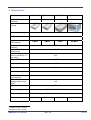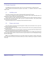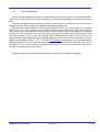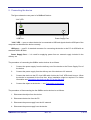
1
QMBox45 series devices:
QMBox45-8, QMBox45-16, QMBox45-24, QMBox45-64.
Technical Description and User Manual.
Revision 2.1.
1.
GENERAL INFORMATION .......................................................................................................................................2
2.
SPECIFICATIONS........................................................................................................................................................3
3.
ARCHITECTURE.........................................................................................................................................................4
4.
PRINCIPLE OF OPERATION....................................................................................................................................5
4.1.
4.2.
4.3.
5.
CONNECTING THE DEVICE ....................................................................................................................................7
5.1.
5.2.
6.
OSCILLATOR MODE ..................................................................................................................................................5
STREAM OUTPUT MODE ............................................................................................................................................5
SYNCHRONIZATION ..................................................................................................................................................6
CONNECTING THE DEVICE TO THE PC FOR THE FIRST TIME ......................................................................................8
CONNECTING TO THE OBJECT .................................................................................................................................10
SOFTWARE.................................................................................................................................................................11
6.1.
6.2.
QMLAB SOFTWARE SUITE ......................................................................................................................................11
SOFTWARE DEVELOPMENT KIT ...............................................................................................................................11
Contacts:
http://www.RTechElectronics.com
[email protected]
- Common questions
[email protected]
- Sales department
[email protected] - Technical support
1. General information
The QMBox45 series devices are multichannel DACs with USB 2.0 interface. Depending on
their model, the devices may feature 8 to 64 differential analog outputs.
QMBox45 series devices are versatile tools for generating test and control signals. The devices
are designed for analog control of measuring and testing equipment parameters. They can be used
as generators of sinusoidal signals, rectangular and sawtooth pulses, as well as any multiphase
arbitrary waveforms.
Features
•
Ultra-low glitch impulse;
•
Galvanic isolation of analog outputs from USB;
•
Continuous data streaming from PC memory or hard disc allows to generate non-periodic
signals of arbitrary form and duration;
•
Free PC software allows to:
- set the form and parameters of generated signals individually for each channel
- set the frequency and phase of output signals with quasi-zero step
- “play” files of arbitrary length through the DAC
QMBox45 User manual
Rev. 2.1.
2 of 11
2. Specifications
Model
Number of output
channels
QMBox45-8
QMBox45-16
QMBox45-24
QMBox45-64
8
16
24
32 to 64
3 MS/s
4-8 MS/s
Design
Output signal range
± 10 V
DAC resolution
16 bits
Aggregate throughput
(all channels)
Conversion rate (one
channel)
Max. differential
nonlinearity
Output voltage settling
time (to ±0.0015% of
full scale)
Typical THD+Noise
1 MS/s
2 MS/s
125 kS/s
± 1,5 LSB
2 µs1
83 dB2
Reference limiting error
0.05 %
Typical glitch impulse
1.5 nV*s
Max. output impedance
0.002 Ω
Max. output current
(per channel)
Galvanic isolation of
analog outputs from
USB
PC interface
30 mA
1 kV
USB 2.0
Power supply
External environment
Dimensions, mm
1
2
100–240 V AC or 24 V DC
from +5°С up to +55°С with relative moisture from 5% up to 90%
140x190x40
140x190x60
140x190x80
260x260x160
Output current ≤ 10 mA
Output current ≤ 10 mA
QMBox45 User manual
Rev. 2.1.
3 of 11
3. Architecture
The basic components of QMBox45 devices are 8-channel QMS45 DAC modules that are
installed into one case. Depending on the number of modules installed, a QMBox45 device can have
1-, 2-, 3- or 8-module configurations, thus, different models of the device differ in the number of output
channels.
Model
Number of the
QMS45 modules
installed
Number of
output channels
Dimensions
QMBox45-8
QMBox45-16
QMBox45-24
QMBox45-64
1
2
3
4 to 8
8
16
24
32 to 64
140x190x40 mm
140x190x60 mm
140x190x80 mm
260x260x160 mm
The two-module device QMBox45-16 is used to demonstrate QMBox45 internal construction:
A – the assembled device;
В – the same device with the cover removed;
1 – Bottom shell
2, 3 – QMS45 DAC modules – 2 pieces
4 – Interface board that controls operation of the modules and ensures connection of the device to the
computer via USB
5 – Interconnect board that ensures electric connection of the modules to the interface board.
Inside the case the QMS45 modules are plugged into the slots of the interconnect board. This
board joins the modules into a single device and ensures electric connection of the modules to the
interface USB board. The interface board controls operation of the modules and ensures connection
of the device to the PC via USB.
*
This scalable modular architecture allows to combine modules of different types (ADC, DAC, Discrete
I/O, etc.) in a single device. These modules can be combined in one device in any configuration. For
detailed information about Combined devices, see
http://www.rtechelectronics.com/products/qmbox/index.php
QMBox45 User manual
Rev. 2.1.
4 of 11
4. Principle of operation
The QMBox45 series devices operate under PC control (OS Windows) via USB connection.
Output channels of the devices can operate in two modes – in “oscillator” mode and in “stream
output” mode.
4.1.
Oscillator mode
This mode is intended for the output of simple periodic signals and DC signals.
In this mode the software fills the internal buffer of the device with the data (the buffer size is 32
kSamples per channel) before the operation beginning.
After the receipt of a "Start" command from the software, the device starts to send the contents of
its internal buffer cyclically through the DAC at a rate of 125 kS/s per channel. This cyclical process
can continue as long as necessary.
During the operation there is no updating of the internal buffer contents.
4.2.
Stream output mode
This mode allows to generate non-periodic signals of arbitrary form and duration and to “play” files
of arbitrary length through the DAC.
During the operation in this mode the data in the internal buffer of the device updates permanently
from the PC memory.
During the data output from the internal buffer of the device through the DAC the software fills the
free part of the internal buffer with the new data from the PC RAM.
Since the software fills the internal buffer at a rate higher than the rate of data output through the
DAC, the data transfer session can last for however long, and data from the PC RAM passes through
the DAC without gaps.
Note! In every QMBox45 series device only 8 DAC channels can operate in stream output mode.
Other channels of the device (if the device model has more than 8 channels) can operate in oscillator
mode only.
QMBox45 User manual
Rev. 2.1.
5 of 11
4.3.
Synchronization
All the modules installed in the device are clocked by the same generator on the interface board.
That is why in the course of work the modules of the device are precisely synchronised with each
other.
However, sometimes it is necessary not only to synchronize the modules with each other, but to
precisely time the entire device to be started by a certain external event.
By default the device starts the data output through the DAC since after issuing the command
“Start” from a PC. This command can be executed within a few milliseconds. The exact execution
time of this command under OS Windows (that is not a real-time OS) is impossible to be learnt in
advance. For the cases when it is necessary to bind the start of the data output to any external event
with high precision one can use the external start synchronization mode. In this mode for the
beginning of the data output after the issuing the command “Start” from a PC it is necessary to give a
negative digital pulse (logical “1” - “0” - “1”) to the "SYN" contact of the device. The data output begins
right after logical “1” to “0” front arrives. The duration of the SYN impulse (i.e. of the logic “0”) must be
at least 50 ns. The “SYN” line has an internal pull-up resistor, so one can just short the “SYN” line to
“ground” to generate the required pulse.
Switching between start synchronization modes of data output is software-selectable.
QMBox45 User manual
Rev. 2.1.
6 of 11
5. Connecting the device
The figure shows the rear panel of a QMBox45 device:
“Link” LED
USB Port
Power Supply Port
“Link” LED — turns on when the device is connected to USB and signals that the USB port of the
computer has identified the device correctly.
USB port — type B. A standard connector for connecting the device to the PC via USB with an
standard USB A-B cable.
Power Supply Port — it is used for supplying power from an external supply included in the
delivery set.
The procedure of connecting the QMBox series devices is as follows:
1.
Connect the power supply from the delivery set of the device to the Power Supply Port of
the device.
2.
Connect the power supply from the delivery set of the device to AC network.
3.
Connect the device to the PC via a USB cable. At this the “Link” LED should turn on. When
the device is connected for the first time, driver installation might be required. For further
information see Connecting the device to the PC for the first time.
4.
Connect the object to the device — see Connecting to the object.
The procedure of disconnecting the the QMBox series devices is as follows:
1. Disconnect the object from the device.
2. Disconnect the device from the PC.
3. Disconnect the power supply from the AC network.
4. Disconnect the power supply from the device.
QMBox45 User manual
Rev. 2.1.
7 of 11
5.1.
Connecting the device to the PC for the first time
When the QMBox series device is connected to a Windows PC for the first time, it is necessary to
specify the location of the device driver.
Before connecting the device to the PC for the first time you should first insert the included CD
into the CD-ROM drive of your PC and only then connect the device to the PC via a USB cable.
As a rule, having detected a new device, Windows starts the Found New Hardware Wizard. In this
case you should follow its instructions, choosing not to go to the Windows Update site and specifying
the “\DRV” folder on the included CD as the location of the driver.
Windows might not start the Found New Hardware Wizard automatically, returning a driver error
message in the notification area (in the right bottom corner of the screen):
In this case you should start the Device Manager. In different Windows OS versions the Device
Manager is started differently. For example, in Windows 7 it can be started by right-clicking the
Computer icon, then – Properties, and then – Device Manager.
In the Device Manager QMBox device will appear as Unknown device. You should right-click on it
and select “Update Driver Software”:
QMBox45 User manual
Rev. 2.1.
8 of 11
After this the Found New Hardware Wizard will start up:
You should select “Browse my computer for driver software” and specify the “\DRV” folder on the
included CD as the location of the driver.
Then you should follow the instructions of the Wizard. Once the driver is successfully installed, the
“RT USB30K QMSystem Crate Controller USB” device should appear in the Device Manager:
This means that the device’s Interface board has been identified correctly by the PC, the driver is
installed and the device is ready to work.
Afterwards, when the QMBox device is connected to another USB port of the PC, Windows might
once again detect the QMBox device as “unknown device”. In this case you will have to repeat the
driver installation procedure as described above.
QMBox45 User manual
Rev. 2.1.
9 of 11
5.2.
Connecting to the object
The figure shows the front panel of a QMBox45 device (QMBox45-16 model, consists of 2 QMS45
modules):
37
19
20
1
37
19
20
1
Ports
Every QMS45 module which is a part of the QMBox45 device has its own port for the connection
to the object.
The port of the QMS45 module is described in the table, where where +DACi and –DACi are the
outputs of i-channel of the DAC (in a standard variant of the module delivery -DACi is connected
inside the module to analog ground AGND).
Pin
num.
1
2
3
4
5
6
7
8
9
10
11
12
13
14
15
16
17
18
19
Description
+DAC1 output
AGND – Analog ground
+DAC2 output
AGND – Analog ground
+DAC3 output
AGND – Analog ground
+DAC4 output
AGND – Analog ground
+DAC5 output
AGND – Analog ground
+DAC6 output
AGND – Analog ground
+DAC7 output
AGND – Analog ground
+DAC8 output
AGND – Analog ground
AGND – Analog ground
+ 15 V (analog supply) output
SYN – synchronization input1
Pin
num.
20
21
22
23
24
25
26
27
28
29
30
31
32
33
34
35
36
37
Description
-DAC1 output
AGND – Analog ground
-DAC2 output
AGND – Analog ground
-DAC3 output
AGND – Analog ground
-DAC4 output
AGND – Analog ground
-DAC5 output
AGND – Analog ground
-DAC6 output
AGND – Analog ground
-DAC7 output
AGND – Analog ground
-DAC8 output
AGND – Analog ground
- 15 V (analog supply) output
DGND – Digital ground
1
See Synchronization. Allowable potential on the SYN input is 0… 3,5 V relative to the Digital ground (contact
37). Note! Digital ground is galvanically isolated from the analog circuits (DAC outputs, AGND) and connected
to USB ground inside the device
QMBox45 User manual
Rev. 2.1.
10 of 11
6. Software
Software of the QMBox45 devices consists of the following components:
- QMLab software suite
- Software development kit (SDK package)
6.1.
QMLab software suite
The QMLab software suite is a universal software tool for working with QMBox devices. It allows
performing most standard tasks within measurement automation.
QMLab allows using the QMS45 device as a multichannel generator of sinusoidal signals, DC
signals and signals of arbitrary shape and duration (those are obtained by “playing” the user’s binary
files of arbitrary length through the DAC).
A detailed description of the QMLab suite is given in the “QMLab User Manual” document that
can be found on the site www.RTechElectronics.com and on the CD supplied with the device.
6.2.
Software development kit
Apart from the complete QMLab software suite, the QMBox45 delivery set includes an SDK
package, which is software and documentation designed for users who would like to create their own
applications for working with the device. This software consists of function libraries (API) and
examples of software development.
The user has a possibility to create full-blown applications using just a limited number of library
functions. These library functions are written so that even an inexperienced programmer who is not
well-versed in multithreaded and object-oriented programming can work with the device. A more
detailed description of the software development kit is given in the “QMBox Programming Guide”
document that can be found on the site www.RTechElectronics.com and on the CD supplied with the
device.
QMBox45 User manual
Rev. 2.1.
11 of 11