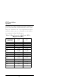
1
:34 Dewpoint PotentiaMeter for models WP4 and WP4-T 2SHUDWRU·V0DQXDO 9HUVLRQ 'HFDJRQ'HYLFHV,QF 'HFDJRQ'HYLFHV,QF 1(1HOVRQ&RXUW 3XOOPDQ:$ WHO ID[ ZZZGHFDJRQFRPZS ZS#GHFDJRQFRP 7UDGHPDUNV ´:3'HZSRLQW3RWHQWLD0HWHUµLVD UHJLVWHUHGWUDGHPDUNRI'HFDJRQ'HYLFHV,QF ©1998-2003 Decagon Devices, Inc., All rights reserved. :343RWHQWLD0HWHU Table of Contents &RQWHQWV ,QWURGXFWLRQ . . . . . . . . . . . . . . . . . . . . . . . . 1 About this Manual . . . . . . . . . . . . . . . . . . . . . . . . . . . . . . .1 Customer Service . . . . . . . . . . . . . . . . . . . . . . . . . . . . . . . .1 Warranty . . . . . . . . . . . . . . . . . . . . . . . . . . . . . . . . . . . . . . . . .2 Note to our WP4 Users . . . . . . . . . . . . . . . . . . . . . . . . . .3 Seller’s Liability . . . . . . . . . . . . . . . . . . . . . . . . . . . . . . . . . .3 $ERXWWKH:3 . . . . . . . . . . . . . . . . . . . . 5 WP4 Models and Options . . . . . . . . . . . . . . . . . . . . . .5 WP4 and Water Potential . . . . . . . . . . . . . . . . . . . . . . .5 How the WP4 works . . . . . . . . . . . . . . . . . . . . . . . . . . . .6 WP4 and Temperature . . . . . . . . . . . . . . . . . . . . . . . . . .7 *HWWLQJ6WDUWHG . . . . . . . . . . . . . . . . . . . 10 Components of your WP4 . . . . . . . . . . . . . . . . . . . . . . .10 Choosing a Location . . . . . . . . . . . . . . . . . . . . . . . . . . . . .10 Features . . . . . . . . . . . . . . . . . . . . . . . . . . . . . . . . . . . . . . . . . .11 Preparing the WP4 for Operation . . . . . . . . . . . . . .12 Portability . . . . . . . . . . . . . . . . . . . . . . . . . . . . . . . . . . . . . . . .13 7KH0HQXV . . . . . . . . . . . . . . . . . . . . . . . . . 15 The Main Menu . . . . . . . . . . . . . . . . . . . . . . . . . . . . . . . . . . .15 Changing Languages . . . . . . . . . . . . . . . . . . . . . . . . . . . . .16 Normal sampling mode . . . . . . . . . . . . . . . . . . . . . . . . . .16 Continuous mode . . . . . . . . . . . . . . . . . . . . . . . . . . . . . . . .17 System configuration . . . . . . . . . . . . . . . . . . . . . . . . . . . .18 Sample Equilibration Screen . . . . . . . . . . . . . . . . . . . . .23 &DOLEUDWLRQDQG9HULILFDWLRQ . . . . 25 Verification . . . . . . . . . . . . . . . . . . . . . . . . . . . . . . . . . . . . . .25 Verification Standards . . . . . . . . . . . . . . . . . . . . . . . . . .25 i :343RWHQWLD0HWHU Table of Contents When to Verify Calibration . . . . . . . . . . . . . . . . . . . . .26 How to Verify and Calibrate the WP4 . . . . . . . . .27 6DPSOH3UHSDUDWLRQ . . . . . . . . . . . . . . 31 Preparing the Sample . . . . . . . . . . . . . . . . . . . . . . . . . . . .31 Dry Samples . . . . . . . . . . . . . . . . . . . . . . . . . . . . . . . . . . . . . .32 Samples and Temperature . . . . . . . . . . . . . . . . . . . . . . .33 7DNLQJD5HDGLQJ . . . . . . . . . . . . . . . . 36 How WP4 takes Readings . . . . . . . . . . . . . . . . . . . . . . .37 Cautions . . . . . . . . . . . . . . . . . . . . . . . . . . . . . . . . . . . . . . . . . .37 Increasing your Accuracy . . . . . . . . . . . . . . . . . . . . . . .39 &RPSXWHU,QWHUIDFH . . . . . . . . . . . . . . . 41 Using Hyperterminal in Windows 98 and Windows 2000 . . . . . . . . . . . . . . . . . . . . . . . . . . . . .41 7KHRU\:DWHUSRWHQWLDO . . . . . . . . 44 Water potential . . . . . . . . . . . . . . . . . . . . . . . . . . . . . . . . . .44 Measuring Water Potential . . . . . . . . . . . . . . . . . . . . .45 Effect of Temperature on Water Potential . . . . . .46 &OHDQLQJDQG0DLQWHQDQFH . . . . . 48 Tools Needed . . . . . . . . . . . . . . . . . . . . . . . . . . . . . . . . . . . .48 Cleaning the Block and Sensors . . . . . . . . . . . . . . . . .49 Checking Calibration . . . . . . . . . . . . . . . . . . . . . . . . . . . .52 5HSDLU,QVWUXFWLRQV . . . . . . . . . . . . . . . 53 Shipping Directions . . . . . . . . . . . . . . . . . . . . . . . . . . . . . .53 Repair Costs . . . . . . . . . . . . . . . . . . . . . . . . . . . . . . . . . . . . . .55 Loaner Service . . . . . . . . . . . . . . . . . . . . . . . . . . . . . . . . . . .55 7URXEOHVKRRWLQJ . . . . . . . . . . . . . . . . . . 56 Problems and Solutions . . . . . . . . . . . . . . . . . . . . . . . . . .56 ii :343RWHQWLD0HWHU Table of Contents Component Performance Screen . . . . . . . . . . . . . . . .63 )XUWKHU5HDGLQJ . . . . . . . . . . . . . . . . . . 65 References: . . . . . . . . . . . . . . . . . . . . . . . . . . . . . . . . . . . . . . .65 Application Notes: . . . . . . . . . . . . . . . . . . . . . . . . . . . . . . .66 $SSHQGL[$ . . . . . . . . . . . . . . . . . . . . . . . . . . 67 Preparing Salt Solution . . . . . . . . . . . . . . . . . . . . . . . . . .67 iii :343RWHQWLD0HWHU Table of Contents iv :343RWHQWLD0HWHU Introduction 1. Introduction Welcome to Decagon’s WP4 Dewpoint PotentiaMeter, the research standard for measuring water potential. WP4 is the fastest, most accurate, and most reliable instrument available for measuring water potential using the chilled-mirror dewpoint technique. Whether you are a scientist or a student, WP4 will suit your needs. It is easy to use and provides fast, accurate results. We hope you find this manual informative and helpful in understanding how to maximize the capabilities of your WP4. About this Manual This manual is for use with the standard model WP4 and the temperature-controlled model WP4-T. Included in this manual are instructions for setting up your WP4, calibration, and maintaining and caring for your instrument. Please read these instructions before operating WP4 to ensure that the instrument performs to its full potential. Customer Service If you ever need assistance with your WP4, or if you just have questions, there are several ways to con- 1 :343RWHQWLD0HWHU Introduction tact us: Phone: Our toll-free customer service number is available to our customers in the US and Canada, Monday through Friday, between 8 a.m. and 5 p.m. Pacific time at 1-800-755-2751. For our customers outside of the US and Canada, our regular telephone number is (509) 332-2756 Fax: Our fax number is (509) 332-5158 When you fax us, please include your WP4’s serial number, your name, address, phone and fax number along with a description of your problem. E-mail: If you need technical support, you can send us messages via e-mail at [email protected] Again, please include as part of your message your WP4’s serial number, your name, address, phone, fax number, and return e-mail address. If you have a question about your application with WP4, please send your message with the above information to [email protected]. Warranty WP4 has a 30-day satisfaction guarantee and a one- 2 :343RWHQWLD0HWHU Introduction year warranty on parts and labor. To validate your warranty, simply contact us with the information on the warranty card included with this manual. You can return your warranty information by fax, e-mail, phone or by mailing the postage-paid card. Please include all the information requested on the card. It is necessary for Decagon to have your current mailing address and telephone number in case we need to send updated product information to you. Note to our WP4 Users This manual is written to aid the end user in understanding the basic concepts of water potential, enabling them to use our instrument with confidence. Every effort has been made to ensure that the content of this manual is correct and scientifically sound. Seller’s Liability Seller warrants new equipment of its own manufacture against defective workmanship and materials for a period of one year from date of receipt of equipment (the results of ordinary wear and tear, neglect, misuse, accident and excessive deterioration due to corrosion from any cause are not to be considered a defect); but Seller’s liability for defective parts shall in no event exceed the furnishing of replacement parts F.O.B. the factory where originally manufactured. Material and equipment cov3 :343RWHQWLD0HWHU Introduction ered hereby which is not manufactured by Seller shall be covered only by the warranty of its manufacturer. Seller shall not be liable to Buyer for loss, damage or injuries to persons (including death), or to property or things of whatsoever kind (including, but not without limitation, loss of anticipated profits), occasioned by or arising out of the installation, operation, use, misuse, nonuse, repair, or replacement of said material and equipment, or out of the use of any method or process for which the same may be employed. The use of this equipment constitutes Buyer’s acceptance of the terms set forth in this warranty. There are no understandings, representations, or warranties of any kind, express, implied, statutory or otherwise (including, but without limitation, the implied warranties of merchantability and fitness for a particular purpose), not expressly set forth herein. 4 :343RWHQWLD0HWHU About the WP4 2. About the WP4 WP4 is the fastest instrument for measuring water potential, giving readings directly in MegaPascals within five minutes. It measures water potential from 0 to -60 MPa with an accuracy of ±0.1 MPa from 0 to -10MPa and ±1% from -10 to -60 MPa. The instrument is easy to use and maintain, with simple checking of calibration. WP4 Models and Options The WP4 comes in two models to suit the needs of different users. Here is a brief description of each: WP4: Our standard model, adequate for most water potential needs. WP4-T: User-selectable internal temperature control model, uses thermoelectric (Peltier) components to maintain a constant internal temperature. WP4 and Water Potential Water potential is a measurement of the energy status of the water in a system. It indicates how tightly 5 :343RWHQWLD0HWHU About the WP4 water is bound, structurally or chemically, within a substance. Water potential is the vapor pressure of air in equilibrium with a sample in a sealed measurement chamber. For a more detailed description of water potential, please refer to Chapter 9, titled “Theory: Water Potential” of this manual. How the WP4 works WP4 uses the chilled-mirror dewpoint technique to measure the water potential of a sample. In this type of instrument, the sample is equilibrated with the headspace of a sealed chamber that contains a mirror and a means of detecting condensation on the mirror. At equilibrium, the water potential of the air in the chamber is the same as the water potential of the sample. In the WP4, the mirror temperature is precisely controlled by a thermoelectric (Peltier) cooler. Detection of the exact point at which condensation first appears on the mirror is observed with a photoelectric cell. A beam of light is directed onto the mirror and reflected into a photodetector cell. The photodetector senses the change in reflectance when condensation occurs on the mirror. A thermocouple attached to the mirror then records the temperature at which condensation occurs. WP4 then signals you by flashing a green LED and/or beeping. The final water potential and temperature of the sample is then displayed. 6 :343RWHQWLD0HWHU About the WP4 In addition to the technique described above, WP4 uses an internal fan that circulates the air within the sample chamber to reduce time to equilibrium. Since both dewpoint and sample surface temperatures are simultaneously measured, the need for complete thermal equilibrium is eliminated, which reduces measurement times to less than five minutes. The WP4-T gives you the option of controlling the sample temperature, by means of an internal thermo-electrically controlled module that monitors and stabilizes the sample block temperature according to how it is programmed. This can also help in making more rapid measurements. WP4 and Temperature Temperature gradients can often be of concern for making stable water potential measurements. Since water potential is influenced by temperature, best results are obtained by controlling the temperature. Samples that are not at room temperature during the read cycle will need to equilibrate to the temperature of the WP4 before accurate measurements of water potential can be made. Large temperature differences will cause longer reading times, since a complete and accurate reading will not be made until the sample and the instrument are within 0.1 degree of each other. To help you monitor the tem7 :343RWHQWLD0HWHU About the WP4 perature difference between your sample and the instrument, you can access a sample equilibration screen at the main menu. Though temperature control is usually unnecessary for most applications, there are some instances where it is desired. For this reason, Decagon offers a temperature-controlled WP4 model: the WP4-T. There are several advantages in having a temperature-controlled model. Here are a few major reasons: 1. Research purposes. To study the effects of temperature on the water potential of a sample, comparison of the water potential of different samples independent of temperature, or other water potential studies where temperature control is critical. 2. To minimize extreme ambient temperature fluctuations. If the laboratory and WP4 temperatures fluctuate by as much as ± 5°C daily, water potential readings can vary as much as ± 0.5 MPa on a dry soil sample. WP4-T The WP4-T has thermoelectric components installed that allow the instrument to maintain a set chamber temperature without the need of an external water bath. The WP4-T has an extra option in the System 8 :343RWHQWLD0HWHU About the WP4 configuration menu (see page 21) that allows the user to set the temperature. 9 :343RWHQWLD0HWHU Getting Started 3. Getting Started Components of your WP4 Your WP4 should have been shipped with the following items: • WP4 main unit • Quickstart guide • Certificate of Calibration • Power cord • RS-232 interface cable • 100 disposable sample cups • Operator’s Manual • 12 vials of 0.5 Molal KCl • Cleaning Kit Choosing a Location To ensure that your WP4 operates correctly and 10 :343RWHQWLD0HWHU Getting Started consistently, place it on a level surface. This reduces the chance that sample material will spill and contaminate the inside of the instrument. To protect the internal electrical components, and to avoid inaccurate readings, place your WP4 in a location where the temperature remains fairly stable. This location should be well away from air conditioner and heater vents, open windows, outside doors, refrigerator exhausts, or other items that may cause rapid temperature fluctuation. Features Function Keys LED indicator light LCD Sample drawer Front view of WP4 11 :343RWHQWLD0HWHU Getting Started Lid thumb-screw RS-232 interface Fan Power cord Plug ON/OFF Switch fuse well Back view of WP4 Preparing the WP4 for Operation After finding a good location for your WP4, plug the power cord to the back of the unit. Before turning it on, pull open the sample drawer (turn the knob to the “OPEN/LOAD” position). An empty disposable sample cup is usually placed upside-down in the drawer to protect it during shipment. Remove this sample cup and turn the instrument on. The ON/ OFF switch is located on the lower right corner of the WP4’s back panel. The following screens will appear on the LCD: PotentiaMeter Model WP4 v3.0 12 :343RWHQWLD0HWHU Getting Started Then: 0.00 MPa pF 0.00 0.0°C This is the main menu, displaying the water potential in both MegaPascals (MPa) and pF, and the sample temperature in °C. In order to provide the most accurate readings, WP4 should ideally be allowed a warm-up period of 30 minutes after turning it on. When you insert a sample into the chamber drawer and turn the drawer knob to the “READ” position, the instrument will begin the read cycle to measure the water potential of your sample. Portability On occasion you may want to take water potential measurements in the field where it is not feasible to take samples and return to the lab. The following is a procedure for powering your WP4 using your vehicle as a power source at sites where AC power is not readily available. 1. Purchase a portable power inverter that plugs into the 12V output (cigarette lighter) of your vehicle. We strongly recommend that this 13 :343RWHQWLD0HWHU Getting Started inverter have a continuous output of at least 140 Watts. 2. Place the WP4 on a level surface. Care should be taken to minimize temperature gradients that may affect the instrument while in the field. A Styrofoam box, for example, will help minimize temperature effects. 3. Plug the 12-volt inverter to the 12-volt output of the vehicle, or directly to the battery itself. 4. Plug the WP4 to the inverter, and turn it on. When the instrument is on, it draws 1 amp. Check the rating of your battery if you want to know how long it will power the instrument (for example, if your battery is rated for 60 amp hours, it will work for 60 hours when the vehicle isn’t running. 5. Allow the instrument to warm up for 30 minutes as you would in the lab. Check the calibration of the instrument before proceeding with sampling. 14 :343RWHQWLD0HWHU Menus 4. The Menus The Main Menu 0.00 MPa pF 0.00 0.0°C Every time you turn on your WP4, it will come to this screen. If this screen doesn’t appear, refer to Chapter 12 for troubleshooting instructions. As mentioned earlier, the water potential and sample temperature are displayed on the screen. On each side of the LCD there are buttons. Each button performs a different function depending on which mode you want. Following is a description of the modes and options you may use, and the buttons used to set them. continuous/normal mode language selection 0.00 MPa pF 0.00 system setup 0.0°C sample equilibration screen 15 :343RWHQWLD0HWHU Menus Changing Languages The WP-4 comes to you with English as the default on-screen user language. If you prefer not to use English, you can change it to one of a variety of other languages: German, French, Spanish, Italian, Swedish, Danish, Norwegian, Czech, Portuguese, or Japanese. This is done simply by pressing the upper right button of the instrument while it is not reading a sample. You will see the following screen: English -exitPress the upper right key again, and the next language option (German) will appear: Deutsch -zurückEach time you press the right button, the display will scroll to the next language option. Select the desired language, then press the lower left button to exit. Normal sampling mode The first time you turn on the WP4, it will be in normal sampling mode. In this mode, a single measurement is made each time you read a sample. Here is 16 :343RWHQWLD0HWHU Menus a brief summary of the normal sampling mode features: • single sampling (not continuous). • instrument may or may not beep after measurement is made, depending on the system setting. • green LED blinks until you turn the drawer knob to the OPEN/LOAD position. FRQWLQXRXVQRUPDOPRGH 0.00 MPa pF 0.00 0.0°C V\VWHPVHWXS VDPSOHWHPSHUDWXUHPHQX diagram of button options from main menu Continuous mode Continuous mode measures the water potential of your sample continuously until you turn the drawer knob to the OPEN/LOAD position. This can be useful in doing long term monitoring of samples that take an especially long time to come to vapor equilibrium, such as plants and leaves. In this mode, it 17 :343RWHQWLD0HWHU Menus will measure the sample, stop to display the water potential and sample temperature, then begin another read cycle. Between samples, it will signal you with the green LED flash, accompanied by the beeper, if it is enabled. Some find it helpful to connect their WP4 to a computer while in continuous mode in order to log and store data over time. For instructions on how to do this, see Chapter 8. To toggle between the normal and continuous modes, press the top left button. The display will show a small “c” to the left of the water potential readings: ´FµIRUFRQWLQXRXVPRGH c 0.00 MPa pF 0.00 0.0°C main menu with continuous mode enabled If you press the upper left button again, the “c” will disappear and you will be back in normal sampling mode. System configuration If you press the bottom left button while in the main menu, it will bring you to the system configu- 18 :343RWHQWLD0HWHU Menus ration menu. This menu allows you to make minor 0.00 MPa pF 0.00 0.0°C V\VWHPFRQILJXUDWLRQPHQXEXWWRQ system changes. You can change how the beeper signals after each sample and enter the calibration menu as well. %HHSHU ,FRQ %HHSHU &DOLEUDWLRQ PHQX 0RGHLQGLFDWRU FRQWLQXRXVVKRZQ + set T -Exit- WHPSVHW:37PRGHORQO\ System configuration menu Changing the beeper When you are sampling, the WP4 has two ways of notifying you that the water potential reading is completed for your sample: the beeper and a flashing green LED, located on the left front corner of the WP4’s case. In normal sampling mode, the LED will flash once when a sample is started. When it is 19 :343RWHQWLD0HWHU Menus finished the LED will flash continuously until the knob is moved to the OPEN/LOAD position (if not operating in continuous mode). You cannot turn off or change the LED flashing functions. There are three beeper options, represented by three icons: 0x No beeping. 4x Beeps four times, then stops. Beeps continuously until drawer is opened. definition of beeper icons The beeper can be turned off completely, it can beep momentarily (4 times) when the sample is finished and then stop, or it can beep continuously until the knob is turned to the OPEN/LOAD position. After you have adjusted the beeper setting, it will remain as you have set it until you change it again, and will not be affected by turning the instrument on or off. EXIT You may press the EXIT button (the lower left button) to exit back to the main menu at any time. Adjusting Calibration When you need to adjust calibration, press the upper right button in the system configuration menu, and you will be brought to the calibration 20 :343RWHQWLD0HWHU Menus menu. For more details on calibration and how to verify it, please refer to the next chapter. Setting the Temperature (WP4-T only) If you have a WP4-T, you have the ability to manually set your instrument’s sample chamber temperature. This is done by pressing the lower right button next to the “TE set” in the system configuration menu. The following screen will appear: 0 Adjust setpoint + -Exit- - 25.0 Adjusting the Setpoint Temperature Use the buttons next to the + and - buttons to adjust the target setpoint temperature (displayed in the lower right corner). If you press either button it adjusts in increments of .5°C. Note: Holding down the button will not increment the value, so you must press the button each time you wish to change this value. The target setpoint temperature roughly corresponds to the temperature at which you wish the chamber to read. Therefore, adjust the setpoint to the temperature that you want, then begin measurements to see how close your WP4-T comes to your desired temperature (this works best by putting the WP4 in continuous mode). After several samples, it 21 :343RWHQWLD0HWHU Menus should show consistent temperature readings. At this point, make any needed adjustment to the setpoint index number to reach your desired temperature. You will be able to adjust the index number between 40.5° and 15°C. If you press the - button after you reach 15°, it will disable the temperature control function until you raise the index number again. Setting Temperature Equilibration Time In the upper left corner, before the words “Adjust Setpoint” there is a number (default is 0). This value can be one of three integers: 0, 1, or 2, and is adjusted by pressing the upper left button. This number sets the level of temperature equilibration desired after the knob is turned to the READ position and before the WP4 begins to make measurements. A setting of 0 begins measurement immediately (as long as sample is not above 4°C of block temperature), 1 requires it to be within 1 degree, and 2 requires it to be within 1/2 of a degree. Note that if it is set to 0, the WP4 will begin taking readings when the temperature is within 4 degrees, but you will not get a final reading until the temperature has stabilized enough for the instrument to make an accurate final value. Important tips with the WP4-T 22 :343RWHQWLD0HWHU Menus • Before sampling, wait for approximately 30 minutes to let the chamber’s temperature to stabilize after turning it on. • The instrument may have a difficult time measuring the temperature of a sample that is being cooled if the ambient temperature is high. • When changing samples, the opening and closing of the drawer may cause the temperature in the chamber to fluctuate. Therefore, make sure to take more than one reading per sample to ensure that the temperature and water potential are stable between readings. • Never place a hot or warm sample in a cooled chamber, because condensation will form inside the chamber, causing errors in reading. Sample Equilibration Screen To see the temperature difference between your sample and the WP4, press the lower right button at the main menu. This screen can only be accessed when the drawer knob is in the OPEN/LOAD posi- 23 :343RWHQWLD0HWHU Menus tion. The following screen will appear: Ts = Ts - Tb = 24.9 -0.07 This screen shows the temperature difference between the sample (Ts) and the chamber block (Tb), allowing you to quickly check if the sample is too hot, which may cause condensation inside the chamber. Press the lower right button to exit. 24 :343RWHQWLD0HWHU Calibration and Verification Standards 5. Calibration and Verification Verification WP4 uses the chilled mirror dewpoint technique for measuring water potential. Due to the nature of this technique, periodic calibration is essential for the instrument to perform properly. The calibration slope is fixed during factory calibration. The user just resets the zero offset. Usually any changes in performance requiring recalibration are the result of chamber contamination. When this occurs, it changes the accuracy of your readings. In final testing at Decagon, the slope of the instrument is fixed. However, due to the reasons noted above, some drift is expected over time. This is compensated for by verification of the WP4’s calibration before use. Calibration can be done with any solution of known water potential. We recommend checking the calibration by measuring a fresh sample of 0.5 molal KCl and adjusting for any drift. Verification Standards Verification standards are specially prepared salt solutions that have a specific molality and water 25 :343RWHQWLD0HWHU Calibration and Verification Standards potential. The potassium chloride (KCl) verification standards are accurate, easy to use, and readily available from Decagon Devices. Most importantly, they greatly reduce preparation errors. Because of these reasons, we recommend using Decagon’s KCl Performance Verification Standard for the most accurate verification of your WP4’s performance. The standards are produced under a strict quality assurance regime. The accuracy of the standards is verified by an independent third party and are shelf stable for one year. If for some reason you cannot obtain Decagon’s verification standards and need to make a saturated salt solution for verification, refer to Appendix A. When to Verify Calibration The calibration of your WP4 should be checked with the KCl standard before each use. It should never be checked by measuring distilled water. The WP4 will read distilled water, but it is not a good choice for checking calibration, since as the humidity of the chamber approaches 100%, the sensor may be adversely affected. For batch processing, the instrument should be checked regularly against the KCl standard. This will alert you to the possibility of contamination of the unit or shifts in the calibration from other causes. 26 :343RWHQWLD0HWHU Calibration and Verification Standards How to Verify and Calibrate the WP4 Since errors in the calibration value result in errors in all values subsequently measured, care should be taken to do it right. Checking Calibration To check the calibration of your WP4, do the following: 1. Empty the whole vial of KCl solution into a sample cup and place it in the WP4’s sample drawer. For best results, make sure you wait for the KCl to come to temperature equilibrium at the sample temperature menu (Ts - Tb) before measuring it. 2. Carefully slide the drawer closed, being especially careful so the solution does not splash or spill and contaminate the chamber. 3. Turn the drawer knob to the READ position to make a reading. Make two readings. The second reading should be within ± 0.1 of the correct reading of the KCl standard at that temperature. At 20 °C this should be -2.19 MPa. At 25 °C this should be -2.22 MPa. If you’re operating in pF mode, it should read 4.35 pF at both 20 and 25 °C 27 :343RWHQWLD0HWHU Calibration and Verification Standards 4. If your WP4 is reading within 0.1 MPa of the KCl solution, proceed with sampling. If it is not, a change in calibration may have occurred, or the sensor chamber may be contaminated. For cleaning instructions, see Chapter 10. After cleaning, repeat these instructions. 5. If, after cleaning, you consistently get readings that are outside of the proper water potential of the KCl by more than ±0.1, a change in calibration has probably occurred. In this case, adjust the reading on the KCl measurement to its correct value. This is done by the following: Adjusting Calibration 1. Once you have determined that your calibration needs adjustment, enter the system configuration menu by pressing the lower left button in the main menu. Press the upper right button in the system configuration menu to enter the calibration menu. You will be guided through the calibration routine. The following screen will appear: Change the offset? yes no 28 :343RWHQWLD0HWHU Calibration and Verification Standards 2. If you wish to continue, press the button next to “yes.” To return to the main menu, press the button next to “no.” After selecting “yes,” the following screen will appear: Place standard in drawer and read 3. Empty the whole vial of KCl solution into a sample cup and place it in the WP4’s sample drawer. 4. Carefully slide the drawer closed, being especially careful so the solution does not splash or spill and contaminate the chamber. 5. Turn the drawer knob to the READ position to make a reading. Note: If you decide at this point that you do not want to continue with the calibration program, just return the knob to the OPEN/LOAD position and you will be returned to the main screen. After it has finished sampling the verification standard, it will bring you to the following screen: -2.19 MPa adjust + exit use these buttons to adjust the value 29 :343RWHQWLD0HWHU Calibration and Verification Standards 6. At this screen, adjust the water potential value to its proper value for the KCl solution at that temperature (-2.19 MPa at 20 °C; -2.22 MPa at 25 °C). Press the upper right button to move the value up, the lower right button to move it down. When it is at the value you want, press the Exit button. The value will be stored. Note: This is the only menu where these buttons can change the calibration, so you won’t hurt anything by pressing these buttons in other menus. 7. Read the KCl standard again in the normal sampling mode. It should read the proper value. 8. If after adjusting the calibration and cleaning the chamber you still are getting incorrect readings when reading the KCl, contact Decagon at 509 332-2756 (1-800-755-2751 in US and Canada) for further instructions. 30 :343RWHQWLD0HWHU Sample Preparation 6. Sample Preparation Your WP4 will continually provide accurate water potential measurements as long as its internal sensors are not contaminated. Careful preparation and loading of samples will lengthen time between cleanings and will help you avoid downtime and repairs. Preparing the Sample To prepare a sample, follow these steps: 1. 3ODFH WKH VDPSOH LQ D GLVSRVDEOH VDPSOH FXSFRPSOHWHO\FRYHULQJWKHERWWRPRIWKH FXSLISRVVLEOHWP4 is able to accurately measure a sample that does not (or cannot) cover the bottom of the cup. A larger sample surface area speeds up the reading by shortening the time needed to reach vapor equilibrium. It also increases instrument efficiency by providing more stable infrared sample temperatures. 2. 'R QRW ILOO WKH VDPSOH FXS PRUH WKDQ KDOI IXOO 2YHUILOOHG FXSV PD\ FRQWDPLQDWH WKH VHQVRUVLQWKHFKDPEHUPRUHLVQRWQHFHV VDULO\EHWWHU 31 :343RWHQWLD0HWHU Sample Preparation 3. 0DNH VXUH WKDW WKH ULP DQG RXWVLGH RI WKH VDPSOH FXS DUH FOHDQ Wipe any excess sample material from the rim of the cup with a clean tissue. Material left on the rim or the outside of the cup will contaminate the sensor chamber and will be transferred to subsequent samples. The rim of the cup forms a vapor seal with the sensor block when the drawer knob is turned to the READ position. Therefore, any sample material left on the cup rim will be transferred to the block, preventing this seal and contaminating future samples. 4. ,I D VDPSOH ZLOO EH UHDG DW VRPH IXWXUH WLPHSXWWKHVDPSOHFXS·VGLVSRVDEOHOLGRQ WKHFXSWRUHVWULFWZDWHUWUDQVIHU For shortterm storage (< 3 hours) the cup lid is acceptable. If it will be a long time before the measurement is made, seal the lid with tape or Parafilm completely around the cup/lid junction. Dry Samples Samples that have a water potential drier than about -300 MPa cannot be accurately measured with the WP4. However, samples with such dry water potential values are rare. When a sample’s water potential value is higher than about -300 MPa, WP4 will display an error message indicating the last reading it could make on that particular sample. For 32 :343RWHQWLD0HWHU Sample Preparation example, if you were measuring a dry sample and the following screen appeared: Sample too dry < -301.8 MPa this screen indicates that the last water potential reading the WP4 measured on this sample was -301.8 Megapascals. Therefore, the actual water potential of the sample is higher than the instrument’s components can measure. Samples and Temperature Samples that are 4 degrees colder or warmer than the instrument (chamber) temperature will need to be close to the WP4’s temperature before a fast, accurate reading can be made. Rapid changes in temperature over short periods of time will cause the water potential readings to rise or fall until the temperature stabilizes. If you have a WP4-T, you can set the chamber temperature to eliminate this problem. If you have a standard WP4, when the temperature stabilizes within one or two degrees of the chamber temperature, you can proceed with normal measurements. This is why the sample temperature screen is available for you to access (see chapter 4) before you read a sample: 33 :343RWHQWLD0HWHU Sample Preparation Ts-Tb = -0.49 As mentioned earlier, this screen shows you the difference in temperature between the sample temperature (Ts) and the block temperature (Tb). When Ts-Tb is in the 0 to -0.5 range, the temperatures are close enough that your read time should not be very long. If the temperature difference is outside this range (like -0.5 to -1.0), you may still begin sampling by turning the knob to the READ position, however your readings may take longer until the temperatures equilibrate. If samples are significantly warmer than the chamber when they are placed in it (Ts-Tb is a high positive number), condensation may occur and moisture will condense inside the block. In order to prevent this, do the following: 1. Place your sample in the chamber, slide the drawer closed and press the lower right button to access the sample temperature screen and look at the temperature difference. If the sample temperature is shown to be very high (a high positive number), take the sample out immediately and let it cool on a cold surface with the 34 :343RWHQWLD0HWHU Sample Preparation cup lid on it to preserve the moisture. Try not to cool the sample too much, since this will lengthen the equilibrium time. 2. After cooling it for a minute or so, place the sample back in and note the temperature difference. If it is close enough to the block temperature, turn the knob to the READ position to begin reading. There is a linear relationship between the sample’s dewpoint temperature and its water potential. The dewpoint decreases -0.12 °C per MPa. For example, a very dry sample at -40MPa can be 4.8 °C (-.12 x 40) above the chamber temperature without condensing. A sample at -1 MPa (fairly dry for most soils) can be 0.12°C above the chamber temperature without condensing. Therefore, if you know the general range of your sample’s water potential, you can gage at which temperature it will condense moisture. 35 :343RWHQWLD0HWHU Taking a Reading 7. Taking a Reading Once you have prepared your sample, you are ready to take readings. The process is simple: 1. Turn the sample drawer knob to the OPEN/ LOAD position and pull the drawer open. 2. Place your prepared sample in the drawer. Check the top lip of the cup to make sure it is free from sample residue (remember, an overfilled sample cup may contaminate the chamber’s sensors). 3. Carefully slide the drawer closed, being especially careful if you have a liquid sample that may splash or spill and contaminate the chamber. 4. Access the sample temperature menu (press lower right button) to watch the temperature difference between the sample and the instrument. 5. Turn the sample drawer knob to the READ position to seal the sample cup with the chamber. The instrument will beep once, and the green 36 :343RWHQWLD0HWHU Taking a Reading light will flash once to indicate that the reading cycle has started. In about 40 seconds, the first measurement will be displayed. How WP4 takes Readings WP4’s cooled mirror crosses the dew threshold numerous times to ensure the accuracy of readings. When the instrument has finished its read cycle, the water potential is displayed, accompanied by the LED flash and beeper (if you have the beeper enabled). Cautions • Never leave a sample in your WP4 after a reading has been taken. The sample may spill and contaminate the instrument’s chamber if the instrument is accidentally moved or jolted. • Never try to move your instrument after a sample has been loaded. Movement may cause the sample material to spill and contaminate the sample chamber. • Take special care not to move the sample drawer too quickly when loading or unloading liquid samples, in order to avoid spilling. • If a sample has a temperature that is much 37 :343RWHQWLD0HWHU Taking a Reading higher (Ts-Tb is a positive number) than the WP4’s chamber, take it out immediately, put the cap on it, and let it cool for a few minutes before sampling. Warm samples can cause condensation in the chamber and adversely affect subsequent readings. • The physical temperature of the instrument should be between 5°C—43°C. Between these temperatures, WP4 will measure samples of similar temperature quickly and accurately. • If you are sampling and a triangular warning symbol appears in the top right corner, this indi- -1.84 MPa pF 7.38 24.7 C cates that the mirror has become too dirty to give accurate measurements, and you need to clean the mirror and chamber before continuing to sample. For more details about this symbol, please refer to Chapter 12. For cleaning instructions, refer to Chapter 10. • If a sample has a water potential drier than about -60 MPa, WP4 will display a message, accompanied by the flashing light and beeper, notifying you that your sample is too dry to be 38 :343RWHQWLD0HWHU Taking a Reading accurately measured by the WP4. Following is an example: Sample too dry < -64.8 MPa This message will stay on the screen until you open the sample drawer. If you know that your sample’s water potential is below what the screen is telling you, your instrument’s sensors may have been contaminated and will need to be cleaned (see Chapter 10) or serviced (see Chapter 11). Increasing your Accuracy Under normal operating conditions, your WP4 should be reading with an accuracy of ±0.1 MPa from 0 to -10MPa and ±1% from -10 to -60 MPa. You can increase the accuracy of your WP4, provided you take certain precautions. Here are some steps you can take to improve your instrument’s accuracy up to ±.05 MPa: • For successful operation, the WP4 requires very precise temperature measurement and control. Therefore, the WP4-T model will work best for eliminating these variables. For a standard WP4 (not temperature-controlled), it is best to make measurements in a room with fairly constant, or 39 :343RWHQWLD0HWHU Taking a Reading slowly varying temperature. Large temperature variations from cycling air conditioning or forced air heating will degrade performance. • Intermittently run the 0.5 KCl in continuous mode between samples. Adjust your sample readings up or down according to the amount of variation from the 0.5 molal KCl. • If using a WP4-T, set the block temperature to best match the temperature of your samples. This will help reduce error resulting from changes in ambient temperature. 40 :343RWHQWLD0HWHU Computer Interface 8. Computer Interface Your WP4 was shipped to you with a standard RS232A interface cable. Using this, you can use your computer’s terminal program to send water potential data to your computer for further analysis and storage. Using Hyperterminal in Windows 98 and Windows 2000 To use Hyperterminal with your WP4, follow these steps: 1. Press the Start button and select Programs > Accessories > Hyperterminal and click on the Hyperterminal icon. 2. At the prompt, choose a name for this program (WP4 is a good one) and choose an arbitrary icon above to represent it. In future downloads, you will be able to click on this icon in have it already set up for you to download. Click the OK button. 3. A pop-up menu labeled “Connect To” will appear. Click on the scroll bar on the bottom of 41 :343RWHQWLD0HWHU Computer Interface the screen labeled “Connect Using” and select the COM Port your RS-232 cable is connected to. 4. A pop-up menu labeled “COM Properties” will appear, showing the port settings for the COM port you selected. Make sure the settings are the following: Bits per second, 9600; 8 databits, no parity, 1 stop bit, and flow control set to hardware. Click OK. 5. Plug your RS-232 cable to the COM port you selected and connect it to your WP4. Begin sampling. Your WP4’s data will be displayed on screen as it samples. It will be output in the following format: time (since chamber was closed), sample temperature, sample water potential, and sample water activity. Here is an example: Water Water time since temp potential activity sample was (°C) started 3, 24.3, -2.19, 0.9839 6. When you are finished sampling, you can print the data in the terminal session, or cut and paste it to a spreadsheet or text editor. If you want to 42 :343RWHQWLD0HWHU Computer Interface save the data, go into the Transfers menu and select “Capture text,” and designate where you would like it saved. 43 :343RWHQWLD0HWHU Theory 9. Theory: Water potential Water potential Water Potential is defined as the potential energy of water per unit mass of water in the system. The total water potential of a sample is the sum of four component potentials: gravitational, matric, osmotic, and pressure. Gravitational potential depends on the position of the water in a gravitational field. Matric potential depends on the adsorptive forces binding water to a matrix. Osmotic potential depends on the concentration of dissolved substance in the water. Pressure potential depends on the hydrostatic or pneumatic pressure on the water. The WP4 measures the sum of the osmotic and matric potentials in a sample. Often one or the other of these potentials will be the dominant factor in determining the total potential. For example, solutions like the KCl calibration standard have only an osmotic component. Soils bind water mainly through matric forces, and therefore have mainly a matric component (though salt-affected soils can have a significant osmotic component). 44 :343RWHQWLD0HWHU Theory Measuring Water Potential The water potential of a solid or liquid sample can be found by relating the sample water potential reading to the vapor pressure of air in equilibrium with the sample. The relationship between the sample’s water potential (Ψ) and the vapor pressure of the air is: RT pΨ = ------- ⋅ ln ---M po where p is the vapor pressure of the air, po is the saturation vapor pressure at sample temperature, R is the gas constant (8.31 J/mol K), T is the Kelvin temperature of the sample, and M is the molecular mass of water. The vapor pressure of the air can be measured using a chilled mirror, and po is computed from sample temperature. The WP4 measures water potential by equilibrating the liquid phase water of the sample with the vapor phase water in the headspace of a closed chamber, then measuring the vapor pressure of that headspace. In the WP4, a sample is placed in a sample cup, which is sealed against a sensor block. Inside the sensor block is a fan, a dew point sensor, a temperature sensor, and an infrared thermometer. The dew point sensor measures the dew point temperature of the air, and the infrared thermometer measures the sample temperature. The purpose of the 45 :343RWHQWLD0HWHU Theory fan is to speed equilibrium and to control the boundary layer conductance of the dew point sensor. From these measurements, the vapor pressure of the air in the headspace is computed as the saturation vapor pressure at dewpoint temperature. When the water potential of the sample and the headspace air are in equilibrium, the measurement of the headspace vapor pressure and sample temperature (from which saturation vapor pressure is calculated) gives the water potential of the sample. In addition to equilibrium between the liquid phase water in the sample and the vapor phase, the internal equilibrium of the sample itself is important. If a system is not at internal equilibrium, one might measure a steady vapor pressure (over the period of measurement) which is not the true water potential of the system. Effect of Temperature on Water Potential Temperature plays a critical role in water potential determinations. Most critical is the measurement of the difference between sample and dew point temperature. If this temperature difference were in error by 1°C, an error of 8 MPa would result. In order for water potential measurements to be accurate to 0.1 46 :343RWHQWLD0HWHU Theory MPa, temperature difference measurements need to be accurate to 0.005°C. WP4’s infrared thermometer measures the difference in temperature between the sample and the block. It is carefully calibrated to minimize temperature errors, but achieving 0.005°C accuracy is difficult when temperature differences are large. Best accuracy is therefore obtained when the sample is near chamber temperature. Another effect of temperature on water potential occurs with samples that are near saturation (like many soil samples). A sample that is close to 0.00 MPa and is only slightly warmer than the sensor block will condense water within the block. This will cause errors in the measurement, and in subsequent measurements until the condensation disappears. The Ts-Tb function helps the user ensure that the sample won’t condense on the sensor block. 47 :343RWHQWLD0HWHU Cleaning and Maintenance 10. Cleaning and Maintenance The accuracy of your WP4 is vitally dependent on keeping your instrument clean. Dust and sampling debris can contaminate the sampling chamber and must therefore be regularly cleaned out. To clean your instrument, carefully follow these instructions. Tools Needed • thin plastic rod or other non-metal implement • Distilled Water • Isopropyl Alcohol • Lint-free or sizing-free tissues (Kimwipe®) or • WP4 Cleaning Kit Note: Kimwipes® are ideal because they don’t leave a lint residue like most tissues. They also don’t have any other compounds in the tissue that may contaminate the sensors in the WP4’s block. Also, never use 48 :343RWHQWLD0HWHU Cleaning and Maintenance cotton swabs to clean the block sensors. Most cotton swabs contain adhesives and other compounds that are released and transferred to the mirror and other surfaces, contaminating them. Cleaning the Block and Sensors Accessing the Block 1. Unplug your WP4. 2. Remove the case lid screw located on the back panel. Carefully remove the lid by pulling the back of the lid upward and then sliding the lid back (away from the front of the case) and off. 3. Unscrew the two thumbscrews that secure the sensor block. 4. Unplug the cable with the 20-pin socket that attaches the block to the main circuit board by releasing the two locking levers that are on either side of the socket. 5. Carefully lift the block straight up from its mount. Turn the block over to expose the chamber cavity as shown in the illustration: 49 :343RWHQWLD0HWHU Cleaning and Maintenance optical sensor mirror thermopile chamber fan View of inside block chamber Mirror: 1. Wash hands with soap and water (to prevent oils from contaminating the Kimwipe tissue and being transferred to the mirror). 2. Wrap 1.5 — 2cm wide strips of Kimwipe around the plastic spatula 3. Place a few drops of Decagon’s cleaning solution on the Kimwipe (this works best). Otherwise, use a distilled water-moistened tissue to gently wipe the mirror. If the mirror is very dirty, clean it with reagent-grade isopropanol (isopropyl alcohol), followed by multiple distilled water-moistened tissues. 50 :343RWHQWLD0HWHU Cleaning and Maintenance 4. Wrap a new dry Kimwipe around the spatula, and use it to thoroughly wipe the cleaning solution from the mirror surface and chamber. Optical Sensor: You will probably clean the optical sensor while you are cleaning the mirror, since they face each other in a very small gap. Clean it in the same manner as described above for the mirror. Thermopile Sensor: Wrap a strip of Kimwipe tissue around a plastic cleaning kit spatula and moisten it with water or alcohol to clean the thermopile sensor. This sensor must be free of all dirt and lint. Inside Chamber: Clean all other portions of the chamber block with a moist Kimwipe. Note: Be extremely careful not to damage the fan blades in the chamber. The fan blades are very fragile; if one of them breaks, your instrument won’t work properly. Therefore, take extra care when cleaning this portion. Inside Case: 1. Clean the sample drawer and drawer base. Remove any debris that may have collected 51 :343RWHQWLD0HWHU Cleaning and Maintenance inside the case. 2. Check once more to make sure there is no debris in the sample chamber cavity. 3. Replace the block, and insert the ribbon cable socket into to the 20-pin plug on the block. Lock it in place with the locking levers. 4. Screw the thumb-screws on the block back in until they are hand-tight. 5. Replace the case lid and secure the lid screw. 6. Plug the WP4’s power cord back in. Checking Calibration After you have cleaned the chamber and other parts of your WP4, it is important to check the instrument’s performance in order to correct for any calibration drift that may have occurred during cleaning procedures. Check the calibration of your instrument by measuring the water potential of the KCl standard. If a change has occurred, refer to chapter 5 for directions on how to recalibrate. If, after adjusting calibration your instrument is still not reading samples correctly, contact Decagon for technical support. 52 :343RWHQWLD0HWHU Repair Instructions 11. Repair Instructions If your WP4 ever needs to be sent in for service or repair*, call Decagon at or (US and Canada) or fax us at. We will ask you for your address, phone number, and serial number. For non-warranty repairs, we will also ask for a payment method (such as a purchase order or credit card number), a repair budget, and billing address. *Note: If you purchased your WP4 from one of our international distributors, please contact them before contacting Decagon. They may be able to provide you with local service and help you remedy the problem. Shipping Directions When you ship your instrument back to us, please include with it a document with the complete shipping address, name and department of the person responsible for the instrument, and (most importantly) a description of the problem. This information will better help our technicians and our shipping department to expedite repair on your 53 :343RWHQWLD0HWHU Repair Instructions instrument and ship it back to you in good time. Following are steps that will help in safely shipping your instrument back to us: 1. If possible, ship your WP4 back to us in its original cardboard box with foam inserts. If this is not possible, use a box that has at least 4 inches of space between your instrument and each wall of the box. 2. Put your instrument in a plastic bag to avoid disfiguring marks from the packaging. 3. Don’t ship your WP4 to us with the power cord; we have plenty here to use with your instrument, and it will damage the instrument in shipment. 4. If you aren’t using the foam inserts, pack the box moderately tight with packing material, like styrofoam peanuts. 5. Tape the box in both directions so it cannot be broken open in shipment. 6. Include necessary paperwork so your repair can be processed quickly. This should include your name, address, serial number, phone and fax numbers, purchase order, and a description of 54 :343RWHQWLD0HWHU Repair Instructions the problem. Ship to: Decagon Devices Inc. ATTN: Repair Department 950 NE Nelson Court Pullman, WA 99163 Repair Costs Manufacturer’s defects and instruments within the one-year warranty will be repaired at no cost. For non-warranty repairs (including cleanings for instruments in their warranty period), costs for parts, labor, and shipping will be billed to you. We have a $50 minimum repair charge. An extra fee will be charged for rush work. Decagon will provide an estimated repair cost, if requested. Loaner Service We have loaner instruments that can be provided while your instrument is being serviced. There is, however, a limited number of loaner instruments. They are granted on a “first-come-first-served” basis. This service is in place to help you if your WP4 or WP4-T needs service during critical operations. 55 :343RWHQWLD0HWHU Troubleshooting 12. Troubleshooting WP4 is a high performance instrument, designed to have low maintenance and few problems if used with care. Unfortunately, sometimes even the best operators using the best instruments encounter technical difficulties. Here is a list of some problems that may occur. If you have encountered a problem that isn’t addressed here, or if these remedies still don’t resolve your problem, contact Decagon at 1800-755-2751 or (509) 332-2756 (for those not in the US or Canada). Problems and Solutions The following table is a brief guide to help you quickly define solutions to your problems. For more detailed descriptions of these problems and their solutions, see the explanations below the table. Table 1: Troubleshooting Problem Won’t turn on Possible Solutions • Power cord disconnected • Blown fuse 56 :343RWHQWLD0HWHU Troubleshooting Table 1: Troubleshooting Problem Long read time Possible Solutions • Dirty sample chamber • Sample desorbs slowly • Broken chamber fan blade Readings on KCl • Dirty thermopile standards are too high/ • If using own salt solulow to adjust tion, it may not be in equilibrium “Sample too dry” • Sample too dry to accurately measure • Dirty chamber or mirror Triangle appears in upper right corner • Mirror is dirty “Block ROM failed” appears on screen after turning on WP4 • Block is disconnected from motherboard • Block memory component has failed “TE set” option no longer appears on screen Temperature control module in WP4 is broken or not functioning 1. PROBLEM: WP4 won’t turn on. SOLUTION: 57 :343RWHQWLD0HWHU Troubleshooting • Check to make sure your power cord is securely attached the back of the instrument, and into the power outlet. • A power surge may have caused a fuse to blow. To change the fuses, follow these instructions: 1. Unplug the power cord from the wall and the instrument. 2. Locate the panel where the power cord plugs in. The fuse box is on the right side of that panel. Press in on the release tab and pull the fuseholder out. 3. Pull the broken fuse(s) out and replace with a 2.0 Amp 250V fuse. Caution: Do not use any other kind of fuse or you will risk damage to your instrument as well as void your warranty. 4. Replace the fuse-holder and push it into the fuse-well until the release tab snaps in place. 5. Re-connect the power cord and turn your instrument on. If the fuse blows again, a failed component may be causing the problem. Contact 58 :343RWHQWLD0HWHU Troubleshooting Decagon to make arrangements for repairs. 2. PROBLEM: Readings are slow or inconsistent. SOLUTION: • The sample chamber may be dirty. Refer to Chapter 10 of the manual for directions on cleaning the sample chamber. • Some samples absorb or desorb moisture very slowly, causing measurements to take longer than usual, and nothing can be done to speed up the process. Refer to Chapter 6 for further explanation. • A fan blade may be broken inside the block. If even the KCl standard takes a long time to read, and the sample chamber is clean, you may have a broken chamber fan blade. This is especially likely if you have just cleaned the chamber. If you suspect this may have happened, contact Decagon for details on replacement. 3. PROBLEM: Water potential readings on KCl standards are too high/low and a calibration adjustment cannot be made any higher/lower. 59 :343RWHQWLD0HWHU Troubleshooting SOLUTION: • The thermopile in your chamber, which measures sample temperature, may have become contaminated. Refer to Chapter 10 for directions on cleaning. • If you weren’t using Decagon’s KCl verification standards, high readings may indicate that the salt solution you are using is not in equilibrium. 4. PROBLEM: Message on screen displays the following (example): Sample too dry < -301.8 MPa SOLUTION: • The sample is too dry for the instrument to read accurately. If your sample has a water potential that is above the detection limits of the instrument, this message will come up. Essentially, it means that there is not enough sample 60 :343RWHQWLD0HWHU Troubleshooting moisture to condense on the mirror and provide a reading. • The mirror may be dirty. Try cleaning the mirror and chamber and measuring the sample again. 5. PROBLEM: A small triangle appears in the upper right corner after sampling: -1.84 MPa pF 7.38 24.7 C SOLUTION: The mirror needs to be cleaned, along with the rest of the sample chamber, until it disappears. This triangle is a mirror performance indicator. When the WP4 senses that the mirror performance has dropped to unacceptable levels, it will display the triangular warning sign after the sample has been measured. When this appears, you should stop sampling and clean the chamber. If the triangle is still on the screen after cleaning, the mirror is most likely still dirty and you will need to clean it until the triangle disappears. 6. PROBLEM: The following screen comes up after turning on the 61 :343RWHQWLD0HWHU Troubleshooting machine: Block ROM failed -exit- see Manual SOLUTIONS: • The block is not plugged in to the motherboard. Open the case and check to make sure that the small ribbon cable that connects the block to the motherboard is snapped and locked in place. • One or more components has failed on the block’s circuit board. If the block is properly plugged in to the motherboard and this message appears, it is likely that one or more of the components have failed on the block’s circuit board. If you press -exit- at this prompt, the instrument will not have values for the component that has failed, which will lead to incorrect readings. If this message appears and you continue to sample, Decagon cannot be liable for errors in reading that may occur. Contact Decagon for a solution to this problem. 7. PROBLEM: “TE Set” option does not appear anymore in the WP4-T’s system configuration menu. 62 :343RWHQWLD0HWHU Troubleshooting SOLUTION: This indicates that the temperature control module inside the WP4-T is broken or not functioning correctly. When the instrument senses that there is a problem with the temperature control module, it removes that function as an option to the user as a precaution. Contact Decagon for service information. Component Performance Screen If, after cleaning your instrument and reading the other troubleshooting hints, you have reason to believe that one of the components of your WP4 may be causing measurement error, you can access a screen that will display values for component performance. This is done by holding down the lower right button while turning on the instrument. After it initializes, it will beep and come to the following screen: sensors -Exit- 3.36 23.5 0.030 0.665 This screen gives you four values. The top left value is the value the thermocouple is reading. It is basically the difference in temperature between the block and the mirror. If this is zero, there is something wrong with the thermocouple. The top right 63 :343RWHQWLD0HWHU Troubleshooting value is the value read by the thermopile, which is the temperature difference between the block and what it “sees” below it (the sample, when reading). This value is variable, but should never be zero. The bottom left value is the block temperature. This value should be around ambient temperature. The bottom right value is the mirror reflectance voltage, in units of volts. This value should normally be around 0.5 or above, but if it drops below 0.3, there is something wrong. You can’t change anything in this screen, but it is here to give you an indication of the component performance. If you notice that any of these values are not what they should be, contact Decagon for further instruction. Press the button next to -Exit- to get back to the main menu. 64 :343RWHQWLD0HWHU Further Reading 13. Further Reading References: Brye, K.R. (2003) Long-term effects of cultivation on particle size and water-retention characteristics determined using wetting curves. Soil Science Society of America 168:7 459-468. Campbell, E.C., G.S. Campbell, and W.K. Barlow. (1973) A dewpoint hygrometer for water potential measurement. Agric. Meteor. 12:113-121. G.W. Gee, M.D. Campbell, G.S. Campbell, and J.H. Campbell. (1992) Rapid measurement of low soil water potentials using a water activity meter. Soil Science Society of America 56:4 1068-1070. Papendick, R.I. and G.S. Campbell. (1980) Theory and measurement of water potential. in Water Potential Relations in Soil Microbiology. Soil Science Society of America. Madison, Wisconsin. pp.1-22. 65 :343RWHQWLD0HWHU Further Reading Application Notes: The following WP4 application notes are available from Decagon by request and via our website at: www.decagon.com/instruments/agdownload.html. • Generating a Soil Moisture Characteristic with the WP4. • Measuring Leaf Water Potential using the WP4. • Field Portability Instructions for the WP4. • Water Potential: The Key to Successful Seed Priming. • Seed Longevity in Storage is Enhanced by Controlling Water Activity. • Classification of Expansive Soils using the WP4 Dewpoint Potentiameter 66 :343RWHQWLD0HWHU Appendix A Appendix A Preparing Salt Solution If you choose to mix a saturated salt solution for use as a verification standard, we recommend that you use the approved AOAC method. This method is as follows: 1. Select a reagent-grade salt and place it in a test container to a depth of about 4cm for more soluble salts (higher water potential), to a depth of about 1.5 cm for less soluble salts (low water potential), and to an intermediate depth for intermediate salts. 2. Add distilled water in increments of about 2mL, stirring constantly. 3. Add water until the salt can absorb no more water, as evidenced by the presence of free liquid. Keep the amount of free liquid to the minimum needed to keep the solution saturated with water. If you intend on using this solution over a long term period, make sure to seal the solution well to prevent losses from evaporation. 67 :343RWHQWLD0HWHU Appendix A Following is a table showing the water potential at given concentrations of NaCl and KCl at 20°C. Saturated salt solutions are very temperature-sensitive and their values are not as accurate as the verification standards offered by Decagon Table 2: Water Potential of NaCl and KCl in Megapascals (MPa) Concentration (Moles/kg) NaCl KCl 0.05 -0.232 -0.232 0.10 -0.454 -0.452 0.20 -0.901 -0.888 0.30 -1.349 -1.326 0.40 -1.793 -1.760 0.50 -2.242 -2.190 0.60 -2.699 -2.622 0.70 -3.159 -3.061 0.80 -3.618 -3.501 0.90 -4.087 -3.931 1.00 -4.558 -4.372 68 :343RWHQWLD0HWHU Appendix A 69 :343RWHQWLD0HWHU Appendix A 70 :343RWHQWLD0HWHU Index ,QGH[ $ accessories 10 accuracy steps for increasing 39 application notes 67 % beeper 19 changing block sensors 50 block ROM failure 58, 62 buttons for linear offset settings 28 for menu selection 15 & c for continuous mode 18 calibration changes in 25 menu 20 steps 27–30 when to check 26 calibration drift 25 cautions 37 checking calibration 53 chilled-mirror technique 6 cleaning 49 inside case 52 optical sensor 52 71 :343RWHQWLD0HWHU Index sensor block 50 thermopile 52 tools needed for 49 communication settings 42 component performance indicator 64 components 10 computer interface 41 continuous sampling mode 17 cotton swabs not used for cleaning 50 customer service 1 Czech 16 ' Danish 16 data download format 42 dirty mirror indicator 38 distilled water 26 downloading 43 dry samples 61 dry water potential 32 ( e-mail address 2 error messages 57 "sample too dry" 61 exit 20 ) fan inside sample chamber 7 fax number 2 72 :343RWHQWLD0HWHU Index features 11 field measurements 13 flashing. See LED French 16 further reading 66 fuse changing 59 * German 16 gravitational potential 45 + Hyperterminal using for downloading 41 , Italian 16 . KCl standards 25, 26 / languages changing 16 leaf measuring water potential in continuous mode 17 LED 19 linear offset how to adjust for 26 loaners 56 location for sampling 10 73 :343RWHQWLD0HWHU Index 0 main menu 13, 15 maintenance 49 manual 1 matric potential 45 menus main menu 15 system configuration 18 molality of verification standards 26 1 Norwegian 16 2 osmotic potential 45 3 peltier cooler 6 portability 13 Portuguese 16 preparing salt solutions 68 5 read time affected by sample temp. 33 long read time 58, 60 readings cautions 37 how AquaLab takes 36 how WP4 takes 37 taking readings 36 references 66 74 :343RWHQWLD0HWHU Index repair costs 56 instructions for 54 shipping 54 6 salt standards. See verification standards sample slow water-emitting 60 sample cups cleaning 32 filling level 31 sealing 32 sample equilibration screen 8, 23 sample preparation 31 sample temperature screen 33 sample too dry 61 samples dry water potential 32 not at room temperature 33 sampling modes continuous 17 normal 16 saturated salts 68 seller’s liability 3 shipping for repair 54 Spanish 16 spilling the sample 37 Swedish 16 7 TE set 21 technical support 1 75 :343RWHQWLD0HWHU Index telephone number 2 temperature effect on read time. 39 effects on reading 7 effects on water potential 47 hot samples 37 of instrument 37 samples not at room temp. 33 temperature control reasons for 8 Terminal for Windows using for downloading 43 time format in data download 42 long read times 60 toll-free number 2 triangle 38, 62 troubleshooting 57 9 vapor pressure 6, 46 verification standards 25 compared to saturated salts 69 long read times for 60 water potential readings too high/low for 60 : warm-up 13 warranty 2 warranty card 3 water content definition 45 vs. water potential 45 76 :343RWHQWLD0HWHU Index water potential 69 adjusting for offset 30 definition 5, 45 displayed 13 equation 46 measuring 46 theory 45 WP4 and 5 WP4 and chilled mirror dewpoint technique 6 and temperature 7 measuring water potential 46 preparing for operation 12 theory 45 WP4-T description 8 important tips 22 77