1
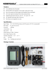
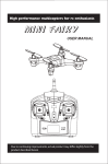
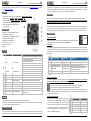
User Manual v1.1
User Manual v1.1
Thank you for purchasing EAGLE series of flight controller. If any difficulties are encountered while setting up or operating this
pins which are marked "RX IN 1-4". When you need to use the 2-axis PTZ camera, connect the rolling and pitch control channels to
board, please consult this manual first. For further help, you may also visit our website at http://www.hobbyeagle.com, or contact us
the pins "RX IN 5-6"; Connect the ESC or servo to the pins marked "PWM OUT" in the correct order, it is according to the selected
via email [email protected].
multi-type refer to the illustration in the last page of this manual. While wiring, please pay attention to the symbol "S + -" beside the
pins, "S" is the signal (white or yellow wire), "+" is VCC (red wire) and "-" is GND (black wire).
Features
Initialization
- Integrated design of 6-axis (3 Gyro+3 Acc ) MEMS sensor for Self-stability and Self-balance;
- 6 Multi-types supported: TRI, QUAD+, QUADX, HEX6+, HEX6X and Y6;
Power on the board, it takes 2-3 seconds to initialize and perform self-calibration while the Blue light keeps flashing rapidly.
- Independent adjustment for Gyro Gain, Stability Gain and Stick Rate (D/R);
Do NOT move the multicopter during initialization or the sensor may not initialize properly. Inaccurate initialization could
- With a 2-axis PTZ camera stabilization system built in;
decrease the performance of the board or even result in complete failure.
- Provides 5-level response rate setting for the sensor;
- One-key setting mode.
Following the initialization, the Blue light will flash several times, the number of flashes indicates the current multi-type selected;
see "Func.2 - Multi-type Selection". When everything is settled, the Blue light will stay on and it is ready for flight. When there is no
Specifications
signal detected, the Red light will keep flashing slowly. In this case, check the connection between the receiver and the board.
Input Voltage: 5 ~ 6V DC ( Provided by BEC of ESC )
Setting Methods
Output PWM Range: 1520 ± 400µs
Frame Rate of PWM Output: 333Hz/ESC, 66Hz/Servo
Entering Setting Mode
Full-Scale Range of Gyro: ±2000dps
Press and hold the button on the board, 2 seconds later both the Blue and Red lights will begin
Full-Scale Range of Accelerometer: ±4g
flashing rapidly, release the button to switch the board into “Setting Mode”.
Operating Temperature: -40 ℃ ~ 85 ℃
Dimensions: 50mm × 50mm
Function List
Weight: 12g
In the setting mode, the Blue and Red lights will flash N times at intervals of 3 seconds(N stands for the number of current function
item). To move to the next item, quickly (less than 2 seconds) press and release the button once, the number of flashes will change
Overview
to reflect this; To select a function, press and hold the button over 2 seconds, release it when both the Blue and Red lights begin
flashing rapidly.
NO.
SHORT NAME
FULL NAME
FUNCTIONS
1: Connects to the Aileron channel
SETTING FUNCTIONS
LED INDICATION
DESCRIPTION
3: Connects to the Throttle channel
NO.
1
Stick Centering
Blue & Red, 1 Flash
Calibrates the center pulse width of signal input
4: Connects to the Rudder channel
2
Multi-type Selection
Blue & Red, 2 Flashes
Selects the current mix-control type
5: Connects to the PTZ camera rolling control channel
3
Response Rate Selection
Blue & Red, 3 Flashes
Sets the response rate for gyro and acc
4
PTZ Setting
Blue & Red, 4 Flashes
5
Exit
Blue & Red, 5 Flashes
2: Connects to the Elevator channel
1
RX IN
6-CH Receiving In
6: Connects to the PTZ camera pitch control channel
Adjusts the compensation ratio and direction for
camera rolling and pitch servos
1 - 6: Connects to the ESC or Servo (M1 - M6)
2
PWM OUT
8-CH ESC/Servo Out
7: Connects to the PTZ camera rolling servo
Exits setting mode and returns to the flight mode
8: Connects to the PTZ camera pitch servo
3
GAIN
Gyro Gain adjust knob
Adjusts the gyro gain, see P3 "Gyro Gain Adjustment"
4
STAB
Stability Gain adjust knob
Adjusts the stability gain, see P3 "Stability Gain Adjustment"
5
D/R
Stick Rate adjust knob
Adjusts the operating rate, see P3 "Stick Rate Adjustment"
This function is for calibrate the center pulse width of reception. To obtain the highest performance it is recommended to
6
IC2
Integrated 6-axis sensor
3-axis gyroscope + 3-axis accelerometer
perform this function after first-time installation or replacing a new radio system. Following the steps below:
7
ENT
Setting Button
For parameter setting
8
LED1
Blue LED indicator
For working or setting status display
9
10
LED2
Forward Direction
Red LED indicator
Forward flight direction
For error report or setting status display
Aligns the white arrow with forward flight direction when
mounting the board
Func.1 - Stick Centering
Step 1
Connect the receiver to the board by the corresponding channel first;
Step 2
Turn on the transmitter, put the trimming buttons to the center position, reset the Sub-trim parameters to 0;
Step 3
Power on the board, enter setting mode after initialization and select the stick centering function;
Step 4
The Blue light will begin flashing rapidly for about 3 seconds which indicates that the board is calibrating signals. Don't
move the sticks during this process. The Blue light will flash once again after 1 second and the board will return to the Function List
automatically after calibration done.
Func.2 - Multi-type Selection
Attentions
This function is used to select mix-control type of your multicopter.
NO.
SETTINGS
LED INDICATION
1. In order to make the best out of your board, please read this manual carefully ahead;
The Blue light will flash N times at intervals of 3 seconds (N stands
1
TRI Copter (Y3)
Blue, 1 Flash
2. Exam if your multicopter has been well installed before installation. To obtain the best performance, it is recommended to use a
for the number of multi-type selected). To move to the next type,
2
QUAD+ Copter
quickly press and release the button once, the times of flash will
3
QUADX Copter
change to reflect this. Hold the button until both the Blue and Red
4
HEX6+ Copter
Blue, 4 Flashes
lights begin flashing rapidly to save changes and return to the
5
HEX6X Copter
Blue, 5 Flashes
6
Y6 Copter
Blue, 6 Flashes
high-precision, good-quality fuselage and equipment.
Installation & Wiring
Use 4 screws (Φ3mm) to firmly fix the board in the center of your multicopter. Please align the white arrow with forward flight
Function List.
( * is the default setting )
Blue, 2 Flashes
*
Blue, 3 Flashes
direction when mounting. After installation, connect the channels of Aileron, Elevator, Throttle and Rudder from your receiver to the
http://www.hobbyeagle.com
1/4
[email protected]
http://www.hobbyeagle.com
2/4
[email protected]
User Manual v1.1
User Manual v1.1
Func.3 - Response Rate Selection
This function is to choose the response rate for gyroscope and
NO.
SETTINGS
LED INDICATION
accelerometer. The Blue light will flash N times at intervals of 3
1
Level - 1
(Fastest)
Blue, 1 Flash
seconds (N stands for the number of level selected). The default
2
Level - 2
(Fast) *
Blue, 2 Flashes
setting "Level-2" is accepted for most multicopters. We recommend
3
Level - 3
(Standard)
Blue, 3 Flashes
you to try this setting first. On high precision copter with high
4
Level - 4
(Slow)
Blue, 4 Flashes
performance and small vibration, "Level-1" may work better. The
5
Level - 5
(Slowest)
Blue, 5 Flashes
Step 1
Connect your receiver, ESC and motors to the board by the corresponding channel first;
Step 2
Turn on the transmitter, move the throttle stick to the top position;
Step 3
Power on the board, the Red light will begin flashing rapidly. Move the throttle stick to the bottom when the sounds "Beep,
Beep~" of throttle range highest point has been confirmed. The Red light will turn off while moving the throttle stick down. Specific
construction shall be referred to the manual of your ESC;
Step 4
The board will exit this function automatically after waiting for about 5 seconds, keep the throttle stick at the bottom.
ESC or Servo Connections
"Level-5" may work better on larger and heavier copters. To switch
between different levels, quickly press and release the button, the times of flash will change to reflect this. Hold the button until both
the Blue and Red lights begin flashing rapidly to save changes and return to the Function List.
Func.4 - PTZ Setting
A 2-axis PTZ camera stabilization system has been built in the board, the compensation ratio and direction of the rolling and pitch
servos can be adjusted through this function. The value of ratio can be from -50 to +50, "+/-" represents the positive and negative
direction, “0” is the factory default setting (without compensation).
Switching Channels
After entering this function, the Blue light will flash once indicates that the rolling has been selected for
the current setting channel initially, to switch to the pitch channel, quickly press and release the button once. The Blue light will
flashes twice to reflect this. Before adjusting, you have to choose the corresponding channel first.
Adjusting Methods
Move the aileron stick to the right or left to
increase or decrease the ratio for rolling servo, and move the elevator
stick to the up or down to increase or decrease the ratio for pitch servo.
If holding the stick, the value will keep increasing or decreasing until
the maximum or minimum been reached. The lights will keep flashing
in different ways and color while the parameter is increasing or
decreasing, refer to the table on the right. You can pick the multicopter
LED INDICATION
DESCRIPTION
Blue, 1 Flash
Increase of 1
Red, 1 Flash
Decrease of 1
lights begin flashing rapidly, release it to save changes and return to
Blue, very rapid flashing
Maximum of +50 reached
the Function List after adjusting.
Red, very rapid flashing
Minimum of -50 reached
up and rotate it to a certain angle to check whether the compensation
angle is suitable.
Exit Saving Changes
Hold the button until both the Blue and Red
Func.5 - Exiting Setting Mode
Once you have completed setting up the parameters, select this item to get back to the flight mode. For your safety, please make
sure that the throttle stick is in the lowest before exiting or the Red light will not stop flashing rapidly until you put the stick down.
Gyro Gain Adjustment
The [GAIN] knob is used to adjust the gyro gain for pitch, roll and yaw, clockwise for increase, anticlockwise for
decrease. The default setting 50% is acceptable for most multicopters. You need to fine tune it in order to get
the best result during the flight.
Stability Gain Adjustment
The [STAB] knob is for adjusting the stability gain, clockwise for increase, anticlockwise for decrease. The greater the volume the
faster the copter trying to level horizontally when the sticks are released, and vice versa. To get the best effect of self-stability, it
should be adjusted together with the [GAIN] knob. Tips: The self-stability function will be disabled if you turn [STAB] to 0%..
Stick Rate (D/R) Adjustments
The [D/R] knob is used to adjust the operating rate for aileron, elevator and rudder sticks, clockwise for increase, anticlockwise for
decrease. The default setting 50% will satisfy most beginners. Increase it if you would like the multicopter to be operated more
flexible, and vice versa.
Throttle Range Calibration
This function is used to setup the throttle range for your ESC. To obtain the best throttle linearity it is recommended to perform
this function after first-time installation or replacing new ESC. Following the steps below:
http://www.hobbyeagle.com
3/4
[email protected]
http://www.hobbyeagle.com
4/4
[email protected]