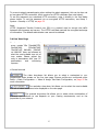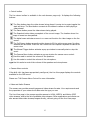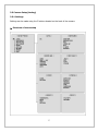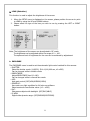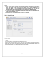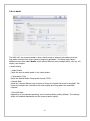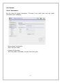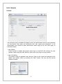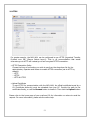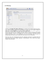
1
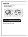
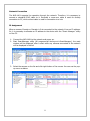
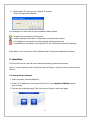
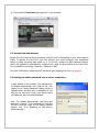
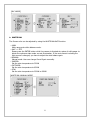
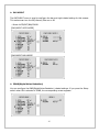
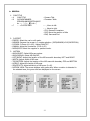
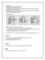
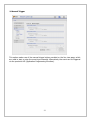
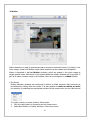
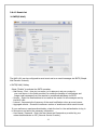
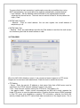
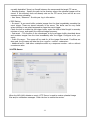
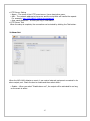
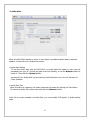
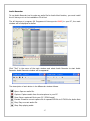
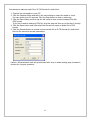
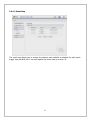
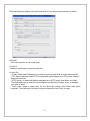
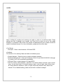
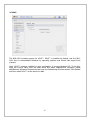
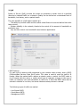
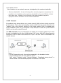
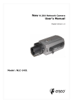
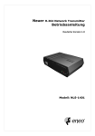
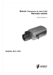
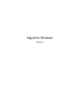
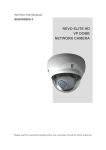
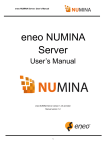
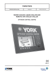
VP Dome Network Camera
User’s Manual
English Version 1.0
Model : NLD-1401
2
WARNING
RISK OF ELECTRIC SHOCK
DO NOT OPEN
WARNING: TO REDUCE THE RISK OF ELECTRIC SHOCK,
DO NOT REMOVE COVER (OR BACK).
NO USER-SERVICEABLE PARTS INSIDE.
REFER SERVICING TO QUALIFIED
SERVICE PERSONNEL.
The lightning flash with arrowhead symbol, within an equilateral triangle, is intended to
alert the user to the presence of uninsulated "dangerous voltage" within the product’s
enclosure that may be of sufficient magnitude to constitute a risk of electric shock.
The exclamation point within an equilateral triangle is intended to alert the user to the
presence of important operating and maintenance (servicing) instructions in the literature
accompanying the appliance.
CE COMPLIANCE STATEMENT
COMPLIANCE NOTICE OF FCC:
THIS EQUIPMENT HAS BEEN TESTED AND FOUND TO COMPLY WITH THE LIMITS FOR A CLASS A
DIGITAL DEVICE, PURSUANT TO PART 15 OF THE FCC RULES. THESE LIMITS ARE DESIGNED TO
PROVIDE REASONABLE PROTECTION AGAINST HARMFUL INTERFERENCE WHEN THE EQUIPMENT
IS OPERATED IN A COMMERCIAL ENVIRONMENT. THIS EQUIPMENT GENERATES, USES, AND CAN
RADIATE RADIO FREQUENCY ENERGY AND IF NOT INSTALLED AND USED IN ACCORDANCE WITH
THE INSTRUCTION MANUAL, MAY CAUSE HARMFUL INTERFERENCE TO RADIO COMMUNICATIONS.
OPERATION OF THIS EQUIPMENT IN A RESIDENTIAL AREA IS LIKELY TO CAUSE HARMFUL
INTERFERENCE, IN WHICH CASE USERS WILL BE REQUIRED TO CORRECT THE INTERFERENCE AT
THEIR OWN EXPENSE.
WARNING:
CHANGES
OR
MODIFICATIONS
NOT
EXPRESSLY
APPROVED
BY
THE
PARTY
RESPONSIBLE FOR COMPLIANCE COULD VOID THE USER’S AUTHORITY TO OPERATE THE
EQUIPMENT.
THIS CLASS OF DIGITAL APPARATUS MEETS ALL
INTERFERENCE-CAUSING EQUIPMENT REGULATIONS.
REQUIREMENTS
OF
THE
CANADIAN
The information in this manual is believed to be accurate as of the date of publication. The seller is not responsible
for any problems resulting from the use thereof. The information contained herein is subject to change without
notice. Revisions or new editions to this publication may be issued to incorporate such changes.
3
Important Safeguard
1. Read Instructions
All the safety and operating instructions should be read before the
appliance is operated.
2. Retain Instructions
The safety and operating instructions should be retained for future
reference.
3. Cleaning
Unplug this equipment from the wall outlet before cleaning it. Do
not use liquid aerosol cleaners. Use a damp soft cloth for cleaning.
4. Attachments
Never add any attachments and/or equipment without the approval of
the manufacturer as such additions may result in the risk of fire,
electric shock or other personal injury.
5. Water and/or Moisture
Do not use this equipment near water or in contact with water.
6. Accessories
Do not place this equipment on an unstable cart, stand or table. The
equipment may fall, causing serious injury to a child or adult, and
serious damage to the equipment. Wall or shelf mounting should
follow the manufacturer's instructions, and should use a mounting kit
approved by the manufacturer.
13. Damage requiring Service
Unplug this equipment from the wall outlet and refer servicing to
qualified service personnel under the following conditions:
A. When the power-supply cord or the plug has been damaged.
B. If liquid is spilled, or objects have fallen into the equipment.
C. If the equipment has been exposed to rain or water.
D. If the equipment does not operate normally by following the
operating instructions, adjust only those controls that are covered
by the operating instructions as an improper adjustment of other
controls may result in damage and will often require extensive
work by a qualified technician to restore the equipment to its
normal operation.
E. If the equipment has been dropped, or the cabinet damaged.
F. When the equipment exhibits a distinct change in performance —
this indicates a need for service.
14. Replacement Parts
When replacement parts are required, be sure the service technician
has used replacement parts specified by the manufacturer or that have
the same characteristics as the original part.
Unauthorized
substitutions may result in fire, electric shock or other hazards.
15. Safety Check
Upon completion of any service or repairs to this equipment, ask the
service technician to perform safety checks to determine that the
equipment is in proper operating condition.
16. Field Installation
This installation should be made by a qualified service person and
should conform to all local codes.
17. Correct Batteries
Warning: Risk of explosion if battery is replaced by an incorrect type.
Dispose of used batteries according to the instructions.
This equipment and cart combination should be moved with care.
Quick stops, excessive force, and uneven surfaces may cause the
equipment and cart combination to overturn.
7. Power Sources
This equipment should be operated only from the type of power
source indicated on the marking label. If you are not sure of the type
of power, please consult your equipment dealer or local power
company.
8. Power Cords
Operator or installer must remove power and TNT connections before
handling the equipment.
9. Lightning
For added protection for this equipment during a lightning storm, or
when it is left unattended and unused for long periods of time, unplug
it from the wall outlet and disconnect the antenna or cable system.
This will prevent damage to the equipment due to lightning and
power-line surges.
10. Overloading
Do not overload wall outlets and extension cords as this can result in
the risk of fire or electric shock.
11. Objects and Liquids
Never push objects of any kind through openings of this equipment as
they may touch dangerous voltage points or short out parts that could
result in a fire or electric shock. Never spill liquid of any kind on
the equipment.
12. Servicing
Do not attempt to service this equipment yourself.
servicing to qualified service personnel.
Refer all
4
18. Tmra
A manufacturer’s maximum recommended ambient temperature
(Tmra) for the equipment must be specified so that the customer and
installer may determine a suitable maximum operating environment
for the equipment.
19. Elevated Operating Ambient Temperature
If installed in a closed or multi-unit rack assembly, the operating
ambient temperature of the rack environment may be greater than
room ambient.
Therefore, consideration should be given to
installing the equipment in an environment compatible with the
manufacturer’s maximum rated ambient temperature (Tmra).
20. Reduced Air Flow
Installation of the equipment in the rack should be such that the
amount of airflow required for safe operation of the equipment is not
compromised.
21. Mechanical Loading
Mounting of the equipment in the rack should be such that a
hazardous condition is not caused by uneven mechanical loading.
22. Circuit Overloading
Consideration should be given to connection of the equipment to
supply circuit and the effect that overloading of circuits might have
on over current protection and supply wiring.
Appropriate
consideration of equipment nameplate ratings should be used when
addressing this concern.
23. Reliable Earthing (Grounding)
Reliable grounding of rack mounted equipment should be maintained.
Particular attention should be given to supply connections other than
direct connections to the branch circuit (e.g., use of power strips).
Table of Contents
1. Product Description…………………………………………………………………………………………………6
2. Installation……………………………………………………..........................…………..……………….8
3. Operation…………………………………………………………………………………………………………….13
3.1 Access from a browser …………………………………………………………………………………..13
3.2 Access from the internet ………………………………………………………………………………..14
3.3 Setting the admin password over a secure connection…………………………….…….…14
3.4 Live View Page ………………………………………………………………………………………………15
3.5 Camera Setup (Analog)……………………………………………………………………………….….17
3.5.1 Settings…………………………………………………………………………………………………..17
3.5.2 Lens Adjustment (Optical Vari-focal Lens)…………………………………………………..23
3.6 Network Camera Setup………………………………………………………………………………...24
3.6.1 Basic Configuration…………………………………………………………………….…………...25
3.6.1.1 Users…………………………………………………………………………………….………...25
3.6.1.2 Network……………………………………………………………………………….…………...26
3.6.1.3 Video & Image..……………………………………………….……………………………...27
3.6.1.4 Audio..…..……………………………………………………….…………………………….....30
3.6.1.5 Date & Time..……………………………………………………………………….………...32
3.6.2 Video & Image..……………..……………………………………………………………………....33
3.6.3 Audio..……………………………….………………………………………………………………....36
3.6.4 Event………………………………………………………………………………………………………37
3.6.4.1 Event-In…………………………………………………………………………………………….37
3.6.4.2 Event-Out………………………………………………………………………………………….42
3.6.4.3 Event Map…………………………………………………………………………………………49
3.6.5 System……………………………………………………………………………………….………...51
3.6.5.1 Information………………………………………………………….…………………………...51
3.6.5.2 Security..…………………………………………………………….…………………………...52
3.6.5.3 Date & Time..…………………………………………………………………….…………...55
3.6.5.4 Network..……………………………………………………………………….……………....56
3.6.5.5 Language..……………….…………………………………….……………………………....63
3.6.5.6 Maintenance..……………..………………………………….…..........................…....64
3.6.5.7 Support............……………………………………….........................….…………....65
3.7 About……………..………………………..…………………………………………………….…………....66
3.8 camera Menu Control.……….……..…………………………………………………….…………....66
3.9 Help…………………………………………….……………………………………………………………....67
3.10 Resetting to the factory default settings……………….……………………………………....68
4. Appendix ……………………………………………………………..……………………………………….……69
4.1. Troubleshooting.…………………………..……………………………………………………….……69
4.2. Preventive Maintenance..………………………..........................….…………………….……69
4.3. Product Specification…..………………………………………………………………..….….....……70
5
1. Product Description
This manual applies to the Network Camera – NLD-1401.
The NLD-1401 vandal resistant dome is a Hybrid analogue and IP camera. It has a standard
composite BNC out put allowing it to be connected via coax to a traditional coax based
CCTV system, as well as being connected to an IP based system.
The NLD-1401 comes supplied with its own viewing software which allows the user to View,
record and configure the camera. Viewing and configuration can also be carried out via a
web browser such as Internet Explorer.
The camera can transmit real time full frame rate video in H.264, MJPEG or MPEG4
compression formats.
The alarm input and alarm output can be used to connect various third party devices, such
as, door sensors and alarm bells.
Components
The system comes with the following components:
NLD-1401
Installation CD
Installation Guide
Note: Check your package to make sure that you received the complete system, including
all components shown above.
6
Key Features
• Brilliant video quality
The NLD-1401 offers the highly efficient H.264 video compression, which drastically
reduces bandwidth and storage requirements without compromising image quality. Motion
JPEG is also supported for increased flexibility.
• Dual streams
The NLD-1401 can deliver dual video streams simultaneously at full frame rate in all
resolutions up to D1 (720x480 in NTSC, 720x576 in PAL) using Motion JPEG and H.264 (or
MPEG-4). This means that several video streams can be configured with different
compression formats, resolutions and frame rates for different needs.
• Image setting adjustment
The NLD-1401 also enables users to adjust image settings such as contrast, brightness and
saturation to improve images before encoding takes place.
• Intelligent video capabilities
The NLD-1401 includes intelligent capabilities such as enhanced video motion detection.
The encoder’s external inputs and outputs can be connected to devices such as sensors and
relays, enabling the system to react to alarms and activate lights or open/close doors.
• Power over Ethernet
Support for Power over Ethernet (IEEE802.3af) enables the unit, as well as the analog
camera that is connected to it, to receive power through the same cable as for data
transmission. This makes for easy installation since no power outlet is needed.
• Audio support
The NLD-1401 also supports two-way audio.
• Improved Security
The NLD-1401 logs all user access, and lists currently connected users. Also, its full frame
rate video can be provided over HTTPS.
• Camera
-. Superior image quality (560 TV Lines).
-. 0.3 Lux (Color) @ F1.2 Sensitivity.
-. C/CS, backfocus cam for easy adjustment.
-. Auto electronic shutter [1/60(1/50) ~ 1/100,000] and manual electronic shutter modes.
-. Full control via the OSD menu key on the side of the camera.
-. Auto and manual white balance modes.
-. BLC (Back Light Compensation)
-. Day&Night (Auto / Color / B/W)
-. AGC (Auto Gain Control)
-. Incredible noise reduction for picture quality & file size.
-. Sens-up (x2 ~ x128)
-. Privacy Zone 8 points.
-. MIRROR
-. VIDEO OUT(BNC)
7
2. Installation
For the operation of the NLD-1401, it is necessary to connect a network cable for data
transmission, power connection from supplied power adapter and connect a general analog
camera. Depending on operation methods, it is possible to connect an alarm cable or audio
cable additionally. For its fixation on different locations, please consult with an installer.
Overview
• Top View
NO
1
2
Name
Lens
Extension Cable
Description
Allows wide area to be monitored
26pin camera extension cable
• Extension Cable
8
NO
1
2
3
Wire Color
Red: AC24V/DC12V
White: AC24V/GND
Green: AC24V/DC12V
Black: AC24V/GND
Pink: Alarm In
Yellowish Green: GND
Yellow: AD Key
Brown: GND
Light Blue: Alarm Out
Gray: GND
Description
Main Power, 2pin terminal, DC12V/AC24V, max. 6.5W
Heater Power, 2pin terminal, max. 10Watt @ DC12V,
max. 20Watt @ AC24V
Alarm Input, AD Key Input, Alarm Output:
6pin terminal.
Gray
Ethernet, RJ-45 port compatible with 10/100Mbps PoE.
Modular Jack
Video Composite Output, BNC Jack
Audio line output, Stereo Jack
Black
Audio line input, Stereo Jack
4
Black
5
6
7
Black
Caution: Never aim the camera directly into the sun.
Base Installation
1. Make mounting holes and cable hole in the place (ceiling) to which this dome camera
is installed using the supplied template sheet.
Warning: The total mass of the main unit is approx 1.3kg. Check whether the ceiling
to which the Dome Camera is installed is strong enough to hold the unit mass. If not,
the Dome Camera could fall, causing injury.
2. Attach the safety wire for securing the dome camera to ceiling or structure not to fall.
9
3. Extract each wire through the cable hole, connect BNC cable and communication lines.
4. Unlock torx screws (4x) the dome cover and fix the dome case firmly with supplied
mounting screws (4x), plastic anchors (4x), O-Rings (4x).
5. Adjust desired focus and scene by turning and moving the hemisphere by hand.
6. Lock the housing cover with torx screws (4x).
• Cable through the electrical box with the dome base
The housing can also be mounted on a 4s or 2s electrical box.
• Using the conduit knockout punched with the dome base
Remove the conduit knockout punched for the cable entry.
10
Heater Kit Installation
1. Place the heater element is slot “A”. Please ensure that the cables are facing upwards
and the heater is pointing towards the Dome.
2. Place the PCB in slot “B”. Please ensure that the PCB is facing inside of the Dome with
the connection blocks at the top.
3. Place the plug in the Socket “C” (J3) which is found on the controller board.
• Cheater (IF Applicable)
Power Supply
Power Consumption
Heater On
Heater Off
24VAC
20Watt
12DCV
10Watt
at 41°F (5°C)
at 59°F (15°C)
• Power
Use Certified/Listed Class 2 power source only.
11
Network Connection
The NLD-1401 supports the operation through the network. Therefore, it is necessary to
connect a standard RJ-45 cable to it. Generally a cross-over cable is used for directly
connection to PC, while a direct cable is used for connection to a hub.
IP Assignment
When a camera, Encoder or Decoder is first connected to the network it has no IP address.
So, it is necessary to allocate an IP address to the device with the “Smart Manager” utility
on the CD.
1. Connect the NLD-1401 to the network and power up.
2. Start SmartManager utility (All programs>NT-Manager16>SmartManager), the main
window will be displayed, after a short while any cameras connected to the network
will be displayed in the list.
3. Select the camera on the list and click right button of the mouse. You can see the popup menu as below.
12
4. Select Assign IP. You cam see a Assign IP window.
Enter the required IP address.
The description of each field for the connection status follows.
: Available for connection to the camera
: Loading settings information of video after connecting the camera.
: Connectable to the camera but fixed security settings (password)
: Unavailable for connection to the camera (PC can not access relevant IP Address)
Note: Refer to NT-Manager16 Client Software User’s Manual for detailed information.
3. Operation
The NLD-1401 can be used with most standard operating systems and browsers.
Notes: To view streaming video in Microsoft Internet Explorer, set your browser to allow ActiveX
controls.
3.1 Access from a browser
1. Start a browser (Internet Explorer).
2. Enter the IP address or host name of NLD-1401 in the Location/Address field of
your browser.
3. You can see a starting page. Click Live View or Setup to enter web page.
13
4. The encoder’s Live View page appears in your browser.
3.2. Access from the internet
Access from the internet Once connected, the NLD-1401 is accessible on your local network
(LAN). To access the NLD-1401 from the Internet you must configure your broadband
router to allow incoming data traffic to it. To do this, enable the NAT-traversal feature,
which will attempt to automatically configure the router to allow access to the NLD-1401.
This is enabled from Setup > System > Network > NAT.
For more information, please see NAT traversal (port mapping) for IPv4, on page 62.
3.3 Setting the admin password over a secure connection
To gain access to the product, the password for
the default administrator user must be set. This
is done in the “Admin Password” dialog, which is
displayed when the NLD-1401 is accessed for the
setup at the first time. Enter your admin name
and password, set by the administrator.
Note: The default administrator username and
password is “admin”. If the password is lost, the
NLD-1401 must be reset to the factory default
settings. See “3.10 Resetting to the factory
default settings”.
14
To prevent network eavesdropping when setting the admin password, this can be done via
an encrypted HTTPS connection, which requires an HTTPS certificate (see note below).
To set the password via a standard HTTP connection, enter it directly in the first dialog
shown below. To set the password via an encrypted HTTPS connection, see Setup >
System > Secutity > HTTPS, on page 53.
Note:
HTTPS (Hypertext Transfer Protocol over SSL) is a protocol used to encrypt the traffic
between web browsers and servers. The HTTPS certificate controls the encrypted exchange
of information. The default administrator user cannot be deleted.
3.4 Live View Page
The live view page comes in eight
screen modes like 704x480(576),
704x240(288),
352x240(288),
176x120(144), 640x480, 320x240,
and 160x120. Users are allowed to
select the most suitable one out of
those modes. Please, adjust the
mode in accordance with your PC
specifications
and
monitoring
purposes.
• General controls
The video drop-down list allows you to select a customized or preprogrammed video stream on the live view page. Stream profiles are configured under
Setup > Basic Configuration > Video & Image. See Basic Configuration, on page 25 for
more information.
The resolution drop-down list allows you to select the most suitable
one out of video resolutions to be displayed on live view page.
The protocol drop-down list allows you to select which combination of
protocols and methods to use depends on your viewing requirements, and on the
properties of your network.
15
• Control toolbar
The live viewer toolbar is available in the web browser page only. It displays the following
buttons:
The Stop button stops the video stream being played. Pressing the key again toggles the
start and stop. The Start button connects to the network camera or start playing a
video stream.
The Pause button pause the video stream being played.
The Snapshot button takes a snapshot of the current image. The location where the
image is saved can be specified.
The digital zoom activates a zoom-in or zoom-out function for video image on the live
screen.
The Full Screen button causes the video image to fill the entire screen area. No other
windows will be visible. Press the 'Esc' button on the computer keyboard to cancel full
screen view.
The Manual Trigger button activates a pop-up window to manually start or stop the
event.
The Camera Menu button activates a pop-up window for camera menu control.
Use this scale to control the volume of the speakers.
Use this scale to control the volume of the microphone.
Use this scale to control the volume of the speakers and microphones.
• Camera Menu controls
If the NLD-1401 has been appropriately configured, the Live View page displays the controls
available for the OSD menu.
Please see “3.8 Camera Menu Control for more information.
• Video and Audio Streams
The camera can provide several images and video stream formats. Your requirements and
the properties of your network will determine the type you use.
The Live View page in the camera provides access to H.264, MPEG-4 and Motion JPEG
video streams, and to the list of available video streams. Other applications and clients can
also access these video streams/images directly, without going via the Live View page.
16
3.5 Camera Setup (Analog)
3.5.1 Settings
Settings can be made using the 5 buttons located on the back of the camera.
▶ Structure of menu setup
17
▶ LENS (Selection)
This function is used to adjust the brightness of the screen.
1. When the SETUP menu is displayed on the screen, please position the arrow to point
to LENS by using the UP and DOWN buttons.
2. Please select the type of the lens you wish to use by pressing the LEFT or RIGHT
button.
Note: The brightness of the screen can be adjusted in DC mode.
The brightness can be adjusted within the range of 0 ~ 100.
The optimum level of brightness for the user can be achieved by adjustment.
▶ EXPOSURE
The EXPOSURE menu is used to set the automatic light control method for this camera.
-. SHUTTER:
Select the shutter mode. (1/60(50), FLK~1/100,000 sec, x2~x256)
Can be changed while in shutter mode.
-. BRIGHTNESS:
Adjust BRIGHTNESS level (0~100).
Can be changed while in manual lens mode.
-. AGC:
Auto gain control (OFF/LOW/MIDDLE/HIGH)
-. SENSE-UP:
Use under very light condition for full color surveillance.
Select maximum Low-Shutter value. (x2 ~ x256)
-. BLC:
Sharpness subjects with backlight. (OFF/BLC/HBLC)
-. D-WDR:
Digital wide dynamic range. (OFF/INDOOR/OUTDOOR)
18
[BLC MODE]
▶ WHITE BAL
The Screen color can be adjusted by using the WHITE BALANCE function.
-. AWB:
Wide range auto white balance mode.
-. AWC => SET:
Please press the ENTER button while the camera is directed at a piece of while paper to
obtain the optimum state under current illumination. If the environment including the
light source is changed, you have to adjust the wide balance gain.
-. MANUAL:
Manual mode. User can change R and B gain manually.
-. INDOOR:
Set the color temperature to 3200K
-. OUTDOOR:
Set the color temperature to 6300K
-. ATW:
Set the color temperature to 2500K to 9500K
[WHITE BAL MANUAL MODE]
19
▶ DAY NIGHT
The DAT/NIGHT menu is used to configure the day and night related setting for this camera.
This camera can turn the IR(Infrared) filter on or off.
-. Mode: AUTO/EXT/BW/COLOR
[DAY/NIGHT AUTO MODE]
[DAY/NIGHT B/W MODE]
▶ 3DNR(Digital Noise Reduction)
You can configure the DNR(Digital Noise Reduction) related settings. If you press the Setup
switch when ON is selected in 3DNR, the corresponding screen appears.
20
▶ SPECIAL
1. CAM TITLE
-. A
CAM TITLE
-. B
0123456789ABCD
EFGHIJKLMNOPQRSTUVWXYZ
▶→←↑↓()−_▐ /=&:~,”
-. C
←→CLR POS END
: Camera Title
: Character Table
: ←, Move to left
:→, Move to right
: CLR, Erase all characters
: POS, Move the position of title
: END, Save and End
2.
-.
-.
-.
-.
-.
D-EFFECT
FREEZE: Select the real or still mode.
MIRROR: Reverse the screen in 3 modes selection. (OFF/MIRROR/V FLIP/ROTATION)
D-ZOOM: D-Zoom (x2~x32) / Adjust PAN/TILT
GAMMA: Adjust the luminance. (0.05~1.00)
NEGA/POSI: Select the negative or positive mode.
3.
-.
-.
-.
-.
-.
-.
-.
-.
MOTION
AREA SELECT: Select MD area number.
AREA DISPLAY: Select MD ON/OFF.
LEFT/RIGHT: Adjust the location of the MD area with boundary LEFT and RIGHT.
WIDTH: Adjust width of MD area.
TOP/BOTTOM: Adjust the location of the MD area with boundary TOP and BOTTOM
HEIGHT: Adjust the height of MD area.
SENSITIVITY: Adjust sensitivity of MD area. (0~40)
MOTION VIEW: The screen displays with green dots. When a motion is detected in
the selected area, the green dots are displayed on the screen.
21
4.
-.
-.
-.
-.
-.
-.
-.
PRIVACY
AREA SELECT: Select MAK area number.
AREA DISPLAY: Select MASK ON/OFF.
LEFT/RIGHT: Adjust the location of the MASK area with boundary LEFT and RIGHT.
WIDTH: Adjust width of MASK area.
TOP/BOTTOM: Adjust the location of the MASK area with boundary TOP and BOTTOM.
HEIGHT: Adjust the height of MASK area.
COLOR: Select MASK color. (0~15)
[PRIVACY MODE]
5. SYNC: Select Internal or Line Lock mode.
-. INT: This mode is necessary for using the internal synchronization.
-. L/L: This mode is necessary for the operation of multi camera because it synchronizes
the camera phase by using the external signal (AC Signal).
-. PAHSE: Sync phase is adjustable in line lock mode.
6. LANGUAGE : You can change the OSD language using the LEF/RIGHT Setup switch.
▶ ADJUST
1. SHARPNESS: Can be adjusted SHARPNESS of outlines. (0~31)
2. BLUE: Adjust B-GAIN value. (0~100)
3. RED: Adjust R-GAIN value. (0~100)
▶ PRESET
1. FACTORY: Returns to the level which was set by the manufacturer.
▶ EXIT
1. EXIT: Saves all the setting menus and then exits.
22
3.5.2 Lens Adjustment (Optical Vari-focal Lens)
Field of view: Adjust setting from Telephoto (T) to wide (W) field of view.
Focus: Adjust lens focus from near (N) to infinity (∞).
DC Auto IRIS Lens
Lens Type
2.6 ~ 6mm
1/3” CCD
Image Size
Focal Length 2.6~6mm±5%
Aperture
1 : 1.6 ± 5%
Ratio
DIAGONAL
Angular
Field of View
2.6mm: 134.6◦
◦
6.0mm: 59.2
4 ~ 9mm
2.8 ~ 12mm
6 ~ 50mm
1/3” CCD
4~9mm±5%
1/3” CCD
2.8~12mm±5%
1/3” CCD
6.0~50mm±5%
1 : 1.6 ± 5%
1 : 1.4 ± 5%
1 : 1.6 ± 5%
DIAGONAL
4.0mm: 92.4◦
◦
9.0mm: 39.2
23
2.8mm: 119.9◦
◦
12mm: 28.8
DIAGONAL
6.0mm: 58.6◦
◦
50mm: 7.1
3.6 NLD-1401 Setup
This section describes how to configure the NLD-1401, and is intended for product
Administrators, who have unrestricted access to all the Setup tools; and Operators, who
have access to the settings for Basic, Live View, Video & Image, Audio, Event, and System
Configuration.
You can configure the NLD-1401 by clicking Setup in the top right-hand corner of the Live
View page. Click on this page to access the online help that explains the setup tools.
When accessing the NLD-1401 for the first time, the “Admin Password” dialog appears.
Enter your admin name and password, set by the administrator.
If the password is lost, the NLD-1401 must be reset to the factory default settings. See
“3.10 Resetting to the Factory Default Settings.
24
3.6.1 Basic Configuration
3.6.1.1 Users
User access control is enabled by default. An administrator can set up other users, by giving
these user names and passwords. It is also possible to allow anonymous viewer login,
which means that anybody may access the Live View page, as described below:
The user list displays the authorized users and user groups (levels):
User Group
Guest
Operator
Administrator
Authority
Provides the lowest level of access, which only allows access to the
Live View page.
An operator can view the Live View page, create and modify
events, and adjust certain other settings. Operators have no access
to System Options.
An administrator has unrestricted access to the Setup tools and can
determine the registration of all other users.
• Enable anonymous viewer login: Check the box to use the webcasting features. Refer to
“3.6.2 Video & Image” for more details.
25
3.6.1.2 Network
The NLD-1401 support both IP version 4 and IP version 6. Both versions may be enabled
simultaneously, and at least one version must always be enabled. When using IPv4, the IP
address for the video encoder can be set automatically via DHCP, or a static IP address can
be set manually. If IPv6 is enabled, the NLD-1401 receive an IP address according to the
configuration in the network router. There is also the option of using the Internet Dynamic
DNS Service. For more information on setting the Network, please see Setup>
System>Security>Network.
• IPv4 Address Configuration - Check this box to enable IPv4.
• Obtain IP address via DHCP - Dynamic Host Configuration Protocol (DHCP) is a protocol
that lets network administrators centrally manage and automate the assignment of IP
addresses on a network. DHCP is enabled by default. Although a DHCP server is mostly
used to set an IP address dynamically, it is also possible to use it to set a static, known IP
address for a particular MAC address.
• Use the following IP address - To use a static IP address for the NLD-1401, check the
radio button and then make the following settings:
-. IP address - Specify a unique IP address for your NLD-1401. (To check if the IP
address you intend to use is available or not, click the Test button)
-. Subnet mask - Specify the mask for the subnet the NLD-1401 is located on.
-. Default router - Specify the IP address of the default router (gateway) used for
connecting devices attached to different networks and network segments.
26
Notes:
1. DHCP should only be enabled if using dynamic IP address notification, or if your DHCP
server can update a DNS server, which then allows you to access the NLD-1401 by
name (host name). If DHCP is enabled and you cannot access the unit, you may have
to reset it to the factory default settings and then perform the installation again.
2. The ARP/Ping service is automatically disabled two minutes after the unit is started, or
as soon as an IP address is set.
3. Pinging the unit is still possible when this service is disabled.
3.6.1.3 Video & Image
• Video Setting
-. Codec
The codec settings are separated into MPEG4 and H.264.
H.264 is also known as MPEG-4 Part 10. This is the new generation compression standard for
digital video. This function offers higher video resolution than Motion JPEG or MPEG-4 at the same
bit rate and bandwidth, or the same quality video at a lower bit rate.
27
-. Profile
There are 4 pre-programmed stream profiles available for quick set-up.
Choose the form of video encoding you wish to use from the drop-down list:
* H.264 MP(Main Profile):
Primarily for low-cost applications that requires additional error robustness, this profile
is used rarely in videoconferencing and mobile applications, it does add additional error
resilience tools to the Constrained Baseline Profile. The importance of this profile is
fading after the Constrained Baseline Profile has been defined.
* H.264 BP(Base Profile):
Originally intended as the mainstream consumer profile for broadcast and storage
applications, the importance of this profile faded when the High profile was developed
for those applications.
* MPEG4 SP(Simple Profile) is mostly aimed for use in situations where low bit rate and
low resolution are mandated by other conditions of the applications, like network
bandwidth, device size etc.
* MPEG4 ASP(Advanced Simple Profile)'s notable technical features relative to the Simple
Profile, which is roughly similar to H.263, including "MPEG"-style quantization,
interlaced video, B pictures (also known as B Frames), Quarter Pixel motion
compensation (Qpel), Global motion compensation (GMC).
-. Resolution
It enables users to determine a basic screen size when having an access through the Web
Browser or PC
program. The screen size control comes in seven modes like
4CIF(704x480(576)), 2CIF(704x240(288)), CIF
(352x240(288)), QCIF(176x120(144)),
VGA(640x480), QVGA(320x240), and QQVGA(160x120). Users can reset the selected
screen size anytime while monitoring the screen on a real-time basis.
-. Bit-rate control
Limiting the maximum bit rate helps control the bandwidth used by the H.264 or MPEG-4
video stream. Leaving the Maximum bit rate as unlimited maintains consistently good
image quality but increases bandwidth usage when there is more activity in the image.
Limiting the bit rate to a defined value prevents excessive bandwidth usage, but images
are lost when the limit is exceeded.
Note that the maximum bit rate can be used for both variable and constant bit rates.
The bit rate can be set as Variable Bit Rate (VBR) or Constant Bit Rate (CBR). VBR
adjusts the bit rate according to the image complexity, using up bandwidth for increased
activity in the image, and less for lower activity in the monitored area.
CBR allows you to set a fixed target bitrate that consumes a predictable amount of
bandwidth. As the bit rate would usually need to increase for increased image activity,
but in this case cannot, the frame rate and image quality are affected negatively. To
partly compensate for this, it is possible to prioritize either the frame rate or the image
quality whenever the bit rate needs to be increased. Not setting a priority means the
frame rate and image quality are equally affected.
28
-. Compression
When it is necessary to adjust a smooth transmission status according to network
situations, users can increase the compressibility to carry out the network transmission
stably. On the other hand, when it is necessary to maintain a detailed monitoring screen
by enhancing the image quality, users can do so by decreasing the compressibility. In
ease case, please adjust this function according to the network status and monitoring
purposes. The default is 2000(Kbps).
-. Frame rate
Upon the real-time play, users should select a frame refresh rate per second. If the rate is
high, the image will become smooth. On the other hand, if the rate is low, the image will
not be natural but it can reduce a network load.
-. GOP size
Select the GOP(Group of Picture) size. If users want to have a high quality of fast image
one by one, please decrease the value. For the purpose of general monitoring, please do
not change a basic value. Such act may cause a problem to the system performance. For
the details of GOP setting, please contact the service center.
• Image Setting
Sometimes the image size is large due to low light or complex scenery. Adjusting the
maximum frame size helps to control the bandwidth and storage used by the Motion
JPEG video stream in these situations. Defining the frame size as Unlimited provides
consistently good image quality at the expense of increased bandwidth and storage
usage during low light. Limiting the frame size optimizes bandwidth and storage usage,
but may give poor image quality. To prevent increased bandwidth and storage usage, the
maximum frame size should be set to an optimal value.
-. JPEG Resolution
Same as the video settings.
-. JPEG Frame rate
Same as the video settings.
-. JPEG Quality
Select the picture quality. If users want to have a high quality of fast image one by one,
please decrease the value. For the purpose of general monitoring, please do not change a
basic value. Such act may cause a problem to the system performance.
When satisfied with the settings, click Save, or click Reset to revert to previously saved
settings.
29
3.6.1.4 Audio
The NLD-1401 can transmit audio to other clients using an external microphone and can
play audio received from other clients by attaching a speaker. The Setup page has an
additional menu item called Audio, which allows different audio configurations, such as, full
duplex, and simplex.
• Audio Setting
-. Audio Enable
Check the box to enable audio in the video stream.
-. Compression Type
Select the desired audio Compression format, G726.
-. Sample Rate
Select the required Sample rate (number of times per second the sound is sampled). The
higher the sample rate, the better the audio quality and the greater the bandwidth
required.
-. Sound Bit Rate
Depending on the selected encoding, set the desired audio quality (bitrate). The settings
affect the available bandwidth and the required audio quality.
30
• Audio Input
Audio from an external microphone or a line source can be connected to the terminal I/O
of the NLD-1401.
-. Input Volume
If there are problems with the sound input being too low or high, it is possible to adjust
the input gain for the microphone attached to the NLD-1401.
• Audio Output
-. Full Duplex Enable
Check the box to enable Full Duplex mode. It means that you can transmit and receive
audio (talk and listen) at the same time, without having to use any of the controls. This is
just like having a telephone conversation.
This mode requires that the client PC has a sound card with support for full-duplex audio.
Uncheck the box enable Simplex mode. The simplex mode only transmits audio from the
NLD-1401 to any web client. It does not receive audio from other web clients.
-. Output Volume
If the sound from the speaker is too low or high it is possible to adjust the output gain for
the active speaker attached to the NLD-1401.
When satisfied with the settings, click Save, or click Reset to revert to previously saved
settings.
31
3.6.1.5 Date & Time
• Current Server Time
It displays the current date and time (24h clock). The time can be displayed in 12h clock
format in the overlay (see below).
• New Server Time
Select your time zone from the drop-down list. If you want the server clock to
automatically adjust for daylight savings time, select the “Automatically adjust for
daylight saving time changes”.
From the Time Mode section, select the preferred method to use for setting the time:
-. Synchronize with computer time - sets the time from the clock on your computer.
-. Synchronize with NTP Server - the video encoder will obtain the time from an NTP
server every 60 minutes.
-. Set manually - this option allows you to manually set the time and date.
32
3.6.2 Video & Image
▼ Basic
Refer to “3.6.1.3 Video & Image” for more details.
33
▼ Privacy Masking
The privacy masking function allows you to mask parts of the video image to be
transmitted. You can set up to eight privacy masks and the color of privacy masks is black.
The privacy masks are configured by Mask windows. Each window can be selected by
clicking with the mouse. It is also possible to resize or delete, or move the window, by
selecting the appropriate window at the mouse menu on the video screen.
To
1.
2.
3.
create a mask window, follow steps:
Click the right button of mouse to see the mouse menu.
Select New Privacy Mask in the mouse menu.
Click and drag mouse to designate a mask window area.
You can also modify or delete a motion index. Select an index and then, modify items or
delete button. Select “Enable” to activate the privacy masking function.
34
▼ Webcasting – Channel1
The NLD-1401 can stream live video to a website. Copy HTML code generated on the
screen and paste it in page code of the website you want to display live video.
Note: To use webcasting service, the Enable Anonymous viewer login option must be
checked. Refer to “3.6.1.1 Users” for more details.
35
3.6.3 Audio
Refer to “3.6.1.4 Audio” for more details.
36
3.6.4 Event
3.6.4.1 Event-In
▼ On Boot
This is used to trigger the event every time the NLD-1401 start. Select “Enable” to activate
the On Boot event.
37
▼ Alarm In
Select “Enable” to activate the alarm event. The NLD-1401 supports 1 alarm input port.
-. Type - Choose the type of alarm you wish to use from the drop-down list.
-. Dwell Time - Set the dwell time an event lasts for the specified dwell time from the
point of detection of an alarm input.
38
▼ Manual Trigger
This option makes use of the manual trigger button provided on the live view page, which
are used to start or stop the event type manually. Alternatively the event can be triggered
via the product's API (Application Programming Interface).
39
▼ Motion
Motion detection is used to generate an alarm whenever movement occurs (or stops) in the
video image. A total of 8 Motion and/or Mask windows can be created and configured.
Motion is detected in defined Motion windows, which are placed in the video image to
target specific areas. Movement in the areas outside the motion windows will be ignored. If
part of a motion window needs to be masked, this can be configured in a Mask window.
• Pre-Viewer
Motion detection windows are configured by Motion or Mask windows. Each window can
be selected by clicking with the mouse. It is also possible to resize or delete, or move
the window, by selecting the appropriate window at the mouse menu on the video screen.
To create a motion or mask window, follow steps:
1. Click the right button of mouse to see the mouse menu.
2. Select New Motion (or Mask) Window in the mouse menu.
40
3. Click and drag mouse to designate a motion area.
• Motion Detection Setting
The behavior for each window is defined by adjusting the Threshold and Sensitivity, as
described below.
A motion index is a set of parameters describing Window Name, Type, Threshold,
Sensitivity, and Dwell Time. Window Types is one of Motion and Mask windows.
-. Threshold - Sets up the sensitivity for the motion detection.
-. Sensitivity - Sets up the sensitivity for the motion detection.
-. Dwell Time - Set the hold time an event lasts for the specified hold time from the
point of detection of a motion.
You can also modify or delete a motion index. Select an index and then, click the Modify
or Delete button.
Select “Enable” to activate the motion window.
41
3.6.4.2 Event-Out
▼ SMTP(E-Mail)
The NLD-1401 can be configured to send event and error email messages via SMTP (Simple
Mail Transfer Protocol).
• SMTP(E-Mail) Setting
Select “Enable” to activate the SMTP operation.
-. Mail Server / Port - Enter the host names (or IP addresses) and port numbers for
your mail server in the fields provided, to enable the sending of notifications and
image email messages from the camera to predefined addresses via SMTP.
-. Sender – Enter the email address to be used as the sender for all messages sent by
the NLD-1401.
-. Interval - Represents the frequency of the email notification when an event occurs.
-. Aggregate events - Shows the maximum number of emails sent within each interval.
If your mail server requires authentication, check the box for Use authentication to log in
to this server and enter the necessary information.
-. User Name / Password - Enter the User Name and Password as provided by your
network administrator or ISP (Internet Service Provider).
42
To ensure that the login procedure is performed as securely as possible when using
SMTP authentication, you must define the weakest authentication method allowed.
-. Login Method - Set the Weakest method allowed to the highest/safest method
supported by the mail server. The most secure method is listed in the drop-down list:
Login / Plain
• SMTP(E-Mail) Receiver
-. Receiver - Enter an email address. You can also register the e-mail address of
recipients up to 8.
• SMTP(E-Mail) Test
-. Receiver - Enter an email address and click the Test button to test that the mail servers
are functioning and that the email address is valid.
▼ FTP & JPEG
When the NLD-1401 detects an event, it can record and saves images to an FTP server.
Images can be sent as e-mail attachments. Check the box to enable the service.
• FTP Setting
-. Server - Enter the server's IP address or host name. Note that a DNS server must be
specified in the TCP/IP network settings if using a host name.
-. Port - Enter the port number used by the FTP server. The default is 21.
-. Use passive mode - Under normal circumstances the NLD-1401 simply requests the
target FTP server to open the data connection. Checking this box issues a PASV command
to the FTP server and establishes a passive FTP connection; whereby the NLD-1401
actively initiates both the FTP control and data connections to the target server. This is
43
normally desirable if there is a firewall between the camera and the target FTP server.
-. Remote directory - Specify the path to the directory where the uploaded images will be
stored. If this directory does not already exist on the FTP server, there will be an error
message when uploading.
-. User name / Password - Provide your log-in information.
• JPEG Setting
-. Pre-event - A pre-event buffer contains images from the time immediately preceding the
event trigger. These are stored internally in the server. This buffer can be very useful
when checking to see what happened to cause the event trigger.
Check the box to enable the pre-trigger buffer, enter the desired total length in seconds,
minutes or hours, and specify the required image frequency.
-. Post-event - This function is the counterpart to the pre-trigger buffer described above
and contains images from the time immediately after the trigger. Configure as for preevent.
-. Prefix file name - This name will be used for all the image files saved. If suffixes are
also used, the file name will take the form <prefix>.<suffix>.<extension>
-. Additional suffix - Add either a date/time suffix or, a sequence number - with or without
a maximum value
▼ HTTP Server
When the NLD-1401 detects an event, HTTP Server is used to receive uploaded image
files and/or notification messages. Check the box to enable the service.
44
• HTTP Server Setting
-. Name - The name of the HTTP event server. Use a descriptive name.
-. URL - The network address to the server and the script that will handle the request.
For example: http://192.168.12.244/cgi-bin/upload.cgi
-. User name/Password - Provide your log-in information.
• HTTP Server Test
When the setup is complete, the connection can be tested by clicking the Test button.
▼ Alarm Out
When the NLD-1401 detects an event, it can control external equipment connected to its
alarm output port. Check the box to enable and then select either:
-. Enable – When you select “Enable alarm out”, the output will be activated for as long
as the event is active.
45
▼ Audio Alert
When the NLD-1401 detects an event, it can output a predefined audio data to external
speaker. Check the box to enable the service.
• Audio Alert Setting
To use the audio alert with the NLD-1401, an audio data file made by user must be
uploaded from your PC. Provide the path to the file directly, or use the Browse button to
locate it. Then click the Upload button.
An audio file for Audio Alert can be made by Audio Recorder tool in the NT-Manager16
Client Software.
• Audio Alert Test
When the setup is complete, the audio output can be tested by clicking the Test button.
To remove an audio file, select index and click the Remove button.
Note: For a proper operation of Audio Alert, you must enable “full duplex” in Audio setting
page.
46
Audio Recorder
To use Audio Recorder tool to make an audio file for Audio Alert function, you must install
the NT-Manager16 on the installation CD at first.
The NT-Manager16 program (All Programs>NT-Manager16>HNMS) in your PC, the main
window will be displayed as below.
Click “Tool” in the menu of the main window and select Audio Recorder to start Audio
Recorder. Audio Recorder window will be appeared.
The description of each button in the ARecorder window follows.
Open: Open an audio file.
Capture: Capture audio from the microphone in your PC.
Save: Save a captured file to your PC. (PCM format)
Encode: Encode a current capture file or opened PCM file to G.726 file for Audio Alert.
Play: Play a current audio file.
Stop: Stop playing audio.
47
Procedures to make an audio file in G.726 format for Audio Alert.
1. Connect the microphone in your PC.
2. Click the Capture button and talk to the microphone to record the audio or voice.
You can record up to 30 seconds. Click the Stop button to stop on capturing.
3. Click the Save button and then set the file name to save a current capture file with
PCM format.
If you don’t need to make any PCM file, skip this step and then go to the step 5 directly.
4. Click the Open button and then select the file name to open an audio file in PCM
format.
5. Click the Encode button to encode a current audio file to G.726 format for Audio Alert.
Set the file name and encode parameters.
Caution: All parameters must be synchronized with ones in audio setting page of network
devices for a proper operation.
48
3.6.4.3 Event Map
The event map allows you to change the settings and establish a schedule for each event
trigger from the NLD-1401. You can register the event map up to max. 15.
49
Click Add button to make a new event map and you can see a popup window as below.
• General
Enter the name for a new event map.
• Event In
Select an event type in the drop down list.
• Event Out
-. E-mail: Select email addresses you want to send via email that an event has occurred.
-. FTP: Select checkbox beside FTP to record and saves images to an FTP server when an
event has occurred.
-. HTTP Server: It sends notification messages to an HTTP server that listens for these.
The destination server must first be configured on the Event In page. Enter a message
you want to send.
-. Audio Alert: Select a Audio alert file the NLD-1401 output when audio alert event
triggered. The Audio alert file must first be configured on the Event In page.
50
3.6.5 System
3.6.5.1 Information
You can enter the system information. This page is very useful when you refer device
information after installation.
• Device Name Configuration
Enter the device name.
• Location Configuration
Enter the location information. You can enter that by four.
51
3.6.5.2 Security
▼ Users
User access control is enabled by default, when the administrator sets the root password
on first access. New users are authorized with user names and passwords, or the
administrator can choose to allow anonymous viewer login to the Live View page, as
described below:
• User Setting
Check the box to enable anonymous viewer login to the NLD-1401 without the user
account. When using the user account, users have to try log-in at every access.
• User List Setting
This section shows a registered user account. Enter a user name and password to be
added, and register them by pressing the “Add” button. You can see the pop-up
window as below.
52
▼ HTTPS
For greater security, the NLD-1401 can be configured to use HTTPS (Hypertext Transfer
Protocol over SSL (Secure Socket Layer)). That is, all communication that would
otherwise go via HTTP will instead go via an encrypted HTTPS connection.
• HTTPS Connection Policy
Choose the form of connection you wish to use from the drop-down list for the
administrator, Operator and Viewer to enable HTTPS connection (set to HTTP by
default).
-. HTTP
-. HTTPS
-. HTTP & HTTPS
• Upload Certificate
To use HTTPS for communication with the NLD-1401, An official certificate issued by a
CA (Certificate Authority) must be uploaded from your PC. Provide the path to the
certificate directly, or use the Browse button to locate it. Then click the Upload button.
Please refer to the home page of your preferred CA for information on where to send the
request. For more information, please see the online help.
53
▼ IP Filtering
Checking the Enable IP address filtering box enables the IP address filtering function.
Up to 256 IP address entries may be specified (a single entry can contain multiple IP
addresses). Click the Add button to add new filtered addresses.
When the IP address filter is enabled, addresses added to the list are set as allowed or
denied addresses. All other IP addresses not in this list will then be allowed or denied
access accordingly, that is, if the addresses in the list are allowed, then all others are
denied access, and vice versa. See also the online help for more information.
Note that users from IP addresses that will be allowed must also be registered with the
appropriate access rights (Guest, Operator or Administrator). This is done from Setup>
System>Security>Users.
54
3.6.5.3 Date & Time
• Current Server Time
It displays the current date and time (24h clock). The time can be displayed in 12h clock
format in the overlay (see below).
• New Server Time
Select your time zone from the drop-down list. If you want the server clock to
automatically adjust for daylight savings time, select “Automatically adjustment for
daylight saving time changes”.
From the Time Mode section, select the preferred method to use for setting the time:
-. Synchronize with computer time - sets the time from the clock on your computer.
-. Synchronize with NTP Server - the NLD-1401 will obtain the time from an NTP
server every 60 minutes.
-. Set manually - this option allows you to manually set the time and date.
Note: Note that if using a host name for the NTP server, a DNS server must be configured
under TCP/IP settings.
55
3.6.5.4 Network
Setting in regard to network can be executed. Settings for IP, DNS, Host Name, Port, and
ARP/Ping can be established, along with setting for DDNS, uPnP, QoS, and SNMP.
56
▼ Basic
• IP Address Configuration:
-. Obtain IP address via DHCP - Dynamic Host Configuration Protocol (DHCP) is a protocol
that lets network administrators centrally manage and automate the assignment of IP
addresses on a network. DHCP is enabled by default. Although a DHCP server is mostly
used to set an IP address dynamically, it is also possible to use it to set a static, known
IP address for a particular MAC address.
-. Use the following IP address - To use a static IP address for the NLD-1401, check the
radio button and then make the following settings:
* IP address - Specify a unique IP address for your NLD-1401.
* Subnet mask - Specify the mask for the subnet the NLD-1401 is located on.
* Default router - Specify the IP address of the default router (gateway) used for
connecting devices attached to different networks and network segments.
• IPv6 Address Configuration
Check this box to enable IPv6. Other settings for IPv6 are configured in the network router.
• DNS Configuration
DNS (Domain Name Service) provides the translation of host names to IP addresses on
your network.
-. Obtain DNS Server via DHCP - Automatically use the DNS server settings provided by
the DHCP server. Click the View button to see the current settings.
-. Use the following DNS server address to enter the desired DNS server by specifying the
following:
* Domain name - enter the domain(s) to search for the host name used by the Network
Camera. Multiple domains can be separated by semicolons (;). The host name is
always the first part of a Fully Qualified Domain Name, for example, myserver is the
host name in the Fully Qualified Domain Name myserver.mycompany.com where
mycompany.com is the Domain name.
* DNS servers - enter the IP addresses of the primary and secondary DNS servers.
• Host Name Configuration
-. Host Name – enter the host name to be used as device information in the client
software or SmartManager.
• Services
-. HTTP port: Enter a port to receive a service through the HTTP. Default Port Number is
‘80’.
-. RTSP port: Enter a port to receive a service through the RTSP. Default Port Number is
‘7070’.
-. PTZ port: Enter a port to control the Pan/Tilt/Zoom. Default Port Number is ‘7000’.
• ARP/Ping Setting
-. Enable ARP/Ping setting of IP address - The IP address can be set using the ARP/Ping
method, which associates the unit's MAC address with an IP address. Check this box to
enable the service.
Leave disabled to prevent unintentional resetting of the IP address.
57
▼ DDNS
• Internet DDNS(Dynamic Domain Name Service)
When using the high-speed Internet with the telephone or cable network, users can
operate the NLD-1401 even on the floating IP environment in which IPs are changed at
every access.
Users should receive an account and password by visiting a DDNS service like
http://www.dyndns.com/, or http://www.cctv-network.co.kr/.
-. Enable DDNS - Check to get DDNS service to be available.
* DDNS Server: Select the DDNS server.
* Registered host: Enter an address of the DDNS server.
* Username: Enter an ID to access to the DDNS server.
* Password: Enter a password to be used for accessing the DDNS server.
* Confirm: Enter a password again to confirm it.
* Maximum time interval: Set a time interval to synchronize with the DDNS server.
Select an item in the interval drop-down list.
* Register local network IP address: Click this box to register the camera IP address to
DDNS server in case that the NLD-1401 and Client are in the local network environment.
You don’t need to click this box in case that the Client is not in the local network
environment.
58
▼ RTP
Have a setting for sending and receiving an audio or video on a real-time basis. These
settings are the IP address, port number, and Time-To-Live value to use for the media
stream(s) in multicast H.264 format. Only certain IP addresses and port numbers should be
used for multicast streams. For more information, please see the online help.
• Port Range
-. Start port - Enter a value between 1024 and 65532
• Multicast
This function is for sending Video and Audio to Multicast group.
-. Enable Multicast - Check the box to enable multicast operation.
-. Multicast destination IP - Enter an IP between 224.0.0.0 and 239.255.255.255. Although
it is empty, an IP will be entered automatically.
-. RTP port: Enter a value between 1024 and 65532.
-. RTP TTL: Enter a value between 1 and 255. If a network status is smooth, enter a lower
value. On the other hand, if a network status is poor, enter a higher value. When there
are many Network Cameras or users, a higher value may cause a heavy load to the
network. For a detailed setting, please consult with a network manager.
59
▼ UPnP
The NLD-1401 includes support for UPnP™. UPnP™ is enabled by default, and the NLD1401 then is automatically detected by operating systems and clients that support this
protocol.
Note: UPnP™ must be installed on your workstation if running Windows XP. To do this,
open the Control Panel from the Start Menu and select Add/Remove Programs. Select
Add/Remove Windows Components and open the Networking Services section. Click Details
and then select UPnP™ as the service to add.
60
▼ QoS
Quality of Service (QoS) provides the means to guarantee a certain level of a specified
resource to selected traffic on a network. Quality can be defined as a maintained level of
bandwidth, low latency, and no packet losses.
The main benefits of a QoS-aware network are:
-. The ability to prioritize traffic and thus allow critical flows to be served before flows with
lesser priority.
-. Greater reliability in the network, thanks to the control of the amount of bandwidth an
application may
use, and thus control over bandwidth races between applications.
• DSCP Settings
For each type of network traffic supported by your network video product, enter a DSCP
(Differentiated Services Code Point) value. This value is used to mark the traffic’s IP
header. When the marked traffic reaches a network router or switch, the DSCP value in
the IP header tells the router or switch which type of treatment to apply to this type of
traffic, for example, how much bandwidth to reserve for it. Note that DSCP values can be
entered in decimal or hex form, but saved values are always shown in decimal.
The following types of traffic are marked:
-. Live Stream DSCP:
-. Event/Alarm DSCP:
-. Management DSCP:
61
• Auto Traffic Control
Set a limitation on user network resources by designating the maximum bandwidth.
-. Maximum bandwidth - In case of sharing other network programs or equipment, it is
possible to set a limitation on the maximum bandwidth in the unit of Mbit/s or kbit/s.
-. Auto frame rate - Selected if not influenced by a network-related program or
equipment without a limitation on the network bandwidth.
▼ NAT Traversal
A broadband router allows devices on a private network (LAN) to share a single connection
to the Internet. This is done by forwarding network traffic from the private network to the
“outside”, that is, the Internet. Security on the private network (LAN) is increased since
most broadband routers are pre-configured to stop attempts to access the private network
(LAN) from the public network/Internet.
Use NAT traversal when your NLD-1401s are located on an intranet (LAN) and you wish
to make it available from the other (WAN) side of a NAT router. With NAT traversal properly
configured, all HTTP traffic to an external HTTP port in the NAT router is forwarded to the
network camera.
Notes:
-. For NAT traversal to work, this must be supported by the broadband router.
-. The broadband router has many different names:
“NAT router”, “Network router“, Internet Gateway”, “Broadband sharing device” or
“Home firewall” but the essential purpose of the device is the same.
62
• NAT traversal Settings
-. Enable - when enabled, the NLD-1401 attempt to configure port mapping in a NAT
router on your network, using UPnP™. Note that UPnP™ must be enabled in the NLD1401 (see System>Network>UPnP).
* automatic setting: The NLD-1401 automatically search for NAT routers on your
network.
* manual setting: Select this option to manually select a NAT router and enter the
external port number for the router in the field provided.
Notes:
-. If you attempt to manually enter a port that is already in use, an alert message will be
displayed.
-. When the port is selected automatically it is displayed in this field. To change this enter
a new port number and click Save.
3.6.5.5 Language
It will be able to select a user language. The type of language it will be able to select is the
English, the French, the German, the Spanish and the Italian.
63
3.6.5.6. Maintenance
• Maintenance Server
-. Restart - The unit is restarted without changing any of the settings. Use this method if
the unit is not behaving as expected.
-. Restore - The unit is restarted and most current settings are reset to factory default
values. The settings that are not affected are:
- the boot protocol (DHCP or static)
- the static IP address
- the default router
- the subnet mask
- the system time
-. Default - The default button should be used with caution. Pressing this will return all of
the NLD-1401 's settings to the factory default values (including the IP address).
• Update Server
Carry out the upgrade by importing an upgrade file and pressing the ‘Upgrade’ button.
During the upgrade, do not turn off the power of the NLD-1401. And try an access again
after waiting five minutes or longer.
• Backup
Save a setting value that users enter to the NLD-1401, to a user PC.
• Restore
Import and apply a setting value saved to a user PC.
64
Note: Backup and Restore can only be used on the same unit running the same firmware.
This feature is not intended for multi-configurations or for firmware upgrades.
3.6.5.6 Support
The support page provides valuable information on troubleshooting and contact information,
should you require technical assistance.
• Logs
The NLD-1401 supports system log information. Click “System Log” button to get the log
data.
• Update Server
-. Server Report – Click the “Server Report” button to get the important information about
the server’s status and should always be included when requesting support.
-. Parameter List – Click the “Parameter List” button to see the unit’s parameters and their
current settings.
65
3.7 About
The following website will provide the support information for the NLD-1401 information
and operation.
3.8 Camera Menu Control
You can control camera menu in the live screen. Press the
the live screen to activate the camera manual panel.
Camera Menu Panel
66
button on the left top in
3.9 Help
The Help information window will be provided as a popup window so that users can open
and read it without a need for log-in. It will offer a description on setting and Help page by
which users can manipulate the NLD-1401 without a reference to the manual.
67
3.10 Resetting to the factory default settings
To reset the NLD-1401 to the original factory settings, go to the Setup > System >
Maintenance web page (described in “3.6.5.6 Maintenance”) or use the control button on
the NLD-1401, as described below:
• Using the Reset Button
Follow the instructions below to reset the NLD-1401 to the factory default settings using
the Reset Button.
1. Switch off the NLD-1401 by disconnecting the power adapter.
2. Open the lens cover.
3. Press and hold the Control Button on the board with your finger while reconnecting the
power.
4. Keep the Control button pressed during about 2 seconds.
5. Release the Control Button.
6. The NLD-1401 resets to factory defaults and restarts after completing the factory
reset.
7. Close the lens cover.
CAUTION: When performing a Factory Reset, you will lose any settings you have saved.
68
4. Appendix
4.1 Troubleshooting
Troubleshooting if problems occur, verify the installation of the NLD-1401 with the
instructions in this manual and with other operating equipment. Isolate the problem to the
specific piece of equipment in the system and refer to the equipment manual for further
information.
Problems/Symptoms
No video
Poor video quality.
Camera number does
not match the number
on PC Program or Web
browser.
Frame rate decrease.
A connection is cut-off
at short intervals.
Area to Check
Verify that power is connected to all pieces of equipment in
the system.
Verify that the power switches are in the ON position.
Check the video connections.
Check that the BNC connectors are inserted properly.
Check the voltage level of the NLD-1401.
Cable for video is shielded.
Check the camera ID of the NLD-1401.
Check PTZ setting on the PC Program and Web browser.
Change current value more lower resolution, compression
rate and frame rate.
Check network traffic and contact with network
administrator.
4.2 Preventive Maintenance
Preventive maintenance allows detection and correction of minor that faults before they
become serious and cause equipment failure.
Every three-month, perform the following maintenance.
1. Inspect all connection cables for deterioration or other damage.
2. Clean components with a clean damp cloth.
3. Verify that all the mounting hardware is secure.
69
4.3 Product Specification
Main Item
Image sensor
Total pixels
Scanning system
Scanning frequency
Sync. system
Resolution
Min. illumination
S/N ratio
DNR
(Digital Noise Reduction)
D-WDR
(Digital Wide Dynamic Range)
BLC
(Back Light Composite)
F Day & Night (True D/N)
U MD (Motion Detection)
N Sense-Up
C (Low Shutter Speed)
T PM (Privacy Masking)
I WB (White Balance)
O AGC
N (Auto White Balance)
Electric Shutter Speed
Sharpness
Flip
Effect
Setup Method
OSD Language
Video Compression
N
E
T
W
O
R
K
Video Resolutions
Frame Rate
Video Streaming
Audio Compression
Audio Streaming
Protocol
Security
Max. Connection
API Programming
Interface
NTSC
PAL
1/3” SONY Super HAD CCD
811(H)x508(V)
795(H)x596(V)
2:1 interlace
15.734Khz(H)x59.94Hz(V)
15.625Khz(H)x50Hz(V)
Internal / Line lock
560 TV lines
Color: 0.25 Lux, B/W: 0.01 Lux (Sense-Up: Off)
50dB (AGC Off)
On/Off (Adjustable Gain)
On (Indoor/Outdoor)/Off
BLC/HSBLC/OFF Adjustable Size & Gain
Color/B/W/Auto(Filter auto change)/EXT
On/Off ( 4 Programmable zone)
Auto/Off (Selectable limit 2x ~ 256x)
On/Off ( 8 Programmable zone)
AWB/ATW/AWC/Manual/Indoor/Outdoor
On(Low/Middle/High)/Off
Auto/Flickerless/Manual(256x, 1/60 ~ 1/100,000)
On/Off(Level adjustable)
Horizontal/Vertical/Rotate
D-Zoom x32(Pan/Tilt)/Nega/Freeze
OSD Setup menu
English/Korean/Japanese
Motion JPEG
MPEG-4 Part2
H.264 (MPEG-4 Part 10)
Profiles: H.264 MP and BP, MPEG-4 ASP and SP
160x120 ~ 704x480
160x120 ~ 704x576
Up to 30/25fps[NTSC/PAL] @ all resolutions
Simultaneously H.264(or MPEG-4) and MJPEG
Controllable Frame Rate and Bandwidth VBR/CBR
H.264 and MPEG-4
G.726 ADPCM 40kbps~16kbps
2 Way
TCP/IP, UDP, IPv4/v6, HTTP, HTTPS, QoS, FTP, SNMP,
uPnP, RTP, RTSP, RTCP, DHCP, ARP
Multi-user authority, HTTPS, IP Filtering, Privacy Zone
10
API Supported,
Open Platform Compatible: Milestone, ONVIF
70
Alarm Triggers
N
E
T
W
O
R
K
G
E
N
E
R
A
L
Alarm Events
Video Buffering
Motion Detection
Network Time
Synchronization
Software Reset
Factory Reset
Auto Recovery
Installation Tool
Upgrade
Alarm In/Out
Ethernet
External I/O Terminals
Video Output
Audio In/Out
Buttons
Lens mount
Lens
Operating Temperature
Operation Humidity
Power Consumption
Motion Detection, External Input, Manual Trigger
File upload via FTP and HTTP
Notification via E-mail, HTTP and TCP
External Output activation
Audio Alert activation
Pre and Post Alarm
Yes, Max 8 window
Yes
Yes, Button/Web browser
Yes
Yes, SmartManager
Yes, Web browser/SmartManager
1/1
RJ-45 10BASE-T/100BASE-TX PoE
AC24V/DC12V, Alarm In/Out,
BNC, 1.0 Vp-p (75ohm, composite)
1/1, Stereo Jack
5 key, Up/Down/Left/Right/Enter
Fixed Mount
2.6~6mm, 4~9mm, 2.8~12mm, 6~50mm D/N Varifocal (DC AI)
0°C ~ 45°C
0~90% (non-condensing)
AC24/DC12V max. 6.5watt, Power over Ethernet IEEE
802.3af Class2/3
External Dimension
(Φ x H)
Φ150 x 125mm [Bubble Diameter Φ]
Unit Weight
Approval
990g
FCC, CE, UL, MIC
System Requirement for Web Browser
y Operating System: Microsoft Windows 98, Microsoft Windows ME, Microsoft Windows
2000, Microsoft Windows XP, or Microsoft Windows Vista
y CPU: Over Pentium IV 2.4Ghz, 512MB RAM, 10GB free disk or higher
y VGA: AGP, Video RAM 32MB or higher (1024x768, 24bpp or higher)
71
eneo® is a registered trademark of Videor E. Hartig GmbH
Exclusive distribution through specialised trade channels only.
Videor E. Hartig GmbH
Carl-Zeiss-Straße 8 · 63322 Rödermark, Germany
Tel. +49 (0) 60 74 / 888-0 · Fax +49 (0) 60 74 / 888-100
Technical changes reserved.
www.videor.com
© Copyright by Videor E. Hartig GmbH 01/2012