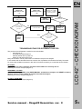
1
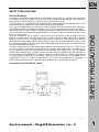
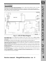
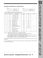
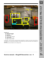
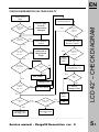
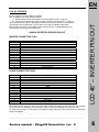
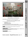
SERVICE MANUAL
Chagall2 DVB-T Generation
SAFETY PRECAUTIONS
1
CHAGALL2 / DVB-T DIGITAL BOARDS
2
LCD 32” VERSION
BLOCK DIAGRAM AND PIN OUT
PSU PIN OUT
BOARD LIST
CHECK DIAGRAM FOR VOLTAGE FAULTY
NO AUDIO FAULTY
ABNORMAL COLOUR
TV FAULTY
LCD 40” VERSION
BLOCK DIAGRAM AND PIN OUT
PSU PIN OUT
BOARD LIST
CHECK DIAGRAM FOR VOLTAGE FAULTY
NO AUDIO FAULTY
ABNORMAL COLOUR
TV FAULTY
LCD 42” VERSION
BLOCK DIAGRAM AND PIN OUT
PSU PIN OUT
INVERTER MODULE PIN OUT
BOARD LIST
CHECK DIAGRAM FOR VOLTAGE FAULTY
NO AUDIO FAULTY
ABNORMAL COLOUR
TV FAULTY
LCD 46” VERSION
INVERTER PIN OUT
FAULTY CHECK
LCD 52”/57” VERSION
BLOCK DIAGRAM AND PIN OUT
PSU PIN OUT
INVERTER MODULE PIN OUT
CHECK DIAGRAM FOR VOLTAGE FAULTY
NO AUDIO FAULTY
ABNORMAL COLOUR
TV FAULTY
LCD 70” VERSION
BOARD LIST
POWER CONNECTION
INVERTER PIN OUT
FAN CONTROL MODULE
CHECK DIAGRAM FOR VOLTAGE FAULTY
DIFFERENT FAULTIES
3
3
3.1
3.2
3.3
3.4
3.5
3.6
4
4
4.2
4.3
4.4
4.5
4.5
4.5
5
5
5
5.1
5.2
5.3
5.4
5.4
5.4
6
6
6.2
7
7
7
7.1
7.2
7.3
7.3
7.3
8
8
8.1
8.2
8.3
8.5
8.7
__________________________________________________________________________________________
Service manual – Chagall2 Generation rev. 0
INDEX
EN
EN
SAFETY PRECAUTIONS
Leakage Current Hot Check circuit
SAFETY PRECAUTIONS
General Guidance
An insulation Transformer should always be used during the servicing of a receiver whose chassis is
not isolated from the AC power line. Use a transformer of adequate power rating as this protects the
technician from accidents resulting in personal injury from electrical shocks.
It will also protect the receiver and it's components from being damaged by accidental shorts of the
circuitry that may be inadvertently introduced during the service operation.
If any fuse (or Fusible Resistor) in this monitor is blown, replace it with the specified. When replacing a
high wattage resistor (Oxide Metal Film Resistor, over 1W), keep the resistor 10mm away from PCB.
Keep wires away from high voltage or high temperature parts. Leakage Current Cold Check (Antenna
Cold Check) with the instrument AC plug removed from AC source, connect an electrical jumper across
the two AC plug prongs.
Place the AC switch in the on position, connect one lead of ohm-meter to the AC plug prongs tied
together and touch other ohm-meter lead in turn to each exposed metallic parts such as antenna
terminals, phone jacks, etc. If the exposed metallic part has a return path to the chassis, the measured
resistance should be between 1M Ohm and 5.2M Ohm. When the exposed metal has no return path to
the chassis the reading must be infinite. Other abnormality exists that must be corrected before the
receiver is returned to the customer.
Leakage Current Hot Check (See below Figure) Plug the AC cord directly into the AC outlet. Do not
use a line Isolation Transformer during this check. Connect 1.5K/10watt resistor in parallel with a
0.15uF capacitor between a known good earth ground (Water Pipe, Conduit, etc.) and the exposed
metallic parts. Measure the AC voltage across the resistor using AC voltmeter with 1000 ohms/volt or
more sensitivity. Reverse plugs the AC cord into the AC outlet and repeats AC voltage measurements
for each exposed metallic part. Any voltage measured must not exceed 0.75 volt RMS that is
corresponds to 0.5mA. In case any measurement is out of the limits specified, there is possibility of
shock hazard and the set must be checked and repaired before it is returned to the customer.
__________________________________________________________________________________________
Service manual – Chagall2 Generation rev. 0
1
EN
A
C
B
CN4
FIG. 1 – CHAGALL2 DIGITAL BOARD AND DVB-T MODULE
A – Main Board Chagall2
B – Sub Board Chagall2
C – DVB-T Module
FIG.1 shows a typical Chagall2 Digital Board (composed by Main and Sub Board) and DVB-T (Digital
Video Broadcasting – Terrestrial) module for digital tuner signal.
In general this configuration is the same for all products (LCD and PDP versions).
In the next all product configurations will be explained. Use them to check and find the main faulty and
then make the request of spare part to Service Center.
Connectors and pin out will be different for every product.
In the next will be described the block diagram, pin out tables for PSU and inverter modules, check
diagram to find voltages faulties, troubleshooting for different other faulty and these informations will
have some difference about the kind of product. So we will see in sequence these models: LCD 32”,
LCD 40”, LCD 42”, LCD 46”, LCD 52”, LCD 57”, LCD 70”, PD 42”, PD 50”.
For some model there are different versions depending on the release of the panel and so some
different to analyze can be present.
The LCD panel versions can have single or double inverter module depending on the release of the
panel.
Digital Board is the same version but schematics will be different because PSU will have a connection
more.
CHAGALL2 DIGITAL BOARD
CHAGALL2 / DVB-T DIGITAL BOARDS
This digital board is created for TV configurations to have analog (terrestrial) and digital tuner (DVB-T).
In the next will be explained how to check and find faulties for Plasma and LCD product.
The analysis is different because Plasma Display and LCD Display are totally different technologies.
Chagall2 Digital Board has different hardware configuration because every panel (Plasma Display,
LCD Display or producer) has different timings or voltages. The specific of each display is defined by
the producer and the firmware to mage the digital board is realized using these specifics.
It is really important to have the product code for every request to Service Center so that the spare part
will be surely in the hardware version needed and with the firmware customized for the product.
To check and find faulty refer to the section of the specific product and when the problem is
found check product code and serial number to make the request of spare part faulty to Service
Center.
__________________________________________________________________________________________
Service manual – Chagall2 Generation rev. 0
2
EN
Fig. 2
MAIN BOARD CHAGALL2 (CN14) to CN200 of PSU
Pin
Signal
Description
1
12VA
12 V Analog
2
12VA
12 V Analog
3
GND-A
Ground Analog
4
12VD
12 V Digital
5
12VD
12 V Digital
6
GND
Ground
7
GND
Ground
8
GND
Ground
9
5VD
5 V Digital
10
5VD
5 V Digital
11
STB-5V
5 V stand by
12
PWR-ON
Power On to PSU (active LOW)
MAIN BOARD CHAGALL2 (CN12) to CN402 of PSU
Pin
Signal
Description
1
Not Used
Not Used
2
Not Used
Not Used
3
DIMM
Dimming Panel
4
BL_ON
Backlight ON
LCD 32” BLOCK DIAGRAM / PIN OUT
LCD 32” VERSION
__________________________________________________________________________________________
Service manual – Chagall2 Generation rev. 0
3
EN
SUB BOARD CHAGALL2 (CN2)
Pin
Signal
1
NC
2
L_OUT +
3
L_OUT 4
NC
5
R_OUT +
6
R_OUT -
Description
Not Connected
Left Out +
Left Out Not connected
Right Out +
Right Out -
Fig. 3
LCD 32” PSU PIN OUT
PSU - PVP2150 PIN OUT
__________________________________________________________________________________________
Service manual – Chagall2 Generation rev. 0
3.1
EN
Pin N.
1
2
3
4
5
6
7
8
9
10
11
12
13
14
PIN CONFIGURATION
24V
24V
24V
24V
24V
GND
GND
GND
GND
GND
No Connection
Backlight ON/OFF ( ON: 2,4V ~ 5,25V ; OFF: - 0,3V ~ 0,8V )
Dimming Control (0V = Min; 3,3V = Max)
No Connection
Referring to FIG.2 for connection between PSU-Panel-Digital Board.
E
FIG. 4
D
A
F
B
LCD 32” BOARD LIST
INVERTER INPUT PIN CONFIGURATION (FROM CN401 OF PSU)
C
BOARD LIST
A) Main Board Chagall2
B) Sub Board Chagall2
C) EMI Filter
D) DVBT Module
E) Power Supply PVP2150
F) Audio Module
__________________________________________________________________________________________
Service manual – Chagall2 Generation rev. 0
3.2
EN
CHECK DIAGRAM FOR VOLTAGE FAULTY
This analysis is for display with no image and to find only problem to have pictures.
Connect Power
Cable
220/110 V in
output EMI
Filter?
Switch On with
Local Keyboard
No
Power Cable
not well
connected Or
damaged
Yes
Check Pin 1
CN200 on
PSU: 0V ?
No
Is Main
Switch ON?
No
Turn On Main
Switch
Switch On with
Remote Control
Yes
Check CN100
on PSU:
220/110 V ?
No
Cable not well
connected or
Main Switch
Faulty
Yes
Local
Keyboard
Faulty
Yes
Check Pin 2
CN200 of
PSU: 5 V ?
Check Pin 1
CN200 on
PSU: 0V ?
No
No
Fuse PSU
ok?
No
Check Cable Local
Keyboard/IR from CN6
Main Board (FIG.4 – A)
Yes
Yes
PSU faulty
Yes
Cable is
OK?
Change Fuse
Check Pin 1
CN200 on
PSU: 0V ?
No
No
Connect /
Change Cable
No PSU output
LCD 32” – NO IMAGE
Yes
Main
Board
Faulty
Yes
Display
(lamps) ON?
No
Yes
Image / OSD
present?
Yes
OK
No
CONTINUE IN
THE NEXT PAGE
CONTINUE IN
THE NEXT PAGE
– “A”
– “B”
__________________________________________________________________________________________
Service manual – Chagall2 Generation rev. 0
3.3
CONTINUE
FROM THE
PREVIOUS PAGE
– “A”
Check Digital
Cable from J5 Main
Board to LVDS
connector panel
CONTINUE
FROM THE
PREVIOUS PAGE
– “B”
Check CN401 (or
CN400) on PSU
Change
LVDS Cable
No
Cable OK?
Yes
Voltages OK
(ref. To inverter
pin out) ?
No
Disconnect cable from
CN400 (or CN401)
Check CN401
(or CN400) on
PSU
Main Board
Faulty or
Panel Faulty
Yes
Yes
Inverter/
panel
Faulty
Voltages OK
(ref. To inverter
pin out) ?
No
PSU faulty
TROUBLESHOOTING FOR DIFFERENT FAULTIES
The previous Check Diagram is useful for the main faulties:
- panel lamps off
- no image with panel lamps on
- stand by status and no power on
- switch on and switch off in loop
Many other faulties can be present but not included in the previous analysis.
In this section will be described the most common list of problems to find where the faulty is located.
For every other faulties not present in the next list it will be necessary to contact the Service Center.
NO AUDIO
NOTE: Before to start in analysis check the audio cable to be sure they are ok.
Connect Audio from
the source to the
monitor (refer to user
manual)
Volume > 0 and
MUTE = OFF
(use Audio
MENU to set)
Select INPUT
matching with audio
source used
Audio is
present ?
Yes
CONTINUE from the
next page “C1”
Audio switch in
INTERNAL position
(refer to user manual)
No
CONTINUE in the
next page “B1”
CONTINUE in the
next page “A1”
LCD 32” – NO IMAGE / AUDIO FAULTY
EN
__________________________________________________________________________________________
Service manual – Chagall2 Generation rev. 0
3.4
EN
CONTINUE from the
previous page “A1”
No
CONTINUE from the
previous page “B1”
Checked Internal
Audio with all
inputs ?
Check audio
setting of the
source
Audio
settings
OK ?
Yes
No
Audio OK
for every
input?
Yes
No
Configure Audio
settings of the
source
Digital Board
faulty (main
or sub)
Yes
Yes
Audio
present?
Yes
OK
No
Connection
Sub Board /
Audio module
ok?
No
No
Cable SUB
Board/Audio
Module Faulty
Audio switch
in EXTERNAL
position (refer
to user manual)
Audio
present?
Yes
Audio Module
Faulty
ABNORMAL COLOUR
NOTE: check image MENU using USER MANUAL and before to analyze, use RESET to factory
defaults function. If the problem is present start with the analysis.
Yes
Source
Settings
OK?
Check Source
settings
Change Source
Settings
Same problem
with Video and
Graphic inputs?
No
Yes
Use
FACTORY
TEST (*)
No
Problem
present
again?
Yes
Same problem
with TV and
Scart?
No
No
Main Board
Faulty
CONTINUE
in the next
page “B2”
Graphic
input
problem?
Yes
No
Main Board
Faulty
LCD 32” – AUDIO FAULTY
CONTINUE in
the previous page
“C1”
Yes
CONTINUE
in the next
page “A2”
Main Board
Faulty
__________________________________________________________________________________________
Service manual – Chagall2 Generation rev. 0
3.5
EN
CONTINUE
from the
previous
page “B2”
Problem in
TV?
No
CONTINUE
from the
previous
page “A2”
Check Digital
Cable
Sub Board
Faulty
Main Board
Faulty
No
Digital
cable OK?
Yes
Digital Cable
Faulty
Display
Faulty
(*) FACTORY TEST
To activate this factory menu it is necessary to use the next procedure:
1) VOLUME to “0”
2) Push in sequence the next 4 keys in less of 5 seconds:
a. Picture
b. Menu
c. Sound
d. Sleep
3) It will appear a menu with HEATRUN function to launch internal test pattern
Using internal test pattern the image is not decoded by a external source and in this case if some
problem is present in output the problem is not of the digital board but it can be digital cable or
LCD/plasma panel.
TV INPUT PROBLEMS
If monitor does not receive any channel, it could be one of the next situations:
- Cable is not connected
- TV settings are not correct for the country standard
- Wall connector or cable connector has not a good ground contact
- Internal wire of the cable antenna is damaged
In one of the previous situations it will not work DTV input too because the signal is the same for TV
tuner and DVB-T tuner.
After the previous checks are made the only possible faulty can be Sub Board.
If no channel is stored during tuning Æ Main Board Faulty
If strong noise is many inputs Æ check antenna installation or some near interference installation is
present.
LCD 32” – COLOUR PROBLEM
Yes
__________________________________________________________________________________________
Service manual – Chagall2 Generation rev. 0
3.6
EN
In the next it will be shown the block diagram for LCD 40” FHD (full high definition) version. The same
schematic can be used for some LCD 46” version with the only difference that in this case the inverter
module will have two connections between inverter module and PSU board, but this will be explained in
the LCD 46” section.
Fig. 5 – LCD 40” Block Diagram
MAIN BOARD CHAGALL2 (CN14) to CN04 of PSU
Pin
Signal
Description
1
12VA
12 V Analog
2
12VA
12 V Analog
3
GND-A
Ground Analog
4
12VD
12 V Digital
5
12VD
12 V Digital
6
GND
Ground
7
GND
Ground
8
GND
Ground
9
5VD
5 V Digital
10
5VD
5 V Digital
11
STB-5V
5 V stand by
12
PWR-ON
Power On to PSU (active LOW)
LCD 40” – BLOCK DIAGRAM / PIN OUT
LCD 40” VERSION
__________________________________________________________________________________________
Service manual – Chagall2 Generation rev. 0
4
MAIN BOARD CHAGALL2 (CN12) to CN03 of PSU
Pin
Signal
Description
1
Not Used
Not Used
2
Not Used
Not Used
3
DIMM
Dimming Panel
4
BL_ON
Backlight ON
SUB BOARD CHAGALL2 (CN2)
Pin
Signal
1
NC
2
L_OUT +
3
L_OUT 4
NC
5
R_OUT +
6
R_OUT -
Description
Not Connected
Left Out +
Left Out Not connected
Right Out +
Right Out -
PSU - PVP2420 / PVP3140
For these products were used two different PSU versions: PVP 2420 and PVP 3140.
Pin out configuration is the same and Lay Out is the same but the components are different.
In the next there are the pictures to check if PSU is PVP 2420 or PVP 3140 version in simple way.
This information can be important to check spare part when you must replace it with a new one but to
request the spare part it is necessary only the product code because for the two versions were created
different product codes.
PVP 2420
PVP 3140
Looking PVP 2420 and PVP 3140 pictures it is possible to see the next differences:
IN RED Æ PVP2420 has not some components that are presents in PVP 3140
IN YELLOW Æ PVP 2420 transformer is smaller than PVP 3140 transformer
IN GREEN Æ there is the indication of the version (see FIG. 6) and sometimes if indication is not
present, it is possible to look label (see FIG. 7).
FIG. 6
LCD 40” – DIGITAL BOARD PIN OUT
EN
FIG. 7
__________________________________________________________________________________________
Service manual – Chagall2 Generation rev. 0
4.1
EN
PSU - PVP2420 / PVP3140 PIN OUT
LCD 40” – PSU PIN OUT
FIG. 8
NOTE: looking PIN OUT indications on PSU board there is a mismatch with the document here
attached (FIG. 8). Refer to the PIN OUT of this service manual.
__________________________________________________________________________________________
Service manual – Chagall2 Generation rev. 0
4.2
EN
BOARD LIST
A) Main Board Chagall2
B) Sub Board Chagall2
C) EMI Filter
D) DVBT Module
E) Power Supply PVP2420 (PVP 3140 for the last version product)
F) Audio Module
Board list is the same of the LCD 32” version (page 3.2 – FIG. 4)
LCD 40” – INVERTER PIN CONFIGURATION
INVERTER INPUT PIN CONFIGURATION (FROM CN05 OF PSU)
__________________________________________________________________________________________
Service manual – Chagall2 Generation rev. 0
4.3
EN
CHECK DIAGRAM FOR VOLTAGE FAULTY
This analysis is for display with no image and to find only problem to have pictures.
Connect Power
Cable
220/110 V in
output EMI
Filter?
Switch On with
Local Keyboard
No
Power Cable
not well
connected Or
damaged
Yes
Check Pin 12
CN04 on
PSU: 0V ?
No
Is Main
Switch ON?
No
Turn On Main
Switch
Switch On with
Remote Control
Yes
Check CN101
on PSU:
220/110 V ?
No
Cable not well
connected or
Main Switch
Faulty
Yes
Local
Keyboard
Faulty
Yes
Check Pin 11
CN04 of PSU:
5V ?
Check Pin 12
CN04 on
PSU: 0V ?
No
No
Fuse PSU
ok?
No
Check Cable Local
Keyboard/IR from CN6
Main Board (FIG.4 – A)
Yes
Yes
PSU faulty
Yes
Cable is
OK?
Change Fuse
Check Pin 12
CN04 on
PSU: 0V ?
No
No
Connect /
Change Cable
No PSU output
LCD 40” – NO IMAGE
Yes
Main
Board
Faulty
Yes
Display
(lamps) ON?
No
Yes
Image / OSD
present?
Yes
OK
No
CONTINUE IN
THE NEXT PAGE
CONTINUE IN
THE NEXT PAGE
– “A”
– “B”
__________________________________________________________________________________________
Service manual – Chagall2 Generation rev. 0
4.4
CONTINUE
FROM THE
PREVIOUS PAGE
– “A”
CONTINUE
FROM THE
PREVIOUS PAGE
– “B”
Check CN05 (or
CN06) on PSU
Check Digital
Cable from J5 Main
Board to LVDS
connector panel
Change
LVDS Cable
No
Cable OK?
Yes
Voltages OK
(ref. To inverter
pin out) ?
No
Disconnect cable from
CN05 (or CN06)
Check CN05
(or CN06) on
PSU
Main Board
Faulty or
Panel Faulty
Yes
Inverter/
panel
Faulty
Yes
Voltages OK
(ref. To inverter
pin out) ?
No
PSU faulty
TROUBLESHOOTING FOR DIFFERENT FAULTIES
The previous Check Diagram is useful for the main faulties:
- panel lamps off
- no image with panel lamps on
- stand by status and no power on
- switch on and switch off in loop
Many other faulties can be present but not included in the previous analysis.
In this section will be described the most common list of problems to find where the faulty is located.
For every other faulties not present in the next list it will be necessary to contact the Service Center.
NO AUDIO
NOTE: Before to start in analysis check the audio cable to be sure they are ok.
Referring to LCD 32” analysis (Page 3.4)
ABNORMAL COLOUR
NOTE: check image MENU using USER MANUAL and before to analyze, use RESET to factory
defaults function. If the problem is present start with the analysis.
Referring to LCD 32” analysis (Page 3.5)
TV INPUT PROBLEMS
Referring to LCD 32” analysis (Page 3.6)
LCD 40” – NO IMAGE / AUDIO FAULTY
EN
__________________________________________________________________________________________
Service manual – Chagall2 Generation rev. 0
4.5
EN
In the next it will be shown the block diagram for LCD 42” FHD (full high definition) version. The same
schematic can be used for some LCD 46” version.
This product has 2 inverter modules and so PSU has 2 connection to supply the 2 half of the panel.
Some LCD 46” version was produced with the same configuration of the next Block Diagram because
the panel release is with 2 inverter modules.
Fig. 9 – LCD 42” Block Diagram
The connections from PSU to Digital Board Chagall2 are the same of Page 4 and 4.1 (Refer to CN14CN12-CN2 pin out).
Digital board is the same of the other LCD version but with different firmware release (created for LCD
42” version).
PSU used for this monitor is PVP3140 (page 4.1) and so for the pin out refer to Page 4.2.
For this product are used the two connections CN05 and CN06 output connectors from PSU because
display has two inverter modules. These two modules are necessary to manage each of the two half of
panel lamps (see FIG. 9 in the top).
CN05 and CN06 have the same pin out but cables are differents. In fact the 2 inverter modules have
different priority (master and slave) and different connectors (14 pins the Master connector and 12 pins
the Slave connector).
In every case it is possible to swap CN05 and CN06 to check if PSU output are working correctly if laps
are not turning on.
To switch on the panel it is necessary to send Backlight command and Dimmer command using one
inverter module (Master).
In the next page there is the INVERTER CONNECTOR PIN CONFIGURATION that can be necessary
to make check for some turn on problem.
LCD 42” – BLOCK DIAGRAM / PIN OUT
LCD 42” VERSION
__________________________________________________________________________________________
Service manual – Chagall2 Generation rev. 0
5
INVERTER CONNECTOR PIN CONFIGURATION
For the Master connector (14 pins) are used Pin 12 and Pin 13 while Pin 11 and Pin 14 are not
connected.
In the next page there is a picture of LCD 42” version and it is possible to see the inverter modules
connections with PSU board.
__________________________________________________________________________________________
Service manual – Chagall2 Generation rev. 0
LCD 42” – INVERTER MODULES PIN OUT
EN
5.1
Fig. 10
E
D
A
G
F
B
C
H
BOARD LIST
A) Main Board Chagall2
B) Sub Board Chagall2
C) EMI Filter
D) DVBT Module
E) Power Supply PVP3140
F) Audio Module
G) Master inverter module
H) Slave inverter module
Looking FIG. 10 (on the top) it is clear that board configuration is similar to the other versions with the
only difference of the panel that has Master inverter Module (on the left) and Slave inverter Module (on
the right).
Now use the next Check Block to find voltage faulty.
LCD 42” – INVERTER MODULES PIN OUT
EN
__________________________________________________________________________________________
Service manual – Chagall2 Generation rev. 0
5.2
EN
CHECK DIAGRAM FOR VOLTAGE FAULTY
Connect Power
Cable
No
Power Cable
not well
connected Or
damaged
Yes
Check Pin 12
CN04 on
PSU: 0V ?
Yes
No
Is Main
Switch ON?
No
Turn On Main
Switch
Switch On with
Remote Control
Yes
Check CN101
on PSU:
220/110 V ?
No
Cable not well
connected or
Main Switch
Faulty
Yes
Local
Keyboard
Faulty
Yes
Check Pin 11
CN04 of PSU:
5V ?
No
No
Fuse PSU
ok?
Yes
PSU faulty
Yes
Change Fuse
No
No
Check Cable Local
Keyboard/IR from CN6
Main Board (FIG.4 – A)
Yes
Check Pin 12
CN04 on
PSU: 0V ?
Check Pin 12
CN04 on
PSU: 0V ?
Cable is
OK?
No
Connect /
Change Cable
No PSU output
Main
Board
Faulty
Yes
All display
ON?
No
CONTINUE IN
THE NEXT PAGE
Yes
Image / OSD
present?
Yes
OK
LCD 42” – CHECK DIAGRAM
220/110 V in
output EMI
Filter?
Switch On with
Local Keyboard
No
CONTINUE IN
THE NEXT PAGE
– “B”
– “A”
__________________________________________________________________________________________
Service manual – Chagall2 Generation rev. 0
5.3
EN
CONTINUE
FROM THE
PREVIOUS PAGE
– “B”
Check CN05 and
CN06 on PSU
Check Digital
Cable from J5 Main
Board to LVDS
connector panel
Change
LVDS Cable
No
Cable OK?
Yes
Voltages OK
(ref. To inverter
pin out) ?
No
Disconnect cable from
CN05 and CN06
Check CN05
and CN06 on
PSU
Main Board
Faulty or
Panel Faulty
Yes
Inverter/
panel
Faulty
Yes
Voltages OK
(ref. To inverter
pin out) ?
No
PSU faulty
TROUBLESHOOTING FOR DIFFERENT FAULTIES
The previous Check Diagram is useful for the main faulties:
- panel lamps off
- no image with panel lamps on
- stand by status and no power on
- switch on and switch off in loop
Many other faulties can be present but not included in the previous analysis.
In this section will be described the most common list of problems to find where the faulty is located.
For every other faulties not present in the next list it will be necessary to contact the Service Center.
NO AUDIO
NOTE: Before to start in analysis check the audio cable to be sure they are ok.
Referring to LCD 32” analysis (Page 3.4)
ABNORMAL COLOUR
NOTE: check image MENU using USER MANUAL and before to analyze, use RESET to factory
defaults function. If the problem is present start with the analysis.
Referring to LCD 32” analysis (Page 3.5)
TV INPUT PROBLEMS
Referring to LCD 32” analysis (Page 3.6)
LCD 42” – CHECK DIAGRAM
CONTINUE
FROM THE
PREVIOUS PAGE
– “A”
__________________________________________________________________________________________
Service manual – Chagall2 Generation rev. 0
5.4
EN
For this product exists two different versions.
The LCD display can have different release :
1) single inverter module with double connectors (refer to FIG.5 – page 4)
2) two inverter modules with single connector each one (refer to FIG. 9 – page 5)
All the boards are the same in the product versions and the only difference is the display.
The analysis can use the same concept used for the previous product described.
About the pin out tables it is possible to refer to page 4 and 4.1 (Digital Board pin out).
PSU board is PVP3140 (refer to page 4.2)
SINGLE INVERTER VERSION PIN OUT
MASTER CONNECTOR (CN1)
Pin N.
1
2
3
4
5
6
7
8
9
10
11
12
13
14
PIN CONFIGURATION
24V
24V
24V
24V
24V
GND
GND
GND
GND
GND
No Connection
Backlight ON/OFF ( ON: 2,4V ~ 5,25V ; OFF: - 0,3V ~ 0,8V )
Dimming Control (0V = Min; 3,3V = Max)
No Connection
SLAVE CONNECTOR (CN2)
Pin N.
1
2
3
4
5
6
7
8
9
10
11
12
13
14
PIN CONFIGURATION
24V
24V
24V
24V
24V
GND
GND
GND
GND
GND
Reserved
Reserved
Reserved
Reserved
LCD 46” – INVERTER PIN OUT
LCD 46” VERSION
The cables are the same and pin out of PSU board (CN05 and CN06) are the same too, but to switch
on the monitor it is necessary to have output 12 and 13 of CN1 (see Master Connector pin out).
To check some inverter or PSU faulty it is possible to swap CN05 and CN06 connectors and verify with
tester the voltages.
__________________________________________________________________________________________
Service manual – Chagall2 Generation rev. 0
6
EN
DOUBLE INVERTER VERSION PIN OUT
Pin N.
1
2
3
4
5
6
7
8
9
10
11
12
13
14
PIN CONFIGURATION
24V
24V
24V
24V
24V
GND
GND
GND
GND
GND
No Connection
Backlight ON/OFF ( ON: 2,4V ~ 5, 5V ; OFF: 0V ~ 0,8V )
Dimming Control (0V = Min; 3,3V = Max)
No Connection
SLAVE CONNECTOR (right inverter module)
Pin N.
1
2
3
4
5
6
7
8
9
10
11
12
13
14
PIN CONFIGURATION
24V
24V
24V
24V
24V
GND
GND
GND
GND
GND
Reserved
Reserved
Reserved
Reserved
As the previous panel version the connection uses same cables but only one inverter module needs
switch on command using pin 12 and pin 13 voltages (refer to Master connector – left inverter module).
The analysis can be made swapping the cables to find some faulty on PSU or panel because PSU
output CN05 and CN06 are totally the same.
Fig. 10 Page 5.2 shows a double inverter configuration for 42” version product very similar to 46”
version with two inverter module.
In the next page it is visible a typical single inverter configuration 46” product (FIG. 11). On the right
there is a metal cover but no inverter module is present inside.
For the check it must be checked only the connectors visible on the left of the picture.
LCD 46” – INVERTER PIN OUT
MASTER CONNECTOR (left inverter module)
__________________________________________________________________________________________
Service manual – Chagall2 Generation rev. 0
6.1
EN
Single inverter with double connector
Metal cover without inverter module
CHECK DIAGRAM FOR VOLTAGE FAULTY
Refer to page 5.3 / 5.4. The analysis is the same of LCD 42” product version and it is not important if
there are 2 inverter modules or only one. In every case the 2 panel version
TROUBLESHOOTING FOR DIFFERENT FAULTIES
The previous Check Diagram is useful for the main faulties:
- panel lamps off
- no image with panel lamps on
- stand by status and no power on
- switch on and switch off in loop
Many other faulties can be present but not included in the previous analysis.
In this section will be described the most common list of problems to find where the faulty is located.
For every other faulties not present in the next list it will be necessary to contact the Service Center.
NO AUDIO
NOTE: Before to start in analysis check the audio cable to be sure they are ok.
Referring to LCD 32” analysis (Page 3.4)
LCD 46” – FAULTY CHECK
FIG.11
ABNORMAL COLOUR
NOTE: check image MENU using USER MANUAL and before to analyze, use RESET to factory
defaults function. If the problem is present start with the analysis.
Referring to LCD 32” analysis (Page 3.5)
TV INPUT PROBLEMS
Referring to LCD 32” analysis (Page 3.6)
__________________________________________________________________________________________
Service manual – Chagall2 Generation rev. 0
6.2
EN
LCD 52”/ 57” VERSION
Pin out from Chagall2 Digital Board to Master PSU is totally the same of the Page 4 and 4.1 (Refer to
CN14-CN12-CN2 pin out).
MAIN BOARD CHAGALL2 (CN14) to CN04 of PSU MASTER
Pin
Signal
Description
1
12VA
12 V Analog
2
12VA
12 V Analog
3
GND-A
Ground Analog
4
12VD
12 V Digital
5
12VD
12 V Digital
6
GND
Ground
7
GND
Ground
8
GND
Ground
9
5VD
5 V Digital
10
5VD
5 V Digital
11
STB-5V
5 V stand by
12
PWR-ON
Power On to PSU (active LOW)
LCD 52”/57” – BLOCK DIAGRAM
This product needs two power supply units to manage the double inverter display.
PSUs are PVP3140 version but they are differents.
Main PSU supplies the digital board Chagall2 and secondary PSU is a modified version of PVP3140
with a load resistor on the rear.
__________________________________________________________________________________________
Service manual – Chagall2 Generation rev. 0
7
CN04 of MASTER PSU to CN04 of SLAVE PSU
Pin
Signal
1
N.C.
2
N.C.
3
N.C.
4
N.C.
5
N.C.
6
N.C.
7
N.C.
8
N.C.
9
N.C.
10
N.C.
11
N.C.
12
PWR-ON
Description
Not connected
Not connected
Not connected
Not connected
Not connected
Not connected
Not connected
Not connected
Not connected
Not connected
Not connected
Power On to PSU (active LOW)
The SLAVE PSU is necessary to send voltages to the second inverter module and it receives only
Power ON command from digital board. To work correctly SLAVE PSU needs to be modified with a
rear loads. A label is present on every PSU with the code, so that it is possible to check if spare part is
Master or Slave. In the case that only one PSU is faulty it can be requested the spare part reading the
code on the label or, in other case, it is possible to request PSU board specifying if it is master
(connection with Digital Board) or slave (only Pin 12 – CN04 connection) and the product code of the
TV.
INVERTER INPUT PIN CONFIGURATION (FROM CN05 OF MASTER / SLAVE PSU)
Cables used for the two inverter modules are the same but only Master inverter module needs
Backlight and Dimmer commands.
Remembering that CN05 and CN06 on Master and Slave PSUs have the same pin out it is possible to
swap connections between CN05 and CN06 to check if PSU output are faulty, if panel does not switch
on.
In every case use the next Check Diagram to find some possible faulty about no image present.
LCD 52”/57” – INVERTER PIN OUT
EN
__________________________________________________________________________________________
Service manual – Chagall2 Generation rev. 0
7.1
EN
Connect Power
Cable
220/110 V in
output EMI
Filter?
Switch On with
Local Keyboard
No
Power Cable
not well
connected Or
damaged
Yes
Check Pin 12
CN04 on
PSU: 0V ?
Yes
No
Is Main
Switch ON?
No
Turn On Main
Switch
Switch On with
Remote Control
Yes
Check CN101 PSU 1 and 2:
220/110 V ?
No
Cable not well
connected or
Main Switch
Faulty
Yes
Local
Keyboard
Faulty
Yes
Check Pin 11
CN04 of
PSU1: 5 V ?
No
No
Fuse PSU1
ok?
Yes
PSU faulty
Yes
Change Fuse
No
No
Check Cable Local
Keyboard/IR from CN6
Main Board (FIG.4 – A)
Yes
Check Pin 12
CN04 on
PSU1: 0V ?
Check Pin 12
CN04 on
PSU: 0V ?
Cable is
OK?
No
Connect /
Change Cable
No PSU output
Main
Board
Faulty
Yes
Display
(lamps) ON?
No
Yes
Image / OSD
present?
No
CONTINUE IN
THE NEXT PAGE
CONTINUE IN
THE NEXT PAGE
– “A”
– “B”
Yes
OK
NOTE:
PSU 1 = MASTER PSU
PSU 2 = SLAVE PSU
LCD 52”/57” – CHECK DIAGRAM
CHECK DIAGRAM FOR VOLTAGE FAULTY
__________________________________________________________________________________________
Service manual – Chagall2 Generation rev. 0
7.2
EN
CONTINUE
FROM THE
PREVIOUS PAGE
– “B”
Check CN05 (or
CN06) on PSU 1
Check Digital
Cable from J5 Main
Board to LVDS
connector panel
Change
LVDS Cable
No
Cable OK?
Yes
Voltages
OK ?
No
Disconnect cable from
CN05 (or CN06) of
PSU 1
Check CN05
and CN06 on
PSU 1
Main Board
Faulty or
Panel Faulty
Yes
Check CN05 (or
CN06) on PSU 2
Inverter/
panel
Faulty
Yes
Voltages
OK ?
No
Voltages
OK ?
Yes
PSU 1 faulty
PSU 2 faulty
No
Disconnect cable from
CN05 (or CN06) of
PSU 2
Check CN05 and
CN06 on PSU 2
Yes
Voltages
OK ?
No
TROUBLESHOOTING FOR DIFFERENT FAULTIES
The previous Check Diagram is useful for the main faulties:
- panel lamps off
- no image with panel lamps on
- stand by status and no power on
- switch on and switch off in loop
Many other faulties can be present but not included in the previous analysis.
In this section will be described the most common list of problems to find where the faulty is located.
For every other faulties not present in the next list it will be necessary to contact the Service Center.
NO AUDIO
NOTE: Before to start in analysis check the audio cable to be sure they are ok.
Referring to LCD 32” analysis (Page 3.4)
ABNORMAL COLOUR
NOTE: check image MENU using USER MANUAL and before to analyze, use RESET to factory
defaults function. If the problem is present start with the analysis.
Referring to LCD 32” analysis (Page 3.5)
LCD 52”/57” – CHECK DIAGRAM
CONTINUE
FROM THE
PREVIOUS PAGE
– “A”
TV INPUT PROBLEMS
Referring to LCD 32” analysis (Page 3.6)
__________________________________________________________________________________________
Service manual – Chagall2 Generation rev. 0
7.3
EN
LCD 70” VERSION
In the FIG. 12 is visible LCD 70” monitor version in the back to describe easily the configuration of this
product.
B
C
A
F
G
D
H
N
L
K
M
I
J
FIG. 12
BOARDS LIST (REFER TO FIG. 12)
SIGNAL BOARDS
A) Main Board Chagall2
B) Sub Board Chagall2
C) Speaker Module
D) DVB-T Module
POWER BOARDS
E) Power Distribution Module
F) EMI Filter
G) Power Supply Module (PSU) 1 (slave)
H) Power Supply Module (PSU) 2 (master)
I) Power Supply Module (PSU) 3 (slave)
J) Power Supply Module (PSU) 4 (slave)
FANS
K)
L)
M)
N)
LD 70” – BOARD LIST
E
FAN 1
FAN 2
FAN 3
Fan Control Module
__________________________________________________________________________________________
Service manual – Chagall2 Generation rev. 0
8
EN
POWER CONNECTION
Power
Distribution
Module (PDM)
PSU 1
FIG 13
To Digital
Board
PSU 2
PSU 4
Main Switch
PSU 3
Master
inverter module
In FIG. 13 is visible the connection starting from Main Plug Connector and arriving to Inverter Modules
of the panel.
PSU1, PSU3, PSU4 are totally the same version. PSU2 has a different hardware configuration (Refer
to spare part list for the code).
PSUs are PVP3140 version and PSU2 is the Master while the others three are Slaves.
Every PSU gives output voltages only if ON Command is present from Digital Board (“A” board in FIG.
12). PSU2 is directly connected with the digital board and from CN04 connector there is a cascade
connection to send POWER ON wire connection to the others PSU.
In the there are PIN out tables from Digital Board to PSU2 and from PSU2 to the others PSU.
MAIN BOARD CHAGALL2 (CN14) to CN04 of PSU 2 (MASTER)
Pin
Signal
Description
1
12VA
12 V Analog
2
12VA
12 V Analog
3
GND-A
Ground Analog
4
12VD
12 V Digital
5
12VD
12 V Digital
6
GND
Ground
7
GND
Ground
8
GND
Ground
9
5VD
5 V Digital
10
5VD
5 V Digital
11
STB-5V
5 V stand by
12
PWR-ON
Power On to PSU (active LOW)
LD 70” – POWER CONNECTION
EMI Filter
__________________________________________________________________________________________
Service manual – Chagall2 Generation rev. 0
8.1
CN04 of PSU 1 (MASTER) to CN04 of SLAVE PSUs (PSU 1, PSU 3, PSU 4)
Pin
Signal
Description
1
N.C.
Not connected
2
N.C.
Not connected
3
N.C.
Not connected
4
N.C.
Not connected
5
N.C.
Not connected
6
N.C.
Not connected
7
N.C.
Not connected
8
N.C.
Not connected
9
N.C.
Not connected
10
N.C.
Not connected
11
N.C.
Not connected
12
PWR-ON
Power On to PSU (active LOW)
Pin out from Chagall2 Digital Board to Master PSU is totally the same of the Page 4 and 4.1 (Refer to
CN14-CN12-CN2 pin out).
The BL_ON and DIMMER command to switch on the display are supplied by the Master PSU (PSU2)
that is connected to the second inverter module in the bottom from right (see FIG. 13). Other
connections are not possible to turn on the display.
In the next there is the pin out of the inverter module
MASTER INVERTER PIN CONFIGURATION (see FIG.13)
Pin N.
1
2
3
4
5
6
7
8
9
10
11
12
13
14
PIN CONFIGURATION
24V
24V
24V
24V
24V
GND
GND
GND
GND
GND
No Connection
Backlight ON/OFF ( ON: 2,4V ~ 5, 5V ; OFF: 0V ~ 0,8V )
Dimming Control (0V = Min; 3,3V = Max)
No Connection
SLAVE INVERTER PIN CONFIGURATION
Pin N.
1
2
3
4
5
6
7
8
9
10
11
12
13
14
PIN CONFIGURATION
24V
24V
24V
24V
24V
GND
GND
GND
GND
GND
Reserved
Reserved
Reserved
Reserved
LCD 70” – INVERTER PIN OUT
EN
__________________________________________________________________________________________
Service manual – Chagall2 Generation rev. 0
8.2
EN
This product needs to have a cooling system necessary to protect display by over burn.
The high consumption of this panel requests an automatic adjustment of the fans, so that the cooling
will be proportional to the instant temperature of the display.
The consumption can strongly change depending on the images used or the input.
To manage in automatic way the cooling of the panel it is present a NTC sensor that checks the
temperature near the control board of the panel (FIG. 14).
This sensor is connected on the Fan Control Module (see FIG. 12 – N) and depending on the
temperature it gives a changing command to have faster or slower speed of the fan.
The voltages for fans it will increase or decrease with higher or lower temperature.
FIG. 14
In the next there is the schematic of the connection to check abnormal situation of the cooling system.
CN 2
CN 8
CN 10
CN 11
CN 12
From CN05 – PSU 3 (slave)
To FAN 1
(K in FIG. 12)
To FAN 2
(L in FIG. 12)
To FAN 3
(M in FIG. 12)
LCD 70” – FAN CONTROL MODULE
FAN CONTROL MODULE
__________________________________________________________________________________________
Service manual – Chagall2 Generation rev. 0
8.3
EN
Pin N. (CN05)
1
2
3
4
5
6
7
8
9
10
11
12
13
14
PIN CONFIGURATION
24 V
24 V
N.C.
N.C.
N.C.
GND
GND
N.C.
N.C.
N.C.
N.C.
N.C.
N.C.
N.C.
Pin N. (CN 2)
1
2
3
4
5
-
PIN OUT CN 2 – FAN CONTROL MODULE
Pin N.
1
2
3
4
5
6
7
8
9
10
11
12
PIN CONFIGURATION
N.C.
NTC (+)
N.C.
N.C.
N.C.
N.C.
N.C.
N.C.
N.C.
N.C.
N.C.
NTC (–)
Fan control module is supplied with 24V and voltage output for FAN has a range starting to about 4V
(25°C) up to 10V.
In the next page there is the check diagram to analyze voltage faulty but for some faulty about cooling
of the monitor refer to the previous section (FAN CONTROL MODULE – 8.3)
LCD 70” – FAN CONTROL MODULE
From CN05 – PSU 3 (SLAVE) to CN 8 – Fan Control Module
__________________________________________________________________________________________
Service manual – Chagall2 Generation rev. 0
8.4
EN
CHECK DIAGRAM FOR VOLTAGE FAULTY
This analysis is for display with no image and to find only problem to have pictures.
Connect Power
Cable
No
220/110 V in
output EMI
Filter?
No
PUS_2 CN4P12 = 0V ?
Power Cable
not well
connected Or
Faulty
No PSU _2
output
Yes
Switch on with
local keyboard
Is Main
Switch ON?
(LED ON)
No
EMI Filter
Faulty
Yes
PUS_2 CN4P12 = 0V ?
Yes
No
220/110 V in
input PDM ?
Cable not well
connected Or
Faulty
No
Switch on with
Remote
Control
Yes
No
220/110 V in
output PDM ?
Cable not well
connected Or
PDM Faulty
Local
Keyboard
Faulty
Yes
PUS_2 CN4P12 = 0V ?
Yes
PSU Fuses
OK ?
No
No
Fuse
Faulty
No
PSU_2
Faulty
Check Cable Local
Keyboard/IR from
CN6 Main Board
(FIG.4 – A )
Yes
PUS_2 CN4P11 = 5V ?
Main Board
Faulty
Yes
No
Yes
All display
ON?
Yes
Cable is
OK?
Connect /
Change
Cable
Image / OSD
present?
Yes
LCD 70” – CHECK DIAGRAM
Yes
OK
CONTINUE
CONTINUE
IN THE NEXT
No
IN THE NEXT
PAGE – “B”
No
PAGE – “A”
__________________________________________________________________________________________
Service manual – Chagall2 Generation rev. 0
8.5
EN
CONTINUE
FROM THE
PREVIOUS PAGE
– “B”
Check CN05 (or
CN06) on PSU 2
Check Digital
Cable from J5 Main
Board to LVDS
connector panel
Change
LVDS Cable
No
Cable OK?
Yes
Voltages
OK?
No
Disconnect cable from
CN05 (or CN06) of
PSU 2
Check CN05
and CN06 on
PSU 2
Main Board
Faulty or
Panel Faulty
Yes
Check CN05 (or
CN06) on PSU_1-3-4
Inverter/
panel
Faulty
Yes
Voltages
OK ?
No
Voltages
OK?
Yes
PSU_2 faulty
PSU_1 / 3 / 4
faulty
No
Disconnect cable from
CN05 (or CN06) of
PSU 1-3-4
Check CN05 and
CN06 on Psu_1-3-4
Yes
Voltages
OK ?
No
It could be present some a trouble only for one inverter module. In this case it is necessary to contact
Service Center and make request about the possibility to solve the problem.
TROUBLESHOOTING FOR DIFFERENT FAULTIES
The previous Check Diagram is useful for the main faulties:
- panel lamps off
- no image with panel lamps on
- stand by status and no power on
- switch on and switch off in loop
Many other faulties can be present but not included in the previous analysis.
In this section will be described the most common list of problems to find where the faulty is located.
For every other faulties not present in the next list it will be necessary to contact the Service Center.
LCD 70” – CHECK DIAGRAM
CONTINUE
FROM THE
PREVIOUS PAGE
– “A”
NO AUDIO
NOTE: Before to start in analysis check the audio cable to be sure they are ok.
Referring to LCD 32” analysis (Page 3.4)
__________________________________________________________________________________________
Service manual – Chagall2 Generation rev. 0
8.6
EN
TV INPUT PROBLEMS
Referring to LCD 32” analysis (Page 3.6)
LCD 70” – DIFFERENT FAULTIES
ABNORMAL COLOUR
NOTE: check image MENU using USER MANUAL and before to analyze, use RESET to factory
defaults function. If the problem is present start with the analysis.
Referring to LCD 32” analysis (Page 3.5)
__________________________________________________________________________________________
Service manual – Chagall2 Generation rev. 0
8.7