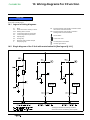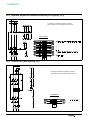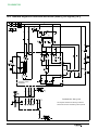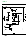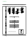
1
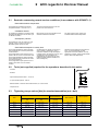
Secondary Distribution Switchgear FLUSARC 36 SF6 Gas-insulated switchboards Instructions Installation - Commissioning FLUSARC 36 SDIOPM0130600- 02 revision: 01 Contents 1 Schneider Electric at your service . . . . . . . . . . . . . . . . . . . . 1 1.1 1.2 1.3 1.4 1.5 Particular instructions for operations and interventions . . . . . . . . . . . . . . . . . . Protection equipments . . . . . . . . . . . . . . . . . . . . . . . . . . . . . . . . . . . . . . . . . . . . . Symbols of information . . . . . . . . . . . . . . . . . . . . . . . . . . . . . . . . . . . . . . . . . . . . . Symbols and important safety informations . . . . . . . . . . . . . . . . . . . . . . . . . . . . Contacts . . . . . . . . . . . . . . . . . . . . . . . . . . . . . . . . . . . . . . . . . . . . . . . . . . . . . . . . . 1 1 1 1 1 2 With regards to this User Manual . . . . . . . . . . . . . . . . . . . . 2 2.1 2.2 2.3 Reminder concerning normal service conditions (in accordance with IEC62271- 1) . . . . . . . . . . . . . . . . . . . . . . . . . . . . . . . . . . . . . . . . . . . . . . . . . . . . . * Permissible ambient temperature . . . . . . . . . . . . . . . . . . . . . . . . . . . . . . . . . . . * Installation altitude . . . . . . . . . . . . . . . . . . . . . . . . . . . . . . . . . . . . . . . . . . . . . . . * Atmospheric pollution . . . . . . . . . . . . . . . . . . . . . . . . . . . . . . . . . . . . . . . . . . . . * Permissible atmospheric humidity level . . . . . . . . . . . . . . . . . . . . . . . . . . . . . . Tools (not supplied) required for the operations described in this notice . . . Tightening torque values [Nm] for standard assemblies (nut + bolt) . . . . . . 2 2 2 2 2 2 2 3 Presentation of the Flusarc 36 . . . . . . . . . . . . . . . . . . . . . . . 3 3.1 3.2 3.3 Identification of the switchboard . . . . . . . . . . . . . . . . . . . . . . . . . . . . . . . . . . . . . Presentation of the Flusarc 36 . . . . . . . . . . . . . . . . . . . . . . . . . . . . . . . . . . . . . . . Legend of mimic diagrams for manual controls . . . . . . . . . . . . . . . . . . . . . . . . 3 3 4 4 Storage - Packing . . . . . . . . . . . . . . . . . . . . . . . . . . . . . . . . . . 5 4.1 4.2 4.3 4.4 4.5 Transport . . . . . . . . . . . . . . . . . . . . . . . . . . . . . . . . . . . . . . . . . . . . . . . . . . . . . . . . Flusarc 36 Unit packing . . . . . . . . . . . . . . . . . . . . . . . . . . . . . . . . . . . . . . . . . . . . Handling . . . . . . . . . . . . . . . . . . . . . . . . . . . . . . . . . . . . . . . . . . . . . . . . . . . . . . . . . Specific transportation requirements . . . . . . . . . . . . . . . . . . . . . . . . . . . . . . . . . Temporary storage – less than 6 months . . . . . . . . . . . . . . . . . . . . . . . . . . . . . . 5 5 5 6 6 5 Handling and Unpacking . . . . . . . . . . . . . . . . . . . . . . . . . . . . 7 5.1 5.2 5.3 Reminder . . . . . . . . . . . . . . . . . . . . . . . . . . . . . . . . . . . . . . . . . . . . . . . . . . . . . . . . Unpacking and handling . . . . . . . . . . . . . . . . . . . . . . . . . . . . . . . . . . . . . . . . . . . Valorizing packaging waste . . . . . . . . . . . . . . . . . . . . . . . . . . . . . . . . . . . . . . . . . Acceptance . . . . . . . . . . . . . . . . . . . . . . . . . . . . . . . . . . . . . . . . . . . . . . . . . . . . . . 7 7 7 7 6 Requirements for internal arc . . . . . . . . . . . . . . . . . . . . . . . . 8 6.1 6.2 Cable cunicle volume > 10 m3 . . . . . . . . . . . . . . . . . . . . . . . . . . . . . . . . . . . . . . Cable cunicle volume < 10 m3 . . . . . . . . . . . . . . . . . . . . . . . . . . . . . . . . . . . . . . 8 8 7 Fixing to the floor for Flusarc 36 switchgear . . . . . . . . . . 9 7.1 Fixing to the floor . . . . . . . . . . . . . . . . . . . . . . . . . . . . . . . . . . . . . . . . . . . . . . . . . . 9 8 Modular Unit installation . . . . . . . . . . . . . . . . . . . . . . . . . . . . 10 8.1 8.2 8.3 Installation procedure . . . . . . . . . . . . . . . . . . . . . . . . . . . . . . . . . . . . . . . . . . . . . . Ground bar connection . . . . . . . . . . . . . . . . . . . . . . . . . . . . . . . . . . . . . . . . . . . . Assembly of the busbar . . . . . . . . . . . . . . . . . . . . . . . . . . . . . . . . . . . . . . . . . . . . Supplies required for the assembly of the busbar . . . . . . . . . . . . . . . . . . . . . . Switchboard status . . . . . . . . . . . . . . . . . . . . . . . . . . . . . . . . . . . . . . . . . . . . . . . . Busbar assembly . . . . . . . . . . . . . . . . . . . . . . . . . . . . . . . . . . . . . . . . . . . . . . . . . . Installation Busbar System protection . . . . . . . . . . . . . . . . . . . . . . . . . . . . . . . . . 10 11 11 11 11 12 15 9 Earthing the Flusarc 36 Unit . . . . . . . . . . . . . . . . . . . . . . . . . 16 9.1 9.2 Location of the connector terminal . . . . . . . . . . . . . . . . . . . . . . . . . . . . . . . . . . . Connecting the earthing cable . . . . . . . . . . . . . . . . . . . . . . . . . . . . . . . . . . . . . . 16 16 10 Connection of the HV cables . . . . . . . . . . . . . . . . . . . . . . . . 17 10.1 10.2 10.3 10.4 10.5 10.6 Opening the cable compartment . . . . . . . . . . . . . . . . . . . . . . . . . . . . . . . . . . . . . Bushings [according to standard EN 50181] . . . . . . . . . . . . . . . . . . . . . . . . . . General connection precautions . . . . . . . . . . . . . . . . . . . . . . . . . . . . . . . . . . . . . Type C connection . . . . . . . . . . . . . . . . . . . . . . . . . . . . . . . . . . . . . . . . . . . . . . . . Passage of the cables . . . . . . . . . . . . . . . . . . . . . . . . . . . . . . . . . . . . . . . . . . . . . . Connection of the cables . . . . . . . . . . . . . . . . . . . . . . . . . . . . . . . . . . . . . . . . . . . 17 17 17 18 18 19 11 Metering panels installation . . . . . . . . . . . . . . . . . . . . . . . . . 21 11.1 11.2 11.3 11.4 11.5 Metering Units . . . . . . . . . . . . . . . . . . . . . . . . . . . . . . . . . . . . . . . . . . . . . . . . . . . . Handling and Unpacking . . . . . . . . . . . . . . . . . . . . . . . . . . . . . . . . . . . . . . . . . . . Fixing to the floor . . . . . . . . . . . . . . . . . . . . . . . . . . . . . . . . . . . . . . . . . . . . . . . . . . Ground bar connection . . . . . . . . . . . . . . . . . . . . . . . . . . . . . . . . . . . . . . . . . . . . Connecting plugs on busbar . . . . . . . . . . . . . . . . . . . . . . . . . . . . . . . . . . . . . . . . 21 21 21 21 22 i FLUSARC 36 11.6 Attaching the cables and connecting the earthing braids . . . . . . . . . . . . . . . . 22 12 Fitting the HV fuses . . . . . . . . . . . . . . . . . . . . . . . . . . . . . . . . . 23 12.1 Dimensions (mm) of the fuses – in accordance with standards IEC60282- 1 and IEC62271- 105 . . . . . . . . . . . . . . . . . . . . . . . . . . . . . . . . . . . . . . . . . . . . . . . . . . . 23 Selection table for fuses . . . . . . . . . . . . . . . . . . . . . . . . . . . . . . . . . . . . . . . . . . . . 23 Fitting a fuse [earthing switch closed] . . . . . . . . . . . . . . . . . . . . . . . . . . . . . . . . 23 Processing fuse packaging . . . . . . . . . . . . . . . . . . . . . . . . . . . . . . . . . . . . . . . . . 25 12.2 12.3 13 Commissioning . . . . . . . . . . . . . . . . . . . . . . . . . . . . . . . . . . . . . 13.1 13.2 13.7 Reminder . . . . . . . . . . . . . . . . . . . . . . . . . . . . . . . . . . . . . . . . . . . . . . . . . . . . . . . . 26 Carry out an inventory of all tools and accessories on completion of the work . . . . 26 Pre- commissioning information . . . . . . . . . . . . . . . . . . . . . . . . . . . . . . . . . . . . . 26 Principle pre- commissioning checks . . . . . . . . . . . . . . . . . . . . . . . . . . . . . . . . 26 Energizing the Flusarc 36 switchgears . . . . . . . . . . . . . . . . . . . . . . . . . . . . . . . . 26 VPIS (Voltage Present Indicating System) . . . . . . . . . . . . . . . . . . . . . . . . . . . . . 26 Voltage Present Indications verifications with a standard unit . . . . . . . . . . . . . 27 Energizing the switchboard . . . . . . . . . . . . . . . . . . . . . . . . . . . . . . . . . . . . . . . . . 27 14 Wiring diagrams for C Function . . . . . . . . . . . . . . . . . . . . . . 28 14.1 14.2 14.3 14.4 14.5 14.6 14.7 14.8 14.9 Legend of wiring diagrams . . . . . . . . . . . . . . . . . . . . . . . . . . . . . . . . . . . . . . . . . Single diagram of the C Unit with motorization kit [See legend § 14.1] . . . . . Standard diagram for manual mechanism [See legend § 14.1] . . . . . . . . . . . Terminal (X1) [See legend § 14.1] . . . . . . . . . . . . . . . . . . . . . . . . . . . . . . . . . . . . Standard diagram for motorised mechanism (24VDC) [See legend § 14.1] . Standard diagram for motorised mechanism (48VDC) [See legend § 14.1] . Standard diagram for motorised mechanism (110VDC) [See legend § 14.1] Standard diagram for motorised mechanism (230VAC) [See legend § 14.1] Terminal box . . . . . . . . . . . . . . . . . . . . . . . . . . . . . . . . . . . . . . . . . . . . . . . . . . . . . . 28 28 29 29 30 31 32 33 34 15 Wiring diagrams for T1 Function . . . . . . . . . . . . . . . . . . . . . 36 15.1 15.2 15.3 Legend of wiring diagrams . . . . . . . . . . . . . . . . . . . . . . . . . . . . . . . . . . . . . . . . . Single diagram for the T1 Unit [See legend § 15.1] . . . . . . . . . . . . . . . . . . . . . Single diagram for the T1 Unit with tripping coil [See legend § 15.1] . . . . . . . 36 36 37 16 Wiring diagrams for CB Function . . . . . . . . . . . . . . . . . . . . 38 16.1 16.2 16.3 16.4 16.5 16.6 16.7 Legend of wiring diagrams . . . . . . . . . . . . . . . . . . . . . . . . . . . . . . . . . . . . . . . . . Single diagram of the CB Unit with self supplied relay [See legend § 16.1] . Standard diagram for CB unit auxiliary contacts [See legend § 16.1] . . . . . . Terminal box for CB Unit auxiliary contacts . . . . . . . . . . . . . . . . . . . . . . . . . . . . Terminal box for motorized CB Unit auxiliary contacts . . . . . . . . . . . . . . . . . . . Standard diagram for motorized CB unit [See legend § 16.1] . . . . . . . . . . . . Standard diagram for motorized CB unit auxiliary contacts [See legend § 16.1] 42 38 38 39 40 40 41 .. 17 Notes . . . . . . . . . . . . . . . . . . . . . . . . . . . . . . . . . . . . . . . . . . . . . . 43 13.3 13.4 13.5 13.6 ii 26 SDIOPM0130600- 02 revision: 01 FLUSARC 36 1 Schneider Electric at your service © - Schneider Electric - 2012. Schneider Electric, the Schneider Electric logo and their figurative forms are Schneider Electric registered trademarks. The other brand names mentioned within this document, whether they be copyright or not, belong to their respective holders. Schneider Electric request the carefully reading of the following instructions in order to familiarize yourself with the product in this document before trying to install, operation, put into service or conduct the maintenance on it. Our products are fully quality controlled and tested at the factory in accordance with the standards and regulations currently in force. The correct functioning and lifespan of the product depend on respecting the installation, commissioning and exploitation instructions found in this manual. Not respecting these instructions is likely to invalidate any guarantee. Local safety requirements which are in accordance with these instructions, especially those regarding the safety of product operators and other site workers, must be observed. Schneider Electric declines any responsibility for the following points: - the non respect of the recommendations in this manual which make reference to the international regulations in force. - the non respect of the instructions by the suppliers of cables and connection accessories during installation and fitting operations, - possible aggressive climatic conditions (humidity, pollution, etc.) acting in the immediate environment of the materials that are neither suitably adapted nor protected for these effects. 1.1 Particular instructions for operations and interventions This user manual does not list the locking-out procedures that must be applied. The interventions described are carried out on de-energized equipment (in the course of being installed) or locked out (non operational). 1.2 1.3 A qualified person is one who has the skills and knowledge related to the construction, installation and operation of electrical equipment and has received safety training to recognize and avoid the hazards involved. Except when it is imposed, the wearing of the gloves has been voluntarily limited in this manual so as to have clear visuals of the hands and operations described. Symbols of information 06 Code for a product recommended and marketed by Schneider Electric 21 Nm Tightening torque value Example: 21 Nm Mark corresponding to a key 10 ATTENTION Symbols and important safety informations The following special messages may appear throughout this bulletin or on the equipment to warn of potential hazards or to call attention to information that clarifies or simplifies a procedure. DANGER DANGER indicates an imminently hazardous situation which, if not avoided, will result in death or serious injury. 1.5 All operations must be completed once started. The durations (for completing the operations mentioned) given in the maintenance tables are purely an indication and depend on on-site conditions. Protection equipments Only qualified and accredited people can operate on our products. They must be equipped with all the correct protective equipment required for the task being performed. 1.4 Whilst commissioning and operating the product all general safety instructions for electrical applications (protective gloves, insulating stool, etc.) must be respected, this in addition to the standard operating instructions. WARNING WARNING indicates a potentially hazardous situation which, if not avoided, can result in death or serious injury. NOTICE NOTICE is used to address practices not related to physical injury. The safety alert symbol shall not be used with this signal word. CAUTION CAUTION indicates a potentially hazardous situation which, if not avoided, can result in minor or moderate injury. Contacts Group Schneider Electric service centers are there for: J J J J J J Engineering and technical assistance Commissioning Training Preventive and corrective maintenance Spare parts Adaptation work Schneider Electric Energy France 35 rue Joseph Monier - CS 30323 F-92506 Rueil-Malmaison Cedex www.schneider-electric.com SDIOPM0130600-02 revision: 01 1 FLUSARC 36 2.1 2 With regards to this User Manual Reminder concerning normal service conditions (in accordance with IEC62271-1) * Permissible ambient temperature The ambient air temperature should be comprised between - 15°C and + 40° C. The mean measured value for a 24 hour period must not exceed 35°C. * Installation altitude HV equipment is defined in accordance with European Standards and can be used up to an altitude of 2,000 m. Beyond this, account must be taken of the decrease in dielectric withstand. For these specific cases, contact the Schneider Electric Sales Department. * Atmospheric pollution The ambient air must not contain any dust particles, fumes or smoke, corrosive or flammable gases, vapours or salts. * Permissible atmospheric humidity level The average atmospheric relative humidity level measured over a 24-hour period must not exceed 95%. The average water vapour pressure over a period of 24 hours must not exceed 22 mbar. The average atmospheric relative humidity value measured over a period of one month must not exceed 90 %. The average water vapour pressure over a period of one month must not exceed 18 mbar. 2.2 Condensation may appear in case of any sharp variation in temperature, due to excessive ventilation, a high atmospheric humidity level or the presence of hot air. This condensation can be avoided by an appropriate lay-out of the room or of the building (suitably adapted ventilation, air driers, heating etc.). Whenever the humidity level is higher than 95 %, we recommend that you take appropriate corrective measures. For any assistance or advice, contact the Schneider Electric After-Sales department. Tools (not supplied) required for the operations described in this notice - Crowbar - Scissors - Open-ended spanners sizes 7, 13 and 17 - 2 x open-ended spanner - size 16 - Ratchet handle + extension with socket sizes 8, 10, 13 and 16 mm - Torque wrench 2.3 Tightening torque values [Nm] for standard assemblies (nut + bolt) Steel on Copper Brass Alluminium Steel on Steel Bolt Steel on plastic Class 6.8 Class 6.8 / 8.8 2.5 ÷ 3 1.8 ÷ 2.3 1.8 ÷ 2.3 M5 5÷6 3.7 ÷ 4.5 3.7 ÷ 4.5 2.5 ÷ 3 2.5 ÷ 3 M6 8.5 ÷ 10 6.4 ÷ 7.7 6.4 ÷ 7.7 3.1 ÷ 3.8 4.2 ÷ 5.2 M4 2 Bolts in Brass Class 8.8 1.5 ÷ 1.9 1.25 ÷ 1.5 M8 20.5 ÷ 25 15 ÷ 18 15 ÷ 18 12.7 ÷ 15.6 10.2 ÷ 12 M 10 40 ÷ 49 30 ÷ 35 30 ÷ 35 25 ÷ 30 20 ÷ 24 M 12 70 ÷ 84 51 ÷ 63 51 ÷ 63 43 ÷ 53 34 ÷ 42 SDIOPM0130600-02 revision: 01 FLUSARC 36 3.1 3 Presentation of the Flusarc 36 Identification of the switchboard 1 C = Line function with switch-disconnector T1 = Transformer protection fuse CB = Circuit-breaker function 1. Data plate position J 3.2 J The technical data ranges give the individual characteristics of the switchboard. J Functions making up the switchboard. Presentation of the Flusarc 36 0 Legend - 1 Lifting ring - 2 Technical data rating plate - 3 Fuse compartment - 4 Voltage presence indicator - 5 Manometer - 6 Cable compartment cover - 7 Mimic diagram panel - 8 Key lock - 9 Earth connection point - 10 2 5 1 7 3 8 Tank filled with SF6 10 4 9 6 SDIOPM0130600-02 revision: 01 3 FLUSARC 36 3.3 Legend of mimic diagrams for manual controls 0 - Legend 1 2 3 4 5 - 12 Circuit breaker closing button Disconnector switch operating control - 13 Circuit breaker opening button Line/earth controls mechanical interlock - 14 Circuit breaker closing spring control - 15 Circuit breaker closing spring state indicator Earthing switch state indicator - 16 Disconnector/circuit breaker controls mechanical interlock - 17 Line side isolator operating control - 18 Disconnector/earthing switch state indicator Disconnector switch state indicator Earthing switch operating control - 6 Fuse state indicator - 7 Fuses compartment door handle - 8 Fuses compartment door interlock - 19 Circuit breaker state indicator - 9 Data plate - 20 Operation counter - 10 Voltage indicator - 11 Fault indicator 9 9 1 1 2 2 6 3 4 3 8 7 11 4 5 5 10 15 9 13 14 12 17 16 20 18 3 19 4 4 SDIOPM0130600-02 revision: 01 FLUSARC 36 4.1 4 Storage - Packing Transport The motor vehicle used for the transport must be equipped with the loading platform realized in an ant-slip material with a high friction coefficient.The switchgear must be positioned on the loading platform transversally back to back, by interposing materials fit for absorbing the compressions and for eliminating any possible direct contact of the surfaces of the different apparatus. 4.2 On the loading platform, purposed longitudinal members must be disposed, in order to space every switchgear and to prevent both its longitudinal and its transversal shifting. The different switchgear must be anchored to the motor vehicle structure by means of ropes, in order not to cause deformations and to prevent their possible turnover on curves or in case of a sudden braking. The motor vehicle used for the transport must be equipped with a covering sheet. Flusarc 36 Unit packing Instructions for handling and unpacking 1 2 J For road and rail transport: - attached to the pallet using two plastic ribbon strips, - covered by a protective plastic film. 4.3 J The packaging of a Flusarc 36 Unit for air and maritime transport: - under a heat-sealed cover with bags of desiccant, - packed in wooden crates. J 1 2 Status of the equipment on delivery: 1. load-break switches, disconnectors and circuit breakers on `open', 2. Earthing switch on `earth closed'. Handling >45 NOTICE During the switchgear handling, it is recommende not to stress the possible cables connection bushings placed outside. SDIOPM0130600-02 revision: 01 J In order to lift the Flusarc 36 switchgear inside their packing, use a lift truck having an adequate lifting power with respect to the apparatus weight, by taking care to verify that the packing keeps perfectly balanced during the lifting phase. J Once the packings have been removed, in order to lift the Flusarc 36 switchgear, use the purposed eyebolts predisposed on their top, by using either a bridge crane, a crane or a lift truck having a suitable lifting capacity with respect to the apparatus weight. 5 FLUSARC 36 4.4 Specific transportation requirements Ensure the Flusarc 36 Unit cannot slide or tip. If necessary, nail or chock the transport pallet in place on the truckbed. Leave the Flusarc 36 Unit in its original packing until it arrives on-site ready for installation. NOTICE Respect the instructions given on the sheet attached to the front panel of the switchboard. 4.5 Temporary storage – less than 6 months If the installation of a unit is not carried out immediately after delivery it may be stocked for up to 6 months, in the following conditions: . Store the unit in all of its original packaging. . Repack for continued storage parts unpacked for inspection. Use original packaging. . The storage area must protect the unit against any eventual degradation agents such as: water, water vapour, saline atmosphere, pollution of all kinds, micro-organisms. + 50° C - 25° C Please consult Schneider Electric for any derogations to these criteria or for a storage more than 6 months 6 SDIOPM0130600-02 revision: 01 FLUSARC 36 5.1 5 Handling and Unpacking Reminder CAUTION The Flusarc switchgear must remain on its pallet, within its original packaging during any eventual storage period and until it arrives at the location of its installation. 5.2 Unpacking and handling Tools required: - Cutter for road and rail transport packaging - Crowbar for air and sea transport packaging - Wrench 13 Proceed with unpacking the switchgear only where they are to be installed on site. Use suitable protective gloves for any handling operation. 1m 1m J J Remove the protective cover. Remove the nuts M8 Din 6923 (wrench 13) from the wooden base: - Free the Unit - Place the Unit on the ground. J In order to lift the Flusarc 36 Unit, use the purposed eyebolts predisposed on their top, by using either a bridge crane, a crane or a lift truck having a suitable lifting capacity with respect to the apparatus weight. Valorizing packaging waste After unpacking, the materials remaining (cover, wooden floor panel, etc) should be sorted and sent to the appropriate recycling services. 5.3 Acceptance Ensure that the delivered material is complete. Carry out a visual inspection of the functional units and moving parts. Check the presence of the accessories with the enclosed list. Check the characteristics shown on the name and rating plates, in relation to their order. The standard pack includes the installation, user and maintenance manuals and the operating handles. Other accessories may be included depending on the configuration of the switchboard itself (fuses, fixings, panels, etc.). NOTICE In case of anomalies, make the necessary reserves with the carrier. SDIOPM0130600-02 revision: 01 7 FLUSARC 36 Flusarc 36 internal arc capability is AFL 20kA 1s, according to IEC 62271-200, for all modules and configurations except the measuring panels. 6.1 6 Requirements for internal arc To achieve this performance, the following installation precautions must be respected. Cable cunicle volume > 10 m3 Side view The volume behind the switchgear in the cable cunicle must be at least of 10m3. 1 6.2 Cable cunicle volume < 10 m3 Side view If the volume is less than 10m3, proper grids must be installed to let the hot gas escape. There must be present at least 2 grids 40x40 cm with protection degrees IP2X. It is mandatory to install the grids in a not accessible area. Grids Grids 40x40 cm 1 8 2 2 SDIOPM0130600-02 revision: 01 FLUSARC 36 7 Fixing to the floor for Flusarc 36 switchgear NOTICE Before install the switchgear be carefully that the bearing surface is perfectly horizontal and correctly leveled, with a planarity tolerance lower than 2 per thousand. 7.1 Fixing to the floor Position and fix the Flusarc switchgear to a concrete floor or supporting surface using 5 x M10 bolts (Class 8.8) with flat washers (exterior diameter – 30 mm, thickness – 3 mm). Ensure the unit is no way deformed when fixing to the floor. Chock it in place if necessary. Use some expansion anchoring bolts in correspondance with the holes on the base. Top view Fixing by external plates 40 Nm 3 40 Nm 2 40 Nm 1 FLUSARC 36 4 40 Nm 5 40 Nm 6 40 Nm See Civil Engineering Guide With internal fixing 40 Nm 40 Nm 2 Top view 40 Nm FLUSARC 36 40 Nm 1 M Unit 4 1 40 Nm See Civil Engineering Guide SDIOPM0130600-02 revision: 01 3 2 3 4 40 Nm 9 FLUSARC 36 8.1 8 Modular Unit installation Installation procedure NOTICE For all installations, we recommend the use of work gloves. 1 2 2 J 1. Join the units through two upper clamping bars, applying the suitable screws. J 2. Join the units with four M6 screws to be applied on the relevant fastening points of the side walls of the lower supports. 2 3 1 4 J Fasten the four M6 screws (wrench 10). 3 40 Nm 3 J 10 3. Fixed the units to the ground by applying four screws M12 in the relevant fastening points inside the lower supports. J Top view. J Fasten the four screws M12 (wrench 18). SDIOPM0130600-02 revision: 01 FLUSARC 36 8.2 J Ground bar connection Each compartment is supplied with a bar for the connection between the ground units. 8.3 J After having lossened the fastening nut, let the bar pass in the special slot. J J Fix it to both sides. Fasten the nuts. Assembly of the busbar NOTICE This information might not be updated. Refer also to Busbars manufactures specific information. NOTICE During the intervention, the time during which the adapter cones are not covered by their end plug must be reduced to a minimum. If, for whatever reason, the installation operation is interrupted for more than 24 hours, the blanking plugs must be re-fitted. Supplies required for the assembly of the busbar The accessories boxes and the packaging around the busbar itself must be removed/opened with care. J End connector. CAUTION Do not use a cutter if its blade might damage the surface of the components. J Intermediate connector. J Linkage bar (See different lengths in “Busbar assembly”). Switchboard status Before any interventions on the busbar, the switchboard must be installed in its final location, coupled and fixed to the floor. SDIOPM0130600-02 revision: 01 The busbar must be the last component fitted during the assembly operation. WARNING The switchboard must not be energised before the busbar is fitted. 11 FLUSARC 36 Busbar assembly CAUTION NOTICE This operation must be carried out in a dust, pollution and humidity-free area. If the centre to centre dimension of the busbars is out of tolerance, dismantle again and proceed with a new assembly of the functions. Brand NKT Busbar NKT code Length (mm) 26-451-78 580 26-451-42 550 26-451-13 500 26-451-27 400 26-451-16 600 26-451-82 656 26-451-83 595 26-129-53 Cross 26-129-52 End Rated current (A) 1250 NKT Adapter 1250 10 Nm J J 12 Screw threaded bolt manually into the bushing until stop. Then tighten to indicated torque. J The threaded bolt must project from the bushing 79 + 2 mm (A). J Clean and coat the bushing with assembling paste. SDIOPM0130600-02 revision: 01 FLUSARC 36 J Clean and coat the adapter with assembling paste. J J Check the copper ends of the busbar for oxidation and tarnish colors. If necessary, clean with a lint free cleaning fleece. Check the cleanness and integrity of the silicone. J Clean the busbar and coat with assembling paste. J Pose the busbars on two small blocks to keep the greased sections from touching anything. J Clean and place contact shells together. J For end-adapter additionally use the contact piece. J Slide the greased busbar into the middle of the adapter. J The drills of the contact shells have to fit with the threaded pin. J Slide the busbar into the adapter casing. The adapter must overlap the black conductive layer of the busbar. SDIOPM0130600-02 revision: 01 13 FLUSARC 36 J Slide the adapter onto the bushing. J Insert the tightening washer into the adapter. J Insert the nut into the adapter. J Clean the insulating plug and coat with assembling paste. 50 Nm J Place the barrel extension wrench. J Screw threaded bolt to indicated torque. 30 Nm J J 14 Push insulating plug together with a clean cable tie (to ventilate) into the adapter. Screw lightly together (key size 19). J J Pull out cable tie. Unscrew insulating plug approx. 1.5 turns. J Tighten insulating plug to indicated torque. SDIOPM0130600-02 revision: 01 FLUSARC 36 J Fix covering cap to the adapter casing. J Busbar system. J Connect earthing strands to every adapter. J Check correct fastening of the earthing strands at the adapter. J Example of assembly protective box. Installation Busbar System protection J Place the hood cover of the busbar system. SDIOPM0130600-02 revision: 01 J Screw the bolts. 15 FLUSARC 36 9.1 9 Earthing the Flusarc 36 Unit Location of the connector terminal The switchboard's general connection point is on the left and right side. Front view 9.2 Side view Connecting the earthing cable 72 Nm CAUTION Before executing the earthing, eliminate any possible traces of oxidation from the connections'contact surface. 16 J J Connect the earthing terminal to the building's grounding network (screw M12x25). When the assembly is completed, apply a Vaseline film on the joint. NOTICE The grounding network connection cable and fixings are not supplied by Schneider Electric. SDIOPM0130600-02 revision: 01 FLUSARC 36 10 Connection of the HV cables CAUTION Before accessing to the apparatus inside, make sure that the vacuum circuit breakers are open and that the opening and closing springs inside the CBs unit are discharged, that the switch disconnectors is open and that the earthing switch is positioned on “earth”. NOTICE The operations indicated in this paragraph must be exclusively carried out by specialist technicians, in full observance of all the rules in force about electrical safety. NOTICE The here following described procedure reports the installation of a single cable. The same procedure shall be executed for all the other cables. 10.1 Opening the cable compartment J Before to remove the lower protective box be sure that the earthing switch is positioned on “closed earth”. J In this position, the door interlock allows to remove the protective box. J Door interlock device. J Fit insulating blanking plugs on any unused cross members. Note: The red coloured plugs fitted to the switchboards when they are delivered are not isolating plugs. 10.2 Bushings [according to standard EN 50181] J The bushings are according to Type C (lr: 630 A; M16 0/-0.04 mm) interface for the CB and switches functions. J J The bushings for T1 function can be either type C or Type B (plug-in). Type B is limited to 400 A, while type C is up to 630 A. 10.3 General connection precautions NOTICE The cables'installation must be done with care, in order to avoid any possible deformation to the cables terminal, due to the electrodynamic stress in case of a short circuit. SDIOPM0130600-02 revision: 01 NOTICE For information only! Refer to cable terminal supplier documentation for up to date instructions. NOTICE The cable connector manufacturer's installation instructions (and torque settings) must be scrupulously respected. The described information and procedure are exemplary only. 17 FLUSARC 36 10.4 Type C connection NOTICE Clean the separable connectors and cross members using a dry cloth. Please refer to the connector manufacturer's instructions, especially regarding the tightening torque value. Type C (630 A) 2 3 Single cable connector 630 A 1 Double cable connector 630 A 20 - 35 mm Screw thread depth 1 - Cross member - Male 2 - Support plate 3 - Screw contact 10.5 Passage of the cables J 18 Unscrew the fastening nuts of the base locking the rubber conical fairleads. J Remove both the nuts and the base. J Cut the rubber conical fairlead according to the cable diameter. SDIOPM0130600-02 revision: 01 FLUSARC 36 J Insert the rubber conical fairlead on the cable and position it inside the switchgear lower seat. 10.6 Connection of the cables CAUTION J The insertion of the cable into the adapter terminal must be exclusively executed by qualified personnel, in order to avoid any risk of damaging the cable itself. J Grease the connecting pin with the silicon grease supplied in the delivery of the connector. SDIOPM0130600-02 revision: 01 Clean and coat the bushing and the adapter with a uniform thin coat of silicon grease supplied in the delivery. J J J Insert the connecting pin into the adapter terminal and fully tighten it by using the purposed spanner. J J Insert the cable into the adapter terminal and then position this last one on the switchgear connexion bushing. Insert the cable into the clamp and lock it there by tightening the screws. Unscrew the screws of the fastening clamp and open the clamp itself. Insert the cable into the clamp and lock it there by tightening the screws. 19 FLUSARC 36 J J J J 20 Lubrificate the capacitive insulator with the silicon grease supplied in the delivery. Insert it into the adapter terminal and tighten the clamping screw. As an indicator, the maximum permissible tightening torques are 40 Nm for brass fasteners and 84 Nm for steel fasteners. N.B.: Check values also in connector manufacturer instructions. J After installing the capacitive insulator connect the screen of the wire. J Connect to earth the cable shield through the bus bar predisposed in the switchgear, by using for realizing the fastening a screw M8 with relevant nut, and flat and grover washers. Install the terminal cover on the terminal adapter. J Position the base locking the rubber conical fairleads and fasten it by means of the nuts. J Install the protective box. SDIOPM0130600-02 revision: 01 FLUSARC 36 11 Metering panels installation 11.1 Metering Units NOTICE M1 M2 M3 M4 M5 There are 5 types of metering panels in Flusarc 36 range. This chapter describes, as example, the installation of M3 and M5. The installation of other panels is identical. Designation M1 M2 - Cable incoming and outgoing from bottom (CTs, VTs) - Top left incoming, right bottom outgoing (CTs, VTs) - Top right incoming, left bottom outgoing (CTs, VTs) - Top right incoming, top left outgoing (CTs, VTs) - Top right incoming (VTs) M3 M4 M5 Single line diagrams 11.2 Handling and Unpacking Please refer to chapter 5. 11.3 Fixing to the floor Please refer to chapter 6. 800 50 50 50 50 B2 1100 n.4 14 11.4 Ground bar connection Please refer to chapter 8.2. SDIOPM0130600-02 revision: 01 21 FLUSARC 36 11.5 Connecting plugs on busbar CAUTION The manufacturer's installation instructions (and torque settings) must be scrupulously respected. J J J J Remove the first protective insulated white coloured caps. Note: The red coloured plugs fitted to the switchboards when they are delivered are not isolating plugs. Clean the plug with a dry cleaning cloth. Apply the silicon grease supplied with the connectors. Position and engage the cable into its clamping stirrup. J Plug in the connector without using tools then hand-tighten the fixing device. For the initial connection, and in accordance with the recommendations made by certain suppliers, it is standard to use the wires supplied with the connector to fill in the space between the cross member and the connector itself. During this connection operation, the cable must run freely and naturally into the bottom of its connector stirrup. 11.6 Attaching the cables and connecting the earthing braids 2 1 J Connect the lower part of the cables. J J 22 1. Attach the cables using clamps or stirrups, ensuring that no stress or tensile forces are applied to the plug-in cross member. 2. Connect the earthing braids of the plugs. SDIOPM0130600-02 revision: 01 FLUSARC 36 12 Fitting the HV fuses 12.1 Dimensions (mm) of the fuses – in accordance with standards IEC60282-1 and IEC62271-105 Ø 45 striker pin Ø 88 max. 442 33 33 12.2 Selection table for fuses NOTICE The table below is for information only. Fuse size must be selected according to power transformer indication and service conditions. Power of the transformer (kVA) 100 125 160 200 Rated voltage (kV) 250 315 400 500 630 800 Uk = 4% 1000 1250 1600 Uk = 5% 2000 Uk = 6% Rated current of high voltage fuse link (A) 6 / 7.2 20 25 32 40 50 63 80 100 125 160 200 - - - 10 / 12 16 16 20 25 32 40 580 63 80 100 100 125 - - - 16 / 17.5 10 10 16 16 20 25 32 40 50 63 80 - - - 20 / 24 10 10 16 16 16 25 25 32 40 63 63 - - - 30 / 36 6,3 10 10 16 16 20 25 25 32 40 40 50 63 - 12.3 Fitting a fuse [earthing switch closed] CAUTION Whenever changing or fitting a fuse, close the compartment immediately afterwards to avoid letting dust and humidity enter. SDIOPM0130600-02 revision: 01 23 FLUSARC 36 J J J Ensure that the function's earthing switch is closed. Act on the interlock of the door, by shifting it rightwards. J After unlocking the fuse compartment door handle by the key, rotate the handle itself counterclockwise. J Fully open the fuses compartment door, in order to restore, if necessary, the correct position of the rod placed on the fuses compartment door. Apply the lever to the fuseholder cover and screw into the two holes predisposed on the cover the two finned screws. J Turn the lever counterclockwise for a fourth of a revolution. J Extract the cover. J From the fuse opposite side, insert the centering disc. NO YES Interlock Interlock Cover J Insert the fuse from the striker side on the cover, by paying attention that the fuse base gets into the spring acting as an interlock. J The figure shows the correct positioning of the cover interlock. DANGER Do not force interlocks to put in service the Units without fuses inserted. 24 SDIOPM0130600-02 revision: 01 FLUSARC 36 Centering disc Clamp Striker NOTICE J Insert the cover with the fuse. J Close the fuse compartment door by rotating the handle clockwise and successively locking it by the key. J Turn the lever clockwise and lock the cover. For fuses having a limited length, mount on the striker opposite side the extension, push it up to the end of stroke and tighten the clamp. J Unscrew the wing screws and remove the lever from the cover. Processing fuse packaging NOTICE The packaging is to be disposed of via General Industrial Waste recycling channels. NOTICE If a fuse blows, it is recommended to replace all three. SDIOPM0130600-02 revision: 01 25 FLUSARC 36 13 Commissioning 13.1 Reminder Prior to dispatch, Flusarc 36 switchgears are mechanically and electrically tested. Also check the leaktightness of the room, the cable troughs, ventilation, etc. 13.2 Carry out an inventory of all tools and accessories on completion of the work Recover, verify and tidy away all assembly tools and objects not required in the switchboard. Store away, in their respective location, the operating accessories for the switchboard. Attach the Flusarc technical manual in a visible location within the room. 13.3 Pre-commissioning information Respect the General Safety Instructions booklet for Electrical Applications and the particular regulations for the network concerned with regard to locking-out procedures. Check and record the serial numbers and identifying marks on equipment and switchgear while they are accessible. Refer to the drawings and diagrams supplied with the equipment. They describe the functionalities employed to carry out the level of operation required. 13.4 Principle pre-commissioning checks Visual inspections Date Remarks Signature Date Remarks Signature Date Remarks Signature - Ensure there are no foreign bodies inside the switchboard - Check the external appearance (no signs of blows, scratches on the paintwork) -- > carry out touch-up repairs if needed - Check the conformity with the Protection Index (leaktightness of the Functional Units, various blanking panels, etc.) - Ensure that the insulating blanking plugs are fitted on extendable switchboards Tightening torque verifications - Inspection of mechanical tightening torques, (assemblies, electrical connections, earthing circuits, cables, etc.) Operational verifications - Repeat a couple of operations to check the functioning of the system for the circuit breaker and the earthing switch - Verify, after each operation, the status of the position indicator 13.5 Energizing the Flusarc 36 switchgears CAUTION Before commissioning, the load-break switches, circuit breakers, disconnectors and earthing switch must all be `open'. When the switchboard incoming feeders are energise the voltage present indicators should flash or come on (depending on the equipment). 13.6 VPIS (Voltage Present Indicating System) The VPIS unit is an integrated voltage detection system in accordance with IEC61958. Used to indicate that a voltage is present across the cables. CAUTION This equipment cannot be used to check for an absence of voltage. 26 SDIOPM0130600-02 revision: 01 FLUSARC 36 Voltage Present Indications verifications with a standard unit J Standard Voltage Presence Indicator (Elen). J Phase concordance can be verified with a specific phase comparator. J Check the comparator between 2 phases of a voltage present indicator light: The lamp should light up. Check phase concordance J J J J Connect the now verified comparator between the L3 phases on the two switchboard incoming feeder functions. Phases balanced: The lamp on the unit is extinguished. Phases out of sequence: The lamp on the unit is lit. Repeat operation for L1 and L2. 13.7 Energizing the switchboard Close the breaking devices on the `Incoming feeder' functions. Close the load-break switch on the `Transformer outgoing feeder' function. See the specific instructions given in the appropriate manual. SDIOPM0130600-02 revision: 01 27 FLUSARC 36 14 Wiring diagrams for C Function NOTICE For information only! Refer to specific order electrical diagram for correct and up to date wirings. 14.1 Legend of wiring diagrams 0 M Motor 0 89 .. Switch disconnector auxiliary contacts 0 89T.. Earthing switch contacts 0 PO 0 PC Local closing luminous push button 0 RA Opening relay 0 RC Closing relay 0 KT Electronic timer excitation delayed 0 Y Antipumping relay Electrical interlock when handle is inserted in switch disconnector manual mechanism 0 75.L 0 75.B Electrical interlock when handle is inserted in earthing switch manual mechanism Local opening luminous push button 0 Diode 1N4007 0 Varistor zinc oxide 0 Terminal printed circuit board 0 Terminal -type Phoenix 14.2 Single diagram of the C Unit with motorization kit [See legend § 14.1] Flair 21D Flair 21D The diagram indicates the following conditions: Switch disconnector and Earthing switch opened 28 SDIOPM0130600-02 revision: 01 FLUSARC 36 14.3 Standard diagram for manual mechanism [See legend § 14.1] The diagram indicates the following conditions: Switch disconnector and Earthing switch opened Terminal box 14.4 Terminal (X1) [See legend § 14.1] The diagram indicates the following conditions: Switch disconnector and Earthing switch opened Terminal box SDIOPM0130600-02 revision: 01 29 FLUSARC 36 14.5 Standard diagram for motorised mechanism (24VDC) [See legend § 14.1] CONTROL CARD 940006044 Terminal box: See § 14.9 The diagram indicates the following conditions: Switch disconnector and Earthing switch opened 30 SDIOPM0130600-02 revision: 01 FLUSARC 36 14.6 Standard diagram for motorised mechanism (48VDC) [See legend § 14.1] CONTROL CARD 940006025 Terminal box: See § 14.9 The diagram indicates the following conditions: Switch disconnector and Earthing switch opened SDIOPM0130600-02 revision: 01 31 FLUSARC 36 14.7 Standard diagram for motorised mechanism (110VDC) [See legend § 14.1] CONTROL CARD 940006026 Terminal box: See § 14.9 The diagram indicates the following conditions: Switch disconnector and Earthing switch opened 32 SDIOPM0130600-02 revision: 01 FLUSARC 36 14.8 Standard diagram for motorised mechanism (230VAC) [See legend § 14.1] CONTROL CARD 940006045 Terminal box: See § 14.9 The diagram indicates the following conditions: Switch disconnector and Earthing switch opened SDIOPM0130600-02 revision: 01 33 FLUSARC 36 14.9 Terminal box For 24VDC + F2 - F1 For 48VDC + F2 - F1 34 SDIOPM0130600-02 revision: 01 FLUSARC 36 For 110VDC For 230VAC SDIOPM0130600-02 revision: 01 35 FLUSARC 36 15 Wiring diagrams for T1 Function NOTICE For information only! Refer to specific order electrical diagram for correct and up to date wirings. 15.1 Legend of wiring diagrams 0 89.1 0 89T.1 Switch disconnector auxiliary contacts Earthing switch contacts 0 FU Fuse blown contact 0 L1; L2 LV fuses 0 Y01 Tripping relay 15.2 Single diagram for the T1 Unit [See legend § 15.1] The diagram indicates the following conditions: Switch disconnector and Earthing switch opened 36 SDIOPM0130600-02 revision: 01 FLUSARC 36 15.3 Single diagram for the T1 Unit with tripping coil [See legend § 15.1] The diagram indicates the following conditions: Switch disconnector and Earthing switch opened SDIOPM0130600-02 revision: 01 37 FLUSARC 36 16 Wiring diagrams for CB Function NOTICE For information only! Refer to specific order electrical diagram for correct and up to date wirings. 16.1 Legend of wiring diagrams 0 M Motor 0 89 .. Switch disconnector auxiliary contacts 0 89T.. Earthing switch contacts 0 PO Local opening luminous push button 0 PC Local closing luminous push button 0 RA Opening relay 0 RC Closing relay 0 KT Electronic timer excitation delayed 0 Y Antipumping relay Electrical interlock when handle is inserted in switch disconnector manual mechanism 0 75.L 0 75.B Electrical interlock when handle is inserted in earthing switch manual mechanism 0 Diode 1N4007 0 Varistor zinc oxide 0 Terminal printed circuit board 0 Terminal -type Phoenix 16.2 Single diagram of the CB Unit with self supplied relay [See legend § 16.1] 38 (*) when motorized (*) The diagram indicates the following conditions: Switch disconnector and Earthing switch opened SDIOPM0130600-02 revision: 01 FLUSARC 36 16.3 Standard diagram for CB unit auxiliary contacts [See legend § 16.1] The diagram indicates the following conditions: Switch disconnector and Earthing switch opened SDIOPM0130600-02 revision: 01 39 FLUSARC 36 16.4 Terminal box for CB Unit auxiliary contacts Terminal XCB Cubicle CB 16.5 Terminal box for motorized CB Unit auxiliary contacts Terminal XCB 40 Cubicle CB SDIOPM0130600-02 revision: 01 FLUSARC 36 16.6 Standard diagram for motorized CB unit [See legend § 16.1] The diagram indicates the following conditions: Switch disconnector and Earthing switch opened SDIOPM0130600-02 revision: 01 41 FLUSARC 36 16.7 Standard diagram for motorized CB unit auxiliary contacts [See legend § 16.1] The diagram indicates the following conditions: Switch disconnector and Earthing switch opened 42 SDIOPM0130600-02 revision: 01 FLUSARC 36 17 Notes If you have any comments on the use of this document or on the use of the equipment and services that are described in it, please send us your remarks, suggestions and wishes to: Schneider Electric Energy Manufacturing Italia S.r.l. Strada Comunale della Braglia, 12 26862 Guardamiglio (Lodi) ITALY SDIOPM0130600-02 revision: 01 43 E 2014 Schneider Electric - All rights reserved Schneider Electric Energy France 35, rue Joseph Monier CS 30323 F - 92506 Rueil-Malmaison Cedex As standards, specifications and designs change from time to time, please ask for confirmation of the information given in this publication. RCS Nanterre 511 746 356 Capital social 6 909 620 € www.schneider-electric.com Design: Schneider Electric Photos: Schneider Electric SDIOPM0130600-02 revision: 01 11-2014