1
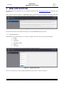
“ENORASIS” ENORASIS user manual FP7-ENV Project: ENORASIS (Grant Agreement282949) “ENVIRONMENTAL OPTIMIZATION OF IRRIGATION MANAGEMENT WITH THE COMBINED USE AND INTEGRATION OF HIGH PRECISION SATELLITE DATA, ADVANCED MODELING, PROCESS CONTROL AND BUSINESS INNOVATION” Funding Scheme: Collaborative Project Theme: FP7-ENV ENORASIS User Manual Version – issue date: 0.7 – 11/10/2013 Page i FP7-ENV “ENORASIS” ENORASIS user manual Table of Contents 1. WEB APPLICATION __________________________________________________________ 1 1.1 Registration _____________________________________________________________________ 1 1.2 Login screen ____________________________________________________________________ 2 1.3 Successful login __________________________________________________________________ 2 1.4 Generic UI and functionalities ______________________________________________________ 4 1.5 Crop types management (admin)____________________________________________________ 8 1.6 Soil types management (admin) ____________________________________________________ 9 1.7 Sensor types management (admin) _________________________________________________ 10 1.8 Users management (admin) _______________________________________________________ 11 1.9 Insert/Update Field______________________________________________________________ 12 1.10 Field view ____________________________________________________________________ 14 1.11 Insert/Update Plot_____________________________________________________________ 16 1.12 Plot View ____________________________________________________________________ 19 1.13 Insert/Update Valves __________________________________________________________ 21 1.14 Valve view ___________________________________________________________________ 22 1.15 Insert/Update Sensors _________________________________________________________ 23 1.16 Sensor view __________________________________________________________________ 24 1.17 Manually insert data for sensor __________________________________________________ 25 1.18 Manually insert data for valve ___________________________________________________ 26 1.19 Assign rights to Users __________________________________________________________ 27 Version – issue date: 0.7 – 11/10/2013 Page ii FP7-ENV “ENORASIS” ENORASIS user manual List of figures Figure Figure Figure Figure Figure Figure Figure Figure Figure Figure Figure Figure Figure Figure Figure Figure Figure Figure Figure Figure Figure Figure Figure Figure Figure Figure Figure Figure Figure Figure Figure Figure Figure Figure Figure Figure Figure Figure Figure Figure Figure Figure Figure Figure Figure Figure Figure Figure Figure Figure Figure Figure Figure 1 – Home screen ................................................................................................................. 1 2 – Registration form ........................................................................................................... 1 3 – User Type options .......................................................................................................... 2 4 – Confirmation message of successful registration ................................................................ 2 5 – Login form .................................................................................................................... 2 6 - Login error .................................................................................................................... 2 7 – Home screen of successful login – regular User ................................................................. 3 8 - Home screen of successful login - admin User.................................................................... 3 9 - My Account ................................................................................................................... 4 10 - Overview ..................................................................................................................... 4 11 - Read SOS Sensors ........................................................................................................ 5 12 - DSS Execution - Valves actions ...................................................................................... 5 13 - Universal Connector...................................................................................................... 6 14 - Rest API ...................................................................................................................... 6 15 - DSS Calculation ........................................................................................................... 7 16 – Map ........................................................................................................................... 7 17 - Map options ................................................................................................................. 7 18 - Map zooming ............................................................................................................... 8 19 - Crop types management ............................................................................................... 8 20 – Create Crop type ......................................................................................................... 8 21 – Delete Crop type.......................................................................................................... 9 22 – Soil types management ................................................................................................ 9 23 – Create Soli type ......................................................................................................... 10 24 – Delete Soil type ......................................................................................................... 10 25 - Sensor types management .......................................................................................... 10 26 – Create Sensor type .................................................................................................... 11 27 – Delete Sensor type .................................................................................................... 11 28 – User management ..................................................................................................... 12 29 – Delete confirmation .................................................................................................... 12 30 – My Fields .................................................................................................................. 12 31 – Create Field .............................................................................................................. 13 32 – Drawing the field ....................................................................................................... 13 33 – Drawing finished ........................................................................................................ 14 34 – My Fields .................................................................................................................. 14 35 – Field view ................................................................................................................. 15 36 – Related Plots ............................................................................................................. 16 37 – Create plot ................................................................................................................ 17 38 – Updated Related Plots ................................................................................................ 17 39 - Delete Plot ................................................................................................................ 18 40 – Plot View .................................................................................................................. 19 41 - View DSS Details ........................................................................................................ 20 42 - Previous DSS Results .................................................................................................. 20 43 - DSS Inputs ................................................................................................................ 21 44 - WRF DSS Inputs ........................................................................................................ 21 45 – Related Valves........................................................................................................... 21 46 – Create Valve ............................................................................................................. 22 47 – Updated Related Valves .............................................................................................. 22 48 - Related Valves ........................................................................................................... 22 49 - Valve view ................................................................................................................. 23 50 – Related Sensors......................................................................................................... 23 51 – Create Sensor ........................................................................................................... 23 52 – Updated Related Sensors ............................................................................................ 23 53 – Related Sensors......................................................................................................... 24 Version – issue date: 0.7 – 11/10/2013 Page iii FP7-ENV Figure Figure Figure Figure Figure Figure Figure 54 55 56 57 58 59 60 “ENORASIS” ENORASIS user manual – Sensor data .............................................................................................................. 25 – Related Sensors......................................................................................................... 26 - Add sensor measurements .......................................................................................... 26 – Related Valves........................................................................................................... 27 – Add water irrigation amount ........................................................................................ 27 - Field Permissions ........................................................................................................ 27 – Updated Field Permissions .......................................................................................... 28 List of tables No table of figures entries found. Version – issue date: 0.7 – 11/10/2013 Page iv “ENORASIS” ENORASIS user manual FP7-ENV 1. WEB APPLICATION The ENORASIS web application can be accessed through the URL http://app.enorasis.eu/ using any web browser. Home screen is shown in Figure 1. ENORASIS project is described in a few sentences and the Users have two options, to login in order to access the web application or to register and get a new account. Figure 1 – Home screen The About the Project menu button will lead you to the ENORASIS Project web site. 1.1 Registration Registration form is shown Figure 2. In order to register, the User need to fill all required fields: Name E-mail Password Retype password Phone User type If any filed remain empty, Save changes button will not take action. Figure 2 – Registration form The User can select one of the predifined options for User Type – shown on Figure 3. Version – issue date: 0.7 – 11/10/2013 Page 1 “ENORASIS” ENORASIS user manual FP7-ENV Figure 3 – User Type options After successful registration - Figure 4, the User can log in to ENORASIS system. Figure 4 – Confirmation message of successful registration 1.2 Login screen In order to access ENORASIS system the User need to provide correct email and password. If the User has forgotten his/her valid password, he/she can reset password by clicking on Reset password button. New password will be sent on the User email. Figure 5 – Login form If credentials are wrong, ENORASIS system will generate Error shown in Figure 6. Figure 6 - Login error The User may choose to create a new account by clicking on Create new account button. New account procedure is already described in chapter 1.1. The User may also reset password in case that he/she has forgotten it. A new password will be send on e-mail by pressing the Reset password button. 1.3 Successful login After successful login to the system the screen appears as shown in Figure 7 in case that you are a regular User or Figure 8 if you are an administrator. Version – issue date: 0.7 – 11/10/2013 Page 2 FP7-ENV “ENORASIS” ENORASIS user manual Figure 7 – Home screen of successful login – regular User Figure 8 - Home screen of successful login - admin User By clicking on the My account button in the top right corner, the User has the ability to change his/her profile data - Figure 9 Version – issue date: 0.7 – 11/10/2013 Page 3 FP7-ENV “ENORASIS” ENORASIS user manual Figure 9 - My Account 1.4 Generic UI and functionalities After successful login the accordion right menu will appear showing brief information for the following options: Overview - Figure 10 Read SOS sensors - Figure 11 DSS executions - Valves actions - Figure 12 Universal connector - Figure 13 Rest API - Figure 14 DSS Calculations - Figure 15 Figure 10 - Overview Version – issue date: 0.7 – 11/10/2013 Page 4 FP7-ENV “ENORASIS” ENORASIS user manual Figure 11 - Read SOS Sensors Figure 12 - DSS Execution - Valves actions Version – issue date: 0.7 – 11/10/2013 Page 5 FP7-ENV “ENORASIS” ENORASIS user manual Figure 13 - Universal Connector Figure 14 - Rest API Version – issue date: 0.7 – 11/10/2013 Page 6 FP7-ENV “ENORASIS” ENORASIS user manual Figure 15 - DSS Calculation One of the most important parts of this web application is the map - Figure 16. User can choose between different levels of layers by clicking on the cross sign in the right corner of the map and checking/unchecking appropriate boxes - Figure 17. Figure 16 – Map Figure 17 - Map options Zooming in and zooming out can be done by clicking on the “+” and “–” signs in the left corner, or by scrolling the mouse - Figure 18. User can move the map by clicking and dragging the map to the wanted position. Version – issue date: 0.7 – 11/10/2013 Page 7 FP7-ENV “ENORASIS” ENORASIS user manual Figure 18 - Map zooming 1.5 Crop types management (admin) The system administrator has the ability to create, edit or delete the Crop type. Figure 19 - Crop types management The Create button is located in the top right corner - Figure 19. The Create form design is shown in Figure 20. Figure 20 – Create Crop type The only field which needs to be entered is the Crop name. The administrator can change the Crop type by clicking on the Edit button located at the end of the line with the Crop name. The Crop can be deleted by the administrator by clicking on the Delete button. Message “Are you sure you want to delete this record” will appear on the screen – Figure 21. The administrator needs to confirm his decision by pressing the Delete record button. Version – issue date: 0.7 – 11/10/2013 Page 8 “ENORASIS” ENORASIS user manual FP7-ENV Figure 21 – Delete Crop type 1.6 Soil types management (admin) The system administrator has the privileges to create, edit or delete the Soil type. Figure 22 – Soil types management The Create button is located in the top right corner - Figure 22. The Create form design is shown in Figure 23. All form fields are required: Name Bulk Density Saturation Capacity The administrator can change the Soil type data by clicking on the Edit button, which is located at the end of the line of its Soil type’s name. The Soil type can be deleted by the administrator by clicking on the Delete button. Message “Are you sure you want to delete this record?” will appear on the screen – Figure 24. The administrator needs to confirm his decision by pressing the Delete record button. Version – issue date: 0.7 – 11/10/2013 Page 9 “ENORASIS” ENORASIS user manual FP7-ENV Figure 23 – Create Soli type Figure 24 – Delete Soil type 1.7 Sensor types management (admin) The system administrator has the ability to create, edit or delete the Sensor type. Figure 25 - Sensor types management The Create button is located in the top right corner - Figure 25. Create form design is shown in Figure 26. The required fields are: Name Observed Property Version – issue date: 0.7 – 11/10/2013 Page 10 FP7-ENV “ENORASIS” ENORASIS user manual The administrator can change the User data by clicking on the Edit button located at the end of the line of its sensor type’s name. Figure 26 – Create Sensor type The Sensor type can be deleted by the administrator by clicking on the Delete button. Message “Are you sure you want to delete this record?” will appear on the screen – Figure 27. The administrator needs to confirm his decision by pressing the Delete record button. Figure 27 – Delete Sensor type 1.8 Users management (admin) The system administrator has privileges to create, edit or delete the User. The Users management page is shown in Figure 28. Version – issue date: 0.7 – 11/10/2013 Page 11 “ENORASIS” ENORASIS user manual FP7-ENV Figure 28 – User management The Create button is located in the top right corner - Figure 28. The Create User procedure is the same as the Registration procedure described in chapter 1.1. The administrator can change the User data by clicking on the Edit button located at the end of the line with the name of the User. The User can be deleted by the administrator by clicking on the Delete button. Message “Are you sure you want to delete this record?” will appear on the screen – Figure 29. The administrator needs to confirm his decision by pressing the Delete record button. Figure 29 – Delete confirmation 1.9 Insert/Update Field The User can create and update the Fields by clicking on the My Fields menu option, the My Fields grid will appear as shown in Figure 30. Figure 30 – My Fields Version – issue date: 0.7 – 11/10/2013 Page 12 “ENORASIS” ENORASIS user manual FP7-ENV In order to create a new field, the User needs to click on the Create new field button in the right corner of the screen. New Create Field form will appear as shown in Figure 31. The User is expected to draw the shape of the field on exact location by clicking on the Draw button located under the map. The required fields are: Name Size Figure 31 – Create Field Optional fields are: Altitude above sea level Sensors server address Valves server address Drawing the Field is very simple. The User needs to place the mouse cursor at the desired place and to click on the left mouse button. When the shape of the Field is satisfactory the User just needs to double click on the left mouse button. In the Modify mode - Figure 32 – the User can change the shape of the Field by clicking on desired point and dragging it to the correct place. If any of points is unnecessary the User can simply delete it by placing mouse cursor over that point and clicking the Delete button on the keyboard. Figure 32 – Drawing the field If the User selects and drags the light colored point, then a new one will appear in the middle of the line, between light colored point and its neighbors and light colored point will become darker. Version – issue date: 0.7 – 11/10/2013 Page 13 FP7-ENV “ENORASIS” ENORASIS user manual When the User is satisfied with the shape and position of the field he/she just needs to press the Done button or the Reset button if he/she is completely unsatisfied. Figure 33 – Drawing finished If any changes need to be done the User can again switch to the Modify mode by clicking on the Modify button. The new field will appear in the My Fields grid - Figure 34. Figure 34 – My Fields If the User is the owner of the Field he/she can also delete the field by clicking on the Delete button located at the end of the line of its field’s name. 1.10 Field view In order to view the specific Field, the User needs to select the My Fields in the menu and then to select an appropriate Field. Web application will show five grids: Map of the Field, Related Plots, Related Sensors, Related Valves and Field Permissions as shown in Figure 35. Version – issue date: 0.7 – 11/10/2013 Page 14 FP7-ENV “ENORASIS” ENORASIS user manual Figure 35 – Field view Version – issue date: 0.7 – 11/10/2013 Page 15 “ENORASIS” ENORASIS user manual FP7-ENV The Map of the Field shows all the details about the Field. The User has two buttons: Edit for editing the shape and the field details and Delete button to delete the selected Field. The Related Plots grid offers the possibility to the User to turn on/off automatic irrigation, create, edit or delete the plot, or to click on the name of the plot and view the plot. The Related Sensors and the Related Valves are similar with their functionalities. The User can create, edit or delete the sensor/valve, or to click on the name of the sensor/valve and view them. The User can use the Field Permissions to give a privilege to any User to Read/Write or just to Read selected plot. 1.11 Insert/Update Plot In order to create the Plot, the User needs to select the Field where the Plot is located and to click on the Create button in the Related Plots grid - Figure 36 Figure 36 – Related Plots The User is expected to draw the shape of the field on exact location by clicking on the Draw button located under the map. Drawing the Plot is very simple. The User needs to place the mouse cursor at the desired place and to click on the left mouse button. When the shape of the Plot is satisfactory the User just needs to double click on the left mouse button. In the Modify mode the User can change the shape of the Plot by clicking on desired point and dragging it to the correct place. If any of points is unnecessary the User can simply delete it by placing mouse cursor over that point and clicking the Delete button on the keyboard. If the User selects and drags the light colored point, then a new one will appear in the middle of the line, between the light colored point and its neighbors and light colored point will become darker. When the User is satisfied with the shape and the position of the Plot he/she just needs to press the Done button or the Reset button if he/she is completely unsatisfied. The required fields are: Name Crop Type – drop list Soil Type – drop list Channel Type – drop list Channel Length – drop list Irrigation Method Efficiency – drop list Size in square meters Slope in degrees (degrees) Day of year of sowing (0-365) Water price (Euro/m³) Crop yield price (Euro/t) Yield without water stress (t/ha) Costs of irrigation system work (Euro/m³) Other costs of production minus subsidies (Euro/ha) Minimal profitable amount of irrigation (mm) Harvest day (0-365) Mandatory field is: Enable automatic irrigation. The new Plot will be shown in the Related Plots grid as shown in Figure 38. The User has option to change the shape of the Plot or any value from the fields listed above by clicking on the Edit button in the Related Plots grid. The User has also the ability to delete the Plot by clicking on the Delete button as Version – issue date: 0.7 – 11/10/2013 Page 16 FP7-ENV “ENORASIS” ENORASIS user manual shown in Figure 38. If the User has decided to delete the Plot he/she needs to confirm his/her decision by pressing the Delete record button – Figure 39. Figure 37 – Create plot Figure 38 – Updated Related Plots Version – issue date: 0.7 – 11/10/2013 Page 17 FP7-ENV “ENORASIS” ENORASIS user manual Figure 39 - Delete Plot Version – issue date: 0.7 – 11/10/2013 Page 18 FP7-ENV “ENORASIS” ENORASIS user manual 1.12 Plot View Figure 40 – Plot View Version – issue date: 0.7 – 11/10/2013 Page 19 FP7-ENV “ENORASIS” ENORASIS user manual In order to view the specific Plot, the User needs to click on the My Fields in the menu, to select an appropriate Field and then to click on the Plot. Web application will show five grids: Map of the Plot, DSS Results, Weather Forecast, Related Sensors and Related Valves as shown in Figure 40. The Map of the Plot shows all details about the Plot. The User has four buttons: Edit for editing the shape and the details, End Season to indicate that season is over, Start Season to indicate that season has just begun and the Delete button to delete the selected Plot. DSS Results shows the results of the Decision Support System for current day. Clicking the View DSS Details button will open page like the one shown in Figure 41. The User can go back by clicking on Show plot details button in upper right corner, or to expand grids by clicking on the Show buttons. Figure 41 - View DSS Details The expanded grids will be similar to those shown in Figure 42,Figure 43 and Figure 44. Figure 42 - Previous DSS Results The Previous DSS Results grid shows the DSS results for a previous period. The DSS Input grid shows the inputs for the DSS system coming from sensor measurements deployed from in the fields and the WRF DSS Inputs show the inputs for the DSS system coming from the weather forecast. The input data can be exported by clicking on Export DSS input data or Export WRF data buttons. Version – issue date: 0.7 – 11/10/2013 Page 20 “ENORASIS” ENORASIS user manual FP7-ENV Figure 43 - DSS Inputs Figure 44 - WRF DSS Inputs 1.13 Insert/Update Valves The User firstly needs to select a desired Field and belonging Plot. The Related Valves grid is located at the bottom of the page - Figure 45. Figure 45 – Related Valves After clicking on the Create button the Create Valves form will be open as it shown in Figure 46. The required fields are: Name Valve type – drop list Serial number API key Water flow Diameter The mandatory boxes are: Is remotely handled Takes water measurements Plots to which this valve provides data Version – issue date: 0.7 – 11/10/2013 Page 21 FP7-ENV “ENORASIS” ENORASIS user manual Figure 46 – Create Valve After filling all the fields and saving the changes, then a new valve will be listed in the Related Valves grid. Figure 47 – Updated Related Valves 1.14 Valve view The User firstly needs to select a desired Field and belonging Plot. The Related Valves grid is located at the bottom of the page – Figure 48 - Related Valves Figure 48 - Related Valves To view the valve readings the User needs to click on its name. The Valve readings are listed as graph as well as table. The User can choose the date interval to display or to export as CSV file - Figure 49. Version – issue date: 0.7 – 11/10/2013 Page 22 FP7-ENV “ENORASIS” ENORASIS user manual Figure 49 - Valve view 1.15 Insert/Update Sensors The User firstly needs to select a desired Field and belonging Plot. The Related Sensor grid is located at the bottom of the page - Figure 50. Figure 50 – Related Sensors After clicking on the Create button the Create Sensor form will be open as it shown in Figure 51. Figure 51 – Create Sensor After filling in all the fields and saving the changes the new sensor will be listed in the Related Sensors grid - Figure 52. Figure 52 – Updated Related Sensors Version – issue date: 0.7 – 11/10/2013 Page 23 FP7-ENV “ENORASIS” ENORASIS user manual 1.16 Sensor view The User firstly needs to select a desired Field and belonging Plot. The Related Sensor grid is located at the bottom of the page – Figure 53 Figure 53 – Related Sensors To view the sensor readings the User needs to click on its name. The Sensor readings are listed as graph as well as table. The User can choose the date interval to display or to export as CSV file - Figure 54 – Sensor data Version – issue date: 0.7 – 11/10/2013 Page 24 FP7-ENV “ENORASIS” ENORASIS user manual Figure 54 – Sensor data 1.17 Manually insert data for sensor If for some reason the sensor readings cannot be sent automatically, the User can do that manually. The User firstly needs to select a desired Field and belonging Plot. The Related Sensor grid is located at the bottom of the page – Figure 55. In order to insert the data manually the User needs to click on the Add measurements button. The User can enter the sensor readings manually on hourly base for that day as it is shown in Figure 56. Version – issue date: 0.7 – 11/10/2013 Page 25 FP7-ENV “ENORASIS” ENORASIS user manual Figure 55 – Related Sensors Figure 56 - Add sensor measurements 1.18 Manually insert data for valve If the User has irrigated manually, he needs to fill the data for the water irrigation amount. The User firstly needs to select a desired Field and belonging Plot. The Related Valves grid is located at the bottom of the page – Figure 57. In order to insert the data manually the User needs to click on the Add water irrigation amount button. The User needs to enter the data on hourly base for that day as it is shown in Figure 58. Version – issue date: 0.7 – 11/10/2013 Page 26 “ENORASIS” ENORASIS user manual FP7-ENV Figure 57 – Related Valves Figure 58 – Add water irrigation amount 1.19 Assign rights to Users The User firstly needs to select a desired Field. The Field Permissions grid is located at the bottom of the page - Figure 59. On the Field permissions form the User needs to fill in the email of the person that he/she wants to give an access to the selected field. One of the predefined permission options needs to be selected from the drop down menu and finally the Assign button needs to be clicked. Figure 59 - Field Permissions Granted User, its email and role will appear in the Field Permissions grid - Figure 60. Version – issue date: 0.7 – 11/10/2013 Page 27 FP7-ENV “ENORASIS” ENORASIS user manual Figure 60 – Updated Field Permissions Version – issue date: 0.7 – 11/10/2013 Page 28