1
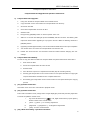
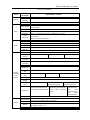
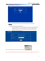
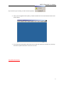
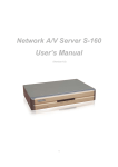
Model Number:
M4-401D1/ M4-401RW
M4-404RW/ M4-804RW
MPEG4 Embedded User Manual
Contents
Installation Guidelines.......................................................................................................4
A. Installation Environment ......................................................................4
B. Hazard Notice ..................................................................................4
Product Description...................................................................................................................5
Product Functions/ Features ...............................................................................................5
Front Panel 6
Front Panel 6
8 Channel Back Panel........................................................................................................7
4 Channel Back Panel........................................................................................................8
Remote Control.............................................................................................................. 11
System Start-up/ Shut down ................................................................................................ 13
1.
System Start up ........................................................................................... 13
2.
System Login for Setup Functions ................................................................ 13
3.
System Logoff ............................................................................................. 14
Operation Instructions ............................................................................................................. 15
Administrator Operation Instruction................................................................................... 15
1
2
3
4
5
“System” setup........................................................................................... 15
1.1
Date/ Time..................................................................................................................................15
1.2 Unit ID.............................................................................................................................................15
1.3 Video Type .......................................................................................................................................16
1.4 Audio Record....................................................................................................................................16
1.5 HDD O/W........................................................................................................................................16
1.6 HDD Format.....................................................................................................................................16
1.7 Network...........................................................................................................................................16
1.8 Security............................................................................................................................................16
1.9 1394 Settings...................................................................................................................................17
1.10 Default Setup...................................................................................................................................17
“Quick Setup” setup.................................................................................... 17
2.1 Name ..............................................................................................................................................18
2.2 Quality (Image Quality).....................................................................................................................19
2.3 Resolution ........................................................................................................................................19
2.4 Rate (fps).........................................................................................................................................19
2.5 Time Insert.......................................................................................................................................19
2.6 Mask Enable.....................................................................................................................................19
2.7 One-Step Schedule...........................................................................................................................20
2.8 Motion Detect...................................................................................................................................20
2.9 Event Record....................................................................................................................................20
“Camera” setup .......................................................................................... 21
3.1 Name ..............................................................................................................................................21
3.2 Camera............................................................................................................................................21
3.3 Quality (Image Quality).....................................................................................................................21
3.4 Resolution ........................................................................................................................................21
3.5 Rate.................................................................................................................................................21
3.6 Time Insert.......................................................................................................................................21
3.7 Mask Enable.....................................................................................................................................21
“Schedule” setup ........................................................................................ 21
4.1 ACTIVE/UNACTIVE...........................................................................................................................22
4.2 Schedule Record...............................................................................................................................22
4.3 Event Schedule ................................................................................................................................22
“Event Setup” setup.................................................................................... 22
5.1 Sensor.............................................................................................................................................22
5.2 Motion Detection ..............................................................................................................................23
5.3 Record Action...................................................................................................................................24
2
MPEG4 Embedded User Manual
6
5.4 Alarm Action.....................................................................................................................................24
5.5 Timing Setup....................................................................................................................................25
“PTZ” setup ................................................................................................ 26
6.1 All CH...............................................................................................................................................26
6.2 Protocol............................................................................................................................................26
6.3 Baud Rate........................................................................................................................................26
6.4 PTZ ID.............................................................................................................................................26
6.5 CH1 (1-8) ........................................................................................................................................26
6.6 Connect more than 1 speed dome....................................................................................................26
Playback Function Instructions.......................................................................................... 27
7
8
Playback..................................................................................................... 27
7.1 All Record.........................................................................................................................................27
7.2 Alarm Record ...................................................................................................................................28
Event Log ................................................................................................... 28
9
System Info................................................................................................ 29
Management Operation Instructions .................................................................................. 30
Compact Flash Card Upgrade and Operation Instructions ...................................................... 30
a) Compact Flash Card Upgrade............................................................................................................30
b) Compact Flash Card Backup.............................................................................................................30
c) [F1] operation instruction..................................................................................................................30
d) [F2] operation instruction..................................................................................................................30
e) [F3] “Mask area setting” operation instruction....................................................................................30
f)
[F4] VGA function operation instruction..............................................................................................31
Appendix 1 ................................................................................................................... 34
A. IDE requirement...............................................................................................................................34
B. Router Setting..................................................................................................................................34
C. Remote Client for Embedded DVR.....................................................................................................34
3
MPEG4 Embedded User Manual
Installation Guidelines
A.
Installation Environment
In order to ensure the safety and proper use of your new DVR read throw and abide by the
following guide lines.
a)
Only use with AV220V/AV110V (please notice the voltage switch on the back of transformer).
b)
Keep the DVR Away from humidity and damp areas also keep out of direct sunlight.
c)
DVR should be installed in a horizontal position.
d)
DVR should not be installed were there is excessive vibrations or ground shocks.
e)
DVR should be installed in cool and well ventilated environment.
f)
For heat transfer and ventilation purposes make sure the DVR has at least 6 inches from the
wall or any surrounding objects.
g)
B.
Ensure that the power outlet is properly wired.
Hazard Notice
a)
Do not operate the DVR with wet hands.
b)
Keep the DVR away from any areas that have potential for any liquid spills.
c)
Do not place anything on the top of the DVR.
d)
Use soft cleaners or compressed air to clean the DVR. Do not use abrasive chemical cleaners.
e)
Live voltage is still present when the DVR is plugged in, even if the DVR is turned off.
f)
Unplug the power if the DVR is not going to be used for an extended period of time.
g)
Do not try to self repair the DVR. Contact your local sales representative or technical support
if there is a system failure.
Remark: This DVR has been certified by the International Safety Standards (ISS).
5
MPEG4 Embedded User Manual
Product Description
Product Functions/ Features
l
l
l
l
l
l
l
l
l
l
l
l
l
l
l
l
l
l
l
l
l
l
l
l
l
High speed embedded CPS and real time embedded control operation system are
adapted with the DVR providing operation stability, no hang-up error, reliability and easy
for maintenance
Operation with front panel and remote control
Hardware MPEG-4 compression provides better streaming quality, support with D1,
1/2D1, CIF resolution, adjustable frame rate and provide space efficiency with small
video file size
Storage used with FAT32 format suitable for 1-2 IDE hard drive connections
For 8-Channel Provide multi-channels operation, such as
u 1-8 channels audio/video
u 2 channels video (monitor and composite) output
u 1 channel VGA output
u 1 channel audio output
For 4-Channel Provide multi-channels operation, such as
u 1-4 channels audio/video
u 2 channels video (monitor and composite) output
u 1 channel VGA output
u 1 channel audio output
8 channels alarm input with programmable settings
With several modes of surveillance display screens (Up to 1/4/8 windows per screen)
Each individual display screen with audio surveillance functions (for 4 channel only 4
audio inputs).
Time settings to activate recording system with auto switching, system re-activate after
power shut down
System alert for any video signal loss
Manual, Scheduled, or motion based recording for more effective hard disk usage
Motion detection function available with setting for 16X12 detection region area with
adjustable sensitivity detect level
Pre-setting record function and extended alert function to ensure alert information is
100% captured according to user requirements
Available for x2 and x4 fast forward/ backward function and slow motion rate at x1/2,
x1/4 and x1/8 as well as pause and frame-by-frame playback function
Availability in PAL/ NTSC modes
Individual color settings of brightness, contrast, color, motion detection settings
Complete daily report for alarm record and operation record facilitating the monitoring
station and management analysis
RJ-45 network inlet/ outlet available for the internet function for ,T1, Cable, DSL, ISDN
Using IE browser to view live cameras and playback archived videos
RS-485 connection for the platform decoder, available for different frequency settings
and decoder parameter.
PTZ Camera support from RS-485 port
VGA output
Support Compact Flash card and IBM Micro-drive disk
IEEE 1394 interface provide high speed data transfer via PC
5
MPEG4 Embedded User Manual
Front Panel
Front panel definition:
1. LED indicator status area
l
CH1~CH8: LED indicates upto 8 channels for recording status (depends on the model): LED
on = recording is in progress. LED off = the system is in standby mode. Flashing LEDS =
system is in alarm status.
l
10M/ 100M: indicator for internet speed: LED on = 100 Mbps. LED off = 10 Mbps
l
ACT/ LINK: this light indicates when the internet is connected, when the light is blinking that
means data is transferring.
2. Function Buttons
l
[ON/OFF]: Standby button.
l
[FUN]: Enable function keys on the numeric keys. When the “FUN” LED is on it means you
can access the play, exit … buttons. When “FUN” LED is off the numeric keys remain as
number keys
l
[Record]: For 8 channel surveillance system it can activate 8 channel manual
recording. For 4 channel surveillance system it can activate 4 channel manual
recording
l
[Stop]: Stop manual recording
l
[Login/Lock]: Login to enter to setup mode (must use password)
l
[Review]: Checking the recording information, event logs, hard disk status,
firmware version etc.
l
[Play]: Playback the recorded video
l
[Setup]: Setting the DVR configuration and parameters
l
[Exit]: Back to operation screen from setup menu/ or goes to the previous step
in the menu
l
[Display]: Starts and pauses playback (still image is displayed)
l
[Stop/Pause]: Slow play, slow motion rate at x1/2, x1/4 and x1/8.
l
[CF Card]: Compact Flash Card slot for upgrade and backup function
l
[Stop/Pause]: press one to pause, press again to play single frame
l
[1394]: 1394 connection port
6
MPEG4 Embedded User Manual
8 Channel Back Panel
Back panel definition:
1.
Ventilation fan
2.
110V/220V switch (!! WARING: MAKE SURE TO USE THE PROPER VOLTAGE BEFORE
CONNECTING THE POWER!!!)
3.
Power connection
4.
Audio input: provide 8 channels audio input
5.
Audio output: 1 channels for audio output
6.
Video input: Channel 1~8 for video signal input
7.
Video output: 2 channels for video signal output.
8.
VGA: output with external computer monitor
9.
RS-232: Standard RS-232 connection
10. Internet interface
11. Ventilation fan for main unit
12. Alarm signal in/ out/ RS-485: 8 channels input/ output,2 channels fault report output / RS485
signal / PTZ control
7
MPEG4 Embedded User Manual
4 Channel Back Panel
Back panel and connection outlet:
1.
Power socket Intel
2.
110/220 switch (!! WARNING: MAKE SURE TO CHECK THIS OUT BEFORE CONNECT
POWER!!!)
3.
Ventilation fan
4.
Audio input: provide 4 channels audio input
5.
Audio output: 2 channels for audio out
6.
Video output: 2 channels for video signal output:
7.
Video input: Channel 1~4 for video signal input
8.
VGA: output with external computer monitor,
9.
RS-232: Standard RS-232 connection
10.
Internet connection
11.
Ventilation fan for main unit
12.
Alarm signal in/ out/ RS-485: 4 channels input/ output
8
MPEG4 Embedded User Manual
MPEG4 Alarm
connector pin
definition
Pin
DEF
Function
Pin
DEF
1
IN0
Channel 1 Alarm input
19
7COM
2
IN1
Channel 2 Alarm input
20
7NO
3
IN2
Channel 3 Alarm input
21
7NC
4
IN3
Channel 4 Alarm input
22
8COM
5
IN4
Channel 5 Alarm input
23
8NO
6
IN5
24
8NC
7
IN6
25
485A
8
IN7
26
485B
9
OUT0
10
OUT1
11
OUT2
12
OUT4
13
5COM
14
5NO
15
Channel 6 Alarm input
Channel 7 Alarm input
Channel 8 Alarm input
Channel 1 Alarm output
Channel 2 Alarm output
Channel 3 Alarm output
Channel 4 Alarm output
27
485GND
28-34
GND
35
9COM
36
9NO
37
9NC
38
9COM
5NC
39
9NO
16
6COM
40
9NC
17
6NO
41-44
+12V
18
6NC
Channel 5 Alarm output
Channel 6 Alarm output
Function
Channel 7 Alarm Output
Channel 8 Alarm Output
Connect for platform decoder
\sensor A
Connect for platform decoder
\sensor B
Connect to platform decoder
\sensor GND
Ground
Power fault report output
Fault report output
+12V/1A
9
MPEG4 Embedded User Manual
4 channels alarm layout definition:
u
1-2 channels for open socket switch output. No need for additional alarm driver
u
3-4 channels for power levels output. OUT for low power out. Require additional alarm device.
1-2 channel connections layout(no alarm status) 3-4channel connections layout(no alarm status
10
MPEG4 Embedded User Manual
Remote Control
LOGI N/ LOCK
POWER ON
PLAYBACK
1
2
3
4
5
6
7
8
9
+
0
QUAD
PARAMETER
ANALOG
ZOOM+
ZOOM-
FOCUS-
FOCUS+
EXI T
AUTO
RECALL PRESET SWI TCH
PLAY
SLOW
CF
FWD
REV
NET
RECORD
STOP
F1
F2
SET UP
F3
F4
Remote Control Key Definition/ Function:
11
MPEG4 Embedded User Manual
a.
Numeric Keypad:
[0-9] keys: During setup, number input keys are used to select values.
For viewing channels 1, 2, 3 and 4 use 1, 2, 3 and 4 on numeric keypad respectively.
[+], [-] keys: During setup, plus and minus are used to select next or previous values.
During video playback, these keys control audio playback volume levels.
b.
Menu Operation:
▲, ▼: Up, down directional keys: Moves selection up and down in setup menu.
►, ◄: Left, Right directional keys: Moves cursor left or right in setup menu.
[ENTER] key:
During setup, select and save entry.
During live view, displays time on screen
c.
PTZ Platform Control Keys [F2]:
Key
[Zoom In +], [Zoom Out -]
[Brightness +], [Brightness -]
[Focus +], [Focus -]
[Auto]
[Manual]
[Default]
[Window Wiper/Lighting]
Definition
Zooming adjustment
Brightness adjustment
Image Focus adjustment (if applicable)
Auto Mode activate (if applicable)
Manual Adjustment Platform (if applicable)
Use with Default configuration
Control with window rain wiper and lighting (if
applicable)
d. Other Key Definition:
[POWER ON]
DVR turn on and off (Standby and Start)
[LOGIN/ LOCK] KEY
When a password is required (selected in setup) to activate control of the
DVR from the handheld, press LOGIN/LOCK to enter the password to unlock
the unit or to lock it again.
[CHECK/PLAYBACK]
Displays the HD information on how much storage is left
[QUAD]
Swapping between multi-channel and single channel monitor
While in surveillance screen.
[PARAMETER]
Display the parameter for each channels
[ANALOG]
Stop the recording and while in signal channel screen, press this button to
adjust the color, brightness. Contrast, Hue, sensitivity level, follow with:
color→ brightness → contrast → Hue → MD (Motion detection) sensitivity.
[ using “+” and “–“ make the adjustment]
[EXIT]
Returns to the previous menu. Ultimately exit the setup menu and return to
the live monitor screen
[PLAY]
Starts and pauses playback (still image is displayed when the image is
paused)
[SLOW]
Reduces playback speed to ½ normal.
Press EXIT to return to normal
playback speed
[PAUSE/STEP]
Freezes playback to a single frame and can advance one frame at a time.
Press EXIT to return to normal playback speed
[CF]
[FWD]
While CF card inserted, button is used to activate the CF function
Fast forward. X2 and X4 speeds available. Press [play] to resume normal
playback
12
MPEG4 Embedded User Manual
[REV]
Fast backward. X2 and X4 speeds available. Press [play] to resume normal
playback
[NET]
Spared button/no function
[RECORD]
Manual recording
[STOP]
Stop for playback / recording
[SETUP]
System setting screen (may require login)
[F1]
Time select while in playback mode
[F2]
PTZ Platform control function
[F3]
Press this button to setup the Mask area while in surveillance mode
[F4]
Switch between composite / VGA output
System Start-up/ Shut down
1.
System Start up
1.1
Please ensure that you have switched to the correct power mode. Connect to AC power outlet
and press the stand by power on button. The system will begin the boot up sequence.
1.2
After the system is in stand by mode, press the [ON/OFF] button on front panel or remote
control, the red light will turn off and monitor will be activated to show the surveillance cameras.
There will be a channel number to indicate each input signal.
1.3
The system time will be shown on top of the screen, number of hard disk and CF card status
would also be displayed in the center of the screen (there will be an alert warning if no hard disk
is installed or formatted). The information will display on the screen for 5~6 seconds.
1.4
A count down will automatically start from 100 to 0 seconds (shown in red color). The system
will be locked after the count down reaches 0 seconds.
Notice: If the DVR is being set for timer record function there is no need for standby status after the system
is turned on.
2.
System Login for Setup Functions
Should the unit have password authorization enabled in order to enter setup functions, there will be no
response from the handheld until the authorized password is entered. To enter a password:
•
Press the LOGIN/LOCK key on the handheld controller
•
When a menu appears on the display, enter the Unit ID and stored password (Default unit is 000
and password is 88888888)
Press ENTER on the handheld controller. If the password is accepted, the setup menu will appear.
13
MPEG4 Embedded User Manual
•
When password key is correctly entered, the count down timer (shown on top right corner)
will change from a red to a green color indicating access granted to different operations.
There will be 100 seconds of operation time allowed after every key button is pressed
before the system will automatically go into lock mode. Users will be required to re-enter
the password to regain access back into the DVR operations level once the “LOCK”
indicator is reactive and will be shown in top right hand corner.
Two levels of password are available in the setup. Depending on the authorization assigned to the password
entered, the permissions for the entered password will display on the screen:
•
USER PASSWORD CORRECT indicates permission is limited to playback of recorded
video.
•
ADMIN PASSWORD CORRECT indicates full access to all playback, setup and controls.
** The unit has a built in SUPER Password, in case the ADMINISTRATIVE password does not work. It is a
back door entry to the unit which cannot be changed. The password is 19810512. IT IS HIGHLY
RECOMMENDED THAT THIS PASSWORD IS RECORDED AND STORED IN A SAFE PLACE.
3.
System Logoff
Press the [Login/Logoff] button on the front panel or remote control after the record stop button is
pressed. The system will go into standby mode.
Note: Please make sure the DVR system status is in standby mode before powering off.
Avoid any
improper shut down operations. Please do not power off the machine while recording/ playback/ or system
settings are running.
14
MPEG4 Embedded User Manual
Operation Instructions
Administrator Operation Instruction
When the administrator enters into the setup menu this screen will show following menu selections:
M4-404RW/M4-804RW
System
System
Quick
Quick Setup
Setup
M4-401D1/M4-401RW
Camera
Camera
Schedule
Schedule
Event
Event Setup
Setup
PTZ
PTZ
Note: Camera setup not available for M4-401D1/M4-401RW
[Left] [Right] Keys navigate through the items. [Enter] Key selects the option.
[EXIT] or [SETUP] takes back to the camera monitor screen.
1
“System” setup: The menu will be displayed as below:
System
System
Quick
Quick Setup
Setup
Camera
Camera
Schedule
Schedule
Event
Event Setup
Setup
Date / Time
08/09/2004, Wednesday
Unit ID
18:00:30
Video Type
Date Mode
dd/mm/yyyy
Audio Record
Weekday Start
MON
HDD O/W
Weekday End
FRI
PTZ
PTZ
HDD Format
Network
Security
1394 Settings
Default Setup
Apply
Apply
1.1
Date/ Time: Press ENTER to access input settings. Use ARROW keys to scroll
Date:
DD/MM/YYYY
Enter with number keys
Time:
HH/MM/SS
Enter with number keys
Date Mode: (US or Int’l)
Press ENTER to switch between the date patterns
Weekend Start: (Day Name)
Press ENTER to advance days
Weekend End:
Press ENTER to advance days
(Day Name)
Scroll to APPLY and press ENTER to save the new settings.
1.2
Unit ID: Use the NUMERIC keypad to enter the unit ID between 000 to 999. This ID is used
when logging in to the unit (if security is enabled).
Scroll to APPLY and press ENTER to save the new settings.
15
MPEG4 Embedded User Manual
1.3
Video Type: Select the appropriate camera signal type. Select between “NTSC” (US) or “PAL”
(International) standards of video recording.
Scroll to APPLY and press ENTER to save the new settings.
1.4
Audio Record: Enable / Disable for the audio record for each camera channel.
Scroll to APPLY and press ENTER to save the new settings.
1.5
HDD O/W: Press ENTER to switch between “ON” and “OFF”. When the overwrite feature is
turned “ON”, recordings will always continue to be added with the oldest recording being erased
to make room for the newest recording. When the overwrite feature is turned “OFF”, recording
will stop when the disk becomes full. You must erase all the recordings using the Setting “HDD
Format” to resume recording.
Scroll to APPLY and press ENTER to save the new settings.
1.6
HDD Format: This option allows formatting the hard drive. Select the desired hard drive and
press Start.
WARNING!!!
Selecting START on this setting will deleted all recorded video. Press
ARROW keys to either choose START reformatting the disk or choose RETURN without
formatting.
1.7
Press ENTER to format or return. Press EXIT to return to the settings.
Network: You must enter a static IP address to use Network capabilities. Please talk to
your local Internet Service Provider for the information. Use NUMERIC keypad to enter the
TCP/IP address information:
Setup “IP address”:
Enter the static IP address
Setup “Mask”:
Enter the subnet mask
Setup “Gateway”:
Enter the gateway
Setup “MAC Address”:
Enter the MAC address of your device (optional)
Scroll to APPLY and press ENTER to save the new settings
1.8
Security: “YES” will require a password in order to access the setup menu. Selecting “NO” will
not require a password in order to access the setup menu.
a. Security: Selecting “YES” will require a password in order to access the setup
menu. Selecting “NO” will not require a password in order to access the setup
menu. An Administrator with full rights and a User with only playback rights can
be created.
b. Press ENTER to switch between “YES” and “NO”.
c.
Press the down ARROW key to highlight the User password entry line. Enter the
desired password and confirm. The password must be EIGHT NUMBERS long.
Use the NUMERIC keypad on the handheld to input the values.
d. Press the down ARROW key to highlight the administrator password entry line.
Enter the desired password and confirm. The password must be EIGHT
16
MPEG4 Embedded User Manual
NUMBERS long. Use the NUMERIC keypad on the handheld to input the values.
** The unit has a built in SUPER Password, in case the ADMINISTRATIVE password does not work. It is a
back door entry to the unit which cannot be changed. The password is 19810512. IT IS HIGHLY
RECOMMENDED THAT THIS PASSWORD IS RECORDED AND STORED IN A SAFE PLACE.
1.9
1394 Settings: Select “Close” and press “APPLY” it’ll close the 1394 function. Select “Open
Group 1” and press “APPLY”. To exit the menu press “EXIT” and the DVR will restart (this means
the 1394 function is activated). Select ‘RETURN” and press “ENTER”; the DVR will cancel the
activate function and return to previous menu.
System
System
Quick
Quick Setup
Setup
Camera
Camera
Schedule
Schedule
Date / Time
Close
Unit ID
Open Group 1
Video Type
Open Group 2
Audio Record
Open Group 3
HDD O/W
Open Group 4
HDD Format
Return
Event
Event Setup
Setup
PTZ
PTZ
Network
Security
1394 Settings
Default Setup
1.10
Default Setup: User ARROW keys to switch between “YES” and “NO”. Selecting YES will restore
the default factory settings.
Scroll to APPLY and press ENTER to save the new settings
2
“Quick Setup” setup : The menu will be displayed as below:
(For M4-404RW/M4-804RW)
17
MPEG4 Embedded User Manual
System
System
Quick
Quick Setup
Setup
Camera
Camera
Name
Schedule
Schedule
Event
Event Setup
Setup
PTZ
PTZ
Exhibition Center
Quality (1 high~8 low)
1
Resolution
HD1
Rate (fps)
Time Insert
Upper
Mask Enable
One-Step Schedule
Period 1
Period 2
MON
00:00 - 23:59
13:45 - 18:55
SAT
06:45 - 12:00
-- : -- - -- : --
Motion Detect
OFF
Event Record
OFF
8
ON
Apply
Apply
(For M4-401D1/M4-401RW)
2.1
Name: Select the option and press “enter”. The screen will display an on-screen keyboard.
Using “Back space” to delete the old name and select a desired name (limit up to 6 characters)
for the site.
Scroll to APPLY and press ENTER to save the new settings.
18
MPEG4 Embedded User Manual
System
System
Quick
Quick Setup
Setup
Camera
Camera
Name
Schedule
Schedule
Event
Event Setup
Setup
PTZ
PTZ
Main Buildin
Apply
Apply
2.2
Quality (Image Quality): Press ENTER to enter the recording quality (1 is the highest quality)
2.3
Resolution: Select between HD1 or CIF
2.4
Rate (fps):
2.5
Press ENTER to choose between:
u
8, 15, or 30 frames/second (for NTSC)
u
6, 12, or 25 frames/second (for PAL)
Time Insert: Press ENTER to switch between “ON” and “OFF” to embed time/date on the
screen
2.6
Mask Enable:
”ON”: allows the user to setup the mask area
”OFF”: does not all the user to setup the mask area
2.6.1 Once Mask is enabled, you be taken to the Mask area setup screen and here you can see
that there are white block shown (as the starting point) See Below:
2.6.2 Then you can move your cursor to select the area to cover (Press “Enter” to place the area
Minimum 3 points will need to be placed, after completing the cover areas, press the
“Enter” button twice).
19
MPEG4 Embedded User Manual
2.6.3 Mask setting can be into other irregular shapes as shown:
2.7
One-Step Schedule:
Press ENTER to change the period of time to control the recording schedule
Single Day:
Choose the name of a day to create a recording schedule
Every:
Choose “Every” to apply a schedule to every day of the week
Weekday:
Schedule will only apply Weekdays (weekday start and weekday
end can be defined in the SYSTEM tab)
**********:
2.8
Choosing the asterisks will suspend the highlighted schedule
Motion Detect=OFF: Once in the “Quick Setup” Mode the settings will be automatically
disabled for the motion detection
2.9
Event Record=OFF: This will automatically disable the even recording function.
20
MPEG4 Embedded User Manual
3
“Camera” setup: The menu will be displayed as below:
(Only available on Models M4-404RW/M4-804RW)
System
System
Quick
Quick Setup
Setup
Camera
Camera
Schedule
Schedule
Event
Event Setup
Setup
ALL CH
Name
WAREHOUSE
CH 1
Camera
ON
CH 2
Quality
1
Resolution
HD1
Rate (fps)
8
Time insert
Upper
Mask Enable:
ON
CH 3
CH 4
PTZ
PTZ
CH 5
CH 6
CH 7
CH 8
Apply
Apply
3.1
Name: Type in the title for each camera to appear on the video display. The name is embedded
with the video
3.2
Camera: Enable the current camera by switch from OFF to ON
3.3
Quality (Image Quality): Press ENTER to enter the recording quality (1 is the highest quality)
3.4
Resolution: Select between D1,HD1 or CIF
3.5
Rate (fps): Press ENTER to choose between:
3.6
u
8, 15, or 30 frames/second (for NTSC)
u
6, 12, or 25 frames/second (for PAL)
Time Insert: Press ENTER to switch between “ON” and “OFF” to embed time/date on the
screen
3.7
Mask Enable:
”ON”: allow you to setup the mask area
”OFF”: Does not allow you to setup the mask area
Once Masking is enabled, you will enter into Mask area setup screen, then you can move your
cursor to select the Masked area (Press “Enter” to place the point. Minimum 3 points needed).
After masked areas are complete press the “Enter” key twice to form the areas.
4
“Schedule” setup: The menu will be displayed as below:
21
MPEG4 Embedded User Manual
System
System
Quick
Quick Setup
Setup
Camera
Camera
Schedule
Schedule
Event
Event Setup
Setup
CH
CH 11
PTZ
PTZ
UNACTIVE
UNACTIVE
Schedule Record
Event Schedule
Schedule Table
Days
Period 1
Period 2
MON
07:00 : 12:00
13:45 : 18:55
MON
20:15 : 22:00
22:20 : 23:45
For M4-401D1/M4-401RW label
TUE
09:15 : 11:30
14:00 : 22:00
“Time Schedule Record”
WED
07:00 : 12:00
13:45 : 18:55
Weekday
05:45 : 06:10
-- : -- : -- : --
Weekday
12:15 : 12:20
13:15 : 13:30
SAT
06:45 : 12:00
-- : -- : -- : --
Weekday
09:15 : 11:30
14:00 : 22:00
Apply
Apply
Select the channel for schedule setting.
4.1
ACTIVE/UNACTIVE: Enables/Disables the schedule recording per channel
4.2
Schedule Record: This menu allows you to set the recording conditions by channel and time
schedule. If you have setup the Schedule Record the “Quick Setup”, changing the setting value
in this menu will replaces the previous settings
4.3
Event Schedule (Record): This menu is to set the detailed event recording conditions. It is
necessary to set the “Event Record” menu to “YES” to enable the DVR to record events in “Quick
Setup”
5
“Event Setup” setup: The menu will be displayed as:
System
System
Quick
Quick Setup
Setup
Camera
Camera
Schedule
Schedule
Sensor
ALL CH
Motion Detect
Configuration (press Enter for selection)
Record Action
Not available for DVR
M4-401D1/M4-401RW
Event
Event Setup
Setup
PTZ
PTZ
OFF
Sensor
Sensor
Alarm Action
S1
N.O.
S5
OFF
Timing Setup
S2
N.C.
S6
N.O.
S3
OFF
S7
N.C.
S4
OFF
S8
OFF
Apply
Apply
5.1
Sensor: This menu is to set the input sensor. The sensor supports two types: Normal Open (N.O)
and Normal Close (N.C). If you set the recording conditions to All Ch, “Macro Setup” is displayed.
22
MPEG4 Embedded User Manual
If you change any one of the individual sensor settings “Customer Setup” is displayed.
ALL CH: Sets all the sensors to the same conditions. Select from Off/ N.O. / N.C. and then press
the “Apply” button
5.2
Motion Detection (MD):
System
System
Quick
Quick Setup
Setup
Camera
Camera
Schedule
Schedule
ALL CAM
Event
Event Setup
Setup
PTZ
PTZ
OFF
Sensor
Motion Detect
Configuration (press Enter for selection)
Record Action
MD
Alarm Action
Set All
Area
Set
MD
Cam 1
AR
Cam 5
OFF
Cam 2
OFF
Cam 6
OFF
Not available for
Cam 3
NR
Cam 7
OFF
M4-401D1/M4-401RW
Cam 4
OFF
Cam 8
OFF
Timing Setup
Set
All
Area
Set
Apply
Apply
5.2.1 Sets all cameras to the same condition: Select from OFF/ NR/ AR. (Normal Recording)/ AR
(Alarm Recording )[setting refer to section 5.4]
5.2.2 Sets the Channel Motion Detection (MD) Area: You can directly set the MD Area on the
screen. To choose whole screen as motion detection by pressing “Set All” to activate it.
Press the “AREA Select” button, a setup window divided into 192 blocks [16(H)X12(V)] will
be display
5.2.3 Select the desired MD area using the arrow buttons and using “Analog” button on the
handheld remote controller to adjust MD sensitivities from 1 to 16 levels. (1 is the highest
sensitivity 16 is the lowest)
5.2.4 The red flashing block is for moving selections trigger this with the “Enter” button for select
and un-select block for MD. Once the blocks have been selected they will appear as “Green”
5.2.5 Also you can select different sections for motion detection for example:
23
MPEG4 Embedded User Manual
5.2.6 When objects are moving into the defined area, it will appear as red color for example:
5.2.7 Press the “Exit” button to exit the MD setting and return to the previous menu
5.3
Record Action: (Not available for DVR M4-401D1/M4-401RW) This is the matrix setting that
will allow the alarm senor to activate recording action at selected channels. For example: we can
setup Port 1 alarm to activate the Channel 1 and Channel 4 start to recording. Port 3 alarm to
activate the Channel 1, 2 and 4 recording action. The senor ports available for 4 inputs for 4
channels DVR and 8 inputs for 8 channels DVR. See example as below:
System
System
Quick
Quick Setup
Setup
Camera
Camera
Schedule
Schedule
Event
Event Setup
Setup
ON
ON
Record Action Setting
Sensor
Port
PTZ
PTZ
Activate Record Channel (s)
Motion Detect
1
Record Action
Alarm Action
Timing Setup
2
3
4
5
6
7
8
Port 1
Port 2
Port 3
Port 4
Port 5
Port 6
Port 7
Port 8
Apply
Apply
5.4
Alarm Action: (Not available for DVR M4-401D1/M4-401RW) This is the matrix setting that
allows the alarm senor to activate alarm signal to selected output port. For example: we can
24
MPEG4 Embedded User Manual
setup Port 1 alarm to activate the port 1 and port 4 start to alarm signal. Port 3 alarm to
activate the port 1, 2 and 4 alarm signal action. The senor ports available for 4 inputs/ 6 outputs
for 4 channels DVR and 8 inputs/10 outputs for 8 channels DVR. See example as below:
System
System
Quick
Quick Setup
Setup
Camera
Camera
Schedule
Schedule
Event
Event Setup
Setup
ON
ON
Alarm Action Setting
Sensor
Port
PTZ
PTZ
Activate Alarm Channel (s)
Motion Detect
1
Record Action
2
3
4
5
6
7
8
Port 1
Alarm Action
Port 2
Timing Setup
Port 3
Port 4
Port 5
Port 6
Port 7
Port 8
Apply
Apply
5.5
Timing Setup: Allow settings the following parameters:
System
System
Quick
Quick Setup
Setup
Camera
Camera
Schedule
Schedule
Event
Event Setup
Setup
PTZ
PTZ
Timing Setup
Sensor
Per Record Time (0~300S)
AUTO
Record Action
Post Record Time (120~300S)
10
Alarm Action
Post Alarm Time (0~300S)
05
Buzzer Alarm Time (0~300S)
10
Motion Detect
Timing Setup
Apply
Apply
5.5.1 Pre Record Time: This shows as “AUTO” (not allowing for adjustments) due to factory
setting the default pre 10 seconds and post for 10 seconds ahead from the time of start
recording (such as Motion Detection. Once it is activated then the video record is 10
seconds ahead of the Motion being detected)
5.5.2 Post Record Time: Extend time for recording action after certain criteria is met (such as
alarm senor to activate the Channel 1 for recording then this will start record at certain of
time in this setting)
5.5.3 Post Alarm Time: Time to send the alarm signal once the criteria has been met (such as
Motion Detection)
5.5.4 Buzzer Alarm: Time duration for buzzer alarm
25
MPEG4 Embedded User Manual
6
“PTZ” setup: The menu will be displayed as:
System
System
Quick
Quick Setup
Setup
Camera
Camera
Schedule
Schedule
Event
Event Setup
Setup
PTZ
PTZ
PTZ Setup – ALL CH
ALL CH
Protocol
Pelco-D
CH 2
Baud Rate
9600
CH 3
PTZ ID (00 ~ 64)
05
CH 1
CH 4
CH 5
Test
Test
Apply
Apply
CH 6
CH 7
CH 8
M4-401D1/M4-401RWl only
display the first 4 channels
6.1
All CH: If “all ch” is selected user can setup the Protocol, Baud Rate, and PTZ ID for all the
available channels in the DVR. 16 different PTZ-protocols are available
6.2
Protocol: select different protocols for Fast Speed Dome
6.3
Baud Rate: select the different baud rates for selected protocol at: 1200, 2400, 4800, 9600
6.4
PTZ ID: select ID between 0-64
Select [Test] button and the screen will show in a single play mode, the [House control] also
show at upper of the screen.
Using the remote control or front panel to control the platform:
: For up direction
: For down direction
, For Left direction
: For Right direction
Zoom +/ Zoom -: For zooming in and zooming out
Brightness + / Brightness -: For brightness adjustment
Auto: Auto Mode
6.5
CH1 (1-8): when move to this item it can only setup the PTZ ID of the 1CH.
Remark: The parameter of “Protocol”; “Baud Rate”; “PTZ ID” must the same as the setting of
connected Speed Dome.
6.6
Connect more than 1 speed dome: (See connection diagram)
26
MPEG4 Embedded User Manual
Playback Function Instructions
Playback Function Instruction: User must have administrative rights for the search function to
work. Press the [Check] button of the handheld remote controller. Following screen will appear on the
screen:
Record
Record Playback
Playback
7
Event
Event Log
Log
System
System Info
Info
Playback: The menu will be displayed as:
Record
Record Playback
Playback
All Record
Event
Event Log
Log
System
System Info
Info
Playback all record
Alarm Record
Channel
02
Date
2004-10-20
Time
00:00
Start
Start
7.1
Return
Return
All Record: Using the numbers from the handheld controller and arrow keys to advance to the
next field, enter the following data:
”Channel”:
Enter the desired channel to playback
“Year”:
Range is 2000 to 2099. Only uses the last 2 digits of year (eg: “03” for year 2003)
“Month”:
Range is 01-12 for the appropriate month number
“Day”:
Range 01-31 for the appropriate day for the recording search
“Hour”:
Range 00-23 for the appropriate hour to begin the search
“Minutes”:
Range 00-59 to narrow the search beginning to an exact minute
A calendar will appear as below. The yellow color indicated the days of recording. The blue color
indicates no recording.
27
MPEG4 Embedded User Manual
Date: 2005-01-31
1
2
3
4
5
6
7
8
9
10
11
12
13
14
15
16
17
18
19
20
21
22
23
24
25
26
27
28
29
30
HD1
HD1
HD1
30
30
30
1
1
1
Streamin
Streamin
Streamin
00:00-00:30
00:00-00:21
00:34-00:38
M
M
M
31
Return
Return
Start
Start
For M4-401D1/M4-401RW
Example:
”Date”: Shows the date you selected
“1”: The channel number
“Streamin”: The channel name
“00:00-00:30”: The recorded data start and end time
“M”: Recording mode (M: manual record A: Alarm record R: Timing record)
“HD1”: Picture resolution (D1,HD1 or CIF)
“30”: Shows the number of frames
7.1.1 To access recorded video select the file and press “Enter”. The DVR will start to playback the
recorded video.
7.1.2 While in playback press [F1] button a pop screen will show the following selection:
Time
00:00-00:00
Start
Return
7.1.3 This menu is for searching the time and playing back the data of a specific time. From the
starting time of the saved data. To the ending time of the saved data.
7.1.4 Press the [Exit] button to close the search mode.
7.2
Alarm Record: Selecting this option will show the alarm record data. Select the desired event
and press [Start] to playback
8
Event Log: The menu will be displayed as:
28
MPEG4 Embedded User Manual
Record
Record Playback
Playback
Event
Event Log
Log
Alarm Log
System
System Info
Info
Alarm Log Browser
Operate Log
Date
Time
Cause
2004/08/26
07:00:19
Video Loss
2004/08/27
15:23:55
MD
2004/09/03
10:44:03
Video Loss
2004/09/10
22:39:29
Wrong PW
2004/09/15
08:00:00
Video Loss
2004/09/16
16:10:00
Alarm 1
2004/09/20
00:08:03
Wrong PW
2004/09/21
05:24:13
Video Loss
PageUP
PageUP
PageDown
PageDown
Page1
Page1 of
of 33
Alarm Log: Displays the alarm log information
Operate Log: Displays the DVR operation log information
9
System Info: The menu will be displayed as:
Record
Record Playback
Playback
Channel Info
Event
Event Log
Log
System
System Info
Info
Channel Overview Status
Hard Disk Info
Channel
Status
Q
Size
Frame
Alarm
Motion
Detect
1
Record
3
D1
08
Idle
Open
2
Idle
2
D1
08
Idle
Open
3
Idle
2
D1
08
Idle
Close
4
Play
3
D1
08
Idle
Open
5
Record
1
HD1
15
Idle
Close
6
Record
1
HD1
15
Idle
Open
7
Record
3
D1
08
Idle
Close
8
Idle
3
CIF
30
Idle
Open
Machine Info
PageUP
PageUP
PageDown
PageDown
Page1
Page1 of
of 22
Channel Info: Display all the channel status
Hard Disk Info: Display all Hard disk information
Machine Info: Display DVR ID No, Serial No, and the firmware version Number
29
MPEG4 Embedded User Manual
Management Operation Instructions
Compact Flash Card Upgrade and Operation Instructions
a)
Compact Flash Card Upgrade:
1.
Using a PC format the Compact Flash card in FAT32 format
2.
Copy the latest version of firmware into Compact Flash root directory
3.
Shut down the DVR
4.
Insert the Compact Flash card into CF Slot
5.
Start the DVR
6.
Keep pressing [ON/OFF] button on the front panel of the unit
7.
Within 2~3 seconds the LED light (SYS and POWER) will start to flash. The flashing LED
represents the firmware upgrading is in progress. Once the LEDs are flashing release the
[ON/OFF] button
8.
Upgrading will take approximately 1 minute and both the LEDS will turn off upon completion
9.
Turn off the device to remove the Compact Flash card from the slot
10.
Restart the device and the new firmware should be loaded without changing the user
settings
b)
Compact Flash Card Backup:
In order to copy the data from DVR into Compact Flash card please follow these instructions.
1.
Shut down the DVR
2.
Insert the Compact Flash card into CF Slot
3.
Start the DVR
4.
Once the boot sequence is completed successfully stop all recording activity
5.
Pressing [CF Card] button on the remote control or front panel will allow for copying all
required information and data into the Compact Flash Card
6.
Re-Pressing [CF Card] button on the remote control or front panel will stop the copying
process
c)
[F1] operation instruction:
This button menu is for time select while in playback mode
d)
[F2] operation instruction
In the main surveillance mode, change it into a single display play mode and press the [F2] button
to access the platform control menu:
i.
Up, Down directional keys
,
:
Left, Right directional keys press [Enter]
button to back to the normal status
e)
ii.
[Zoom +]; [Zoom -]: for zooming adjustment
iii.
[Brightness +]: [Brightness -]: for brightness adjustment
iv.
[Auto]: for auto mode activates
[F3] “Mask area setting” operation instruction:
30
MPEG4 Embedded User Manual
This function is for the mask area setting. After log in change the main screen into a single display
play mode. Press the [F3] button to startup the mask settings. Press the [Enter] button to display
a white square on the screen. Using the directional keys to move the white square to select the
area and then press the [Enter] button. Select up to 4 points on the white square to make up the
region for the coverage set area. Press then [Enter] button to confirm the setup and press [EXIT]
to go back to the surveillance mode.
f)
[F4] VGA function operation instruction:
In surveillance mode, press the [F4] button of remote control to swap between Composite and
VGA output. Pressing the F4 button three times will switch to the VGA mode. Pressing the F4
button once will switch back to composite mode.
31
MPEG4 Embedded User Manual
Technical specification
Item
System
Device
Parameter
UI Language
User
Interface
Security
Video Input
Video Output
Video
Video Display
Video
Standard
System
Resource
Audio
Audio Input
Audio Output
Basic output
S/N
Recording
Format
Compression
Encoding
Image
Format
Video
Standard
Audio
Standard
Video Freq.
Audio Freq.
Digital
Processing
and
Storing
Audio Size
Rate
Video Size
Rate
Storage
Image
Quality
Max Frame
Rate
Resolution
Data capture
Motion Detect
Alarm
Input
Output
Alarm mode
Specification / Details
English
Icon operation interface (OSD menu)
User level password and administrator level password
8 channels independent input with 1.0Vp-p,75Ω BNC
2 PAL/NTSC output with 1.0Vp-p,75Ω BNC; composite video signal
1 VGA output
1/4/8 windows per screen
PAL:
25 frames per second CCIR625 lines 50 Hz
NTSC: 30 frames per second CCIR525 lines 60 Hz
8 channels real time recording with 1 channel playback and 8 channels
surveillance
Online real time surveillance
8 channel input,L, R Channels 600Ω RCA
1 channel surveillance/ playback audio output,
1.0—2.2V
≤-30dB
Synchronous with video
600Ω
PCM
MPEG-4 Variable encode rate \ Fixed encode rate
1/2D1: 704x288 pixels
D1: 704x576 pixels
RCA
CIF: 352x288 pixels
ISO14496
ISO11172
12.5K-112.5Kbytes
8Kbyte/s
25K-150Kbyte/s
50K-300Kbyte/s
90M-540Mbyte/hour
180M-1080Mbyte/hour
28.8Kbyte/s
45M-405Mbyte/hour
8 IDE hard disk,support 200G or larger
8 Adjustable levels
25 frames/ sec/ channel
12.5
6.25
frames/sec/channel
frames/sec/channel
Playback 704x576 pixels
Playback 704x288 pixels
Playback:
Real time 704x576 pixels 352x288 pixels
Real time 704x576 pixels
VGA output 720x576 pixels
VGA output 720x576 Real
time
pixels
704x576 pixels
VGA
output
720x576 pixels
Bi-directional
Independent setting with each channel. 192 detection regions for each
channel and adjustable motion sensitivity
8 independent input channels
8 independent alarm output (4 voltage output,4 open switch with output
at 24VDC/120VAC,1A)
Open / Short
32
MPEG4 Embedded User Manual
Serial Port
Serial Port
Com port
Others
RS485,extendable with external modem
RS232,common serial port
Network port
RJ-45
Internet
Protocol
Transfer
mode
Brower
Power
Consumption
Working
Temperature
Working
Humidity
Mechanical
Dimension
Weight
Support TCP/IP, UDP/IP
Clock
10M/100M broadband port
Dial-up, ADSL, ISDN, internet, intranet
IE browser
AC 220V/ AC 110V ±20%,50Hz±2%
20W(without hard disk)
0~50℃
≤80%
2U Standard device box 450(L)× 90(W)× 420(H)mm
7KG(Without hard disk)
Built-in system clock and calendar
33
MPEG4 Embedded User Manual
Appendix 1:
A.
IDE requirement
a)
There are 4 IDE ports in the main board: 1 is master and 7 are slave
b)
Set J4 IDE (the one close with power port) as master IDE port
c)
Set J10 IDE as slave IDE ports
d)
Master hard disk must be present before slave hard disks
e)
When 2 hard disks connect with on same IDE channel make sure to check for the hard drive
jumper settings accordingly
B.
Router Setting
If you set DVR behind router as below for example :
a)
Internet IP:61.222.150.59;Local net IP:192.168.0.168。
b)
Open port 80,7800 and 7801 in router.
i.
If
80
is
assigned
for
other
device,
open
other
port
than
80
like
8080
Http://61.222.150.59:8080 or Http:”//192.168.0.168:8080
Log back on to server address (as above: Http://61.222.150.59/dvr/), browse remote realtime
c)
files, and control setting when needed.
C.
IE browser for Embedded DVR
This section will explain how to configure the IP Network Address.
You must enter a static IP address on the system to use Remote Network connection (Please refer to user
manual how to setup Network setting). You need to contact your local Internet Service Provider for the
information. Use NUMERIC keypad to enter the TCP/IP address information:
a)
Setup “IP address”:
Enter the static IP address
Setup “Mask”:
Enter the subnet mask
Setup “Gateway”:
Enter the gateway
Setup “MAC Address”:
Enter the MAC address of your device (optional)
Network setup:
i.
Connect the DVR to the local network. Setup the “Network Setting” IP address that does not
conflict with other IP addresses within the network.
Take the following IP as an example:
IP Address: 192.168.0.168
Dependent net code: 255.255.255.0
Default net pass: 192.168.0.1
MAC Address: (Optional) - 000.026.022.112.024.055 (it is recommended the first number
for MAC to be: 000. The other numbers do not contain the combination: 255)
ii.
Choose a PC within the network to be the guest port.
iii.
Running the network system
1.
In IE type in the IP address of DVR. A login interface will be displayed, refer to Figure
1 below, key in the password and hit submit to login, refer to Figure 2 below.
Note:
You must have IE version 6.0 or above
34
MPEG4 Embedded User Manual
Section III: This section will guide you threw the Remote IE Interface and functions.
1.
Logging into the Remote DVR I.E Interface.
a.
View the image below. You will see the options for two types of login. Administrator or
Operator select the one that you would like to log in under and then enter the
appropriate password. NOTE: The password will be the same as what has been
assigned to the Embedded DVR.
If you have logged in Correct you will receive this prompt.
Note:
If you don’t see the next screen after you click OK press ctrl key on the keyboard and then click ok.
35
MPEG4 Embedded User Manual
If you did not log in correctly you will receive this prompt.
2.
Once you are logged into the system you will be directed to a new screen that is shown in the
picture below.
3.
If you notice from the picture above there are several menu options to choose from, we will go
threw these options and there menus one at a time.
The System Menu Screen:
36
MPEG4 Embedded User Manual
Clicking on the Menu option in the
list will take you to that menus
feature.
The Date/Time Screen:
This screen allows you to adjust the date and
time settings of the DVR system.
USER ID:
37
MPEG4 Embedded User Manual
This Screen allows you to set the UNIT ID number,
this option is for when you have multiple DVRs, it
allows you to easily identify between them.
VIDEO TYPE:
This screen allows you to set the video format
for the region that you are in. NTSC or PAL.
AUDIO RECORD:
38
MPEG4 Embedded User Manual
This screen allows you to enable or disable audio
recording on the DVR.
HDD / OW:
This screen allows you to enable or disable the Hard
Disk Over Write feature.
Enable = FIFO the DVR will automatically begin
deleting the oldest files when the drive is full.
Disable = when the drive is full the user will have to
format the HD in order to keep recording.
NETWORK:
39
MPEG4 Embedded User Manual
This screen allows you to change the network IP
settings. NOTE: if you change the IP address you will
have to close and reopen Internet explorer and use the
new IP address in order to access the system.
SECURITY:
This screen allows you to set and change the password.
NOTE: the password must be at least 8 characters long,
also make sure to write down you password and store it
somewhere safe.
THE QUICK SETUP SCREEN:
40
MPEG4 Embedded User Manual
The options and the features listed on this screen will be
explained in detail on the next page.
Use this option box to enter a name for the DVR.
Use this drop down menu to select the type of
quality you want to record in 1 being the highest and 8 being the lowest quality.
Use this drop down menu to select the type of resolution you
would like to record in.
Use this drop down menu to set the cameras frame rate.
Use this drop down menu to enable time and date stamp, also to
select where you would like it on the recorded video.
41
MPEG4 Embedded User Manual
Use this drop down menu to enable or disable Mask.
Use this drop down menu to select the optional days for recording.
Use this drop down menu to select the peak time days for recording.
The picture above shows the one step schedule for recordings, you can adjust and customize the times and
days of your recording schedules.
CAMERA SCREEN:
42
MPEG4 Embedded User Manual
Use this screen to make individual adjustments to the camera names, quality,
resolution, frame rate, time stamp and mask.
SCHEDULE SCREEN MENU:
SCHEDULE RECORD:
43
MPEG4 Embedded User Manual
Use this screen to setup
individual per day
recording schedules.
EVENT SCHEDULE:
This screen allows
you to adjust your
event schedule
recording per day.
EVENT SETUP MENU:
44
MPEG4 Embedded User Manual
SENSOR:
This screen allows you to setup any sensors you
may have connected to the DVR.
MOTION DETECT:
45
MPEG4 Embedded User Manual
This screen allows you to set the type of motion
recording you wish to do. OFF Is no recording. NR =
Normal Record
AR = Alarm Record.
TIMING SETUP:
This screen allows you to set the pre and post
recording times, and the buzzer alarm time.
COVER SETUP:
46
MPEG4 Embedded User Manual
This feature is use for Masking. For
more detail please see the system setup
manual.
PTZ MENU SCREEN:
Use this screen to setup your PTZ cameras, Protocols, baud rate
and camera ID.
VIDEO MENU SCREEN:
47
MPEG4 Embedded User Manual
PLAYBACK RECORD:
This screen allows you to set what method of
schedule recording you would like to use.
REALTIME VIEW:
48
MPEG4 Embedded User Manual
When you click on this menu it will open a new window where you can view the cameras in real time. See
picture below. (If you don’t see any live video click on Play button.)
Start Record and Stop Record:
Clicking on the start record will put the DVR in record mode, you will get a confirmation prompt like this.
Clicking on the Stop Record will stop all Recording.
EVENT LOG MENU:
49
MPEG4 Embedded User Manual
ALARM LOG:
This screen allows you to view you alarm logs.
OPERATER LOG:
50
MPEG4 Embedded User Manual
This screen allows
you to view
Operator Log files.
SYSTEM INFO MENU:
CHANNEL INFO:
51
MPEG4 Embedded User Manual
This screen allows
you to view the
current status of
your cameras
recording state.
HARD DISK INFO:
This screen allows
you to view the
current status of
your installed
Hard Disks.
MACHINE INFO:
52
MPEG4 Embedded User Manual
This screen allows you to view the current
machine information about your DVR system.
53