1
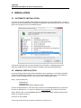
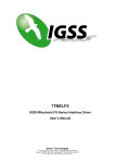
7TMELSQ IGSS Mitsubishi Melsec Q Series Interface Driver User’s Manual Seven Technologies 7-Technologies A/S * Bistruphave 3 * DK-3460 Birkerød * Denmark Phone: +45 45 900 700 * Fax: +45 45 900 701 * CVR no. DK 73 63 41 13 E-mail: [email protected] World Wide Web: http://www.7t.dk 7TMELSQ IGSS Mitsubishi Melsec Q Series Interface driver DISCLAIMER : This is an unpublished work, the copyright of which vests in SEVEN TECHNOLOGIES A/S. All rights reserved. The information contained herein is the property of SEVEN TECHNOLOGIES and is supplied without liability for errors or omissions. No part may be reproduced or used except as authorised by contract or other written permission. The copyright and the foregoing restriction on reproduction and use extend to all media in which the information may be embodied. D:\DEV\IGSS32V9\DEV\DOC\HELP\DRIVER DOCUMENTATION\7TMELSQ.DOC 7TMELSQ IGSS Mitsubishi Melsec Q Series Interface driver CONTENTS: 1 2 3 4 5 6 INTRODUCTION................................................................................................................. 3 1.1 Software Requirements .......................................................................................... 3 1.2 Hardware Requirements ........................................................................................ 3 INSTALLATION ................................................................................................................... 4 2.1 Automatic Installation ............................................................................................. 4 2.2 Manual Installation.................................................................................................. 4 CONFIGURING THE DRIVER ............................................................................................ 5 CONFIGURING THE OBJECTS ....................................................................................... 10 4.1 Supported Memory Types .................................................................................... 11 PERFORMANCE AND THROUGHPUT ........................................................................... 13 ERROR CODES................................................................................................................ 14 D:\DEV\IGSS32V9\DEV\DOC\HELP\DRIVER DOCUMENTATION\7TMELSQ.DOC 7TMELSQ IGSS Mitsubishi Melsec Q Series Interface driver 1 INTRODUCTION This document describes how to set up and troubleshoot the IGSS 7TMELSQ Interface Driver. The driver implements the Mitsubishi Melsec Q FORMAT 5 protocol stack. 1.1 SOFTWARE REQUIREMENTS None (see Hardware Requirements below). The driver is designed to be used with IGSS version 8.0 and higher. 1.2 HARDWARE REQUIREMENTS The driver requires one or more RS232 serial interfaces. The Mitsubishi Q Series PLC’s have a number of available interface modules (e.g. the QJ71C24N-R1 or QJ71C24N-R2) for serial communication. At least one serial port is required to be available on the PLC. Please refer to Mitsubishi documentation for cable, setup and wiring instructions. D:\DEV\IGSS32V9\DEV\DOC\HELP\DRIVER DOCUMENTATION\7TMELSQ.DOC 7TMELSQ IGSS Mitsubishi Melsec Q Series Interface driver 2 INSTALLATION 2.1 AUTOMATIC INSTALLATION The driver is normally installed automatically along with the rest of the IGSS system. To verify if the driver has been installed open the System Configuration (sysconfig.exe) and check if a driver with ID:79 is present in the list of available drivers: If the driver is present then you can proceed to the next section: “Configuring the Driver”, otherwise install the driver using the manual installation procedure described below. 2.2 MANUAL INSTALLATION Using the following step-by-step guide will install the driver manually on a PC where the IGSS system has already been installed. You need to stop the IGSS system prior to the installation and you need to be logged in with a user account with “Administrator” rights. Step 1: Verify that the files: 7TMELSQ.DLL 7TMELSQc.DLL COMMDRV.REG (latest updated version) exists in the GSS\ directory. If the files doesn’t exists run the IGSSUpdateClient to get the files from the 7T WEB server – or contact 7T Support ([email protected]) to get the files via e-mail. Step 2: Double-click on the COMMDRV.REG file to import the registry settings needed for the system to recognize the driver. The driver is now installed. D:\DEV\IGSS32V9\DEV\DOC\HELP\DRIVER DOCUMENTATION\7TMELSQ.DOC 7TMELSQ IGSS Mitsubishi Melsec Q Series Interface driver 3 CONFIGURING THE DRIVER This section describes how to configure the driver parameters. All parameters must be configured by using the System Configuration (sysconfig.exe) application. Please note that the IGSS system MUST be stopped and restarted for the configured parameters to take effect. Start the System Configuration application and add the driver 7TMELSQ (ID:79) to the requested station. Once the driver has been added to the relevant station then you are ready to proceed with adding PLC nodes. This is done by right-clicking on the driver and select “New Interface” menu point. D:\DEV\IGSS32V9\DEV\DOC\HELP\DRIVER DOCUMENTATION\7TMELSQ.DOC 7TMELSQ IGSS Mitsubishi Melsec Q Series Interface driver On the “Connection Type” you specify the type of connection: Direct connection Modem Connection Other connection (e.g. Radio Connection) The Mitsubishi Melsec Q interface driver is designed for “Direct Connection”, so you should select the “Connect directly via the serial port” option. D:\DEV\IGSS32V9\DEV\DOC\HELP\DRIVER DOCUMENTATION\7TMELSQ.DOC 7TMELSQ IGSS Mitsubishi Melsec Q Series Interface driver Switch to the “Serial Port” pane: Since the Mitsubishi Melsec Q protocol is designed for point-to-point communication you need one serial port for each PLC you connect to. The IGSS Mitsubishi Melsec Q driver supports up to 8 serial ports (8 PLC connections). Each port must be configured with Serial port ID (e.g. \\.\COM1:) and serial port parameters. Default serial parameters are 9600 Baud, 8 data bits, 1 stop bit and odd parity. These parameters are also default for the communication port of the Mitsubishi Melsec Q series PLCs. D:\DEV\IGSS32V9\DEV\DOC\HELP\DRIVER DOCUMENTATION\7TMELSQ.DOC 7TMELSQ IGSS Mitsubishi Melsec Q Series Interface driver Add a node by right clicking the channel in the left side tree-view and select the “New Node” menu when the pop-up appears: Each PLC node requires a few fundamental parameters: IGSS node number: This is the node number which IGSS uses to reference a unique PLC. This node number is required when binding and IGSS atom (tag) to a register in the PLC. Any number from the drop down list can be used. Station number: The station number designates the number set on the Q series C24 module. This number is normally 0 (zero) but can be set using the GX Developer software from Mitsubishi. If you have more Mitsubishi Melsec Q stations in a multi-drop configuration each station must be designated with a separate unique station number. PC number: The PC number is only used when routing is required. The driver currently doesn’t support routing and thus the PC number should always be set to 255 (default). If your application requires routing please contact 7T technical support for guidelines. Use Block Check Code: This option is use to set if the driver should expect and check a Block Check Code (BCC) at the end of each telegram. Normally this option should be checked (BCC enabled) but if you are using the programming port on the PLC (instead of a communication D:\DEV\IGSS32V9\DEV\DOC\HELP\DRIVER DOCUMENTATION\7TMELSQ.DOC 7TMELSQ IGSS Mitsubishi Melsec Q Series Interface driver board) then you should uncheck this option and thus instruct the driver to disregard BCC. Telegram retries: Here you can specify the number of telegram reties the driver should use before issuing a communication fault. The default value is 3 which suit most applications. If you experience frequent communication faults you might try to increase this parameter. D:\DEV\IGSS32V9\DEV\DOC\HELP\DRIVER DOCUMENTATION\7TMELSQ.DOC 7TMELSQ IGSS Mitsubishi Melsec Q Series Interface driver 4 CONFIGURING THE OBJECTS Once the driver and the PLC nodes have been defined, IGSS Objects and Atoms can be linked to process variable in the PLC. Various different types of PLC memory can be accessed for read/write operations using the driver. By using the “Edit Mapping” tab in the object properties dialog you can specify the binding between the object’s atoms and the PLC process variables. Start by selecting an atom and select the 7TMELSQ driver in the “Driver” drop down list: Now select the desired PLC node number and continue by setting be desired Device. Then specify the number (register number within the device type). Note that the corresponding Mnemonic is displayed and updated as you select the appropriate parameters. This is a help to make sure you always bind to the correct process variable. Continue this process for each atom on the object and save the parameters by clicking the OK D:\DEV\IGSS32V9\DEV\DOC\HELP\DRIVER DOCUMENTATION\7TMELSQ.DOC 7TMELSQ IGSS Mitsubishi Melsec Q Series Interface driver button when finished. 4.1 SUPPORTED MEMORY TYPES The driver supports a number of different device types in the PLC: 16-Bit types: Device type Data Register Spec. Data Register Link Register Spec. Link Register File Register Index Register Timer Value Counter Value Retentive Timer Value Valid Range Q02(H), Q06, Q12H, Q00J, Q00, Q01 Q25, Q12PH, Q25PH, Q2A, Q2A-S1, Q2AS, Q2AS-S1, Q2ASH, Q2ASH – S1, Q3A, Q4A, Q4AR D00000-D12287 D00000-D11135 DS00000-DS02047 DS00000-DS01023 W0000-W1FFF (hex) W0000-W07FF (hex) SW0000-SW07FF (hex) SW0000-SW03FF (hex) R00000-R32767 R00000-R32767 Z00-Z15 Z0-Z9 TN000-TN2047 TN000-TN0511 CN000-CN2047 CN000-CN0511 SN000-SN2047 SN000-SN0511 Read/Write Valid Range Q02(H), Q06, Q12H, Q00J, Q00, Q01 Q25, Q12PH, Q25PH, Q2A, Q2A-S1, Q2AS, Q2AS-S1, Q2ASH, Q2ASH – S1, Q3A, Q4A, Q4AR X0000-X1FFF (hex) X0000-X07FF (hex) DX0000-DX1FFF (hex) DX0000-DX07FF (hex) Y0000-Y1FFF (hex) Y0000-Y07FF (hex) DY0000-DY1FFF (hex) DY0000-DY07FF (hex) M00000-M08191 M00000-M08191 L00000-L08191 L00000-L02047 F00000-F02047 F00000-F01023 V00000-V02047 V00000-V01023 B0000-B1FFF (hex) B0000-B07FF (hex) TS000-TS2047 TS000-TS0511 TC000-TC2047 TC000-TC0511 CS000-CS2047 CS000-CS0511 CC000-CC2047 CC000-CC0511 SS000-SS2047 SS000-SS0511 Read/Write R/W R/W R/W R/W R/W R/W R/W R/W R/W 1-Bit (Boolean) types: Device type Input Relay Direct Input Output Relay Direct Output Internal Relay Latch Relay Annunciator Edge Relay Link Relay Timer Contact Timer Coil Counter Contact Counter Coil Retentive Timer Contact Retentive Timer Coil Spec. Link Relay Step Relay SC000-SC2047 SB0000-SB07FF (hex) S00000-S08191 SC000-SC0511 SB0000-SB03FF (hex) S00000-S02047 These addressing methods allow you to bind to any type of process value in the PLC. D:\DEV\IGSS32V9\DEV\DOC\HELP\DRIVER DOCUMENTATION\7TMELSQ.DOC R R R/W R/W R/W R/W R/W R/W R/W R/W R/W R/W R/W R/W R/W R/W R/W 7TMELSQ IGSS Mitsubishi Melsec Q Series Interface driver Please note that if you want to bind to a 32 bit (DWORD) value then use word addressing and specify the external type as one of the supported 32 bit types, then the system will automatically do the correct addressing. If you e.g. want to bind to a floating point process value at D0254 you should specify: D0254 and select the external type FLOAT. Then the Driver will automatically fetch both D0254 and D0255 and interpret the content as a floating point (IEEE float) value. Please note that all bit types (Input Relay, Output Relay etc.) are *only* one bit values when written as a command to the PLC. I.e. if you bind a digital command to Y012 and send the command “->1” then *only* Output Relay 012 is written. This means that you can’t send complex commands that require more than one bit to be set/reset. The driver automatically fetches at least 16 bits when a specific bit is referenced. If you e.g. define a digital object which mimics the state of 3 Relays combined (e.g. Y005, Y007 and Y013) then the driver automatically fetches the range Y000 -> Y015 to ensure that all bits are read from the PLC. IT IS HIGHLY RECOMMENTED to use Data Register as the primary memory type for exchanging variable information between IGSS and the PLC. Read- and especially write operations directly to Output, Timers and Counters cannot be verified by the PLC program and might thus lead to hazards. D:\DEV\IGSS32V9\DEV\DOC\HELP\DRIVER DOCUMENTATION\7TMELSQ.DOC 7TMELSQ IGSS Mitsubishi Melsec Q Series Interface driver 5 PERFORMANCE AND THROUGHPUT The driver is designed for maximum throughput on any given serial link. On a standard PC with a 9600 baud serial port (or comparable) you should expect a throughput of 8+ request/response cycles pr. second. Each PLC node is handled concurrent and independently. This means that if you add more PLC’s to the system then the throughput pr. PLC should only be affected marginally provided that the PC throughput is sufficient. IMPORTANT NOTICE: The IGSS communication engine optimizes communication throughput by seeking to group data whenever possible. This means that if the communication engine is required to read e.g. D0001 and D0031 then it will read data registers D0001, D0002, … , D0031 as a block. This is much more efficient than reading the two data registers using two separate read requests. D:\DEV\IGSS32V9\DEV\DOC\HELP\DRIVER DOCUMENTATION\7TMELSQ.DOC 7TMELSQ IGSS Mitsubishi Melsec Q Series Interface driver 6 ERROR CODES This section describes the error codes specific to the IGSS 7TMELSQ interface driver. While troubleshooting communication- or addressing problems the Driver Test Application might be useful to display error codes reported by the driver. 0x4F01: _7TMELSQ_NODEINFO_MISSING Cause: The driver failed to look up information (Station number, Network number etc.) for a specific PLC node. Action: Check that all nodes are properly defined and that all nodes are configured on the correct channels (e.g. COM1:). Subcode contains the node number which do not have any proper node information. 0x4F02: _7TMELSQ_RESP_TOO_SHORT Cause: The driver received a response telegram from a PLC which is too short to be a valid telegram. Action: Please check hardware and cables. Check baudrate, data bits, parity etc. These should normally be 9600,ODD,8,1 or 19200,ODD,8,1. Hardware flow control might be needed depending on cabels and converters. Check that all ground signals are wired correctly. Subcode contains the actual length of the telegram 0x4F03: _7TMELSQ_INVALID_DATA_REGISTER_TYPE Cause: The driver was requested to read or write an unsupported data type. Action: Check that all configured addresses are valid. Use the driver test application (T7T) to identify the data block code for the offending request. 0x4F04: _7TMELSQ_INVALID_MESSAGE_TYPE Cause: The driver was requested to read or write an unsupported message type type. Action: Contact 7T support. 0x4F05: _7TMELSQ_IO_WRITE_ERROR_LEN Cause: The driver is unable to write data to the serial port. Action: Please check hardware and cables. 0x4F06: _7TMELSQ_IO_READ_TIMEOUT Cause: The driver is unable to receive any data on the serial link. Action: Please check hardware and cables. Check baud rate, data bits, parity etc. These should normally be 9600,ODD,8,1 or 19200,ODD,8,1. Hardware flow control might be needed depending on cables and converters. 0x4F07: _7TMELSQ_COM_READ_ERROR Cause: An error has occured while reading from the serial (COM) port. Action: Please check hardware and cables. Check baud rate, data bits, parity etc. These should normally be 9600,ODD,8,1 or 19200,ODD,8,1. Hardware flow control might be needed depending on cables and converters. Check that all ground signals are wired correctly. Subcode contains the actual error code from Windows serial driver. 0x4F08: _7TMELSQ_IO_BCC_ERROR Cause: Driver received a telegram with an incorrect block check code D:\DEV\IGSS32V9\DEV\DOC\HELP\DRIVER DOCUMENTATION\7TMELSQ.DOC 7TMELSQ IGSS Mitsubishi Melsec Q Series Interface driver Action: Please check hardware and cables. Check baud rate, data bits, parity etc. These should normally be 9600,ODD,8,1 or 19200,ODD,8,1. Hardware flow control might be needed depending on cables and converters. Check that all ground signals are wired correctly. 0x4F09: _7TMELSQ_IO_INCORRECT_FRAMING Cause: Driver received a telegram with an incorrect block check code Action: Please check hardware and cables. Check baud rate, data bits, parity etc. These should normally be 9600,ODD,8,1 or 19200,ODD,8,1. Hardware flow control might be needed depending on cables and converters. Check that all ground signals are wired correctly. 0x4F0A: _7TMELSQ_TOO_FEW_RESP_DATA Cause: The driver received a response telegram from a PLC which has too few actual data compared to the expected amount of data. Action: Please check hardware and cables. Check baud rate, data bits, parity etc. These should normally be 9600,ODD,8,1 or 19200,ODD,8,1. Hardware flow control might be needed depending on cables and converters. Check that all ground signals are wired correctly. Subcode contains the actual length of the telegram. 0x4F0B: _7TMELSQ_UNEXP_RESP_HEADER Cause: The driver received a response telegram from a PLC which had an unexpected header. Action: Please check hardware and cables. Check baud rate, data bits, parity etc. These should normally be 9600,ODD,8,1 or 19200,ODD,8,1. Hardware flow control might be needed depending on cables and converters. Check that all ground signals are wired correctly. 0x4F0C: _7TMELSQ_PLC_ERROR_RESP Cause: The driver received a response telegram from a PLC with an error code Action: Please check that all addresses are correct and valid. Check that all cables and communication modules are OK. Subcode contains the error code received from the PLC. Please check the Mitsubishi documentation for exact interpretation. #0x4F0D: _7TMELSQ_DATA_BLOCK_TOO_BIG Cause: The driver was requested to read/write a block bigger than 32 data words. Action: Check that driver segment length is less or equal to 32 data words. D:\DEV\IGSS32V9\DEV\DOC\HELP\DRIVER DOCUMENTATION\7TMELSQ.DOC