1
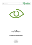
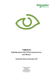
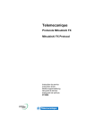
7TMELFX IGSS Mitsubishi FX-Series Interface Driver User’s Manual Seven Technologies 7-Technologies A/S * Bistruphave 3 * DK-3460 Birkerød * Denmark Phone: +45 45 900 700 * Fax: +45 45 900 701 * CVR no. DK 73 63 41 13 E-mail: [email protected] World Wide Web: http://www.7t.dk 7TMELFX IGSS Mitsubishi FX Interface driver DISCLAIMER : This is an unpublished work, the copyright of which vests in SEVEN TECHNOLOGIES A/S. All rights reserved. The information contained herein is the property of SEVEN TECHNOLOGIES and is supplied without liability for errors or omissions. No part may be reproduced or used except as authorised by contract or other written permission. The copyright and the foregoing restriction on reproduction and use extend to all media in which the information may be embodied. D:\DEV\IGSS_80\HELP - FLARE PROJEKTER\DRIVER DOCUMENTATION\7TMELFX.DOC/2000-0314/AUTHOR/SECRETARY 7TMELFX IGSS Mitsubishi FX Interface driver CONTENTS: 1 2 3 4 5 6 INTRODUCTION................................................................................................................. 3 1.1 Software Requirements .......................................................................................... 3 1.2 Hardware Requirements ........................................................................................ 3 INSTALLATION ................................................................................................................... 4 2.1 Automatic Installation ............................................................................................. 4 2.2 Manual Installation.................................................................................................. 4 CONFIGURING THE DRIVER ............................................................................................ 5 CONFIGURING THE OBJECTS ......................................................................................... 9 4.1 Supported Memory Types .................................................................................... 10 PERFORMANCE AND THROUGHPUT ........................................................................... 11 ERROR CODES................................................................................................................ 12 D:\DEV\IGSS_80\HELP - FLARE PROJEKTER\DRIVER DOCUMENTATION\7TMELFX.DOC/2000-0314/AUTHOR/SECRETARY 7TMELFX IGSS Mitsubishi FX Interface driver 1 INTRODUCTION This document describes how to set up and troubleshoot the IGSS 7TMELFX Interface Driver. 1.1 SOFTWARE REQUIREMENTS None (see Hardware Requirements below). The driver is designed to be used with IGSS version 6.0 and higher. 1.2 HARDWARE REQUIREMENTS The driver requires a RS422 interface (or applicable converter RS422/USB, RS422/RS232, RS422/Ethernet) to be installed on the PC. If converters are used then the interface provided by the converter must install a virtual serial driver (\\.\COMx:). The Mitsubishi FX Series programming port is equipped with an 8 pin Mini-Din connector. The diagram blew can be used to manufacture a cable connecting the 8 pin Mini-Din to a RS232/RS422 (USB/RS422 or Ethernet/RS422) converter. D:\DEV\IGSS_80\HELP - FLARE PROJEKTER\DRIVER DOCUMENTATION\7TMELFX.DOC/2000-0314/AUTHOR/SECRETARY 7TMELFX IGSS Mitsubishi FX Interface driver 2 INSTALLATION 2.1 AUTOMATIC INSTALLATION The driver is normally installed automatically along with the rest of the IGSS system. To verify if the driver has been installed open the System Configuration (sysconfig.exe) and check if a driver with ID:82 is present in the list of available drivers: If the driver is present then you can proceed to the next section: “Configuring the Driver”, otherwise install the driver using the manual installation procedure described below. 2.2 MANUAL INSTALLATION Using the following step-by-step guide will install the driver manually on a PC where the IGSS system has already been installed. You need to stop the IGSS system prior to the installation and you need to be logged in with a user account with “Administrator” rights. Step 1: Verify that the files: 7TMELFX.DLL 7TMELFXc.DLL COMMDRV.REG (latest updated version) exists in the GSS\ directory. If the files doesn’t exists run the IGSSUpdateClient to get the files from the 7T WEB server – or contact 7T Support ([email protected]) to get the files via e-mail. Step 2: Double-click on the COMMDRV.REG file to import the registry settings needed for the system to recognize the driver. The driver is now installed. D:\DEV\IGSS_80\HELP - FLARE PROJEKTER\DRIVER DOCUMENTATION\7TMELFX.DOC/2000-0314/AUTHOR/SECRETARY 7TMELFX IGSS Mitsubishi FX Interface driver 3 CONFIGURING THE DRIVER This section describes how to configure the driver parameters. All parameters must be configured by using the System Configuration (sysconfig.exe) application. Please note that the IGSS system MUST be stopped and restarted for the configured parameters to take effect. Start the System Configuration application and add the driver 7TMELFX (ID:82) to the requested station. Once the driver has been added to the relevant station then you are ready to proceed with adding PLC nodes. This is done by right-clicking on the driver and select “New Interface” menu point. D:\DEV\IGSS_80\HELP - FLARE PROJEKTER\DRIVER DOCUMENTATION\7TMELFX.DOC/2000-0314/AUTHOR/SECRETARY 7TMELFX IGSS Mitsubishi FX Interface driver On the “Connection Type” you specify the type of connection: Direct connection Modem Connection Other connection (e.g. Radio Connection) The Mitsubishi FX interface driver is designed for “Direct Connection”, so you should select the “Connect directly via the serial port” option. D:\DEV\IGSS_80\HELP - FLARE PROJEKTER\DRIVER DOCUMENTATION\7TMELFX.DOC/2000-0314/AUTHOR/SECRETARY 7TMELFX IGSS Mitsubishi FX Interface driver Switch to the “Serial Port” pane: Since the Mitsubishi FX protocol is designed for point-to-point communication you need one serial port for each PLC you connect to. The IGSS Mitsubishi FX driver supports up to 8 serial ports (8 PLC connections). Each port must be configured with Serial port ID (e.g. \\.\COM3:) and serial port parameters. Default serial parameters are 9600 Baud, 7 data bits, 1 stop bit and even parity. These parameters are also default for the programming port of the Mitsubishi FX series PLCs. D:\DEV\IGSS_80\HELP - FLARE PROJEKTER\DRIVER DOCUMENTATION\7TMELFX.DOC/2000-0314/AUTHOR/SECRETARY 7TMELFX IGSS Mitsubishi FX Interface driver Add a node by right clicking the channel in the left side tree-view and select the “New Node” menu when the pop-up appears: Each PLC node requires a few fundamental parameters: IGSS node number: This is the node number which IGSS uses to reference a unique PLC. This node number is required when binding and IGSS atom (tag) to a register in the PLC. Any number from the drop down list can be used. Device Type: Here you must select the device type which matches your PLC equipment best. Device types: FX, FX0 and FX0N use the simple FX protocol type. Device types: FX2N and FX3U use the extended FX protocol type. Telegram retries: Here you can specify the number of telegram reties the driver should use before issuing a communication fault. The default value is 3 which suit most applications. If you experience frequent communication faults you might try to increase this parameter. D:\DEV\IGSS_80\HELP - FLARE PROJEKTER\DRIVER DOCUMENTATION\7TMELFX.DOC/2000-0314/AUTHOR/SECRETARY 7TMELFX IGSS Mitsubishi FX Interface driver 4 CONFIGURING THE OBJECTS Once the driver and the PLC nodes have been defined, IGSS Objects and Atoms can be linked to process variable in the PLC. Various different types of PLC memory can be accessed for read/write operations using the driver. By using the “Edit Mapping” tab in the object properties dialog you can specify the binding between the object’s atoms and the PLC process variables. Start by selecting an atom and select the 7TMELFX driver in the “Driver” drop down list: Now select the desired PLC node number and continue by setting be desired Device. Then specify the number (register number within the device type). Note that the corresponding Mnemonic is displayed and updated as you select the appropriate parameters. This is a help to make sure you always bind to the correct process variable. Continue this process for each atom on the object and save the parameters by clicking the OK D:\DEV\IGSS_80\HELP - FLARE PROJEKTER\DRIVER DOCUMENTATION\7TMELFX.DOC/2000-0314/AUTHOR/SECRETARY 7TMELFX IGSS Mitsubishi FX Interface driver button when finished. 4.1 SUPPORTED MEMORY TYPES The driver supports a number of different device types in the PLC: 16-Bit types: Device type Data Register Spec. Data Register Timer Value Counter Value Valid Range FX, FX0 and FX0N FX2N and FX3U D0000-D0999 D0000-D7999 D8000-D8255 D8000-D8511 T000-T255 T000-T511 C000-C199 C000-C199 Read/Write Valid Range FX, FX0 and FX0N FX2N and FX3U M0000-M1535 M0000-M7679 M8000-M8255 M8000-M8511 X000-X377 (octal) X000-X377 (octal) Y000-Y377 (octal) Y000-Y377 (octal) S000-S999 S0000-S4095 Read/Write R/W R/W R/W R/W 1-Bit (Boolean) types: Device type Aux Relays Spec. Aux Relays Input Output State R/W R/W R R/W R/W These addressing methods allow you to bind to any type of process value in the PLC. Please note that if you want to bind to a 32 bit (DWORD) value then use word addressing and specify the external type as one of the supported 32 bit types, then the system will automatically do the correct addressing. If you e.g. want to bind to a floating point process value at D0254 you should specify: D0254 and select the external type FLOAT. Then the Driver will automatically fetch both D0254 and D0255 and interpret the content as a floating point (IEEE float) value. Please note that all bit types (Aux Relay, Inputs, Outputs and States) are *only* one bit values when written as a command to the PLC. I.e. if you bind a digital command to M0123 and send the command “->1” then *only* Aux Relay M0123 is written. This means that you can’t send complex commands that require more than one bit to be set/reset. The driver automatically fetches at least 16 bits when a specific bit is referenced. If you e.g. define a digital object which mimics the state of 3 Relays combined (e.g. M0111, M112 and M113) then the driver automatically fetches the range M0111 -> M0126 to ensure that all bits are read from the PLC. IT IS HIGHLY RECOMMENTED to use Data Register and Aux. Relays as the primary memory type for exchanging variable information between IGSS and the PLC. Read- and especially write operations directly to Output, Timers and Counters cannot be verified by the PLC program and might thus lead to hazards. D:\DEV\IGSS_80\HELP - FLARE PROJEKTER\DRIVER DOCUMENTATION\7TMELFX.DOC/2000-0314/AUTHOR/SECRETARY 7TMELFX IGSS Mitsubishi FX Interface driver 5 PERFORMANCE AND THROUGHPUT The driver is designed for maximum throughput on any given serial link. On a standard PC with a 9600 baud serial port (or comparable) 100 connection to the PLC you should expect a throughput of 6+ request/response cycles pr. second. Each PLC node is handled concurrent and independently. This means that if you add more PLC’s to the system then the throughput pr. PLC should only be affected marginally provided that the PC throughput is sufficient. IMPORTANT NOTICE: The IGSS communication engine optimizes communication throughput by seeking to group data whenever possible. This means that if the communication engine is required to read e.g. D0001 and D0031 then it will read data registers D0001, D0002, … , D0031 as a block. This is much more efficient than reading the two data registers using two separate read requests. D:\DEV\IGSS_80\HELP - FLARE PROJEKTER\DRIVER DOCUMENTATION\7TMELFX.DOC/2000-0314/AUTHOR/SECRETARY 7TMELFX IGSS Mitsubishi FX Interface driver 6 ERROR CODES This section describes the error codes specific to the IGSS 7TMELFX interface driver. While troubleshooting communication- or addressing problems the Driver Test Application might be useful to display error codes reported by the driver. 0x5201: 7TMITFX_ADDRESS_OUT_OF_RANGE Cause: The address specified is out of range for this PLC type Action: Check that addresses are within valid range. See valid ranges above. 0x5202: 7TMITFX_WRITE_BLOCK_TOO_BIG Cause: The driver was requested to write a block bigger than 32 data words Action: Check that driver segment length is less or equal to 32 data words 0x5203: 7TMITFX_INVALID_DATA_REGISTER_TYPE Cause: The driver was requested to read or write an unsupported data type. Action: Check that all configured addresses are valid. 0x5204: 7TMITFX_INVALID_MESSAGE_TYPE Cause: The driver was requested to read or write an unsupported message type type. Action: Contact 7T support. 0x5205: 7TMITFX_IO_WRITE_ERROR_LEN Cause: The driver is unable to write data to the serial port. Action: Please check hardware and cables. 0x5206: 7TMITFX_IO_READ_TIMEOUT Cause: The driver is unable to receive any data on the serial link. Action: Please check hardware and cables. Check baud rate, data bits, parity etc. These should normally be 9600,EVEN,7,1. Hardware flow control might be needed depending on cables and converters. 0x5207: 7TMITFX_COM_READ_ERROR Cause: An error occurred while reading from the serial (COM) port. Action: Please check hardware and cables. Check baud rate, data bits, parity etc. These should normally be 9600,EVEN,7,1. Hardware flow control might be needed depending on cables and converters. Check that all ground signals are wired correct Sub code contains the actual error code from Windows serial driver. 0x5208: 7TMITFX_IO_BCC_ERROR Cause: Driver received a telegram with an incorrect block check code Action: Please check hardware and cables. Check baud rate, data bits, parity etc. These should normally be 9600,EVEN,7,1. Hardware flow control might be needed depending on cables and converters. Check that all ground signals are wired correctly 0x5209: 7TMITFX_IO_INCORRECT_FRAMING Cause: Driver received a telegram with an incorrect block check code Action: Please check hardware and cables. Check baud rate, data bits, parity etc. These should normally be 9600,EVEN,7,1. Hardware flow control might be needed depending on cables and converters. Check that all ground signals are wired correctly D:\DEV\IGSS_80\HELP - FLARE PROJEKTER\DRIVER DOCUMENTATION\7TMELFX.DOC/2000-0314/AUTHOR/SECRETARY 7TMELFX IGSS Mitsubishi FX Interface driver 0x520A: 7TMITFX_IO_NAK_RECEIVED Cause: Driver received a telegram with a NAK (Not Acknowledge) Action: This is typically caused by sending commands to address areas with dosn’t allow writing. 0x520B: 7TMITFX_INPUT_FLAGS_NOT_WRITEABLE Cause: Driver received a message requesting to write to input flags. This is not allowed. Action: Fix application so no commands can be written to input flags. 0x520C: 7TMITFX_READ_BLOCK_TOO_BIG Cause: The driver was requested to read a block bigger than 32 data words Action: Check that driver segment length is less or equal to 32 data words D:\DEV\IGSS_80\HELP - FLARE PROJEKTER\DRIVER DOCUMENTATION\7TMELFX.DOC/2000-0314/AUTHOR/SECRETARY