1
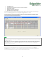
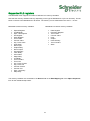
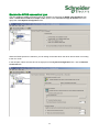
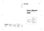
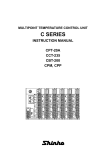
7TMITETH IGSS Mitsubishi FX/Q TCP/IP Interface Driver User Manual Schneider Electric Denmark A/S Schneider Electric IGSS-Automation Bistruphave 3 DK-3460 Birkerød, Denmark Phone: +45 45 900 700 www.schneider-electric.com VAT no. DK 73 63 41 13 Disclaimer The information provided in this documentation contains general descriptions and/or technical characteristics of the performance of the products contained therein. The documentation is not intended as a substitute for and is not to be used for determining suitability or reliability of these products for specific user applications. It is the duty of any such user or integrator to perform the appropriate and complete risk analysis, evaluation and testing of the products with respect to the relevant specific application of use thereof. Neither Schneider Electric nor any of its affiliates or subsidiaries shall be responsible or liable for misuse of the information contained herein. The information contained herein is the property of Schneider electric and is supplied without liability for errors or omissions. If you have any suggestions for improvements or amendments or have found errors in this publication, please notify us. No part of this document may be reproduced in any form or by any means, electronic or mechanical, including photocopying, without express written permission of Schneider Electric. All pertinent state, regional and local safety regulations must be observed when installing and using this product. For reasons of safety and to help ensure compliance with documented system data, only the manufacturer should perform repairs to components. Failure to use Schneider Electric software or approved software with our hardware products may result in injury, harm or improper operating results. Failure to observe this information can result in injury or equipment damage. ©2004, 2014, Schneider Electric, All rights reserved. Schneider Electric 7-Technologies A/S Bistruphave 3 DK-3460 Birkerød, Denmark Phone: +45 45 900 700 www.schneider-electric.com VAT no. DK 73 63 41 13 2 Contents Disclaimer .......................................................................................................................................................... 2 Introduction ........................................................................................................................................................ 4 Driver Files .............................................................................................................................................. 4 Software Requirements ........................................................................................................................... 4 Hardware Requirements ......................................................................................................................... 5 Installation .......................................................................................................................................................... 5 Automatic Installation .............................................................................................................................. 5 Manual Installation................................................................................................................................... 6 Driver Configuration ........................................................................................................................................... 7 Configuring the driver .............................................................................................................................. 7 Adding new PLC machines ..................................................................................................................... 8 Node Parameters .................................................................................................................................. 10 Testing the connection .......................................................................................................................... 11 Mitsubishi Installation ....................................................................................................................................... 11 PLC Setup ............................................................................................................................................. 11 Object Configuration ........................................................................................................................................ 14 Supported PLC registers ....................................................................................................................... 15 Use with GPRS Networks ................................................................................................................................ 16 Enable the GPRS connection type ........................................................................................................ 17 Performance and Throughput .......................................................................................................................... 18 Schneider Electric IGSS-Automation Bistruphave 3 DK-3460 Birkerød, Denmark Phone: +45 45 900 700 www.schneider-electric.com VAT no. DK 73 63 41 13 Introduction This document describes how to set up and troubleshoot the IGSS 7TMITETH Interface Driver. The IGSS program must be installed as an IGSS Server on the machine which is to be the IGSS Server and a functioning network of personal computers and PLCS must be in place prior to installing and configuring the driver. Driver Files The following files are used set up and troubleshoot the IGSS 7TMITETH driver: 7TMITETH.DLL: Contains the protocol stack required for communication with Mitsubishi FX and Q PLCs using ethernet TCP/IP interfaces. 7TMITETHc.DLL: Contains the graphical user interface used to configure the 7TMITETH driver. Driver89.reg: Contains the required information which must be correctly updated in the Windows registry in order for the IGSS program to make use of the driver. The files are usually located in the GSS folder of the IGSS installation. Default IGSS installation folder: The default IGSS installation folder is: For 32-bit machines: C:\Program Files\Schneider Electric\IGSS32\<IGSS Version> For 64-bit machines: C:\Program Files (x86)\Schneider Electric\IGSS32\<IGSS Version> If you have installed IGSS Version 11, the <IGSS Version> folder name will be V11.0. Software Requirements The 7TMITETH driver is designed to be used with IGSS version 10 or higher. The 7TMITETH driver uses the standard Microsoft TCP/IP protocol stack. The protocol is normally installed in all Microsoft operating systems and can be used as it is. DNS and other support protocols are not used by the driver and do not need to be installed or configured. The 7TMITETH driver uses the ISO transport layer on top of the TCP/IP protocol as it is defined in the RFC. This means the TCP/IP port must be accessible and opened for use. If you are employing a firewall, please be aware that the port used for TCP/IP communication must be open for bi-directional connections. If the network addresses from the IGSS program to the PLC machines include more firewall, all of these must be configured correctly to allow bi-directional TCP/IP communication. 4 Hardware Requirements The 7TMITETH driver requires a standard Ethernet Network Interface Controller (NIC) interface with TCP/IP (UDP/IP) installed in the PC which contains the IGSS program. The IGSS Mitsubishi Ethernet driver can connect with Mitsubishi PLC machines, Q-series or FX3-series. An Ethernet port supporting TCP/IP (UDP/IP) is required on the Mitsubishi PLC’s. Please refer to Mitsubishi documentation for cable, setup and wiring instructions. Installation The IGSS 7TMITETH Interface Driver is assigned the Driver ID 89 in the IGSS program and can be seen and selected in the System Configuration form when setting up the IGSS configuration. Once the IGSS program has been installed on the IGSS Server machine and the IGSS Master has been started, the configuration which is to use the 7TMITETH driver can be opened in the IGSS Master and set up in the System Configuration form. Automatic Installation The driver is normally installed when IGSS is installed. To verify that the driver has been installed correctly, open the System Configuration form. In the left pane of the System Configuration form, select an IGSS station and click Edit > New Driver.(or right-click the station and select New Driver) The 7TMITETH driver (Driver 89) should be found in the list of available drivers in the Select Communication Driver form. 5 If the 7TMITETH driver is present in the Select Communication Driver form, you can proceed to the Driver Configuration chapter. If the 7TMITETH driver is not present in the Select Communication Driver form, you must install the driver manually. (See Manual Installation below) Manual Installation You can manually install the 7TMITETH driver if it is not present in the IGSS installation by following the process described below. You must stop the IGSS configuration in order to install the driver and you must have Local Administrator rights on the local machine in order to make the necessary changes to the machine registry as well as update files in the Program Files folders, if that is where IGSS has been installed. To manually install the 7TMITETH driver 1. Copy the following files to the IGSS installation folder: a. 7TMITETH.dll b. 7TMITETHc.dll c. 7TMITETH.reg 2. Locate the 7TMITETH.reg file and double-click the file to update the windows registry settings. You can also open the Windows Registry Editor and import the file from the Windows Registry Editor. 6 Driver Configuration This section describes how to configure the driver parameters All driver parameters and set up options are configured in the System Configuration form. The System Configuration form is opened by clicking the System Configuration button in the IGSS Master > Design and Setup tab. Note The IGSS configuration must be stopped and restarted for the configured driver parameters to take effect. Configuring the driver Once the driver has been added to the station, you can configure the driver, creating and setting up the interface and nodes of the 7TMITETH driver. In the left pane of the System Configuration form, select the station (IGSS server or Operator Station with/Distributed Driver) and expand the driver list under the station. Select the Mitsubishi Q/FX Series driver. If the Mitsubishi Q/FX Series driver is not present, add the driver by right-clicking the station and selecting New Driver. In the Select Communication Driver form, select the 7TMITETH Mitsubishi Ethernet TCP/IP driver (Driver ID: 89). 7 Adding new PLC machines When a new PLC machine is added, you can add a new node representing the PLC to the driver in the left pane of the System Configuration form. Adding a new Interface You must first create an interface to contain the node but once created, an interface can contain one node or many nodes. The 7TMITETH driver is designed to use one IP address for each node or one IP address for multiple nodes and you must select one of the connection type options: Connect directly. One IP Address one node. Connect directly. One IP Address multiple nodes. GPRS. One IP Address one node. GPRS. One IP Address multiple nodes. Connection Types The Connect directly. One IP Address one node and Connect directly. One IP Address multiple nodes options are designed for use on fixed (ADSL/SDSL/WiFi etc.) type networks where the PC and the PLC is connected permanently. If you select the Connect directly. One IP Address one node option, each node you create will require its own interface under the driver. If you select the Connect directly. One IP Address multiple nodes option, you can create multiple nodes for the selected interface. The GPRS. One IP Address one node and GPRS. One IP Address one nodes options are is designed for use on GPRS type network where the user is charged for the amount of data being transmitted on the network. See the Use with GPRS networks section for a description on this option. If you select the GPRS. One IP Address one node option, each node you create will require its own interface under the driver. If you select the GPRS. One IP Address multiple nodes option, you can create multiple nodes for the selected interface. 8 Adding a new Node After you have created a new interface, you can create a new node. To add a new node to a driver, in the left pane of the System Configuration form, right-click the IPNetwork (0) interface under the Mitsubishi Q/FX Series driver and select New Interface. Depending on the Interface connection type parameters, the new node will be created in the IPNetwork (0) interface or in a new interface (IPNetwork (1). If the Connect directly. One IP address one node or the GPRS. One IP address one node options are selected, a new interface will be created for each node. If the Connect directly. One IP address multiple nodes or the GPRS. One IP address multiple nodes options are selected, one interface can contain many nodes. Each new node is a new PLC driver, with first node being numbered 0. Naming Nodes (PLC)s in the System Configuration form You can add a unique name and description to the node in the Identification tab of the Node parameters in the right pane of the System Configuration form. 9 Note that the node name will only be displayed in the System Configuration form and will not be displayed in the Edit Mapping tab of the Object Properties form in the Definition module Note The Mitsubishi driver can support up to 64 nodes. After you have created the new node, you can configure the node, setting the required node options and parameters in the Node Properties, Identification and Advanced tab pages in the right pane of the System Configuration form. Node Parameters The following table describes some of the parameters you can define for the node. Field IP node number Description The number of the node which is used as a reference for the PLC. This node number is necessary when connecting an IGSS atom (tag) to a data register address in the PLC. You can select any number for the selected node from the drop-down list in the IGSS node number field on the Node Properties tab in the right pane of the System Configuration form. IP Address The IP address of the PLC node. PLC Type In the example in the screen shot above, the IP address is 192.168.11.55. Define the type of the Mitsubishi PLC. Station number Select between Q-series of the FX3-series, dependent on the PLC type. Define the port which has been enabled for TCP/IP communication with the Mitsubishi PLC. The station number of the PLC. Timeout in The default station number is 0. The timeout parameter defined as milliseconds. TCP port number 10 milliseconds The driver will return a timeout error if it is unable to connect to the PLC within the defined time. Telegram retries On GPRS networks, the Timeout in milliseconds value should be increased as connection times to the node can be longer than on Ethernet networks. Define the amount of telegram retries if the driver generates frequent communication alarms. The Default value is 3. Testing the connection When the PLC and the IGSS Station machine are connected on a network and both are running, you can verify the IP address by u sing the PING command in a command prompt. See the example below. Example, in a command prompt C:\> ping 192.168.11.55 Note that some firewalls will not allow the ping command and the ping response. In these cases, the Ping command cannot be utilized for verification of the internet connection. Mitsubishi Installation The following descriptions are based on one of many Mitsubishi installation tolls for the PLC. You can use other installation tools but be aware that each installation tool may differ from the others in specific areas. PLC Setup You must set up a connection for communication to IGSS in the PLC. You can use the Mitsubishi PLC programing software GX Developer or another tool with the same functionality to set up the connection. In the Mitsubishi PLC, you must define the Communication data code and the communication connection type. The following descriptions use the FX Configurator-EN form for configuring the Mitsubishi PLC. The FX Configurator-EN form is part of the Mitsubishi software package developed for integration and control with the Mitsubishi PLCs and is either part of the PLC delivery package or can be obtained from the Mitsubishi Corporation. The FX Configurator-EN form is not a part of the IGSS software package and cannot be requested from the IGSS development team or from the Schneider Electric Corporation. 11 Communication data code The communication data code must be set to Binary in the FX Configurator-EN. This is done to ensure the binary version of the Mitsubishi MC protocol is used for communication. Connection type Configure the connection type to be used when connection to and communicating with IGSS in the FX Configurator-EN. In the FX Configurator-EN form, select the following: Protocol: TCP Open System: Unpassive 12 Fixed Buffer: Send Fixed buffer communication procedure: Procedure exist(MC) Pairing Open: Disable Existence confirmation: No confirm Hold station Port No. (DEC): 5000 The defined port number in the PLC (Hold station Port No. (DEC)) must correspond to the defined port number in the Node properties tab in the System Configuration form in IGSS. It is also important to verify that any firewalls and other net connection-based security software permit TCP/IP communication through the defined port. Note In some cases, the port number will be displayed in Hexidecimal values instead of Decimal values in the FX Configurator-EN form. If this is the case, you must re-calculate the decimal value of the port number and use the decimal value in the Node properties tab in the System Configuration form in IGSS as IGSS does not display port numbers in Hexidecimal values. Once you have set up the Mitsubishi PLC and the Driver/Interface/Node properties in the System Configuration form in IGSS, you can start creating and addressing objects in the IGSS configuration to connect to the Mitsubishi PLCs in order to send and retrieve data from them. 13 Object Configuration Once the driver and the PLC nodes have been defined, IGSS Objects and Atoms can be linked to process variables in the PLC. Various different types of PLC memory can be accessed for read/write operations using the driver. By using the Edit Mapping tab in the Object Properties form, you can specify the binding between the object’s atoms and the PLC process variables. Start by selecting an atom and select the 7TOMRTCP driver in the “Driver” drop down list: Now select the desired PLC node number and continue by setting be desired Device. Then specify the number (register number within the device type). Note that the corresponding Mnemonic is displayed and updated as you select the appropriate parameters. This is a help to make sure you always bind to the correct process variable. Continue this process for each atom on the object and save the parameters by clicking the OK button when finished. 14 Supported PLC registers The Mitsubishi driver supports a number of different PLC memory variables. Note that the memory variables will vary depending on the type of Mitsubishi PLC (FX3 or Q series). The list below conforms to the Mitsubishi PLC Q-Series. The memory can be addressed in the area 0 – 131071 Mitsubishi Q Series memory variables: Mitsubishi FX3 Series memory variables: Special Register Link Register Spec. Link Register File Register Index Register Timer Value Counter Value Intg. Timer Value Input Relay Direct Input Output Relay Direct Output Internal Relay Latch Relay Annunciator Edge Relay Link Relay Timer Contact Timer Coil Intg. Timer Contact Intg. Timer Coil Counter Contact Counter Coil Spec. Link Relay Step Relay Data Register Extension Register Timer Value Counter Value Input Output Internal Relay Timer Contact State The memory variables are accessible in the Device field on the Edit Mapping tab of the Object Properties form for the individual object atom. 15 Use with GPRS Networks The IGSS Mitsubishi Ethernet TCP/IP driver is primarily designed for use with fixed type Ethernet Networks (e.g. industrial LAN or WAN Networks) where the PC and the Mitsubishi PLC’s are considered to be directly connected. However the 7TMITETH interface driver can also be used on other types of IP based networks as for example GPRS networks. GPRS networks basically work as a normal IP network except that there will be a toll (cost) associated with the amount of data you transmit on the network. The toll either comes as a cost pr. Mega Byte of data you put in the “wire”, or as a flat rate agreement with the GPRS provider which limits the amount of data you are allowed to put on the wire within a certain amount of time. This is in contrast to traditional LAN/WAN where the cost of the infrastructure normally doesn’t depend on the amount of data you put on the wire once the infrastructure (LAN/WAN network) is established. The IGSS Mitsubishi Ethernet TCP/IP driver allows you to set up the driver so that it will minimize the amount of data on the wire and thus minimize the cost associated with using GPRS type networks (or other types of toll based networks). If you don’t care about the toll on data traffic on the GPRS network then you can treat the GPRS network as any other LAN/WAN and skip this section. 16 Enable the GPRS connection type You can enable the GPRS connection type for an interface by selecting the GPRS. One IP address one node or GPRS One IP address multiple nodes options in the Connect Through IP Network tab in the right pane of the System Configuration form. When the GPRS options are selected, you can design a schedule which the driver will use when connecting to the PLC node. In the left pane, select the node and in the right pane of the System Configuration form, click the Remote Connection tab. 17 In the Connection Scheduling group, you can design a connection schedule either by entering specific points in time during the day where the driver will establish connection or you can enter a fixed time interval where the driver will establish connection – or a combination of both specific points in time and fixed intervals. Based on this schedule the driver will connect to the PLC and read all configured data points (i.e. all the tags you have defined in that node). Once the driver have read all the data it will stay idle until the next scheduled connection. Using this schedule dramatically reduces the amount of data on the wire – but of course this comes at the price of not actually being connected continuously. In the Connection hold time group you might want to specify how long the driver should keep the connection “open” it either the user sends a command or if the user forces the driver to establish a connection through a dialup/connection object. The Normal connect hold time check box allows you to define how many seconds the driver will stay connected (online) if the user forces the driver to make a connection to the PLC. The Send cmd connect hold time check box allows you to specify how many seconds the driver will stay online one the PLC node after the user has send a command. This latter is useful if the user should be able to see the response of the command which he/she has just sent. Performance and Throughput The driver is designed for maximum throughput on a LAN/WAN network. On a standard PC with a standard NIC you should expect a throughput of 20+ request/response cycles pr. second. Each PLC node is handled concurrent and independently. This means if you add more PLC’s to the system then the throughput pr. PLC should only be affected marginally provided that the PC/NIC throughput is sufficient. The IGSS communication engine optimizes communication throughput by seeking to group data whenever possible. Therefore if the communication engine is required to read e.g. DM0001 and DM0031 then it will read data registers DM0001, DM0002, … , DM0031 as a block. This is much more efficient than reading the two data registers using two separate read requests. 18