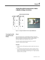
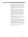
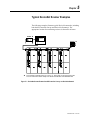
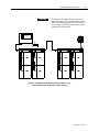
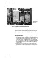
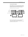
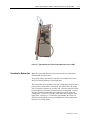
1
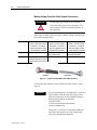
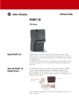
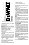
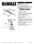
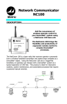
DeviceNet™ Medium Voltage CONTROLLERS INSTALLATION MANUAL Bulletin 1500/1900 Important User Information Read this document and the documents listed in the Additional Resources section about installation, configuration, and operation of this equipment before you install, configure, operate, or maintain this product. Users are required to familiarize themselves with installation and wiring instructions in addition to requirements of all applicable codes, laws, and standards. Activities including installation, adjustments, putting into service, use, assembly, disassembly, and maintenance are required to be carried out by suitably trained personnel in accordance with applicable code of practice. If this equipment is used in a manner not specified by the manufacturer, the protection provided by the equipment may be impaired. In no event will Rockwell Automation, Inc. be responsible or liable for indirect or consequential damages resulting from the use or application of this equipment. The examples and diagrams in this manual are included solely for illustrative purposes. Because of the many variables and requirements associated with any particular installation, Rockwell Automation, Inc. cannot assume responsibility or liability for actual use based on the examples and diagrams. No patent liability is assumed by Rockwell Automation, Inc. with respect to use of information, circuits, equipment, or software described in this manual. Reproduction of the contents of this manual, in whole or in part, without written permission of Rockwell Automation, Inc., is prohibited. Throughout this manual, when necessary, we use notes to make you aware of safety considerations. WARNING: Identifies information about practices or circumstances that can cause an explosion in a hazardous environment, which may lead to personal injury or death, property damage, or economic loss. ATTENTION: Identifies information about practices or circumstances that can lead to personal injury or death, property damage, or economic loss. Attentions help you identify a hazard, avoid a hazard, and recognize the consequence. IMPORTANT Identifies information that is critical for successful application and understanding of the product. Labels may also be on or inside the equipment to provide specific precautions. SHOCK HAZARD: Labels may be on or inside the equipment, for example, a drive or motor, to alert people that dangerous voltage may be present. BURN HAZARD: Labels may be on or inside the equipment, for example, a drive or motor, to alert people that surfaces may reach dangerous temperatures. ARC FLASH HAZARD: Labels may be on or inside the equipment, for example, a motor control center, to alert people to potential Arc Flash. Arc Flash will cause severe injury or death. Wear proper Personal Protective Equipment (PPE). Follow ALL Regulatory requirements for safe work practices and for Personal Protective Equipment (PPE). Allen-Bradley, Rockwell Software, Rockwell Automation, and TechConnect are trademarks of Rockwell Automation, Inc. Trademarks not belonging to Rockwell Automation are property of their respective companies. Table of Contents Chapter 1 DeviceNet Medium Voltage Controller Overview .......................... 1-1 Chapter 2 Designing Cable Systems ............................................................... 2-1 Medium Voltage Controller Cable System Construction ..................... 2-2 Chapter 3 DeviceNet Cable System Layout for Medium Voltage Controller Structures ......................................................................................... 3-1 Terminating Resistors ......................................................................... 3-2 Installing Terminating Resistors .......................................................... 3-3 Chapter 4 Linking DeviceNet Communication Cables in Medium Voltage Controllers ........................................................................................ 4-1 Connecting DeviceNet to Equipment Remote from the Medium Voltage Controller Line-up ............................................................................... 4-2 Re-locating Termination Resistors ...................................................... 4-4 Chapter 5 Typical DeviceNet Scanner Examples ........................................... 5-1 Chapter 6 DeviceNet Power Supply.................................................................. 6-1 Connecting Power Supplies – Remote or in the Medium Voltage Controller Line-Up.............................................................................. 6-1 Network Grounding at the Power Supply ............................................ 6-2 Best Grounding Practice ..................................................................... 6-2 Connecting Two Power Supplies ........................................................ 6-3 Chapter 7 System Commissioning and Software Illustration ....................... 7-1 DeviceNet Tool Box ............................................................................ 7-1 System Commissioning Checklist ....................................................... 7-2 DeviceNet Software Installation Checklist .......................................... 7-3 Chapter 8 Filling a Prepared Space in a Medium Voltage Controller Line-Up with DeviceNet ................................................................................. 8-1 General .............................................................................................. 8-1 Procedure for Top Unit ....................................................................... 8-1 Procedure for Bottom Unit .................................................................. 8-3 Software Update ................................................................................. 8-4 IntelliCENTER® Software Update ...................................................... 8-4 Appendix A How to Find Electronic Data Sheets (EDS) .................................... A-1 1500-IN057C-EN-P – June 2013 Chapter 1 DeviceNet Medium Voltage Controller Overview This document describes the cable system construction and components associated with a DeviceNet™ network that is factory installed in Bulletin 1500/1900 CENTERLINE® and IntelliCENTER® Medium Voltage (MV) controllers. Refer to other documentation provided with the MV controller for general information on the installation, use and maintenance of this equipment. ATTENTION Before performing any service or maintenance activities on MV controller sections, disconnect all power sources. Use suitable personal protective equipment (PPE) per local codes or regulations. Failure to do so may result in serious injury or death. The information included in this document is specific to medium voltage controllers. For general information related to DeviceNet, refer to the following publications: DeviceNet Selection Guide DNET-SG001_-EN-P DeviceNet Media, Design and Installation Guide DNET-UM072_-EN-P The underlined alpha character in these catalog numbers designates the latest revision at the time of this printing. The character will increase alphabetically with successive revisions. Always order and use the latest revision available. 1500-IN057C-EN-P – June 2013 1-2 DeviceNet Medium Voltage Controller Overview 1500-IN057C-EN-P – June 2013 Chapter 2 Designing Cable Systems When designing DeviceNet systems, it is necessary to consider the following (refer to publication DNET-UM072_-EN-P for additional requirements): Number of nodes does not exceed 64, with three nodes reserved for scanner (node 00), PC (node 62), and new device (node 63). Total power load and distribution points do not exceed 8A Total trunk length does not exceed the maximum allowable per the network baud rate: 246 feet (75 m) at 500 kbps or 492 feet (150 m) at250 kbps. Cumulative drop length does not exceed the maximum allowable per the network baud rate: 128 feet (39 m) at 500 kbps or 256 feet (78 m) at 250 kbps. Individual drop lengths do not exceed 20 feet (6 m) I MPORT ANT For IntelliCENTER, 500 kbps provides optimum performance, but 250 kbps may be used. (125 kbps is not possible). A separate DeviceNet network is recommended for each low voltage or medium voltage controller line-up, to simplify network and medium voltage controller design. This approach generally allows the network to operate at the maximum speed (500 kbps) and reduces the likelihood of encountering limits for node count, power consumption, and cable lengths. The DeviceNet should be bridged to ControlNet or Ethernet (using optional hardware) in the MV controller if the line-up is to be located beyond the maximum DeviceNet trunk length. 1500-IN057C-EN-P – June 2013 2-2 Designing Cable Systems Medium Voltage Controller Cable System Construction Do not apply high voltage to any installed DeviceNet cable system or its connectors. The high voltage will destroy internal capacitors in the connectors. ATTENTION Three types of media (cable) are used in medium voltage controllers for DeviceNet communication: Type Use Part number Flat • Class 1, 600 volts, 8 amps • 4 conductor – no shield or bare wire required in Class 1 DeviceNet MV Controllers Trunk lines and drop lines 1485C-P1E75 (75 m spool) 1485C-P1E200 (200 m spool) 1485C-P1E420 (420 m spool) Round • Class 1, 600 volts, 8 amps • 4 conductor – no shield or bare wire required in Class 1 DeviceNet MV Controllers Connecting units to DeviceNet ports (unit drop lines) 1485C-P1-B50 (50m spool) Flat cable Round • Class 1, 600 volts, 8 amps • 4 conductor – no shield or bare wire requred in Class 1 DeviceNet MV Controllers Trunk line for extending trunk beyond MV Controllers Belden 7896A Round cable Figure 2.1 – Typical DeviceNet Media Used in MV Controllers For flat cable specifications, refer to publication 1485-CG001_-EN-P, page 10. I MPORTANT It is not recommended to use both Class 1- and Class 2-rated cables within the same DeviceNet system. These two cable types are not compatible because the following properties are different: • Insulation class • Overcurrent protection requirements • Network transmission Using Class 1- and Class 2-rated cables within the same DeviceNet system can result in application, code, and communication problems. 1500-IN057C-EN-P – June 2013 Chapter 3 DeviceNet Cable System Layout for Medium Voltage Controller Structures The DeviceNet trunk line assembly is mounted in a 6 inch by 6 inch low voltage wireway, which is mounted on the top of the main structure. (Refer to Figure 3.1). NOTE It may be necessary to remove the low voltage wireway, to prepare the structure for shipment. It is then the responsibility of the end-user to properly re-install the low voltage wireway The DeviceNet drop lines are routed into the low voltage panels of each starter unit by connecting to the trunk line within the low voltage wireway. The connection points in the low voltage wireway are ―qui ck connect‖ type Chet-Magnum connectors. The trunk line is typically terminated at each end of the line-up, using termination resistors (see page 3-2). The connection of the trunk line in adjacent controller structures is facilitated using the same Chet-Magnum connectors (see Chapter 4). Each controller unit has two independent DeviceNet connection points within the low voltage panel for that unit. The devices installed within the controller low voltage panel are connected using these points. Please refer to Figure 3.1, for an example of how the DeviceNet trunk and drop lines are routed within the structure of the medium voltage controllers. 1500-IN057C-EN-P – June 2013 3-2 DeviceNet Cable System Layout for Medium Voltage Controller Structures Trunk Line Male Linking Plug Female Linking Plug Drop Line Jumper Drop Line LV MV LV MV Drop Line Jumper Figure 3.1 – Typical 2-High MV Section with DeviceNet Trunk and Drop Lines. Terminating Resistors ATTENTION Before performing any service or maintenance activities on MV MCC sections, disconnect all power sources. Terminating resistors are necessary at the ends of the trunk line to reduce reflections of the communication signals on the network. The DeviceNet network will operate correctly only when there are exactly two terminating resistors, one at each end of the trunk line. Terminating resistors must be equal to 121 ohms 1%, 1/4W, metal film (terminating resistor part number 1485A-C2). MV controller line-ups ship with the terminating resistors installed at opposite ends of the trunk line, located in the horizontal low voltage wireway (on top of structure). A male plug connector with a terminating resistor is connected at the right end of the trunk as shown in figure 3.2B. A female plug connector with a terminating resistor is connected at the left end of the trunk as shown in figure 3.2A. The resistors are inserted in the second terminal from each end (connected to the white and blue conductors) of both plugs (see diagram below). 1500-IN057C-EN-P – June 2013 DeviceNet Cable System Layout for Medium Voltage Controller Structures Figure 3.2A – Left Termination Resistor 3-3 Figure 3.2B – Right Termination Resistor Terminating resistor (part number 1485A-C2) BLACK BLUE RED WHITE No Shield or bare wire required in class 1 DeviceNet MCCs Five-terminal plug connector Part # 22186-084-01 with jack screws (Left Side) Part #22105-006-012 with jack screws (Right Side) Figure 3.3 – Five Terminal Plug Connector Installing Terminating Resistors When installing terminating resistors, apply the following two rules: 1. Use only two terminating resistors in any network 2. Install terminating resistors at the ends (communication and/or physical) of the trunk line located in the overhead horizontal wireway. Incorrect placement of terminating resistors and/or using more than two will cause improper network operation and result in communication losses. 1500-IN057C-EN-P – June 2013 3-4 DeviceNet Cable System Layout for Medium Voltage Controller Structures When the leftmost section is one end of trunk line, install the terminating resister in the leftmost connector. This end requires a female connector. When the rightmost section is one end of trunk line, install the terminating resister in the rightmost chetmag. This end requires a male connector. LV MV LV MV Figure 3.4 – Typical Termination Resistor Locations The above diagram illustrates the common equipment configuration and the correct placement of the terminating resistors. The number of and type of sections shown is arbitrary and for illustration purposes only. Drawings are not to scale. 1500-IN057C-EN-P – June 2013 Chapter 4 Linking DeviceNet Communication Cables in Medium Voltage Controllers Figure 4.1 – Joining the DeviceNet Trunk Line in Adjacent MV Sections Connecting DeviceNet within MV Controller Line-up General This section describes the recommended procedure for connecting DeviceNet communication cables (trunk lines) in MV controllers. The number of and type of sections shown above is arbitrary and for illustration purposes only. Drawings are not to scale. If you have questions about linking the trunk line in your MV controllers, contact technical support. Procedure 1. Join the sections, following the procedures stated in the starter user manual. 2. To link the DeviceNet trunk lines lines between separate sections, connect the linking plug from the right section into the left section linking receptacle (chetmag). Refer to Figure 4.1. Torque connector screws to 5 lb.-in. (0.6 Nm). 1500-IN057C-EN-P – June 2013 4-2 Linking DeviceNet Communication Cables in Medium Voltage Controllers 3. When joining new sections to an existing MV MCC, remove the terminating resistor from the original end section (the one to which new sections were just joined). Install the terminating resistor according to the information supplied in the section ― Terminating Resistors‖ and ― Installing Terminating resistors‖ . 4. When new sections are added, always do the following design calculations: Check the total number of nodes. See ―De signing Cable Systems‖ . If the number of nodes exceeds the guidelines, add a network Recalculate the total power consumption. If it exceeds 8A, add a power supply Verify cumulative trunk length. See ― Designing Cable Systems‖. Verify cumulative drop length. See ― Designing Cable Systems‖. Connecting DeviceNet to Equipment Remote from the MV Controller Line-up General This section describes the recommended procedure for connecting DeviceNet communication cables (trunk lines) in CENTERLINE and INTELLICENTER® MV controllers to equipment remote from the MV controller line-up. The DeviceNet connection will be to the end of the trunk line in the MV controller section nearest to the equipment. This effectively makes the connecting cable an extension of the trunk line. Refer to DeviceNet Media: Design and Installation Guide (Publication DNET-UM072_-EN-P) for length restrictions and associated effects on data transmission rates. Procedure Class 2 DeviceNet cable is NOT recommended for extending the trunk. Obtain approved DeviceNet cable long enough to connect between the MV controller line-up and remote equipment. The Belden Class 1 shielded round trunk cable, Belden 7896A, is recommended. When using this cable use trunk length limits for the flat cable. Refer to DeviceNet publications such as DN-6.7.2-MAY99 for details about attaching connectors to cables. To strip flat cable, make a shallow cut on each flat surface and edge. Flex the cable jacket to complete the break, then pull the jacket free from the wires. Strip away approximately ¼ inch (6.35mm) insulation from each of the four conductors. 1500-IN057C-EN-P – June 2013 Linking DeviceNet Communication Cables in Medium Voltage Controllers 4-3 1. Determine the safest and most convenient place to access the DeviceNet cable terminating point in the remote equipment. Drill the necessary cabinet or cover plate opening. Terminate the DeviceNet cable at the MV controller line-up in the LV wireway using the chetmag at the rightmost section or at the leftmost section. Remove the terminating resistor plug from the chetmag in the LV wireway, and save it for correct installation when all DeviceNet connections are complete. 2. If the termination is to another DeviceNet cable, proceed to step 3. If the termination is at a DeviceNet module (ControlNet to DeviceNet Linking device [CN2DN] or modules for 1771, SLC500, or ControlLogix PLCs), plug the cable connector into the module connector. Torque connector screws to 5 lb.-in. (0.6Nm). If this connection is the termination of the DeviceNet cable (end of the trunk line), remove the resister from the terminating resistor plug (from step 1). Insert the resister into the terminals on the plug connector to terminate the white and blue conductors (second hole from each end). 3. If the termination is to another DeviceNet cable, remove the terminating resistor from the other cable (if one is present). Insert the new cable connector into the existing cable connector. Torque connector screws to 5 lb.-in. (0.6Nm). 4. Following the rules and guidelines required in The Planning and Installation Manual for DeviceNet, make certain that terminating resistor (equal to 121ohms 1%, 1/4W, metal film and supplied in the first and last sections of the MV controller line-up) are plugged in at the far left and far right ends of the DeviceNet trunk line. 5. If the shielded round trunk cable (Belden Class 1) is used, ensure that the shield is connected to ground at one end of the cable only. 6. For connecting other equipment not referenced above, please consult Rockwell Automation technical support 1500-IN057C-EN-P – June 2013 4-4 Linking DeviceNet Communication Cables in Medium Voltage Controllers Re-location of Termination Resistors General If any MV controller units are relocated such that the termination resisters are no longer at the end of the trunk line, then they must be removed and re-installed at the end of the lineup. A unit that is added to either end of the lineup must also have the termination resister relocated from the existing end unit to the added unit. The number of and type of sections shown below is arbitrary and for illustration purposes only. Drawings are not to scale. If you have questions about re-installing termination resisters into the trunk line of your MV controller line-up, contact Rockwell Automation technical support. Termination resistor moved to end unit when adding unit(s). Unit added to left end of line-up Existing left end section of lineup Existing right end section of lineup Unit added to right end of lineup Figure 4.2 – Re-location of Terminating Resistors (when additional units are added to MV Controller Line-up) 1500-IN057C-EN-P – June 2013 Chapter 5 Typical DeviceNet Scanner Examples The following examples illustrate typical DeviceNet networks, including both the MV controller line-up and DeviceNet Scanner(s). The appropriate location for terminating resistors is shown for reference. 121Ohms DeviceNet Scanner LV MV LV MV LV MV LV MV LV MV LV MV LV MV LV MV You must attach a terminating resistor of 121 ohms, 1%, 1/4W or larger, to each end of the trunk line. You must connect these resistors directly across the blue and white wires of the DeviceNet cable. Figure 5.1 – DeviceNet Scanner Remote from MV Controller Line-up; one DeviceNet Network 1500-IN057C-EN-P – June 2013 5-2 Typical DeviceNet Scanner Examples 121Ohms DeviceNet Scanner 121 Ohms 121 Ohms DeviceNet Scanner 121Ohms LV MV LV MV LV MV LV MV LV MV LV MV You must attach a terminating resistor of 121 ohms, 1%, 1/4W or larger, to each end of the trunk line. You must connect these resistors directly across the blue and white wires of the DeviceNet cable. Figure 5.2 – DeviceNet Scanners Remote from MV Controller Line-up; Two DeviceNet Networks 1500-IN057C-EN-P – June 2013 Typical DeviceNet Scanner Examples I MPORTANT 5-3 To minimize the impact of DeviceNet trunk length limitations, it is recommended that each MCC have an independent DeviceNet network. Accordingly, the following architecture shown must be used with caution. DeviceNet Scanner 121 Ohms 121Ohms LV MV LV MV LV MV LV MV LV MV LV MV LV MV LV MV Figure 5.3 – DeviceNet Scanner Remote from MV Controller Line-up; one DeviceNet Network; Divided MV Controller Line-ups 1500-IN057C-EN-P – June 2013 5-4 Typical DeviceNet Scanner Examples 1500-IN057C-EN-P – June 2013 Chapter 6 DeviceNet Power Supply I MPORT ANT The DeviceNet cable system requires a 24Vdc power source to operate. The power supply must: • Meet NEC Class 1 requirements as outlined in Article 725 • Be DeviceNet compatible as specified in the ODVA requirements Power supplies that do not satisfy both points listed above can result in damage to the DeviceNet signal and components, as well as failure to comply with NEC, local codes, and inspection. A power supply unit that meets all DeviceNet requirements can be supplied with the MV controller line-up – catalog option number 12DNPS_ (consult your local Rockwell Automation salesperson or distributor). It is available in two configurations: with circuit breaker only (requires a separate 110-120V, 50/60 Hz, 100VA source) and circuit breaker with 500VA control transformer. A cable connects the output of the power supply to a DeviceNet port in the unit. The cable is already connected when the power supply unit ships installed in the MV controller line-up. Remote power supplies should meet the following requirements (refer to DNET-UM072_-EN-P for additional information): Rated 24 Vdc ( ±1%) Rise time of less than 250 ms to within 5% of its rated output voltage Current limit protection Sized correctly to provide each device with its requried power – each device typically requires 65-195 mA Derated for temperature using the manufacturer’s guidelines Connecting Power Supplies – Remote or in the MV Controller Line-up Connecting power supplies according to these guidelines will minimize voltage drops in the DeviceNet system and ensure proper supply voltage to system devices. Refer to DeviceNet Media: Design and Installation Guide (Publication DNET-UM072_-EN-P) for detailed connecting instructions. Connect the power supply to the DeviceNet system where it is convenient (no location restrictions). 1500-IN057C-EN-P – June 2013 6-2 DeviceNet Power Supply Note: Optional equipment is also shown. Figure 6.1 – LV Panel of Incomer with DeviceNet Power Supply Network Grounding at the Power Supply The DeviceNet cable must be grounded at only one location. The ideal choice is at the power supply. Ground the power supply and 24 Vdc common (black wire). Best Grounding Practice 1500-IN057C-EN-P – June 2013 If the power supply comes installed in the MV controller, the black 24 Vdc common terminal is grounded to a TE ground within the MV controller; the TE ground is connected to the cabinet ground bus. To improve the grounding, disconnect the black 24Vdc common from the TE ground then use #8 AWG green wire and ground the black 24 Vdc common terminal to a very stable ground external to the MV controller line-up. If the power supply is external, use the #8 AWG green wire and ground the black 24 Vdc common terminal to a very stable ground. DeviceNet Power Supply 6-3 Connecting Two Power Supplies When an additional 24 Vdc Class 1 power supply must be installed for MV controller line-ups, the red trunk conductor between the power supplies must be broken. Locate a linking connector between sections and disconnect the red conductor (refer to the following figure). Ground only ONE of the two power supplies. break Red V+ White CAN_H Blue CAN_L Black V- (common) Power Supply Power Supply Figure 6.2 – Connecting Two DeviceNet Power Supplies MCC line-ups with more than 10 2-Hi sections could exceed the 39 meters (128 feet) cumulative drop limit to support 500 kbps communications. When the trunk length exceeds this limit, 250 kbps communications should be specified. 1500-IN057C-EN-P – June 2013 6-4 DeviceNet Power Supply 1500-IN057C-EN-P – June 2013 Chapter 7 System Commissioning and Software Installation DeviceNet Tool Box The following optional items are suggested for IntelliCENTER and DeviceNet MV controller installation and maintenance: Hand tools—high-quality small-tip screwdriver, side-cutter, needlenose pliers, wire stripper Terminating resistors equal to 121 ohms 1%, 1/4W, metal film – part number 1485A-C2 Five-terminal plug (part number PN 942154-05 with jack screws; PN 942153-05 without jack screws) Five-terminal receptacle (part number 22186-084-01) Ten foot (3 m) Class 1 round cable—for connecting devices to ports (part number 1485C-P1-B50 for a 50 m spool) Short length of Class 1, 8 A round adapter cable with five-terminal receptacle on each end Ten-foot (3 m) personal computer (PC) cable with five-terminal plug on each end—part number 2100H-ICPC120 Portable DeviceNet network for off-line testing and node commissioning—required parts: small power supply (24 Vdc, 500 mA); DeviceNet cable; DeviceNet connectors; and terminating resistors Digital multi-meter—Fluke 79 or equivalent ODVA DeviceNet monitor—order form available at http:// www.ab.com/intellicenter/instructions or contact product support DeviceView hand-held configurator—part number 2707-DNC Power supply for hand-held configurator—part number 2707-PS120 Cable for hand-held configurator—part number 2707-NC13 Laptop personal computer with the following software: RS Networx for DeviceNet RS Linx ControlFlash update software RS Logix 5 for PLC/5 RS Logix 500 for SLC and MicroLogix RS Logix 5000 for ControlLogix IntelliCENTER software 1500-IN057C-EN-P – June 2013 7-2 System Commissioning and Software Installation System Commissioning Checklist When installing a DeviceNet MV controller line-up, use the following checklist before applying power to the network: DeviceNet Software Installation checklist Number of nodes does not exceed 64, with three nodes reserved for scanner (node 00), PC (node 62), and new device (node 63) Individual drop lengths do not exceed 20 feet (6 m) Cumulative drop length does not exceed the desired network baud rate limit: 128 feet (39 m) at 500 kbps or 256 feet (78 m) at 250 kbps Total trunk length does not exceed the maximum allowable per the network baud rate: 246 feet (75 m) at 500 kbps or 492 feet (150 m) at 250 kbps Verify that all devices are programmed to the same baud rate and autobaud is disabled Verify that terminating resistors are in place at the trunk line terminations and measure for proper resistors (121 ohms, 1/4 W, 1%, metal film) Verify that the power supply for the system is 24 Vdc Total power load and distribution points do not exceed 8 A The system has one, and only one, earth ground for the VThere is an earth ground connection All connections are inspected for loose wires, opens, and shorts The following general steps, along with references for more information, are provided to assist with the DeviceNet software installation process. 1. Install the communication card in your personal computer. 2. Load the Windows hardware drivers for the communication card. 3. Load RSNetworx™ for DeviceNet and RSLinx software. 4. Configure the RSLinx driver. Within the RSWho function, make sure no unrecognized devices (i.e., ―? ‖ symbols) appear for any devices. If an unrecognized device appears, load the Electronic Data Sheet (EDS) file. See the ― How to Find Electronic Data Sheets (EDS)‖ in Appendix A. I MPORT ANT 1500-IN057C-EN-P – June 2013 Do not leave the RSWho constantly browsing. Be sure to close the RSWho screen or disable the Autobrowse. System Commissioning and Software Installation 7-3 5. Use RSNetworx for DeviceNet to program and configure devices (e.g., full load current, acceleration rate, etc.). Do not download to a device before uploading from that device. Otherwise, the node and baud rates will be overwritten, requiring each device to be individually manually reprogrammed. Make sure to set communication-loss behavior for each device. I MPORT ANT RSNetworx for DeviceNet can also be used to change baud rates and node numbers, but remember that the devices are normally pre-programmed at the factory. 6. Use RSNetworx for DeviceNet to program the DeviceNet scanner (if required). I MPORT ANT When using a 2100-GK61 communication module, keep in mind that there are two extra bytes of receive data for the inputs on the 2100-GK61. Make sure the number of bytes in the scanner configuration corresponds with the number of bytes in the device. See the 2100-GK61 user manual (publication 2100UM001_-EN-P, chapter 4) for more details. 7. Write the PLC program (if required). 8. If IntelliCENTER software is provided, load per the IntelliCENTER Software User Guide (Publication 2100-UM002_-EN-P). 1500-IN057C-EN-P – June 2013 7-4 System Commissioning and Software Installation 1500-IN057C-EN-P – June 2013 Chapter 8 Filling a Prepared Space in a MV Controller Line-up with DeviceNet General Use this section when upgrading a Bulletin 1500 prepared space in a DeviceNet MV controller with a controller kit. Each DeviceNet component is factory wired within the controller kit and has a communication cable that plugs into the device on one end and the other end plugs into a DeviceNet port located on the flat vertical cable assembly mounted on the left side of the low voltage panel. The procedure varies depending on whether the controller kit is to fill the top or bottom location of a 2-unit structure. Note: There is no need to re-evaluate the cumulative drop for this network. The incremental increase in cumulative drop due to the addition of the controller kit was taken into account when the MV controller line-up was built. Note: When using IntelliCENTER software, new units must be added to the software by installing the data disk(s) that accompanies the controller kit. If an existing unit is moved, the user must update this change in the IntelliCENTER software. Refer to IntelliCenter software manual, pubication 2100-UM002_-EN-P. Procedure for Top Unit Note: This procedure requires the bottom unit to be temporarily disconnected from DeviceNet. The prepared space does not have any DeviceNet connections. In order to link the bottom unit to the DeviceNet network, a round cable was factory installed between a port in the trunk line located in the top horizontal wireway and a port in the bottom low voltage panel (see Figure 8.1). This cable must be unplugged at both ends and removed in order to install and connect the controller kit to the network. Each end of the vertical flat cable assembly on the low voltage panel of the kit has a port to which a round cable is connected. The round cables are provided with a 5-terminal connector on their loose end. Once the controller kit has been installed, the DeviceNet connections may be completed. Connect the round cable at the top of the low voltage panel to the closest port on the trunk line located in the horizontal wireway (see Figure 8.2). Then connect the round cable at the bottom of the low voltage panel to the port located at the top of the bottom low voltage panel. 1500-IN057C-EN-P – June 2013 8-2 Filling a Prepared Space in a Medium Voltage Controller Line-up with DeviceNet Figure 8.1 – Prepared Space with “Bypass” Cable to Lower Panel 1500-IN057C-EN-P – June 2013 Figure 8.2 – Trunk Line and Drop Line cable Filling a Prepared Space in a Medium Voltage Controller Line-up with DeviceNet 8-3 Figure 8.3 – Typical Starter Kit LV Panel for DeviceNet (lower unit of 2-High) Procedure for Bottom Unit Note: This procedure does not require the top unit to be temporarily disconnected from DeviceNet. The prepared space does not have any DeviceNet connections or any DeviceNet wiring entering or crossing the unit. The vertical flat cable assembly on the low voltage panel of the kit has a port to which a round cable is connected. The round cable is provided with a 5-terminal connector on its loose end. Once the controller kit has been installed, the DeviceNet connections may be completed. Connect the loose end of the round cable to the bottom port of the upper low voltage panel. If a device is already connected to the lower port of the upper panel, a splitter or ―Y ‖ connector (part number 40122-304-51) must be inserted into this port to accommodate the cable connection to the lower low voltage panel. 1500-IN057C-EN-P – June 2013 8-4 Filling a Prepared Space in a Medium Voltage Controller Line-up with DeviceNet Software Update After installing a controller kit in an IntelliCENTER MV line-up, the user must update the IntelliCENTER software by following these directions. This is done by merging the data disks for the controller kit(s) with the existing IntelliCENTER database. Please refer to the IntelliCenter software manual 2100-UM002_-EN-P. IntelliCENTER Software Update IntelliCENTER software is a PC-based application used to monitor and troubleshoot Centerline low and medium voltage controllers. It consists of two software CDs: Application CD Data CD The Application CD is the same for both low and medium voltage controllers. The Data CD is unique, and it is provided for each low or medium voltage line-up. A Data CD can also be provided for each addition to a line-up or a medium voltage controller kit. If any of the following hardware changes are made to your medium voltage line-up, you must update the IntelliCENTER software installed on your PC: Installation of a new line-up, that you wish to access within an existing IntelliCENTER software workspace Addition of new structures, to an existing line-up Addition of a controller kit to a prepared space Re-location of a structure (i.e. moving from left side to right side of line-up) Please refer to Rockwell Automation publication 2100-UM002_-EN-P for instructions on how to update the IntelliCENTER software, using the new/updated Data CDs. 1500-IN057C-EN-P – June 2013 Appendix A How to Find Electronic Data Sheets (EDS) Background After installing IntelliCENTER software, an Electronic Data Sheet (EDS) file must be registered for each unique device in the MCC. This section details how to perform that task. Definition of EDS Files EDS files are simple text files used by network configuration tools— such as DeviceNetManager™, RSNetworx, and IntelliCENTER software—to help identify products and easily commission them on a network. EDS files describe a product’s device type, product revision, and configurable parameters on a DeviceNet or ControlNet network. Necessary EDS Files Installing EDS Files The data CD supplied with your IntelliCENTER contains a directory (<cdrom>:\EDS) of all EDS files necessary for the devices in your IntelliCENTER. The EDS files are installed with a program from Rockwell Software that is also on the IntelliCENTER data CD (in the same directory as the EDS files). This program is called ―RS HWare.exe.‖ To install the EDS files: 1. Run the program RSHWare.exe. 2. Click Add/Remove. 3. Select Register an EDS file. Click Next. 4. Select Register a directory of EDS files. 5. Browse to the EDS directory on the data CD. 6. Click Next. 7. The Installer will display the test results. Click Next to continue. 8. The Installer will allow you to change the graphic image for each device. Click Next to continue. 9. The Installer will display the final task summary. Click Next to continue. 10. Click Finish when completed. 1500-IN057C-EN-P – June 2013 A-2 How to Find Electronic Data Sheets (EDS) Finding EDS Files for Other Devices 1500-IN057C-EN-P – June 2013 The program CD also contains a directory called EDS. This directory contains all EDS files sorted by the product family or classification. EDS files can be obtained at http://www.ab.com/networks/eds. Medium Voltage Products, 135 Dundas Street, Cambridge, ON, N1R 5X1 Canada, Tel: (1) 519.740.4100, Fax: (1) 519.623.8930, www.ab.com/mvb Publication 1500-IN057C-EN-P – June2013 Supersedes Publication 1500-IN057B-EN-P – January 2007 Copyright © 2013 Rockwell Automation, Inc. All rights reserved. Printed in Canada.