1
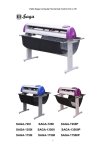
C SERIES USER’S MANUAL
C12/24/30/48
CUTTING PLOTTER
All Rights Reserved to Foison Technology Ltd.
1
C SERIES USER’S MANUAL
Preface
Preface
Chapter One Standard Parts
1.1 Standard Accessories with Cutter…………………………………………………………5
1.1.1 Accessories list…………………………………………………………………………….5
1.1.2 C48 Sketch for Vertical Stands Installation……………………………………………..6
1.2 Optional Accessories………………………………………………………………………..6
1.2.1 Software…………………………………………………………………………………...6
1.2.2 Cutting Mat……………………………………………………………………………….6
1.2.3 Blade holder and the knife……………………………………………………………….7
1.2.4 C24 Stand Installation Sketch……………………………………………………………7
Chapter Two Safety Precaution
2.1 Safety Precaution……………………………………………………………………………8
Chapter 3 Features
Product Parameters……………………………………………………………………………11
Chapter Four Parts Name and Function
4.1 Front View ( C-24 )………………………………………………………………………...12
4.2 Back View ( C-24 )…………………………………………………………………………13
Chapter Five Cutter Installation
5.1 Installation and connection……………………………………………………………….14
5.1.1 Cutting Environment……………………………………………………………………14
5.1.2 Connect signal cable to the PC. ………………………………………………………...14
5.1.3 USB Driver Installation. ………………………………………………………………...15
5.1.4 Power Cable Connection. ……………………………………………………………….15
5.2 Cutting Media Installation. ……………………………………………………………….15
5.3 Tools Installation.. …………………………………………………………………………17
5.4 Plot Pen Installation……………………………………………………………………….18
Chapter Six General Settings and Operation
6.1 Work Status Descriptions………………………………………………………………….19
6.1.1 Online/Offline.……………………………………………………………………………19
6.1.2 Carriage Movement. …………………………………………………………………….19
6.1.3 Original Point Setting……………………………………………………………………20
6.1.4 Bounded system………………………………………………………………………….20
6.1.5 Back to the original point automatically……………………………………………….21
6.1.6 Reset Default parameter………………………………………………………………...21
6.2 Online Keyboard Function Definition……………………………………………………21
2
C SERIES USER’S MANUAL
6.3 Offline Status Description…………………………………………………………………22
6.4 Menu Operation Description……………………………………………………………...23
6.4.1 Power on Display………………………………………………………………………...23
6.4.2 Online/Offline Operation………………………………………………………………..23
6.4.3 Speed and Knife Force Setting…………………………………………….……………24
6.4.4 Knife drop/raise Test…………………………………………………………………….25
6.4.5 Test Rectangle Cutting Operation………………………………………………………25
6.4.6 Pause Button Operation…………………………………………………………………26
6.4.7 Online-change Speed and Knife Force Operation……………………………………..27
6.4.8 Repeat Function………………………………………………………………………….28
6.4.9 Port Setting……………………………………………………………………………….28
6.4.10 X, Y Scale Setting……………………………………………………………………….29
6.4.11 Laser contour cut setting……………………………………………………………….30
Chapter Seven Troubleshooting………………………………………………………...31
Chapter Eight Appendix………………………………………………………………….32
Appendix USB Port Setting and Replacement……….……………………………………...35
3
C SERIES USER’S MANUAL
Preface
Thank you for buying our FOISON cutter plotter.
In the C series cutter user’s manual, it includes the cutter features, parts name, and the
necessary information prior operating, and the basic operation, such as how to turn on/off the
electricity, how to set the cutter etc.
Prior reading the content, please read the following items
- Parts listing
- Safety precautions
In order to use the cutter correctly and safely, please read above relative contents, and leave
the manual at where you can catch conveniently.
Prior operating the FOISON cutter, please thoroughly read the manual, which will help you
acquire performance of the machine and make best of its functions, please keep the manual well
for future reference.
Without our permission, any individual or organization shall not duplicate or promulgate
the contents of this manual.
We reserve the rights to amend this manual or specification of the products without
advising you. If you need precise technical information, welcome to call us or visit to our
website www.foison.net.cn to acquire the latest information.
We have made great effort to accurate our manual, if you find anything wrong in printing or
other respects, please do not hesitate to notify us or local agent of our company.
4
C SERIES USER’S MANUAL
Chapter One Standard Parts
The following cutter standard accessories with the cutter can be available in a packing box.
If you find any damaged, please contact with the local distributor or our company. The other
following optional accessories should be ordered optionally.
1.1 Standard Accessories with Cutter
1.1.1 Accessories list
Number
Item
Quantity
1
Power cable
1
2
Signal cable
1
3
USB cable
1
4
Rotary tool apron
1
5
Plot pen
1
6
45° Blade
2
7
60° Blade
1
8
Lead
2
9
Certificate of Quality
1
10
Warranty card
1
11
Documentary of
assembling line of the
vinyl cutter
1
12
CD disk
1
13
Sample
1
Icon
5
C SERIES USER’S MANUAL
1.1.2 C48 Sketch for Vertical Stands Installation
Only C48 is equipped with stand, the stands is optional for C24
1.2 Optional Accessories
1.2.1 Software
Number
Item
Quality
1
FOISON FLEXI
STARTER
1
2
Artcut Software
1
3
SignBlazer
1
4
Signcut-X2
1
5
PCSIGN Letter
1
Icon
1.2.2 Just Standard Accessories with C12-L , Optional Accessories for other size cutters.
6
Number
Item
Quality
1
Cutting Mat
1
C SERIES USER’S MANUAL
1.2.3 Blade holder and the knife(Please see 5.3.1 of specific usage)
ROLAND blade holder:
;
ROLAND knife:
;
FOISON blade holder:
;
FOISON 60ºknife
联机状态
FOISON 45ºknife
( The picture is for reference, the color and dimension subject to products. )
1.2.4 C24 Stand Installation Sketch
The stand for C24 shown as above
7
C SERIES USER’S MANUAL
Chapter Two Safety Precaution
The following icons are used in the manual; aims to make sure the user operate the cutter
properly to avoid damaged the cutter. Please comply with the explanation of the icon.
2.1 Safety Precaution
Definition of Warning Symbols:
serious casualty :
WARNING
Any improper operation possibly results in hazard
of life.
Light hazard in life or equipment damaged:
CAUTION
Any improper operation possibly results in hazard
Of life or the equipment.
Definition of Warning Symbols:
The symbol “
” is prepared to arouse operator's highly attention
when in process.
The symbol “
” specifies the activities to be forbidden.
The symbol is prepared to arouse operator's highly attention. The
symbols in triangles specify the cases to be attentive. The symbol in
the left warns you of electric shock.
The symbol specifies the activities to be forbidden. The symbol in
the circle specifies the acts to be forbidden. The symbol in the left
tells you no detachment.
8
C SERIES USER’S MANUAL
Caution
Do not leak any liquid or drop
metal into the machine, such
things may result in fire.
Do not touch the knife top with
your finger to prevent injury or
perspiration of knife head.
Do not damage or random replace
the supplied power cable. Do not
excessively bend, pull, bundle the
power cable or place weight on it,
otherwise the power source may
be damaged even fire or electric
shock is thus incurred.
If you are not going to use the
machine for a long time, please
unplug the power cable from the
receptacle, otherwise fire possibly
happens.
When operating the machine, do
not place either of your hands on
capstan to avoid injury.
Place the machine on a stable
surface, otherwise the machine
may fall therefore get damaged.
To unplug the power cable from
receptacle, please hold the plug
instead of the cable, strongly
pulling of the cable possibly
results in electric shock or fire.
Any operation is forbidden in case
of storm or lighting to prevent
damaged of machine.
9
C SERIES USER’S MANUAL
Warning
Do not use the power source not meeting rating voltage, otherwise
fire or electric shock may be resulted in.
If the machine gives out smoke or unpleasing smell, or noise sounds
please do not use it .in such cases, continuing using it may result in
fire or electric shock.
Do not put out the plug when the power is on to avoid damage to the
Machine.
Make sure the machine grounded otherwise electric shock or
mechanic default may be resulted in.
10
C SERIES USER’S MANUAL
Chapter 3 Features
Product Parameters
Model
C-12
C-24
C-30
Structure
desktop
desktop/
(optional stands)
desktop/
(optional stands)
C-48
Stands
(with stands)
Max media width
415mm
720mm
850mm
1300mm
Max cutting width
305mm
610mm
740mm
1220mm
Main board
High speed Arithmetic Microprocessor, 1MB cache (4 MB is optional)
Interface
RS232C,USB
Control penal
10silica gel buttons
Driver
Digital DC, step motor, Micro-step Driver
Display
4*8 high resolution LCD
Drawing instruction
HP-GL,DMPL
Max cutting speed
600mm/s
Max cutting thickness
1mm
pressure
50g~800g (160 grades digital Adjustable)
Mechanical precision
0.025mm
Repeatable precision
< ±0.1mm
Power supply
AC90~240V/50Hz~60Hz
Positioning model
Bounded system, random original point setting
Working model
Roller
Operational environment
+5℃ ~ +35℃,relative humidity 30%~70%
Net weight
9kg
12kg
15.4kg
17.5kg
Gross weight
12.3kg
16kg
17kg
39kg
Dimension
585*265*270
890*265*270
1020*265*270
1530*265*270
Package Dimension
715*380*395
1015*380*395
1085*380*395
1575*370*430
11
C SERIES USER’S MANUAL
Chapter Four Parts Name and Function
4.1 Front View(C-24)
Carriage
Left cabinet
Transmission Shaft
Control Panel
Blade Base
Right Cabinet
Paperweight Wheel
Power Interface
Power Switch
USB Interface
12
Serial Interface
C SERIES USER’S MANUAL
4.2 Control Panel
11
1
6
5
10
4
9
8
3
7
2
1、 LCD(LCD)Display
2、 Paper Feeding Button: it is X direction button under offline; it is value“-”under
parameter menu.
3、 Original Setting Button: Press such button to fix the coordinate point under offline.
Press more than 2 seconds under “Welcome” interface, the machine will
reinitialize, all data in buffer memory will be cleared. You could go back to the
default parameter.
4、 Rightward Button: it is Y direction button under offline; it is value“-”under
parameter menu.
5、 Paper Withdrawal Button: it is X direction button under offline; it is value “+”
under parameter menu.
6、 Leftward Button: it is Y direction button under offline; it is value “+” under
parameter menu.
7、 Pause Button: Switch to pause/resume model under online working.
8、 Repeat Button: to repeat last job.
9、 Menu Button: Switch to online and menu model.
10、Online Button: Switch to online and offline model.
11、Testing Button: (Press for a short time) to up and down the knife; or (press for a
long time) to test a rectangle itself.
13
C SERIES USER’S MANUAL
Chapter Five Cutter Installation
5.1 Installation and Connection
5.1.1 Cutting Environment
Place the cutter in adequate space in case to replace some parts, output the media and
make sure ventilation.
The place for installing the cutter shown as below
Vinyl Cutter
Don’t install your cutter in the following place
- The place where is direct sunlight
- The place where is vibration
- The place where is full dust
- The place where is draught
5.1.2 Connect signal cable to the PC
To make the connection between the cutter and the computer, you are offered two
possibilities: RS232 and USB interface. For USB connection, you need to install the driver
equipped with the cutter first. (Please refer to 5.1.3)
14
C SERIES USER’S MANUAL
5.1.3 USB Driver Installation
For USB connection, you need to install the driver equipped with the cutter. Firstly, put
the disk to the driver, after the driver run by itself, click the USB DRIVER installation, or install
“USB CUTTER COM” file under USB DRIVER in the disk equipped with the cutter. After
installing successfully, connect the USB cable to computer USB port. When the computer has
found the new hardware and clew that this hardware can be used, then it means the USB driver
has been installed successfully. Please refer to the appendix for setting the port.
5.1.4 Power Cable Connection
5.2 Cutting Media Installation
Cautions of Media Preservation
- Keep the media away from direct sunlight and water when before and after unpacked.
You should keep the media in dry, shady and cool place after using it.
- Do not put the media in the vertical position, to avoid mess and damage the edge of
the media
- Do not print media in pile.
Cautions of Media Loading
- Avoid the temperature and humidity changes after unpack the box.
- According to the media feature, when low temperature, media is easy to curl, when
high temperature, it is easy to crease.
- Do not use the media when it is crease, curl or dusty.
- Do not fall or moisturize the media, otherwise it may effects the cutting quality or
result in damaging the cutter.
- Before loading the media, you should roll the media.
The cutter is both suitable for single sheet media and roll media
15
C SERIES USER’S MANUAL
5.2.1 Press down the handle of paperweight wheel behind the machine to raise the
paperweight wheel.
5.2.2 Insert the media into the space between paperweight wheel and main shaft, and pull
out the media to appropriate length from the front of the host.
5.2.3 Move the paperweight wheel to the yellow identified
area, then adjust position of the media, a distance of
about 1-10CM is set between paperweight wheel and
media to ensure good running of media
The cutter adopts high-precision transmission shaft, and pay attention to the
position of the paperweight wheel. The paperweight wheel must be fixed above the yellow
identified area on the transmission shaft.
5.2.4 Raise two handles of paperweight wheel, to make paperweight wheel down to
press paper
16
C SERIES USER’S MANUAL
5.3 Tools Installation
CAUTION
Do not touch the knife top with
your finger to preserve injury or
passivetion of knife head.
5.3.1Tool Introduction and Application
Icon
Series Number
Angle
Application
45°
C12 / 24 / 30 / 48
60°
C12 / 24 / 30 / 48
Compare with 45ºand 60ºblade of Foison
Degree
60º
45º
Using scope
big word over 20mm
Advantage
Disadvantage
More attrite than 45 degree
the quality of cutting small world and high
and Can cut thick and hard
precision picture is not better than 45
material
degree blade
Small word below 20mm high precision picture is
or high precision picture
better than60 degree blade
sharply knifepoint, the attrition is not better
than 60 degree and have large wasting when
cutting thick and hard material
5.3.2 Adjust the protruding length of the knife top as required for specific cutting media
Superficial material
面材
Base paper
底纸
Correct
Tool long protruding
Tool short protruding
Length of knife point
length of knife point
5.3.3 (1) Loosen the screw of tool carrier
(2)Assembly the tool with knife into the tool carrier
(3)When the tool is in appropriate position screw it and fix the screw.
17
C SERIES USER’S MANUAL
Knife tool
Setscrew
5.3.4 Trial run (adjusting knife press and tool)
Quality of knife immediately relate to cutting precision and life of machine. To better
your work, please use the standard knives we confirm, but not those with poor quality.
5.3.4.1 Press “Online” button to make the machine Offline.
5.3.4.2 While it’s offline, press “TEST” twice, the machine will automatically cut a small
square from the media.
5.3.4.3 Take off the square, if you fail, the square need to be further cut, because the press
is low or the protruding length of knife top is too short; If the base paper is
pierced through, it signifies that the protruding length of knife top is too long and
the press is too big. Adjust the protruding length of knife top and knife press
according to result of trial run and the description of tool installation. The most
appropriate protruding length of knife top and knife press is to cut the media
exactly but not pierced through.
5.3.4.4
Press “+”or“-”to adjust knife press.
5.4 Plot Pen Installation.
The plot pen presented with the cutter is used for drawing on the media. The operation
method is the same as the above blade holder.
18
C SERIES USER’S MANUAL
Chapter Six General Settings and Operation
6.1 Work Status Descriptions
6.1.1 Online/Offline
When the cutter is switched on, it will reset and set to online status. Press “Online” to
switch Online/Offline status. When the cutter transmits data to PC, the cutter must be in online
status. But if you need to change the parameters of the cutter or operate manually, the cutter
shall be in Offline status. The LCD shown as followings:
online status
offline status
6.1.2 Carriage Movement
When the cutter is Offline status, press “
right. press“▲
”, the carriage will move left and
”, the main shaft will move back and for the at the same time the
LCD will show X, Y step value respectively.
19
C SERIES USER’S MANUAL
6.1.3 Original Point Setting
When the carriage needs to move to the original point, press “
”, X and Y value will
set to “0”. Then the new original point is set. The cutter will begin working at the new
original point.
The relationship between Absolute Original Point and random original point:
Random Original Point
Absolute Original
6.1.4 Bounded system
The cutter adopts advance optical coupler bounded system. The following introduces
how the optical coupler takes effect.
1.
Move the carriage to the left side (right side) of the cutter; if the cutter exceeds the
work area, the limit switch takes effect automatically to prevent the carriage strike to
the cutter side. Move the carriage to right (left), the limit switch will lose effect.
2.
When the cutter is working, if the work area set in the software is too large and cause
the carriage move to the left and exceed the work area, the bounded system will
activate automatically. The cutter will stop working and the LCD displays Pause
(shown as followings). The cutter shall restart and current job can be neither save or
continue working.
Hints: In the software, please don’t set the work area that exceeds the effect work area. Also
please pay attention to position between the original point and left side of the cutter to
prevent the bounded system takes effect.
20
C SERIES USER’S MANUAL
6.1.5 Back to the original point automatically
When turn on the machine, the carriage will back to the original point automatically.
6.1.6 Reset Default parameter
Generally speaking ,. You do not need change the scales (Set Per Xp=36720
Yp=36650) . If the customer changed this incaution and want to go back to the default
parameter , just reset the deafult parameter as following :
Turn on the machine, LCD will show “Foison Welcome Ver 3.171”, press
(origin
setting button) two seconds, then it will appear “RESET”, at that time, the machine is
resetting default parameter. See default parameter as following:
“v=400mm f=30”; “Us=600mm Br=38400”;
“Xp=367200
Yp=36650”.
6.2 Online Keyboard Function Definition
1st Level Menu Keyboard Definition
Button
Function
Description
Online
Online/Offline
Press once to switch to offline status
Menu
Menu Switch
Press once and enter into Setting menu
Knife Force Increase
Press once, the knife force increases by 1 , it totally has 160 steps
Knife Force Decrease
Press once, the knife force decrease by 1 , it totally has 160 steps
Cutting Speed Increase
Press once, the cutting speed will increase by 50mm/s
Cutting Speed Decrease
Press once, the cutting speed will decrease by 50mm/s
Pause
Pause/Resume
Repeat
Knife drop/raise
If either speed or knife force is not optimized, press Pause once to
pause working, after adjusting, press once to resume working
Press once for knife dropping and press again knife raising
21
C SERIES USER’S MANUAL
Setting Mode Menu Definition
Button
Function
Description
Menu
Menu Switch
Press once and enter into Set Per menu
Baud Rate Increase
Press once and increase to a defined baud rate
Baud Rate Decrease
Press once and decrease to a defined baud rate
Idle Speed Increase
Press once the Idle Speed will increase by 50mm/s
Idle Speed Decrease
Press once the Idle Speed will decrease by 50mm/s
Set Per Menu Definition
Button
Function
Description
Menu
Menu Switch
Press once and enter into Foison status
Increase Yp Scale
Decrease Yp Scale
Increase Xp Scale
Decrease Xp Scale
If the actual cutting scale is smaller than the image size
from Y position, press this button will increase the size.
If the actual cutting scale is larger than the image size
from Y position, press this button will decrease the size
If actual cutting size is smaller than the image size, press
this button will increase the size.
If actual cutting size is larger than the image size, press
this button will decrease the size.
6.3 Offline Status Description
Offline Keyboard Function Definition
Button
Function
Description
Online
Online/Offline
Press once to switch to Foison status
Y+, Left Direction Key
Press and realize carriage move to left position
Y-, Right Direction Key
Press and realize carriage move to right position
X+, Backwards Direction Key
Press and realize main bearing move backwards
X-, Forwards Direction Key
Press and realize main bearing move forwards
Original Position Setting Key
Press once will reset X,Y to “0”, the current
position will be the original position
Test
Press for One Second
Draw/cut a tiny square
Test
Press for Two Seconds
Draw/cut a test pattern
Pause
Pause/Resume
Repeat
Repeat Last Time Work
When the cutter finish working, press this key on
offline status will repeat the same job
The left and right herein refer to the person stands in front of the
cutter. The object is subject to the person’s direction.
22
C SERIES USER’S MANUAL
6.4 Menu Operation Description
6.4.1 Power on Display
Ver 3.181 : The cutter program version is 3.181
The default value: Speed V=400mm, Knife Force f=30
6.4.2 Online/Offline Operation
When the cutter switch on the first time, it will initialize and then the cutter will be in Online
status. Press “Online” can switch it into Online/Offline status. When cutter transmits data to
computer, the cutter must be Online. While it needs to set cutter’s parameters and manual
operation, it must be Offline. The LCD shows as followings:
Online status
Offline status
23
C SERIES USER’S MANUAL
6.4.3 Speed and Knife Force Set
In the “Foison” situation
Click the
key to increase the speed
,
Click the
key to decrease the speed
;
Click the
key to increase the pressure
,
Click the
24
,
key to decrease the pressure
C SERIES USER’S MANUAL
6.4.4 Knife drop/raise Test
Press Repeat to test knife drop/raise. Press once is knife drop and press once again knife
raise. Please refer to the media and examine the difference after changing the knife force.
Hints: the difference effect can be seen after using normal knife force.
6.4.5 Test Rectangle Cutting Operation
In the Online situation to test the up and down of the knife. The first click is to drop the knife,
and click it again is to raise the knife.
Press Test, the cutter will begin test. The Test button is effective only when the cutter is Offline.
When the cutter is working, the LCD will display Cutting. After it finishes working, the cuter
will turn back to online status, i.e.: display Foison. Shown as followings:
25
C SERIES USER’S MANUAL
6.4.6 Pause Button Operation
Press Test for three seconds will realize self rectangle test cutting. Shown as following:
26
C SERIES USER’S MANUAL
6.4.7 Online-change Speed and Knife Force Operation
During the operation, we can adjust the speed and knife force when the cuter is working. The
instructions show as following.
Hints: The adjusted speed and knife force will be realized when the carriage finish cutting one
point to another. You can press Pause and then change the speed and knife force while it doesn’t
need to close the work.
The following is an example show how to lower the speed and increase the knife force:
27
C SERIES USER’S MANUAL
6.4.8 Repeat Function
Each time after finish working, switch the cutter into offline status and press Repeat. The cutter
will repeat the job done last time.
Hints: The main board load in flash memory, so it can not repeat the last job after the cutter
switch on again. What’s more, the flash memory is limited; the data shall not larger than the
buffer memory. If the data is too large, it can not repeat the job as well. The LCD will display
No data. Shown as followings:
6.4.9 Port Setting
Press Menu and enter into menu setting, Us refers to idle speed( default parameter Us=600mm),
it can increase the carriage moving speed while it will not cutting. Press once the idle speed will
increase/decrease by 50mm/s. Br refers to baud rate( default parameter Br=38400), there’re six
baud rates: 57600, 38400, 28800, 19200, 14400 and 9600. The baud rate setting must be the
same as computer’s communication port in use baud rate’s setting. The default parameter when
turn on the cutter is 38400. Shown as followings:
28
C SERIES USER’S MANUAL
6.4.10 X, Y Scale Setting
Press Menu once again and enter into Set Per setting. Xp and Yp refer to cutting scale. The
purpose is to set the scale from PC and output file into 1:1 (If there’s any error between the
actual output and the software setting, please adjust Xp and Yp. The default values are
Xp=36720, YP=36650) Shown as following:
After the parameters are set, press Menu, the LCD will return to original screen display. Shown
as followings:
29
C SERIES USER’S MANUAL
6.4.11 Laser contour cut setting
In Online mode, press “ ONLINE” to set machine in OFFLINE mode, then press “Menu” ,
it will now display LED LASER , then click “
LED light.
Repeat the same process to turn laser OFF .
LCD show as following :
30
”, the laser will activate and show the RED
C SERIES USER’S MANUAL
Chapter Seven Print Output
1.
When all parameters are well set, switch the cutter into online status.
2.
Install the necessary software. (C series cutter is compatible with standard HPGL, DMPL
code. So it is compatible with many software, if you need to obtain the detailed list, please
contact to our Technical Department.)
3.
In the software setting, please note that both baud rate and port setting shall be identical
with the cutter. If you have any questions please refer to Appendix or contact us directly.
About the software setting, please refer to the relevant software user manual.
31
C SERIES USER’S MANUAL
Chapter Eight Troubleshooting
8.1 Question: Will the character below 1CM be deformed?
Answer:
when graving small characters, please set sharp-angle compensation in the software,
for example, in ArtCut plotting software:
1、Click “Plotting Output” once, a plotting output will pop up.
2、Click “Set” once, a plotting output picture will pop up
3、Click “Compensation Setting”, a dialog box will pop up
4、Select “Sharp-angel Compensation”, adjust the value to required lever.
The compensation ranges within 0.1-0.9, more often we set it to be 0.35. in addition,
the plotting speed of the cutter shall be set below 200.
8.2 Question: why does zigzag happen to the cutter?
Answer:
to cut small glossy character with high requirement for precision, the speed shall not
exceed 200. In most cases, the speed at the shift 200-400 is favorable. To cut big
characters of large quantity with shortest time, the speed can be 500, but since step
distance of motor is so long therefore, you should set the speed to specification
situation.
8.3 Question: why do the paper deviate when it runs by a large margin?
Answer:
the paper feed bracket containing paper roll shall be completely parallel to
paperweight wheel, for big roll of materials, loosen it prior graving to prevent
excessive obstruction when plotting or graving. For the machine with four
paperweight wheels, when plotting big image or characters back and forth, use the
two paperweights wheels at sides instead of press the four down simultaneously.
Unequal abrasion of the two wheels also may result in deviation of the paper, in worse
case replacing wheels is needed.
Note:
The paperweight wheels should press on the axis of bearing Y rotation, instead of
pressing the seat of bearing Y.
8.4 Question: why does lock up happen in plotting output?
Answer:
1, exterior input voltage is too low, the plotter will restart thus lock up happen
2、When disturbance of exterior input voltage is too high, lock up may happen, to
resolve it you can use purified regulated power source
32
C SERIES USER’S MANUAL
8.5 Question: why does the machine feel tingle?
Answer:
the machine might be improperly grounded, make sure central line of the power
source grounded
8.6 Question: why does the job feel not smooth with sharp-angle raised when plotting?
Answer:
1. The protruding length of knife top is too long, please adjust it as required
2、The knife is abraded, replace it.
8.7 Question: why the cutting plotter don’t transit file or scarify?
Answer:
Please set the same as the following picture . Choose XON/XOFF here .
8.8 Question: No LCD display or a black row of blocks are displayed?
Answer:
1. In case of no display, check whether the power work well
2. If black blocks are displayed, check whether voltage is at required level. If troubles
remain after the above operation, please contact maintenance center
8.9 Question: why can not some characters close in strokes when it is plotting?
Answer:
Because the knife of the plotter is eccentric knife with a eccentric value, to resolve it,
set “closing compensation” in the software. For example: in ArtCut software:
1、Click Plotting Output once, a plotting output picture will pop up
2、Click Set once, a picture of setting plotter will pop up.
3、Click Compensation Setting a dialogue box will pop up
4、Select Closing Compensation, adjust the value to required level, generally the
value is set to be 0.85.
33
C SERIES USER’S MANUAL
9.0 Question: why the machines have missed some pave of letter when cutting?
Answer:
1. Check the machine if it presses enough
2. Reinstall the software
3. Chook the head of the knife
4. If the problem is still in existence, please contact with repair center
9.10 Question: how do we maintain the cutter?
Answer:
Foison series cutter all employ upscale oil bearing from Japan, no oil is needed even it
works for a long time.
After operation everyday, clean the dust with soft brush. The glue remaining in engine
base can be cleaned with alcohol. If frequently operated in dusty environment above
two years, please have maintenance technicians clean the dust in machine. If plotting
precision degrades, the maintenance of running parts are desirable (firming and
replacing the abraded parts).
34
C SERIES USER’S MANUAL
Chapter Nine Appendix
Appendix 1
USB port setting and replacement
1 Connect cutter and PC with USB cable. Shown as following, click USB CUTTER COM
then click INSTALL and install USB driver.
When installing the USB driver, the following dialogue will appears.
When installation is successful, it will show the following dialogue:
Connect the PC and the cutting plotter by USB cable , it will show as following :
35
C SERIES USER’S MANUAL
Click Next it will show as following :
Click Continue Anyway , it will show as following , then click Finish , exit the interface
and it shows you install the USB driver successful .
36
C SERIES USER’S MANUAL
Uninstall USB driver
Connect the PC and cutting plotter with USB cable , click UNINSTALL . When you
uninstall it success , it will show the following dialogue.
Select My Computer – (click the right button) – Properties – Hardware – Device Manager,
then you will see the followings:
In the above dialogue , show as the red square , USB FOISON COM (COM3) is the USB
port parameter . Please note , when you use USB output , please pay more attention on the
COM port selection in the cutting software should the same as the USB port it used in PC.
In the above figure, the communication port of USB is COM3. But in some software only
has COM1 and COM2 selectable, please follow the following instructions to change the
37
C SERIES USER’S MANUAL
port parameter.
First we could change COM1 port to any port that not in use, such as COM4. The method
is as following
1, Click the mouse’s right button of COM1 and select Properties, shown as followings:
2, Click Advanced and enter port selection, shown as followings, then select COM4,
click OK.
Now COM1 has changed to COM4 successfully, but in Device Manager interface you do
not see COM1 change to COM4. At this moment you only need to close Device Manager,
then reopen it again. So you will find COM1 changed to COM4.
38
C SERIES USER’S MANUAL
Change COM3 of USB to COM1 by the same way. After you change it successfully, you
will see the following:
39