1
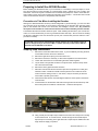
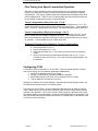
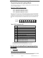
The AN12A0 is a plug and play DCC decoder designed to fit a number of Atlas N scale locomotives, including the B23-7, B30-7, B36-7, C628, C630, Dash 8-32BW, Dash 8-40B, Dash 8-40BW, Dash 8-40C, Dash 8-40CW, GP-38, GP38-2, DCC-ready GP-40, GP-40-2, DCC-ready SD-7, DCC-ready SD-9, SD-35, Train Master, and U25B locomotives. It replaces the LE063XF decoder and provides a number of additional features including: Silent Running®* motor drive, Torque Compensation for improved low speed performance, Simplified three point (CV2, CV6, and CV5) speed curves, Four Function Outputs (each with fifteen possible lighting effects), Operations Mode programming of all CVs, including addresses, and Selectable control of functions from the consist address. This is an EPF (extended packet format) decoder offering the following features (with Decoder Firmware Version 3.6) ∗ Silent RunningTM motor drive ∗ Torque Compensation for ultra smooth low speed performance ∗ Programmable Start, Mid and Maximum speed CVs that work in all speed modes ∗ Four function outputs with lighting effects generators that allow you to select from 15 different lighting behaviors (Ditch lights, Mars light, strobes, beacon, flicker, etc) ∗ Lighting outputs can be mapped to different DCC functions ∗ Uploadable speed table interpolated to 128 speed steps ∗ Advanced (decoder-assisted) consisting ∗ User selection of functions active in consist mode ∗ Support for all forms of DCC programming described in NMRA RP-9.2.3 ∗ Both short and long addresses can be programmed on main line (Ops Mode) ∗ Decoder programming lock mechanism allows independent programming of two decoders installed in the same locomotive ∗ Motor rating: 1 Amp peak (stall) ∗ Dimensions: 2.65 x 0.370 x 0.120 inches AN12A0 Four-Function DCC Decoder for Atlas N Scale Locomotives Item # 518299 Revised: 7/2/2009 * Silent Running is a registered trademark of NCE Corporation Locomotive decoder AN12A0 2 Preparing to Install the AN12A0 Decoder Before installing the AN12A0 decoder in your locomotive, it is necessary to test (and adjust, if necessary) the locomotive for proper operation on conventional DC power. Replace any worn out parts, such as brushes. Also clean any dirt or oxidation from the wheels and pickups to in order to insure that electrical contact is good. Now is also a good time to lubricate your locomotive. A locomotive that runs well under conventional DC will also run exceptionally well under DCC. Precautions to Take When Installing the Decoder: Although the AN12A0 decoder has many internal safeguards to prevent damage, you must not allow any metal part of the locomotive to touch surface components of the decoder other than the pickup pads on the decoder that connect to the wheel-sets, the headlights, and the motor. Any contact to other parts of the decoder can cause a direct internal short circuit and destroy the DCC decoder. The AN12A0 decoder has sensitive electronic parts. When installing this decoder in your N scale locomotive, it is recommended that you wear a grounded anti-static wrist strap. Also be careful in handling the decoder, especially in the area around the top rear part of the decoder (the area where the microprocessor is located). The AN12A0 comes with two LED headlights already installed. The light outputs of this decoder are designed only to drive these LEDs. The Atlas warranty is void if these LEDs are removed from the AN12A0 circuit board. Step by Step Installation: 1. Remove the locomotive shell from the frame. If you have difficulty removing the shell, 2. 3. 4. 5. 6. 7. 8. 9. contact Atlas customer service for assistance. Remove the light shroud (if any) at the front of the loco. Remove the fuel tank, if necessary, to allow future separation of the frame halves Loosen and remove the two screws holding the frame halves together. Lay the frame in its right side as shown in the photo below. Remove the top frame half. Place the trucks aside. Remove the factory light board from the frame. Determine if the decoder fits into the frame clips with enough friction to make good electrical contact. A small bit of solder has been placed on the contacts of the decoder to assist in making contact. In rare cases, it may be necessary to add a bit more solder to provide good contact. Orient the decoder with the motor tabs aligned with their contact pads on the bottom of the decoder. Fit the decoder into the left frame half while ensuring that the motor tabs line up with their contact pads on the bottom of the decoder. Tweezers will help here. 10. Using a small piece of Kapton tape, insulate the left motor tab to keep it from shorting to the left frame half. In a similar manner, insulate the right motor tab with Kapton tape to keep it from shorting to the right frame half. Kapton tape is available from the larger electronic supply companies. 7/2/2009 Page 2 Atlas Model Railroad Co., Inc Locomotive decoder AN12A0 3 11. Ensure that the two frame insulators are in place at each end of the frame. If the analog board used Atlas #480030 PCB Contact Clips, reinstall these clips on the AN12A0 decoder’s PC board. Then reinstall the right frame half and trucks. 12. Make sure that you have everything aligned correctly and that the trucks rotate freely. Then reinstall the two frame screws. Sometimes the trucks will not stay in position until you tighten the frame screws. 13. Carefully check to make sure that the motor contact strips are not touching either half of the frame. It is necessary to look down from the top through the frame cutouts in order to check for such unwanted shorts. There must be NO electrical contact between the motor contacts and any part of the frame. 14. Test run the locomotive (see below) before replacing the light shroud and body shell. Before test running your newly converted locomotive on full power, double check your wiring to make sure the motor is fully isolated and that there are no pinched or broken wires. We see many decoders returned due to wires getting pinched between the body shell and frame causing shorts. Always test your decoder installation on a current-limited programming track before you try it on full track power. If you have a Digitrax or MRC system that does not provide a current-limited programming track, use a 100 Ohm resistor in series with one of the track leads and listen for the "click" that verifies correct operation as you program the decoder. If you cannot read the CV values on the program track, do NOT operate the locomotive on DC or DCC until you have corrected the problem with reading CV s. We recommend that the first "full power" testing be done on regular DC. If the pickup polarity is reversed, you will want to correct this for proper analog mode operation. The decoders should be driven by a good quality smooth DC power unit. Power packs with pulse power systems such as "tracking control", etc. will give unpredictable operation. Analog operation is included in this decoder so you will be able to run on conventional layouts without having to remove the decoder or rewire your locomotive. Programming the AN12A0 Decoder The AN12A0 decoder supports all forms of both service mode (programming on an isolated programming track) and operations mode programming (programming on the main line). Using any of these programming methods, many features (such as the locomotive's address, acceleration, and configuration) can be customized to the individual locomotive in which the decoder is installed. These customized properties will be saved in non-volatile memory locations on the decoder so that they will retain their values even after power has been removed. All parameter values are set electronically, which means that the locomotive does not need to be opened again after the decoder has been installed in order to read or modify the values of these so-called Configuration Variables (CVs). The AN12A0 decoder has a total of 128 CVs. Not all of them are used at this time because many have been reserved for future use. Any NMRA-compliant DCC Command Station can be used to program the AN12A0 decoder. With several entry-level systems, only CV #1 (the locomotive address) can be set unless you use a separate DCC programmer. More advanced DCC systems support the ability to set many more CVs. The AN12A0 decoder supports all programming modes and can be programmed by all NMRA-compliant DCC systems. Note that the locomotive’s 2- and 4-digit addresses in CV1, CV17, and CV18 may be programmed in operations mode. However, resetting (writing 2 to CV30) can only be done on the program track and cannot be done on the main line. Instructions for reading and writing CVs are given in the user manual of your DCC system. Unlike earlier Atlas decoders, it is not necessary to power-cycle (turn power off and then on again) the AN12A0 decoder after writing to a CV. [However, resetting the decoder (setting CV30 = 2) does require moving the locomotive from the program track to the main line or power cycling in some other way.) 7/2/2009 Page 3 Atlas Model Railroad Co., Inc Locomotive decoder AN12A0 4 Configuration Variables and their Definitions The AN12A0 decoder supports a full range of features, which are activated by setting Configuration Variables. All CVs are numbered. These numbers are used during programming and are identical for all decoders that conform to NMRA standards, regardless of the decoder manufacturer. The following table lists the CVs supported in the AN12A0 decoder. Both CV numbers and Register numbers are provided for cross-reference. Some CVs (such as CV29) have specific meanings for each bit. In order to conform to the NMRA convention for bit numbering, the CV bit assignments shown in this table use the bit-numbering scheme of 0 to 7. Table 1: Configuration Variables (CVs) for the AN12A0 Decoder CV Description Range Default Value 1 Short address: This is the number that you enter into your DCC system to tell it the locomotive you wish to run with a short (2-digit) address. Start voltage: This is the voltage applied to the motor in speed step 1. Set this value so that the locomotive just starts moving at speed step 1. Acceleration Momentum: Determines the rate of change of speed upon acceleration. A higher value leads to a slower acceleration. Deceleration Momentum: Determines the rate of change of speed upon deceleration. A higher value leads to a slower deceleration. Vmax: Speed at highest speed step; 0=use default speed of 255 Vmid: Speed (on a scale of 1-255) at speed step 14 or 63; 0 = use default speed of 127 Version Number: This location stores the version number of the decoder. The value 36 for this decoder means firmware version 3.6. This CV is readonly. Manufacturers Identification: This value is the manufacturer ID of the decoder (Atlas=127). Packet Time-Out Value: (in ½ second increments) Time the decoder will wait before braking to a stop after running into a section of track with DC power. 0=Don’t brake Decoder Programming Lock “KEY”: This CV is always programmable even when “locked” Decoder Programming Lock ID: When CV15 = CV16, programming is unlocked, and the decoder will respond to programming commands. If CV15 is not equal to CV16 then decoder programming is locked, and it will not program (except CV15) or read. High Byte of Long (4 digit) Address: − Bits 0-5 are upper 6 bits of address − Bits 6,7 always = 1 Low Byte of Long (4 digit) Address Advanced Consist Address: Value 0 or 128 = no consist active Use of bits - Bits 0-6 short consist address (1-127 valid) - Bit 7 0 = direction is normal; 1 = direction is reversed Functions Active in Consist Mode: Bit 0 controls F1, bit 1 controls F2, bit 2 controls F3, etc. For each bit: - Bit value = 1 means function can be controlled at consist address; - Bit value = 0 means no consist control 1-127 3 0-100 0 1-255 0 1-255 0 1-255 0 1-255 0 2 3 4 5 6 7 8 11 15 16 17 18 19 21 7/2/2009 Page 4 36 127 1-255? 0 0 0 192 0 0 255 Atlas Model Railroad Co., Inc Locomotive decoder AN12A0 5 CV Description 22 Functions Active in Consist Mode: Bits 0, 1 control FL(f) and FL(r), respectively. For each bit: - Bit value = 1 means function can be controlled at consist address; - Bit value = 0 means no consist control Acceleration Adjust: This CV contains additional acceleration rate information that will be added to (or subtracted from) the base value contained in CV3. Deceleration Adjust: This CV contains additional deceleration rate information that will be added to (or subtracted from) the base value contained in CV4. 23 24 29 Range Decoder Configuration: A number of important decoder properties are set with CV29. Changes in CV29 can be done by adding together the decimal values (shown in parenthesis) for all the desired features and then writing the total into CV29. For an example, see the section titled Converting Binary Values of Individual Bits within a Configuration Variable into the Equivalent Decimal Value of the Entire CV. The definitions for the individual bits of CV29 are given below. Bit 0 0 = direction of operation is normal; 63 0 0 0-55 6 0,1 0 (1) 1 (2) 1 (4) 1 = direction of operation is reversed. Bit 1 Bit 2 only) 0 = 14 speed step mode (not supported) 1 = 28 or 128 speed step mode (always enabled) 0 = analog operation mode disabled (operates on DCC 1 0,1 1 = analog operation mode enabled 0 = use speed table defined by CV2, CV6, and CV5; 1 = use alternate speed table (CV67 to CV94). Bit 5 0 = use the short address in CV1; 1 = use the long address in CV17 and CV18 Bits 3, 6, and 7 are ignored by the decoder. Bit 4 30 Default Value 0,1 0,1 0 (16) 0 (32) Decoder Reset: While on the programming track, set CV30 to 2; the decoder will then reset to its factory-default settings, but only after you cycle power first off and then on again. You can do the power cycling by (1) tipping the locomotive to one side so that all the wheels on the other side are off the track, (2) holding it in this tipped position for 5 or 10 seconds, and (3) carefully lowering the locomotive back down so that all wheels are again on the track. You cannot reset this decoder on the main line. 33 34 35 36 37 38 39 40 Mappings: Decoder Output to DCC Function Output(s) controlled by FL(f) or F0 Output(s) controlled by FL(r) or F0 Output(s) controlled by F1 Output(s) controlled by F2 Output(s) controlled by F3 Output(s) controlled by F4 Output(s) controlled by F5 Output(s) controlled by F6 1 2 0 12 0 0 0 0 67 68 69 70 71 72 73 74 75 76 77 78 Step Sizes for Alternate Speed Table Alternate speed table step 1 Alternate speed table step 2 Alternate speed table step 3 Alternate speed table step 4 Alternate speed table step 5 Alternate speed table step 6 Alternate speed table step 7 Alternate speed table step 8 Alternate speed table step 9 Alternate speed table step 10 Alternate speed table step 11 Alternate speed table step 12 0 0 0 0 0 0 0 0 0 0 0 0 7/2/2009 Page 5 Atlas Model Railroad Co., Inc Locomotive decoder AN12A0 CV 6 Description Range Default Value 79 80 81 82 83 84 85 86 87 88 89 90 91 92 93 94 Alternate speed table step 13 Alternate speed table step 14 Alternate speed table step 15 Alternate speed table step 16 Alternate speed table step 17 Alternate speed table step 18 Alternate speed table step 19 Alternate speed table step 20 Alternate speed table step 21 Alternate speed table step 22 Alternate speed table step 23 Alternate speed table step 24 Alternate speed table step 25 Alternate speed table step 26 Alternate speed table step 27 Alternate speed table step 28 0 0 0 0 0 0 0 0 0 0 0 0 0 0 0 0 95 Reverse trim 0 116 Torque Kick Rate; The number of 16 ms periods in a row that the motor is ‘kicked’ with a voltage pulse Torque Kick Strength; How much voltage is used to kick the motor at slow speeds. Reduces to 0 as speed is increased. 117 118 120 121 122 123 0-6 0 0-50 0 Ditch Light Hold Time: Ditch light hold time (in ¼ second increments) after F2 goes off. Output 1 EFX generator Output 2 EFX generator Output 3 EFX generator Output 4 EFX generator 14 01 02 0 0 CV NOTES: 1. This decoder supports all DCC programming methods, including programming of addresses on the main line (Ops Mode programming). 2. It is suggested that you keep a log of all the CV values that you have programmed into the decoder. This step is not necessary if you use Decoder Pro or other decoder programming software that keeps track of all the changes in CV values that you have made. 3. If you accidentally change one or more CVs and your locomotive no longer operates correctly, the fastest way to recover may be to reset the decoder to its default values using CV30. (For details, please read the description of CV30 above.) Programming the Address The AN12A0 decoder comes pre-programmed to use the short address “3.” This address is the first thing that many people wish to change so that each of their locomotives has its own unique address. Most modern DCC systems handle automatically programming of both short (CV1 and CV29) and long (CV17, CV18, and CV29) addresses. There are a few DCC systems (such as the Lenz SET01, SET02 and some other entry-level systems) that require the user to compute the values of CV17 and CV18 when programming a long address. The following formulas may be used to compute these values. A. B. D. Divide the desired long address by 256 CV17 = the sum of 192 and the whole number part of the quotient you just calculated in Step A. Multiply the whole number part of the quotient you calculated in Step A by 256 CV18 = (the desired long address) - (the result of the calculation in step C) E. CV29 = 34 if analog mode disabled, 38 if analog mode enabled C. 7/2/2009 Page 6 Atlas Model Railroad Co., Inc Locomotive decoder AN12A0 7 Fine-Tuning Low Speed Locomotive Operation The factory settings normally provide good performance for most N-scale locomotives. However, you may want to improve or fine tune performance by adjusting the starting characteristics. This section explains what kinds of adjustments are possible and how to make the adjustments. There are two CVs that regulate how often and how hard the motor gets kicked at slow speeds to keep it turning smoothly. Torque Compensation (dither) kick rate - CV116: Is how frequently the motor is ‘kicked’ at slow speed. Typical adjustment is 2 to 4. The smaller the number the more often the motor gets a brief voltage ‘kick’. Factory default is 0 (off). A value of 1 applies kicks continuously. The maximum practical value is about 6. Torque Compensation (dither) kick strength - CV117: Is how hard the motor is ‘kicked’ at slow speeds. Typical adjustment is 4 to 25. The larger the number the more voltage is applied in each ‘kick’. The strength of these kicks fade out ratiometrically as speed is increased providing a smooth transition to normal motor operation. Factory default is 0 (off), usable range 0-50. Suggested Procedure for Adjusting Torque Compensation 1. 2. 3. 4. Set the Start Voltage CV2 = 0 Set the Kick Rate CV116 = 4 Set the Kick Depth CV117 = 20 Adjust the Kick Depth CV117 (up or down) until the locomotive just barely crawls. 5. Once you achieve fairly good low speed operation with CV116 = 4, try increasing the value of CV116 by 1 or 2 to see if the slow speed operation can be improved. Configuring CV29 CV29 may be the most important CV in all of DCC. With the AN12A0 decoder, CV29 allows you to change up to four different parameters independently 1. Direction of operation (normal or reversed) 2. Analog (conventional DC) operation (enabled or disabled) 3. Speed table [3-point (CV2, CV6, CV5) or 28-point (CV67 to CV94)] 4. Type of address to be used (short or long) Although CV29 allows one to select between 14 speed steps and 28/128 speed steps, the AN12A0 decoder always uses 28 or 128 speed steps. The listing for CV29 in Table 1 gives the parameters that can be set by each bit of CV29. Table 2 (below) gives some of the more commonly used values for CV29 and the features that each value provides. If none of the values in Table 2 gives you the features you want, the following section (Converting Binary Values of Individual Bits within a Configuration Variable into the Equivalent Decimal Value of the Entire CV) explains how to calculate the value of CV29 for any set of features. 7/2/2009 Page 7 Atlas Model Railroad Co., Inc Locomotive decoder AN12A0 8 Table 2: Commonly Used Values for CV29 Decimal Value for CV29 Long/Short Address Uploadable or Factory Speed Table Analog (DC) Operation Speed Mode 0 6 18 22 34 38 50 54 Short Short Short Short Long Long Long Long Factory Factory Uploadable Uploadable Factory Factory Uploadable Uploadable no yes no yes no yes no yes 28/128 28/128 28/128 28/128 28/128 28/128 28/128 28/128 Notes: yIf you want to reverse the direction of travel on DCC, increase the value for CV29 by one. (This change also reverses all directional lighting). yIf you want to reverse the DC direction, reverse the track pickup wires Unless you plan to operate your locomotive on both DC and DCC, Atlas recommends that you turn off DC operation by subtracting 4 from the current value of CV29. Turning off DC operation reduces the chance of a pulse on the track making the DCC decoder think there is DC power on the track and then behaving strangely. Converting Binary Values of Individual Bits in a Configuration Variable into the Equivalent Decimal Value of the Entire CV Reasons for Setting and Clearing the Individual Bits of a Configuration Variable In order to make a DCC decoder perform in the manner that you wish it to perform, one must sometimes set or clear individual bits of a CV. CV21, CV22, and CV29 are examples of CVs that require you to set or clear individual bits. To program a DCC decoder using a DCC system that allows the writing of only decimal values into CVs, it is first necessary to convert the values of all the individual bits of that CV that are to be set to the binary value 1 into their equivalent decimal values. It is then necessary to add together all of these equivalent decimal values. Procedure for Converting Individual CV Bit Values into a Decimal Equivalent Value for the CV Table 3 illustrates how to calculate the decimal value that must be written into a CV in order to set and/or clear a specified set of individual bits within that CV. Table 3: Calculation of Equivalent Decimal Value of a CV Each bit of a CV that is to be set to the binary value “1” can be represented by the equivalent decimal number shown in the second column of this table. To determine the equivalent decimal value to be written into the CV, first write in column 3 of this table the decimal equivalent values of all the bits of the CV that are to be set to a binary 1. Write nothing in column 3 for each bit of the CV that is to be cleared, i.e., set to a binary 0. Then add up all the numbers that you have written in column 3. The sum that you get is the equivalent decimal value you need to write into the CV. Bit Number Decimal Equivalent 0 1 2 3 4 5 6 7 1 2 4 8 16 32 64 128 Decimal Values for CV Calculation SUM: 7/2/2009 Page 8 Atlas Model Railroad Co., Inc Locomotive decoder AN12A0 9 Table 4: Example - Calculating the Default Value for CV29 From the definition of CV29 given in Table 1, we see that the default values of bits 1 and 2 are binary 1s; whereas, all other bits in CV29 have a default value of binary 0. In order to compute the decimal equivalent default value of CV29, simply write in the rightmost column of this table the number "2" for bit 1 and the number "4" for bit 2. Then add up all the non-zero numbers that you have entered into this rightmost column. Since the sum of these numbers is 6, the decimal number to be programmed into CV29 is 6. Bit Number Decimal Equivalent 0 1 2 3 4 5 6 7 1 2 4 8 16 32 64 128 Decimal Values for CV Calculation SUM: 2 4 6 Setting Locomotive Speed Characteristics If two locomotives are run together in a consist, it is important that both locomotives travel at the same speeds for each DCC throttle setting. If there is a significant speed mis-match, there will be excess wear on the locomotives’ mechanisms. There are two ways to set the locomotives’ speed characteristics. Establish a three point speed curve using CV2 = Vstart, CV6 = Vmid, and CV5 = Vmax Establish a 28-point alternate speed curve using C67 to CV94 Using Three Point Speed Curves There are 4 CVs that define: • • • • The voltage at which the motor starts The maximum motor speed The mid speed range response characteristics or ‘speed curve’. Compensation for a motor that runs faster in one direction Start Voltage - CV2 (Vstart): This is the amount of voltage sent to the motor when first starting up. We set CV2 so the locomotive is almost able to maintain movement at speed step 1. We use CV116 and 117 to apply enough torque compensation to keep it turning on speed step 1. Typical values for CV2 are in the range of 0-35. Vmid - CV6: CV6 determines how the motor responds to advancement of the throttle through its middle speed ranges. If you set CV6 lower than half the maximum speed you’ll have smaller increases in motor speed through the lower speed ranges. Then, as you hit the upper speed ranges there will be larger increases between speed steps. In the diagram below you can see this best illustrated by the ‘customized’ line. If you set Vstart larger than 0 you will most likely want to raise Vmid so a reasonable slope is maintained in the ‘speed curve’. If CV6 is set to 0 the decoder will use 127 as the value. If you use high values in CV117 you will want to increase CV6 by a proportional amount to keep a smooth acceleration curve. Vmax - CV5: If your locomotive runs too fast you can use CV5 to lower its maximum speed. Setting CV5 to 255 uses the maximum possible voltage to run the motor when full speed is requested. Set CV5 to a smaller value to reduce the top speed. A value of 128 will yield approximately ½ full voltage to the motor at top speed. 192 will provide about ¾ full voltage. All speeds from the middle speed step to the maximum will be proportionally reduced (see diagram). If CV5 is set to 0 the decoder will use 255 for maximum speed. Always make sure CV5 is greater than CV6 to avoid erratic operation. 7/2/2009 Page 9 Atlas Model Railroad Co., Inc Locomotive decoder AN12A0 10 Vmid - CV6: CV6 determines how the motor responds to advancement of the throttle through its middle speed ranges. If you set CV6 lower than half the maximum speed you’ll have smaller increases in motor speed through the lower speed ranges. Then, as you hit the upper speed ranges there will be larger increases between speed steps. In the diagram below you can see this best illustrated by the ‘customized’ line. If you set Vstart larger than 0 you will most likely want to raise Vmid so a reasonable slope is maintained in the ‘speed curve’. If CV6 is set to 0 the decoder will use 127 as the value. If you use high values in CV117 you will want to increase CV6 by a proportional amount to keep a smooth acceleration curve. Reverse trim (also forward trim) - CV95: Values from 1-127 make decoder run faster in reverse than forward. 1 is one speed step faster in reverse, 2 is two steps faster, etc. Values from 129-255 make decoder run faster in forward than reverse. 129 is one speed step faster in forward, 130 is 2 speed steps faster, etc. The values 0 and 128 add nothing to either direction. 255 factory default 192 Vmax Voltage 128 customized Vmid 064 Vstart Motor 'Speed Curve' 000 1 32 64 96 128 Speed steps Example of Three-Point Speed Curve Creating a 28-Point Alternate Speed Curve Common reasons for specifying an alternate speed curve for a DCC-equipped locomotive are to: (1) Insure that dissimilar locomotives have the same performance characteristics (2) Have model locomotives perform more prototypically. In this example of creating an alternate speed curve, we will assume that the AN12A0 decoder has been properly installed and tested. We also assume that you are familiar with the general process of programming CVs using your DCC system. The first step in creating an alternate (non-default) speed curve is to assign a value to each internal speed step. This assignment is done by specifying a value for each of the CVs from CV67 to CV94 using a table such as that below, but substituting your desired speed step settings for the default CV values given in the Speed Step in 28 Step Mode column of this table. The second step in creating an alternate speed curve is to write each value listed in the Desired Speed Step Value column into the CV corresponding to that speed step. The third and final step is to activate your alternate speed curve by writing the binary value “1” into bit 4 of CV29 (i.e., CV29.4 =1). Unless this bit in CV29 has been set to a binary 1, the default speed curve that was preset into the decoder at the factory will be used. 7/2/2009 Page 10 Atlas Model Railroad Co., Inc Locomotive decoder AN12A0 11 Table 5: Default Speed Steps for AN12A0 Decoder Speed Step in 28 Step Mode 1 2 3 4 5 6 7 8 9 10 11 12 13 14 15 16 17 18 19 20 21 22 23 24 25 26 27 28 CV # 67 68 69 70 71 72 73 74 75 76 77 78 79 80 81 82 83 84 85 86 87 88 89 90 91 92 93 94 Desired Speed Step Value In order to calculate the correct speed-step value for the 128 speed-step mode, the AN12A0 decoder will internally average the values for 28 speed steps that were specified in (CVs 67 to 94). 7/2/2009 Page 11 Atlas Model Railroad Co., Inc Locomotive decoder AN12A0 12 Programming Special Lighting Effects The AN12A0 decoder allows you to configure the lighting behavior of each function output to any of 15 different behaviors. Description of EFX Configuration CVs CV120 - Lighting effect configuration for output 1 CV121 - Lighting effect configuration for output 2 CV122 - Lighting effect configuration for output 3 CV123 - Lighting effect configuration for output 4 Each output wire can select from 15 different lighting effects by using its associated EFX configuration CV. Pick the value for the CV from the table below, add 1 or 2 if you want the effect to be directional (footnotes 2 and 3), then add 128 if you are using a white LED for the effect. Ditch lights should not be made directional; they’re not directional in real life. bit weight bit name 128 1 LED 64 --- 32 16 8 Effect configuration 4 2 1 2 REV FWD3 Table 6: EFX Configuration CVs Value for CV 0 4 8 12 16 20 24 28 32 36 40 44 48 52 56 60 Description of Lighting Effect Standard on/off function output Firebox flicker (brighter when accelerating) Mars light Rotary Beacon Gyrolight Double Strobe Strobe A Strobe B (alternates with Strobe A) Dim when F0 and F4 on, otherwise bright Dim when F0 and F8 on, otherwise bright Dim in forward, bright in reverse Dim in reverse, bright in forward Type 2 Right Ditch light, effect on if F2 on, output off otherwise Type 2 Left Ditch light, effect on if F2 on, output off otherwise Type 1 Right Ditch light, effect on if F0 and F2 on, bright if F0 on and F2 off, off if F0 off Type 1 Left Ditch light, effect if F2 and F0 on, bright if F0 on and F2 off, off if F0 off 1 - Functions are designed to use 12–16 volt, 30-40 ma incandescent lamps. If you are using a white LED (with 1K limiting resistor) add 128 to the CV value. 2 - If you want the function to be active only in the reverse direction add 2 to the CV value. 3 - If you want the function to be active only in the forward direction add 1 to the CV value. Four Examples of Lighting Effects Programming and Function Mapping 1. Ditch Lights Ditch Light Hardware Considerations For operating ditch lights, the LEDs used for the ditch lights must be connected to Lighting Outputs 3 and 4 on the decoder and also to the Common (+VE) terminals. 7/2/2009 Page 12 Atlas Model Railroad Co., Inc Locomotive decoder AN12A0 13 If your locomotive has factory-installed ditch lights, Outputs 3 and 4 and the Common terminals will already be connected to the ditch light LEDs. If your locomotive does not have factory-installed ditch lights, you will have to make these connections yourself. The connections to lighting Outputs 3 and 4 and Common are shown below in the photograph of the bottom of an AN12A0 decoder. Warning: Do not attempt to solder to the Output 3 and Output 4 connections on this decoder unless you have the proper equipment and also have experience working with circuit boards that have many closely-spaced parts. Ditch Light Programming Considerations If you do nothing to modify the CVs of a decoder-equipped Atlas N-scale Dash 8-40CW locomotive, the ditch lights will still operate as follows: F2 off: Ditch lights off F2 on: Ditch lights on steadily Ditch lights not directional (on in either direction) However, if you write the following values into CV122 and CV123 (The default value for both CVs is 0,) CV122 = 184 CV123 = 188 the ditch lights will have additional capabilities F1 off: Ditch lights off F1 on: Ditch lights on steadily or flashing alternately (depending on the state of F2) F2 off: Ditch lights on steadily F2 on: Ditch lights flashing alternately Ditch lights are directional Note: The ditch lights are directional (on only when loco is moving forward) Note: The ditch lights do not stop flashing instantly after F2 is turned off, but they will eventually return to the steady-on state. 2. Rule 17 Lighting Rule 17 refers to how the locomotive engineer operates the locomotive headlights during the running of the train. The rule varies from road to road but generally requires the dimming of the headlight(s) when in a siding waiting to meet another train, passing through passenger stations or moving within yard limits. What we want to do Use output 1 for the front Headlight with F0 used to turn the light on and off. Unless dimmed or turned off, the front Headlight is to be on bright in both directions of locomotive travel We want to be able dim the front Headlight using F4 Use output 2 for the rear Headlight with F3 used to turn the light on and off. Unless dimmed or turned off, the rear Headlight is to be on bright in both directions of locomotive travel 7/2/2009 Page 13 Atlas Model Railroad Co., Inc Locomotive decoder AN12A0 14 We want to be able dim the rear Headlight separately from the front Headlight by using F8 How to do it Output 1 is already activated by F0 (factory default setting of CV33 =1) Configure Output 1 as a standard output, on in both directions, yet dimmable when F4 is activated. Set CV120 to 32 Change Output 2 so that it is activated by F3 by setting CV34 to 16 and CV37 to 2 Configure Output 2 as a standard output, on in both directions, yet dimmable when F8 is activated. Set CV121 to 36 3. Mars Light What we want to do Use output 2 (yellow wire) for a Mars light. The Mars light is to be on in the forward direction only How to do it 4. Set Output 2 is to be activated by F1, set CV35 to 2 Make sure F0 no longer controls output 2, set CV34 to 0) Configure output 2 as a forward-only Mars light. Set CV121 to 9. We get the value of 9 by using 8 (Mars Light) plus 1 (output operates only in forward direction) Switcher What we want to do Headlights that dim in the opposite direction that the locomotive is traveling Use output 1 as Headlight and output 2 as Rear light How to do it Outputs 1 and 2 are already activated by F0 due to the factory default settings. Configure output 1 as bright in forward dim in reverse. Set CV120 to 44 Configure output 2 as bright in reverse dim in forward. Set CV121 to 40 7/2/2009 Page 14 Atlas Model Railroad Co., Inc Locomotive decoder AN12A0 15 Troubleshooting Decoder Programming Problems Fault Cause and Solution Locomotive does not move when you address it on DCC system. Locomotive does not move when DCC system is set to the address in CV1, even though this address can be read from CV1. Locomotive does not move when DCC system is set to the short address in CV1. The short address can be read from CV1, and DCC functions can be activated when the DCC system is set to the address in CV1. Check to see if you have selected the correct address for that locomotive. DCC functions can be activated when DCC system is set to the locomotive address, but the locomotive does not move. The locomotive does not appear to be using the customized speed curve values that you have entered into CVs 67 to 94. Function 0 (lighting) cannot be switched on and off. Decoder is set to use a customized speed curve (CV29.4 = 1), but you entered zero values into CVs 67 to 94. Either clear bit 4 of CV29 or else enter suitable non-zero speed step values into CVs 67 to 94. Locomotive headlights are only illuminated when the locomotive speed is increased or decreased; the locomotive headlights go on and off as the locomotive speed changes. 7/2/2009 You have entered the short address (CV1), but the decoder is set to use the long address, i.e., bit 5 of CV29 has been set. Use the long address or else clear bit 5 of CV 29. Check whether to see if an advanced consist address has been programmed into CV19, i.e., check to see whether or not CV19 has a value greater than 0. If CV19 has a non-zero value, you must either use this advanced consist address to operate the locomotive or else program the value 0 into CV19. Bit 4 is not set to “1” in CV29. Matching of speed steps is incorrect: The decoder has been set to 28/128 speed steps, but the DCC system has been set to 14/27 speed steps. Either set the DCC system to 28/128 speed steps or change the decoder speed step setting to 14/27 speed steps. (CV29.1 = 0). Matching of speed steps is incorrect: The decoder has been set to 14/27 speed steps, but the DCC system has been set to 28/128 speed steps. Either set the DCC system to 14/27 speed steps or change the decoder speed step setting to 28/128 speed steps. (CV29.1 = 1). Page 15 Atlas Model Railroad Co., Inc Locomotive decoder AN12A0 16 Atlas Limited One-Year DCC Decoder Warranty Please fill out and mail the Warranty card, within 30 days of purchase. Atlas Model Railroad Company, Inc. warrants that this decoder will be free from defects in material and workmanship for a period of one year from the date of purchase. If this decoder fails during the warranty period, uninstall and carefully pack the item in the original carton, together with the dated sales receipt, and return to: Atlas Model Railroad Company, Attention HO/N Repair, 378 Florence Avenue, Hillside, NJ 07205. Defects due to misuse, improper maintenance and/or abuse are not covered by the warranty. This warranty gives you specific legal rights and you may also have other rights, which vary from state to state. For Technical Assistance www.atlasrr.com [email protected] This equipment complies with Part 15 of FCC Rules. Operation is subject to the following two conditions: (1) this device may not cause harmful interference, and (2) this device must accept any interference received, including interference that may cause undesired operation. Please save this manual for future reference. NCE Corporation designed the AN12A0 decoder for Atlas Model Railroad Co., Inc. The decoder may be manufactured either by NCE or by Atlas. © 2009 Atlas Model Railroad Co, Inc; All Rights Reserved. 7/2/2009 Page 16 Atlas Model Railroad Co., Inc


![TR4W User Manual [English Version]](http://vs1.manualzilla.com/store/data/005728234_1-e27c4fea1c6d513d6e0fdc1451ef66f1-150x150.png)