1
Analytical Balance
BM-20
BM-22
BM-252
BM-200
BM-300
BM-500
1WMPD4002195A
© 2010 A&D Company Ltd. All rights reserved.
No part of this publication may be reproduced, transmitted, transcribed, or translated into any language in
any form by any means without the written permission of A&D Company Ltd.
The contents of this manual and the specifications of the instrument covered by this manual are subject
to change for improvement without notice.
Windows, Word and Excel are registered trademarks of the Microsoft Corporation.
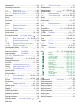
Contents
Basic Operation
1.
Introduction.............................................................................................................................. 3
1.1.
Features............................................................................................................................... 4
1.2.
Compliance.......................................................................................................................... 5
2.
Unpacking The Balance.......................................................................................................... 6
3.
Installing The Balance And Precautions ................................................................................. 8
Installing The Balance ......................................................................................................... 8
Precautions Before Use (Environmental Condition And Preparations) ............................ 10
Cautions During Use (For Precision Weighing) ................................................................ 11
Cautions After Use (Management Of The Balance) ......................................................... 12
Cautions For Power Supply............................................................................................... 12
3.1.
3.2.
3.3.
3.4.
3.5.
4.
Display Symbols And Key Operation.................................................................................... 13
5.
5.1.
5.2.
5.3.
Weighing Units ...................................................................................................................... 14
Units................................................................................................................................... 14
Storing Active Units............................................................................................................ 17
Selecting Unit And Weighing Mode................................................................................... 18
6.1.
6.2.
6.3.
6.4.
6.5.
6.6.
6.7.
Weighing................................................................................................................................ 20
Basic Operation (Gram Mode) .......................................................................................... 20
Smart Range For BM-22 ................................................................................................... 21
Counting Mode (PC).......................................................................................................... 22
Percent Mode (%).............................................................................................................. 24
Built-in DC Static Eliminator (Neutralization Device)......................................................... 25
Monitoring Clock and Environmental Sensors .................................................................. 27
Repeatability Test............................................................................................................... 28
6.
Adapting To The Environment
7.
Response Adjustment ........................................................................................................... 29
7.1.
Automatic Response Adjustment ...................................................................................... 29
7.2.
Manual Response Adjustment .......................................................................................... 30
8.
8.1.
8.2.
8.3.
8.4.
8.5.
8.6.
8.7.
Calibration (To Adjust The Weighing Value).......................................................................... 31
Calibration Group............................................................................................................... 31
Automatic Self Calibration (For variation of ambient temperature)................................... 32
One-Touch Calibration (For Common Use) ...................................................................... 32
Calibration Test Using the Internal Mass........................................................................... 33
Calibration Using An External Weight ............................................................................... 34
Calibration Test Using An External Weight........................................................................ 35
Correcting The Internal Mass Value .................................................................................. 36
9.1.
9.2.
Function Switch And Initialization.......................................................................................... 37
Permit Or Inhibit................................................................................................................. 37
Initializing The Balance...................................................................................................... 38
9.
Selecting Functions
10.
Function Table ....................................................................................................................... 39
10.1.
Setting The Function Table................................................................................................ 39
10.2.
Details Of The Function Table ........................................................................................... 41
10.3.
Description Of The Class "Environment, Display"............................................................. 43
BM series
1
10.4.
10.5.
10.6.
10.7.
Description Of The Item "Data Output Mode" ................................................................... 45
Description Of The Item "Data Format"............................................................................. 46
Data Format Examples...................................................................................................... 49
Clock And Calendar Function............................................................................................ 51
11.
ID Number And GLP Report ................................................................................................. 52
11.1.
Setting The ID Number...................................................................................................... 52
11.2.
GLP Report........................................................................................................................ 53
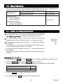
12.
Data Memory......................................................................................................................... 58
12.1.
Notes On Using Data Memory .......................................................................................... 58
12.2.
Data Memory For Weighing Data...................................................................................... 59
12.3.
Data Memory For Calibration And Calibration Test........................................................... 62
13.
Underhook............................................................................................................................. 63
14.
Density Measurement (Specific gravity) ............................................................................... 64
Interface And Communication
15.
Standard Input And Output Interface..................................................................................... 67
15.1.
RS-232C Interface............................................................................................................. 67
15.2.
Connection To Peripheral Equipment................................................................................ 68
15.3.
Commands ........................................................................................................................ 71
Maintenance
16.
Maintenance.......................................................................................................................... 76
16.1.
Treatment Of The Balance ................................................................................................ 76
16.2.
Error Codes ....................................................................................................................... 76
16.3.
Other Display ..................................................................................................................... 78
16.4.
Checking The Balance Performance And Environment ................................................... 79
16.5.
Asking For Repair .............................................................................................................. 79
17.
Specifications ........................................................................................................................ 80
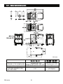
17.1.
External Dimensions.......................................................................................................... 81
17.2.
Options And Peripheral Equipment ................................................................................... 82
18.
Terms/Index........................................................................................................................... 86
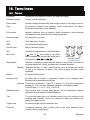
18.1.
Terms ................................................................................................................................. 86
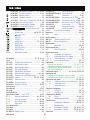
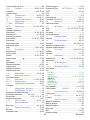
18.2.
Index .................................................................................................................................. 87
2
BM series
1.
Introduction
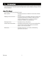
This manual describes how the BM series balances work and how to get the most out of them in
terms of performance. Read this manual thoroughly before using the balance and keep it at hand
for future reference.
About This Manual
This manual consists of the following five parts:
Basic operation .............................. Describes precautions, the balance's construction and basic
operation.
Adapting to the environment ........... Describes response (and stability) adjustment to adapt to the
environment where there is vibration or drafts, the way to
maintain weighing precision in a variation of ambient
temperature, calibration and calibration test.
Selecting functions .......................... Describes functions of the balance.
Interface and communication.......... Describes the serial interface used for communicating with a
computer that requests weighing data and controls the
balance, and for use with a printer
Maintenance .................................. Describes maintenance, error codes, troubleshooting,
specifications and options.
BM series
3
1.1. Features
A built-in DC static eliminator can eliminate static electricity from the weighing sample before the
measurement, reducing weighing error.
Each electrode unit of the eliminator is designed to be removed, cleaned and replaced.
Automatic self calibration, using the internal mass, adapting to changes to temperature changes.
Response adjustment adapting to drafts and/or vibration automatically.
Memory function to store weighing data and calibration data.
When only weighing data is stored, a maximum of 200 data can be stored.
Interval mode to store the weighing data periodically.
Good laboratory practice (GLP) data can be output using the RS-232C serial interface.
A built-in clock and calendar that can add the time and date to the output data.
Underhook, for measuring density and weighing magnetic materials.
Multiple weighing units with most of the common units used around the world.
Gram, Milligram, Counting mode, Percent mode, Ounce (Avoir), Troy Ounce, Metric carat, Momme,
Pennyweight, Grain (UK), Tael (preset in the factory), Tola (India), Messghal, Density mode
BM-22 is equipped with a smart range function to weigh with the precision range (a higher
resolution) when zeroing a tare weight within the weighing capacity.
The test tube holder is included in the accessories of BM-20 and BM-22.
Density mode for calculating the density of a solid.
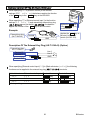
BM series balances are equipped with an RS-232C serial interface and a USB interface to
communicate with a computer. When printing data using the RS-232C interface, by using the USB
interface, the data can be transmitted to a computer at the same time. Communications between
the BM series balance using the RS-232C interface and a Windows computer using the Windows
communication tools software (WinCT) make building a system very easy.
Connecting the USB interface of the balance, by cable to a Windows computer, allows
transmission of the weighing data to Excel or Word.
When multiple balances have the BM-08 Ethernet interface installed in place of the USB interface
and connected to a LAN, data can be acquired from each of them using the WinCT-Plus software.
The weighing data can be stored by connecting the accessory data logger (AD-1688) directly,
when not using a computer.
4
BM series
1.2. Compliance
1.2.1.
Compliance With FCC Rules
Please note that this equipment generates, uses and can radiate radio frequency energy. This
equipment has been tested and has been found to comply with the limits of a Class A computing
device pursuant to Subpart J of Part 15 of FCC rules. These rules are designed to provide
reasonable protection against interference when equipment is operated in a commercial
environment. If this unit is operated in a residential area, it may cause some interference and
under these circumstances the user would be required to take, at his own expense, whatever
measures are necessary to eliminate the interference.
(FCC = Federal Communications Commission in the U.S.A.)
1.2.2.
Compliance With EMC Directives
This device features radio interference suppression and safety regulation in compliance
with the following Council Directives
Council directive 89/336/EEC
EN61326 EMC directive
Council directive 73/23/EEC
EN60950 Safety of Information Technology Equipment
The CE mark is an official mandatory European marking.
Please note that any electronic product must comply with local laws and regulations when sold or
used anywhere outside Europe.
BM series
5
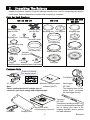
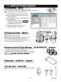
2.
Unpacking The Balance
Unpack the balance carefully. Keep the packing material to be used for transporting the balance
in the future. See the illustrations to confirm that everything is contained.
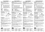
Parts For Each Products
BM-22, BM-20
Small weighing
pan for filter
Weighing pan
Large weighing
pan for filter
Weighing pan
Pan support
Pan support
Test tube holder
Weighing pan
Pan support
Fine range ring
Small fine range ring
Dust plate
BM-500, BM-300,
BM-200
BM-252
Fine range ring
Tweezers
AX-MX-36
Breeze break ring
φ15, 0.8
φ12, 0.3
φ8, 0.05
Large
Medium
Small
Round aluminum analytical pans (each 10 pieces)
Dust plate
Breeze break ring
Dust plate
Common Parts
Position of placing
AC adapter labels
D-sub 9pins
AC adapter
AC adapter labels Windows communication
Note
software (WinCT)
Please confirm that the AC adapter type is
correct for your local voltage and receptacle type.
USB cable
Display cover
Separation plate
If unnecessary, remove it.
6
Data logger
AD-1688
The weighing data can be
stored when connecting
the data logger directly.
Tweezers
AD-1689
Tweezers for handling a weight.
Use it to avoid temperature changes
due to having your hand in the
weighing chamber, thus to perform
accurate calibration.
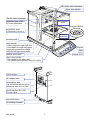
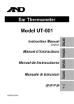
BM series
LED of the static eliminator
Glass door handle
The DC Static eliminator
Neutralization
area
Electrode units of the
DC static eliminator
Example of BM-20
Separation plate
If unnecessary, remove it.
Weighing
chamber
Leveling foot
Joint handle
When jointing the right (left) slide
door handle, the right (left) glass
door can be opened or closed
with the left (right) joint handle.
Display
Keys
Display cover
Bubble spirit level
Glass door handle
The handle for the glass door.
The handle can be joined to the joint handle
USB interface
AC adaptor jack
External key jack
Cap the terminal with accessory
rubber cap when it is not used.
Serial interface RS-232C
D-sub 9 pins
Anti theft device
Grounding terminal
BM series
7
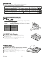
3.
Installing The Balance And Precautions
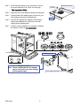
3.1. Installing The Balance
Step 1 Refer to "3.2. Precautions Before Use (Environmental Condition And Preparations)"
concerning the place to install the balance. Place the balance on a firm weighing table.
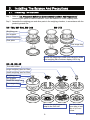
Step 2 Assemble the weighing pan and other parts in the weighing chamber, in accordance with the
product type and use.
BM-500, BM-300, BM-200
BM-252
Weighing pan
Pan support
Breeze break ring
Dust plate
Fine range ring
Use the fine range ring to avoid errors caused by drafts
when weighing with a minimum display of 0.01 mg.
BM-22, BM-20
Test tube holder
Large weighing pan for filter
Small weighing pan for filter
Weighing pan
Pan support
Small fine range ring
Fine range ring
Dust plate
Choose the weighing pan to
adapt to the filter size.
8
Use the holder for
micro tube or test
tube of φ12 mm
or less.
BM series
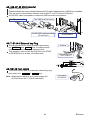
Step 3 If the separation plate is not necessary, remove
the screw and take it off. Refer to next page
"The Separation Plate".
Separation plate
Screw
Step 4 Adjust the level of the balance using the leveling feet.
Step 5 Confirm that the AC adaptor type is correct for your
local voltage and power receptacle type.
Hook
Step 6 Connect the specified AC adapter to the balance.
Warm up the balance for at least one hour with
nothing on the weighing pan.
Step 7 Confirm correct weighing. If necessary, calibrate
the balance. Refer to "8. Calibration".
BM-200, BM-300,
BM-500, BM-252
BM-252
BM-22, BM-20
Leveling foot
AC adaptor jack
Bubble spirit level
Example of outlet
Note Please confirm that the AC adapter
type is correct for your local voltage
and receptacle type.
BM series
Grounding terminal
9
The Separation Plate
Note: Take care that the separation plate is not broken when operating it.
Removing the Separation Plate
Step 1 Support the separation plate and
remove the screw from the plate.
Step 1
Screw
Hook
Step 2 Lift the plate and remove hooks.
Step 3 Rotate the plate on the axis of the back edge.
Rotate the plate on the axis of the front edge.
Step 3
Step 1
Step 2
Step 4 Remove the plate from the chamber.
Attaching the Separation Plate
Use the arrows in reverse to attach the plate.
Step 5 Insert the plate into the chamber. (Reversed Step 4)
Step 3
Step 6 Rotate the plate on the axis of the front edge.
Level the plate. (Reversed Step 3)
Step 4
Step 7 Insert hooks and hook the plate. (Reversed Step 2)
Step 8 Install and fix the screw. (Reversed Step 1)
Hook
Separation plate
3.2. Precautions Before Use (Environmental Condition And Preparations)
To ensure that you get the most from your balance, please try to follow these conditions as closely as
possible. Consider these conditions for BM-20 and BM-22 that are sensitive instrument specially.
The best operating temperature is about 20°C / 68°F at about 50% Relative Humidity.
The weighing room should be free of dust.
The weighing table should be solid and free from vibration, drafts (such as frequently opening
doors or windows) and as level as possible. We recommend to use the anti-vibration table
(AD-1670) and remote controller (AD-8922A) for BM-20 and BM-22.
Do not install the balance where it will be subject to vibration. Corners of rooms are best.
Do not install the balance near a heater, air conditioner, or in a breeze.
Do not install the balance in direct sunlight and excessive temperature changes.
Do not use the balance near other equipment which produces magnetic fields.
Adjust the level of the balance using the leveling feet.
Please warm-up the balance for at least one hour. Plug-in the AC adapter as usual.
Calibrate the balance before using and after moving it to another location.
Ensure a stable power source when using the AC adapter.
Do not place or use the balance where there is flammable or corrosive gas present.
10
BM series
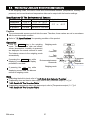
3.3. Cautions During Use (For Precision Weighing)
Note the following items to get accurate weighing data.
Charged material
Discharge static electricity from the weighing material. When
weighing sample (plastics, insulator, etc.) could have a static
charge, the weight value is influenced. Ground the balance, and
Eliminate the static electricity using the built-in static eliminator.
Try to keep the ambient humidity at or above 45%RH in the room.
Use a metal shield case.
Wipe a charged material (plastic sample etc.) with a damp cloth.
Metal case
This balance uses a strong magnet as part of the balance assembly,
so please use caution when weighing magnetic materials. If there is
a problem, use the underhook (on the bottom of the balance) to
suspend the material away from the influence of the magnet.
Eliminate temperature differences between the weighed sample and
the environment. When a sample is warmer (cooler) than the ambient
temperature, the sample will appear lighter (heavier) than the true
mass. This error is due to the rising (falling) draft next the sample. If
you touch the sample, the same type error will occur. Do not touch the
sample directly with your hand. Use tweezers or other tools.
Do not drop things upon the weighing pan, or place a weight
beyond the range of the balance on the weighing pan.
Grounding
Magnet material
Draft
20°C
40°C
Weighing pan
Shock
Make each weighing gently and quickly to avoid errors due to
changes in the environmental conditions.
We recommend that the fine range ring and separation plate are
used to avoid weighing error caused by drafts when BM-252 displays
a weighing value in unit of 0.01 mg (minimum display: 0.01 mg).
We recommend that the small fine range ring, fine range ring
and separation plate are used to avoid weighing error caused by
drafts when BM-22 and BM-20 display a weighing value in unit of
0.01 mg and 0.001 mg (minimum display: 0.01 mg and 0.001 mg).
Take into consideration the affect of air buoyancy on a sample
when more accuracy is required.
Do not use a sharp instrument (such as a pencil or ball point pen) to
press the keys, use your finger only.
Press the RE-ZERO key before each weighing to prevent possible
errors.
Avoid foreign matter (dust, liquid or metal fragments) that could get
inside the balance.
Operate your balance gently. Shorten the operation time as much
as possible (Opening and closing door, putting and removing
sample). Use a pair of tweezers to avoid temperature changes due
to heat from inserting your hand into the weighing chamber.
BM series
11
Fine range ring
BM-252
Small fine range ring
Fine range ring
BM-20
BM-22
3.4. Cautions After Use (Management Of The Balance)
Avoid mechanical shock to your balance.
Do not disassemble the balance. Contact your local A&D dealer if your balance needs service
or repair.
Do not use solvents to clean the balance. For best cleaning, wipe with a dry lint free cloth or a
lint free cloth that is moistened with warm water and a mild detergent.
Avoid foreign matter (dust, liquid or metal fragments) that could get inside the balance.
3.5. Cautions For Power Supply
Do not remove the AC adapter while the internal mass is in motion, for example, right after the
AC adapter is connected, or during calibration using the internal mass.
If the AC adapter is removed under the conditions described above, the internal mass will be
left unsecured, that may cause mechanical damage when the balance is moved.
Before removing the AC adapter, confirm that zero is displayed in the weighing mode, then
press the ON:OFF key.
When the AC adapter is connected, the balance is in the standby mode if the standby indicator
is on. This is a normal state and does not harm the balance. For accurate weighing, we
recommend that you always plug in your balance so it can warm up.
Connect the AC adapter for BM-22 and BM-20 normally.
12
BM series
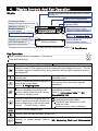
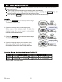
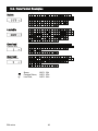
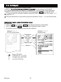
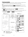
4.
Display Symbols And Key Operation
Display
The amount of stored data with data memory function
Humidity (%)
Response indicator for approx. 30
seconds when weighing starts.
Right and left glass door indicator
Air pressure (hPa)
Standby indicator of
interval memory function
Indicator of static eliminator
Processing indicator
Weighing in liquid of density mode
Stabilization indicator
Standby indicator
of power supply
Weighing data or stored data
The current data number
Weighing in air of density mode
Prior notice indicator of
automatic self calibration
Units.
Refer to "5. Weighing Units".
Blinking indicators
Active indicator of
interval memory function
The interval memory function is used to store periodical weighing data. Refer to "12. Data Memory".
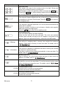
Key Operation
Press and release the key immediately or "Click the key" ..................................................................
Press and hold the key .......................................................................................................................
Key
When pressed and released
When pressed and held
The key to turn the display ON and OFF. The standby indicator is displayed when the
display is turned off. The weighing mode is enabled when the display is turned on. This key
is available anytime. Pressing the key during operation will interrupt the operation and turn
the display OFF.
The key to perform calibration using the
internal mass.
The key to display other items of the
calibration menu.
The key to switch the preset weighing units
The key to perform automatic response
stored in the function table.
adjustment.
Refer to "5. Weighing Units".
In the weighing mode, the key to turn the
minimum weighing value ON and OFF.
In the counting or percent mode, the key
to enter the sampling mode.
The key to outputs the weighing data to a
printer or personal computer (or store it in
memory) depending on the function table
settings. (Factory setting = output)
The key to enter the function table mode or
repeatability test mode.
Refer to "10. Function Table" or "6.7.
Repeatability Test".
No function at factory setting.
By changing the function table:
"Title block" and "End block" for GLP
report are output.
The data memory menu is displayed.
The key to set the display to zero.
The key to turn the static eliminator ON and OFF.
The key to monitor the date and time, and the environmental sensors (temperature, humidity, air
pressure), for several seconds. Refer to "6.6. Monitoring Clock and Environmental
Sensors".
BM series
13
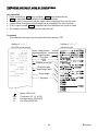
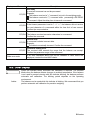
5.
Weighing Units
5.1. Units
The units and weighing modes can be selected and stored in the function table as described in
"5.2. Storing The Active Units".
The sequence of displaying them can be arranged to fit the frequency of use.
They are stored and are maintained in non-volatile memory, even if the AC adapter is removed.
If the law in your area permits, you may use all of the units. You can disable the units that you
don't regularly use. And you are able to turn them back on.
If a weighing mode (or unit of mass) has been turned off, that mode or unit will be missing in the
sequence. Tael has four varieties, one of which can be selected and installed at the factory.
Press the MODE key to select a unit or mode for weighing.
For details about the units and modes, see the table below:
Name (unit, mode)
Gram
Abbreviation
Display unit
g
Conversion factor
1g
Milligram
mg
Counting mode
PC
-
Percent mode
%
-
Ounce (Avoir)
oz
28.349523125 g
Troy Ounce
ozt
31.1034768 g
Metric Carat
ct
0.2 g
mom
3.75 g
Momme
0.001 g
Pennyweight
dwt
1.55517384 g
Grain (UK)
GN
0.06479891 g
Tael (HK general, Singapore)
Tael (HK jewelry)
Tael (Taiwan)
37.7994 g
37.429 g
tl
37.5 g
Tael (China)
31.25 g
Tola (India)
t
11.6638038 g
Messghal
m
Density mode
DS
4.6875 g
Refer to "14. Density Measurement"
Density mode
To use the density mode, it must be stored in the function table as described on page 17.
For details about this mode, refer to "14. Density Measurement".
To select this mode, press the MODE key until the processing indictor
"g" displayed.
14
blinks with the unit
BM series
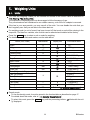
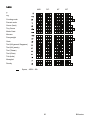
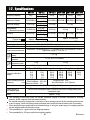
Capacity And Minimum Display For BM-252, BM-500, BM-300, BM-200
The tables below indicate the weighing capacity and the minimum display for each balance.
Unit
BM-500
BM-300
BM-200
Capacity
Minimum display
Gram
520
320
220
Milligram
520000
320000
220000
Ounce (Avoir)
18.34
11.29
7.76
0.00001
Troy Ounce
16.72
10.29
7.07
0.00001
Metric Carat
2600
1600
1100
0.001
Momme
138.7
85.3
58.7
0.0001
Pennyweight
334.4
205.8
141.5
0.0001
Grain (UK)
8024
4938
3395
0.002
Tael (HK general, Singapore)
13.76
8.47
5.82
0.00001
Tael (HK jewelry)
13.89
8.55
5.88
0.00001
Tael (Taiwan)
13.87
8.53
5.87
0.00001
Tael (China)
16.64
10.24
7.04
0.00001
Tola (India)
44.58
27.44
18.86
0.00001
Messghal
110.9
68.3
46.9
0.0001
Unit
BM-252
Capacity
Minimum display
Gram
250
Milligram
250000
Ounce (Avoir)
8.82
0.000001
Troy Ounce
8.03
0.000001
Metric Carat
1250
0.0001
Momme
66.67
0.00001
Pennyweight
160.7
0.00001
Grain (UK)
3858
0.0002
Tael (HK general, Singapore)
6.61
0.000001
Tael (HK jewelry)
6.68
0.000001
Tael (Taiwan)
6.67
0.000001
Tael (China)
8.00
0.000001
Tola (India)
21.43
0.000001
Messghal
53.3
0.00001
BM series
0.00001
0.01
15
0.0001
0.1
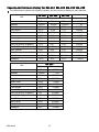
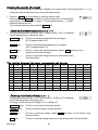
Capacity And Minimum Display For BM-22, BM-20
BM-22 is equipped the precision range and standard range of the smart range function.
BM-20
Unit
Precision range
Capacity
Minimum display
Gram
22
0.000001
Milligram
22000
0.001
Ounce (Avoir)
0.776
0.0000001
Troy Ounce
0.707
0.0000001
Metric Carat
110
0.00001
Momme
5.87
0.000001
Pennyweight
14.15
0.000001
Grain (UK)
339.5
0.00002
Tael (HK general, Singapore)
0.582
0.0000001
Tael (HK jewelry)
0.588
0.0000001
Tael (Taiwan)
0.587
0.0000001
Tael (China)
0.704
0.0000001
Tola (India)
1.886
0.0000001
Messghal
4.69
0.000001
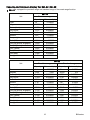
BM-22
Unit
Precision range
Capacity
Gram
5.1
Milligram
5100
Ounce (Avoir)
Minimum display
0.000001
Standard range
Capacity
22
Minimum display
0.00001
0.001
22000
0.01
0.180
0.0000001
0.776
0.000001
Troy Ounce
0.164
0.0000001
0.707
0.000001
Metric Carat
25.5
0.00001
110
0.0001
Momme
1.36
0.000001
5.87
0.00001
Pennyweight
3.28
0.000001
14.15
0.00001
Grain (UK)
78.71
0.00002
339.5
0.0002
Tael (HK general, Singapore)
0.135
0.0000001
0.582
0.000001
Tael (HK jewelry)
0.136
0.0000001
0.588
0.000001
Tael (Taiwan)
0.136
0.0000001
0.587
0.000001
Tael (China)
0.163
0.0000001
0.704
0.000001
Tola (India)
0.437
0.0000001
1.886
0.000001
Messghal
1.09
0.000001
4.69
0.00001
16
BM series
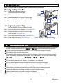
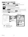
5.2. Storing Active Units
The units and modes can be selected and stored in the function table.
The sequence of displaying them can be arranged to fit the frequency of use.
The units stored are maintained in non-volatile memory, even if the AC adapter is removed.
1 Press and hold the RANGE key until ba5fnc of
the function table is displayed in the weighing mode,
then release the key.
2 Press the RANGE key several times to display Unit .
Press and hold
Press several times
3 Press the PRINT key to enter the unit selection mode.
4 Specify a unit or mode in the order to be displayed
using the following keys.
RANGE key .........To display the units sequentially.
RE-ZERO key ......To specify a unit or mode.
The indicator
appears when
the displayed unit or mode is specified.
Examples
Unit
Display
Gram
g
Milligram
mg
Counting mode
PC
Percent mode
%
Density mode
DS
5 Press the PRINT key to store the units or modes.
The balance displays end and then displays the next
menu item of the function table.
6 Press the CAL key to exit the function table.
Then the balance returns to the weighing mode with the
selected unit.
BM series
17
Selection key
Examples
Specify the unit
The indicator is
displayed at the
units specified.
Store them
5.3. Selecting Unit And Weighing Mode
Preset the sequence of displaying units and
weighing modes to fit the frequency of use.
Refer to "5.2 . Storing The Active Units".
The unit sequence of the factory settings.
Turning on the display.
Pressing the MODE key in the weighing mode,
the unit and weighing mode can be displayed in
order.
BM-20
BM-22
BM-252
BM-500
BM-300
BM-200
BM-22 and BM-20 are preset units in the
factory.
(Milligram),
(Gram) is displayed
in order.
For BM-252, BM-500, BM-300 and BM-200
are preset units in the factory.
(Gram),
(Milligram) is displayed in order.
Density mode
To use the density mode, it must be stored in
the function table as described on page 17.
Refer to "14. Density Measurement" for
details about the mode.
To select this mode, press the MODE key
until the processing indictor
blinks with
the unit "g" displayed.
Counting mode
Percent mode
Ounce (Avoir)
Troy Ounce
Metric Carat
Momme
Pennyweight
Grain (UK)
Tael
Tola (India)
Messghal
Density mode
18
BM series
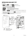
5.3.1.
Unit Setting Example
The example below sets the units in the order with g (gram) as the first unit followed by PC
(counting mode).
1 Press and hold the RANGE key until ba5fnc of the
function table is displayed in the weighing mode, then release
the key.
2 Press the RANGE key several times to display Unit .
Press and hold
Press several times
3 Press the PRINT key to enter the unit selection mode.
4 Press the RE-ZERO key to specify the unit of g.
The stabilization indicator
appears when the unit is
specified.
5 Press the RANGE key several times to display Unit
6 Press the RE-ZERO key to specify the unit of pcs.
The stabilization indicator
appears when the unit is
specified.
7 Press the PRINT key to store the units.
The balance displays end and then displays the next
menu item of the function table.
8 Press the CAL key to exit the function table. Then the
balance returns to the weighing mode with g, the unit
selected first.
9 Press the MODE key to switch between g and PC.
BM series
19
Specify gram
.
Press several times
Specify counting mode
Store them
6.
Weighing
Precautions for the weighing operation
Press the RE-ZERO key each time, before placing a sample on the weighing pan, to prevent
possible errors.
Place a sample in the center of the weighing pan gently.
Temperature changes during measurement may cause weighing error.
Shorten the operation time as much as possible. (Opening and closing door, putting and removing sample)
Use a pair of tweezers to avoid a temperature change due to having your hand in the weighing
chamber.
Material with an electrostatic charge or that is magnetic may cause a weighing error.
Do not press keys with a sharp instrument (such as a pencil or ball point pen).
Do not drop things on the pan, or place a weight on the pan that is beyond the weighing range.
Calibrate your balance periodically to maintain weighing accuracy. Refer to section "8. Calibration".
Keep the area clean and dry.
Consider section "3. Precautions" for the weighing operation.
For precision weighing, keep the AC adapter connected to the balance.
6.1. Basic Operation (Gram Mode)
Refer to section "4. Display symbols and Key operation" before operation.
Note
When turning on the balance with a tare weight placed on
the pan, the balance automatically displays the zero display.
1 Turn on the balance using the ON:OFF key.
Press the key
to select a unit,
if necessary.
2 Select a preset unit using the MODE key, if necessary.
Tare
(Container)
3 Place the tare (container) on the weighing pan, if necessary.
Press the RE-ZERO key to cancel the tare weight.
Then zero is displayed.
Tare : A vessel placed on the pan, but not
Stabilization
to be included in the weighing data.
indicator
Example: Container.
Zero display
Weighing pan
Sample
4 Place a sample on the pan or in the container.
Close the door.
5 Wait for the stabilization indicator
displayed, then read the value.
Glass door is
not closed
to be
6 Remove the sample and container from the pan.
Close door
Stabilization
indicator
Information
Remove them
20
BM series
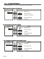
6.2. Smart Range For BM-22
The smart range for BM-22 consists of the standard range and precision range (high resolution).
Smart range function
These ranges can be switched by the weighing value automatically.
When placing the tare weight within the standard range, if pressing the RE-ZERO key, the
weighing sample can be weighed within the precision range.
When pressing RANGE key, the current range is fixed to the standard range.
Example
1 Press the RE-ZERO key to use the precision range.
The balance displays zero.
Precision range
Container (Tare)
2 Place the container (tare) on the weighing pan.
When mass of the container (tare) is within the
standard range, the current range is automatically
switched to the standard range.
Standard range
3 Press the RE-ZERO key to use the precision range.
The balance displays zero.
Precision range
Weighing matter
4 Place the weighing sample in the container (tare).
When the sample is within the precision range,
the weighing value can be read in high resolution.
Precision range
Precision Range And Standard Range For BM-22
Unit
Precision range
Standard range
Milligram
0.000
to 5100.009
5100.01
to 22000.84
Gram
0.000000
to 5.100009
5.10001
to 22.00084
Refer to page 14 for other units.
BM series
21
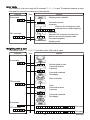
6.3. Counting Mode (PC)
This is the mode to determine the number of objects in a sample based on the standard sample
unit mass. The unit mass means an average mass of the samples. The smaller the variation in
the samples, the more accurate the count will be. The balance is equipped with the Automatic
Counting Accuracy Improvement (ACAI) function to improve the counting accuracy.
Notes
Use samples with a unit mass of 1 mg or more for counting.
If the sample unit mass variable is too large, it may cause a counting error.
To improve the counting performance, use the ACAI function frequently or divide the samples into
several groups and count each group.
Selecting the counting mode
1 Press the MODE key to select the unit
(counting mode).
Storing a sample unit mass (Weighing input mode)
2 Press the RANGE key to enter the sample unit mass storing mode.
3 Select the number of samples using the RANGE key.
It may be set to 10, 25, 50 or 100.
Advise A greater number of samples will yield more accurate
counting result.
4 Place a tare (container) on the weighing pan, if necessary.
Press the RE-ZERO key to cancel the weight (tare).
The number specified in step 3 appears.
Example: 25 0
is displayed if 25 is selected in step 3.
Weighing pan
Tare
(Container)
5 Place the number of samples specified on the pan.
In this example, 25 pieces.
6 Wait for the stabilization indicator to be displayed.
Press the PRINT key to calculate and store the unit mass.
Then the balance displays 25
and is set to count samples
with this unit mass. To improve the accuracy of the unit mass,
proceed to step 8.
Notes
If the balance judges that the mass of the samples is too light to
acquire accurate weighing, it displays an error requiring the
addition of more samples to the specified number.
Example: 50 appears, requiring 25 more samples. Add
25 samples and press the PRINT key. When the unit mass is
stored correctly, the balance proceeds to the counting mode.
25 samples
To Step 8 when using
the ACAI function.
If the balance judges that the mass of the samples is too light (under
0.0001g) and can not be stored as the unit mass, it displays lo .
The sample unit mass is stored in non-volatile memory, and is
maintained even if the AC adapter is removed.
Counting Operation
7 Place the samples to be counted on the pan.
Read the result and remove them from the pan.
22
Place samples
Counting result
BM series
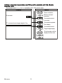
Counting mode using the ACAI function
The ACAI is a function that improves the accuracy of the unit mass automatically by increasing
the number of samples as the counting process.
ACAI: Automatic Counting Accuracy Improvement
Proceed to step 8 after storing a unit mass at last page.
8 If a few more samples are added, the processing
indicator turns on. To prevent an error, add three or
more. The processing indicator does not turn on if
overloaded. Try to add the same number of samples
as displayed.
9 The balance re-calculates the unit mass while the
processing indicator is blinking. Do not touch the
balance or samples on the pan until the processing
indicator turns off.
10 Counting accuracy is improved when the processing
indicator turns off.
Each time the above operation is performed, a more
accurate unit mass will be obtained. There is no
definite upper limit to the ACAI range for the number
of samples exceeding 100. Try to add the same
number of samples as displayed.
11 Remove all the samples used in ACAI and proceed
with the counting operation using the improved unit
mass.
BM series
23
From step 6
at last page
Add a few more
samples.
The mark turns on
at proper range.
The mark turns on
and off during
calculation.
The mark turns off
after the unit mass
is improved.
Repeat
6.4. Percent Mode (%)
The percent mode displays the weight value in percentage compared to a 100% reference mass
and is used for target weighing or checking the sample variance.
Selecting the percent mode
1 Press the MODE key to select the unit % (Percent mode).
If the percent mode can not be selected, refer to "5. Weighing Units".
Storing the 100% reference mass
2 Press the RANGE key to enter the 100% reference mass
storing mode.
3 Place a tare (container) on the weighing pan, if necessary.
Press the RE-ZERO key to cancel the weight (tare).
The balance displays 100 0 % .
4 Place the sample to be set as the 100% reference mass on
the pan or in the container.
5 Press the PRINT key to store the reference mass.
The balance displays 100.00 % .
Weighing pan
Tare
(Container)
100% mass
Note
The decimal point position can be changed by the 100% mass.
BM-252, BM-500
BM-20, BM-22
BM-300, BM-200
Minimum
Minimum
100% mass
100% mass
display
display
0.0100 g to 0.0999 g 1 %
0.00100 g to 0.0099 g 1 %
0.1000 g to 0.9999 g 0.1 %
0.01000 g to 0.0999 g 0.1 %
1.0000 g to
0.01 %
0.10000 g to
0.01 %
If the balance judges that the mass of the sample is too light
(under 0.01g) to be used as a reference, it displays lo .
A 100% reference mass can be stored in the non-volatile
memory and is maintained even if the AC adapter is removed.
6 Remove the sample.
Reading the percentage
7 Place a sample to be compared to the reference mass on
the pan. The displayed percentage is based on the 100%
reference mass.
24
Place sample
Percentage
BM series
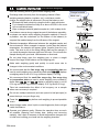
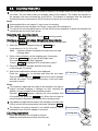
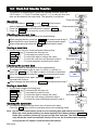
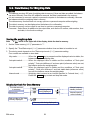
6.5. Built-in DC Static Eliminator (Neutralization Device)
The BM series is equipped with four DC static eliminator electrode units to neutralize static
electricity from a charged weighing sample.
When neutralizing static electricity before weighing, stability can be improved, reducing error.
Neutralizing ion : The discharge electrodes of the built-in DC static eliminator continuously
generate bipolar ions by corona discharge. Applying these ions to the weighing
sample neutralizes the static charge.
Static electricity : In general, when the ambient humidity is less than 45%RH, powders, paper,
plastic, nonconductors, etc., easily become charged with static electricity. The
influence of the static electricity may cause a weighing error of several
milligrams. The static eliminator effectively neutralizes the electrical charge.
Operation
1 Place the sample to be weighed on the center
(of the metallic circle) of the separation plate to
neutralize the static charge.
LED
Static eliminator
Sample
2 Press the ION key to start the neutralization.
The
mark and the LED flash.
The neutralization will stop after the preset time
of "Neutralizing time (ion)" in the function table
(the factory setting is 3 seconds).
Separation plate
The minimum display of BM-20, BM-22 and BM-252 is
switched to 0.1 mg while performing the neutralization.
When pressing the ION key during the neutralization,
the neutralization stops.
Key
In the neutralization
Weighing display
Note
Keep a space between electrodes and the weighing sample.
Example: Display of BM-20,
Placing the sample to close to an electrode may cause the
BM-22, BM-252
sample to become charged.
Remove any obstacle between electrodes and the weighing sample.
Maintenance Of The Electrode Unit
In general, when using the eliminator for a long time, dust and
stains may stick to the electrodes. Clean them periodically to
maintain performance.
When pins of the electrode are rubbed down and the
neutralization function does not recover after cleaning them,
replace the electrodes with four new units. The standard life
time is approximately 10000 hours.
Step 1
Step 2
Cleaning
Replacing Electrode Unit
Electrode
1 Turn the electrode unit 45 degrees counterclockwise. Remove it.
2 Replace all four units with new ones at the same time.
Electrode unit
Note
Do not remove and clean the electrodes while the
BM series
25
mark and the LED are flashing.
Remote Control Of The DC Static Eliminator
When specifying "on" to [AD8922 control] in the function
settings (8922 ionfnc on), the balance applies the function
of the ION key to the MODE key on the AD-8922.
When specifying "2" to [External control input ] in the function
settings (e-5 ionfnc 2) and assembling external key plug
(AX-T-314A-S) and foot switch (AX-SW128), the balance
applies the function of the ION key to the foot switch
Applies the ION key
to the MODE key on
the AD-8922A.
Example:
External key plug
(AX-T-314A-S)
Terminal 1
Line 1
GND
Applies the ION key to
terminal 1of the foot
switch (AX-SW-123).
Description Of The External Key Plug (AX-T-314A-S) (Option)
External key plug
AX-T-314A-S
Terminal 2
Terminal 1
Line 1
Line 2
GND
Terminal GND
When specifying [External control input (e-5)] in [Static eliminator (ionfnc)], the following
functions can be applied to the external key plug (AX-T-314A-S) terminals.
Static eliminator
External control input
ionfnc
e-5 0
ionfnc
e-5 1
ionfnc
e-5 2
Terminal 1
PRINT key
PRINT key
ION key
Terminal 2
RE-ZERO key
ION key
RE-ZERO key
factory settings
26
BM series
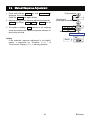
6.6. Monitoring Clock and Environmental Sensors
In the weighing mode, the built-in clock and environmental sensors (temperature, humidity, air
pressure) can be monitored and temperature data can be output with the function settings.
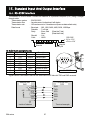
Specifications Of The Environmental Sensors
Sensor
Temperature
Humidity
Air pressure
Resolution Measurement range
±1.5 °C
5 °C to 40 °C
±10 %
0 % to 100 %
±10 hPa 300 hPa to 1100 hPa
Applicable range
5 °C to
40 °C
Caution
The environmental sensors are built into the case. Therefore, these values are not in accordance
with the environmental condition.
Refer to "17. Specifications" for operating condition of the product.
Operation
Press the SELECT key in the weighing
mode. The current time, date and sensor
values (temperature, humidity, air pressure)
are displayed for several seconds in order.
The balance returns to the weighing mode
automatically.
If pressing the SELECT key while
displaying current data, the display
proceeds to next data.
If pressing the CAL key while
displaying current data, the balance
returns to weighing mode.
Weighing mode
Time
5 seconds
Date
5 seconds
Environmental sensors
10 seconds
Humidity
Air pressure
Temperature
Weighing mode
Note
If adjusting the built-in clock, refer to "10.7.Clock And Calendar Function".
If appending time and date to data output, refer to the [Time/Date output (5-td)] of
"10.2.Details Of The Function Table".
If appending temperature data to the data output, refer to [Temperature output (5-tp)] of
"10.2.Details Of The Function Table".
BM series
27
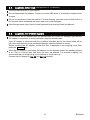
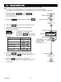
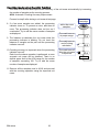
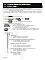
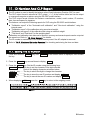
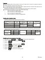
6.7. Repeatability Test
The repeatability means the weighing error when measuring the same mass repeatedly.
The standard deviation is generally used for the indicator of the repeatability.
The repeatability test measures the built -in mass 10 times and displays the standard deviation.
Use the repeatability test to inspect the performance of the balance when changing environment
or when moving the balance to a new location.
Example: "The standard deviation = 0.2 mg" means that the probability of weighing error within
±0.2 mg is approx. 68% when measuring the same mass repeatedly.
Note
The repeatability test uses the internal mass. Therefore, the standard deviation discords to item
repeatability of "17.Specifications". Regard the standard deviation as a reference.
Products
Internal mass
BM-20, BM-22
Approx.
BM-252, BM-500, BM-300, BM-200
Approx. 190 g
1 Press and hold the RANGE key,
Release the key when displaying rep te5t .
20 g
Example of BM-20
Weighing mode
Press and hold
2 When displaying rep te5t , the measurement
is automatically started, "r"e"p blinks and the
measurement count (0 to 10) is displayed.
When stopping the current measurement,
press the CAL key.
Note
Counter
In measurement
Avoid vibration and breezes for precise
measurement during this test.
3 At the end of the measurement,
the standard deviation of the
repeatability is displayed.
Release
Stop
Result
The standard deviation
or
4 Press the CAL key or PRINT key
to return to weighing mode.
Weighing mode
28
BM series
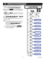
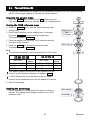
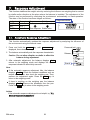
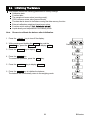
7.
Response Adjustment
This function stabilizes the weight value by reducing the influence on weighing that is caused
by drafts and/or vibration at the place where the balance is installed. The adjustment of the
function can be performed by analyzing the environment automatically or hand-operation.
The state of the function has three stages as follows :
Response indicator
Indicator Parameter Response
Stability
FAST
Cond 0
Fast response, Sensitive value
MID.
Cond 1
Slow response, Stable value
SLOW
Cond 2
7.1. Automatic Response Adjustment
This function automatically updates the response adjustment by analyzing the influence of
the environment using the internal mass.
1 Press and hold the MODE key until
displayed, then release the key.
RESPONSE
is
2 The balance automatically sets the response characteristic.
Caution Do not allow vibration or drafts to affect the
balance during adjustment.
3 After automatic adjustment, the balance displays end ,
returns to the weighing mode and displays the updated
response indicator for about thirty seconds.
Note
If the automatic response adjustment fails, the balance
displays CH ng . Check the ambient conditions such as
breeze and vibration, also check the weighing pan. Then,
perform the adjustment again. Press the CAL key to
return to the weighing mode.
If there is anything on the weighing pan, the balance
displays CH 0 . Remove the substance from the pan.
Press the CAL key to return to the weighing mode.
Advise
If the automatic response adjustment is not helpful, try "7.2.
Manual Response Adjustment".
BM series
29
Press and hold
Release
Result
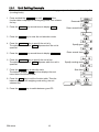
7.2. Manual Response Adjustment
1 Press and hold the MODE key until RESPONSE is
displayed, then release the key.
Press the MODE key again quickly.
2 Select a setting for the response adjustment using the
MODE key. Either FAST , MID. or SLOW can be
selected.
3 The balance displays 1end1, returns to the weighing
mode and displays the updated response indicator for
about thirty seconds.
Advise
If the automatic response adjustment is not helpful,
specify a parameter for "Condition (Cond) " of
"Environment, Display (ba5fnc)" with key operation.
30
Press and hold
Release and
press again immediately
Select a parameter
Release and wait
Result
BM series
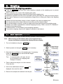
8.
Calibration (To Adjust The Weighing Value)
8.1. Calibration Group
Calibration
Automatic self calibration (Calibration due to changes in temperature)
Calibration using the internal mass (One-touch calibration)
Calibration using an external weight that you have
Calibration test
Calibration test using the internal mass
Calibration test using target mass that you have
Correction of the internal mass value
Correction of the internal mass value
Caution
Do not allow vibration or drafts to affect the balance during calibration.
Calibration test does not perform calibration.
When using the data output for GLP using the RS-232C interface, set "GLP output (info)" of the
function table. Refer to "10. Function Table". Time and date can be added to the GLP report. If it
is incorrect, refer to "10.7 Clock and Calendar Function" and adjust them.
Calibration test is available only when "GLP output (info)" is set .
The calibration and calibration test data can be stored in memory. When using memory, set "Data
memory (data)" of the function table. Refer to "12. Data Memory" for details.
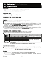
Caution on using an external weight
The accuracy of an external weight can influence the accuracy of weighing.
Select a mass for calibration and calibration test from the following table.
Model
BM-20
BM-22
BM-252
BM-200
BM-300
BM-500
1g
1g
10 g
50 g
50 g
50 g
Usable calibration mass
2g
5g
10 g
2g
5g
10 g
20 g
50 g
100 g
100 g
200 g*
100 g
200 g*
300 g
100 g
200 g*
300 g
Adjustable range
20 g*
20 g*
200 g*
-3.000 mg to +3.099 mg
-15.00 mg
to +15.99 mg
-30.0 mg
to +30.9 mg
500 g
Bold type*: Factory setting.
The calibration mass value can be adjusted within the range above.
About the internal mass
The internal mass may change due to corrosion or other damage caused by the operating
environment, or due to aging. Check the internal mass periodically and correct the internal mass
value if necessary. Refer to "8.7. Correcting the Internal Mass Value".
Display
BM series
This indicator means "In process of measuring calibration data".
Do not allow vibration or drafts to affect the balance while the indicator is
displayed.
31
8.2. Automatic Self Calibration (For variation of ambient temperature)
Automatic self calibration due to changes in temperature
This function automatically calibrates the balance when the balance detects an ambient
temperature change. If GLP output is selected in the function table, the balance outputs the
calibration report or stores the data in memory. Automatic self calibration functions even if the
display is turned off (standby state). Refer to "9.1. Permit Or Inhibit" for the operation.
Caution
Place nothing on the weighing pan during automatic self calibration.
If something is on the weighing pan, the balance decides that it is in use and does not
perform automatic self calibration.
When weighing a light sample, using a long term weighing or installing the balance in a
system, turn off automatic self calibration.
Note
When turning on the balance with nothing on the pan, if a sample heavier than 0.5 g is
placed on the pan, the balance detects the state that a sample is placed on the pan and
does not perform the automatic self calibration.
The mark
is " prior notice indicator of automatic self calibration".
When the balance detects a change in ambient temperature, this indicator blinks
and automatic self calibration is required. If the balance is not used for several
minutes with this indicator blinking, the balance performs automatic self calibration.
The environment will affect the time that the indicator blinks.
The balance is measuring calibration data. Do not allow vibration or drafts to affect
the balance while this indicator is displayed. After calibration, the balance returns
to indicate the previous display.
Advise
The balance can be used while the indicator blinks. But, it is recommended that to maintain the
accuracy, stop using the balance and confirm that there is nothing on the pan and allow the
balance to perform self calibration.
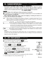
8.3. One-Touch Calibration (For Common Use)
This function calibrates the balance using the internal mass.
The only operation required is to press the CAL key.
1 Connect the AC adapter and warm up the balance for at
least one hour with nothing on the weighing pan.
2 Press the CAL key to display Cal in .
3 The balance performs calibration using the internal mass.
Do not allow vibration or drafts to affect the balance.
4 If GLP output is set, glp is displayed, the calibration test report
is output to the RS-232C interface and is stored in memory. Refer
to "GLP output (info)" and "Data memory (data)" of the function
table, "11.2. GLP Report" and "12. Data Memory".
end is displayed after the calibration.
GLP output
5 The balance will automatically return to the weighing mode after calibration.
6 Confirm weighing accuracy using calibration test (CC in).
32
BM series
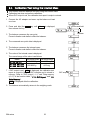
8.4. Calibration Test Using the Internal Mass
This function tests the balance accuracy using the internal mass.
Calibration test does not perform calibration.
When GLP output is set, the calibration test report is output or stored.
1 Connect the AC adapter and warm up the balance at least
one hour.
2 Press and hold the CAL key until CC in is displayed,
then release the key.
Press and hold
Release
3 The balance measures the zero point.
Prevent vibration and drafts to affect the balance.
4 The measured zero point data is displayed.
5 The balance measures the internal mass.
Prevent vibration and drafts to affect the balance.
6 The value of the internal mass is displayed.
The normal range of the value is as follows:
Model
BM-20, BM-22
BM-252, BM-200
BM-300, BM-500
The internal mass The normal range
20.00000 g
±0.02 mg
200.0000 g
±0.2 mg
7 If GLP output is set, glp is displayed, the calibration test
report is output to the RS-232C interface and is stored in
memory. Refer to "GLP output (info)" and "Data memory
(data)" of the function table, "11.2. GLP Report" and "12.
Data Memory".
end is displayed after the calibration.
9 The balance automatically returns to the weighing mode.
BM series
33
GLP output
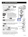
8.5. Calibration Using An External Weight
This function calibrates the balance using an external weight.
1 Connect the AC adapter and warm up the balance for at
least one hour with nothing on the weighing pan.
2 Press and hold the CAL key until
displayed, then release the key.
Calout
Press and hold
is
New mass
value
3 When displaying Cal 0 , proceed as follows:
If you want to change the calibration mass, press
the RANGE key and proceed to step 4.
If you use the calibration mass value stored in
the balance, proceed to step 5.
Select a type
4 Specify the calibration mass value as follows:
RANGE key .......... The key to switch blinking figures.
RE-ZERO (+)key..... The keys to select the calibration mass or
MODE (-)key
adjust the mass value. Refer to page 31.
PRINT key ............ The key to store the new mass value.
Even if the AC adapter is removed, the
data is maintained in non-volatile memory.
...............
CAL key
The key to cancel the operation and
return to Cal 0 .
5 Confirm that there is nothing on the pan and press the
PRINT key. The balance measures the zero point.
Do not allow vibration or drafts to affect the balance.
The balance displays the calibration mass value.
Specify detail of value
Example:
New value
100.0012 g
6 Place the displayed calibration weight on the pan and press
the PRINT key. The balance measures the calibration mass.
Do not allow vibration or drafts to affect the balance.
7
Release
is displayed.
Remove the weight from the pan.
Place the weight
end
Remove the weight
8 If GLP output is set, glp is displayed and the calibration
report is output and stored. Refer to "GLP output (info)" and
"Data memory (data)" of the function table, "11.2. GLP
Report" and "12. Data Memory".
GLP output
9 The balance will automatically return to the weighing mode.
10 Place the calibration weight on the pan and confirm that the
value displayed is correct. If it is not within the range, check
the ambient conditions such as breeze and vibration also
check the weighing pan. Then, repeat steps 1 to 10.
34
BM series
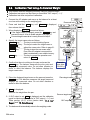
8.6. Calibration Test Using An External Weight
This function tests the weighing accuracy using an external weight.
Calibration test report can be output or stored with "GLP output (info)"
Calibration test does not perform calibration.
1 Connect the AC adapter and warm up the balance for at least
one hour with nothing on the weighing pan.
2 Press and hold the CAL key until CC out is displayed,
then release the key.
3 When displaying CC 0 , proceed as follows:
If the target mass is changed, press the RANGE key and
proceed to step 4. A list of usable weights is on page 31.
If current target mass value is used, proceed to step 5.
4 Specify the target mass value as follows:
RANGE key ........ The key to switch blinking figures.
RE-ZERO (+)key ... The keys to select the target mass or
MODE (-)key
adjust the mass value. Refer to page 31.
..........
PRINT key
The key to store the new mass value.
Even if the AC adapter is removed, the
data is maintained in non-volatile memory.
.............
CAL key
The key to cancel the operation and
return to CC 0 .
5 Confirm that there is nothing on the pan and press the
PRINT key. The balance measures the zero point and
displays the measured value. Do not allow vibration or
drafts to affect the balance. The balance displays the
target mass value.
6 Place the displayed target mass on the pan and press the
PRINT key. The balance measures the target mass and
displays the measured value. Do not allow vibration or
drafts to affect the balance.
7
Press and hold
New mass
value
Select a type
Specify detail of value
Example:
New value
100.0012 g
Place target mass
is displayed.
Remove the weight from the pan.
end
Remove target mass
8 If GLP output is set, glp is displayed and the calibration
report is output and stored. Refer to "GLP output (info)" and
"Data memory (data)" of the function table, "11.2. GLP
Report" and "12. Data Memory".
9 The balance will automatically return to the weighing mode.
BM series
35
GLP output
Release
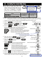
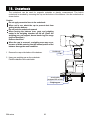
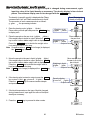
8.7. Correcting The Internal Mass Value
The balance can correct the internal mass
value within the range shown below. This
function corrects the internal mass value to
conform to an external weight. The corrected
mass value is maintained in non-volatile
memory even if the AC adapter is removed.
The internal mass value is corrected as follows:
Model
The same mass
200g
Correct the internal mass
by +0.6mg at 200g.
200.0000 g
200.0006 g
Calibrate with this
internal mass.
200g
Corrected external weight
The internal mass
BM-20, BM-22
The normal range
±0.15 mg
20.00000 g
BM-252, BM-200, BM-300, BM-500
±1.5 mg
200.0000 g
Example: 200.0000 g is corrected to +0.6 mg (200.0006 g). When using a 100 g external weight by
+0.6 mg for the correction, and the weight changed to 200 g, the correction value is +1.2 mg.
1 Perform one-touch calibration. Weigh an external weight and get the correction value.
2 Press the ON:OFF key to turn off the display.
Standby
3 While pressing and holding the PRINT key and the RANGE key,
press the ON:OFF key. p5 is displayed.
Press and hold Press
4 Press the PRINT key to display the function switches.
Set the function table switch and internal mass correction
switch to "1" as shown above using the following keys.
Function switch
RANGE key.......The key to select blinking figure.
RE-ZERO key....The key to change the value of the blinking figure.
PRINT key.........The key to store it and return to weighing mode.
CAL key ............The key to cancel current operation.
The internal mass correction switch
The function table switch
5 Press and hold the RANGE key to enter the function
table and release the key when ba5fnc is displayed.
Weighing mode
Press and hold
Function table
6 Press the RANGE key several times until C5 in is
displayed, then release the key.
7 Press the PRINT key.
Internal mass correction
Correct the internal mass value using the following keys.
RE-ZERO (+)key ....The key to increase the value.
MODE (-)key ........The key to decrease the value.
PRINT key...........The key to store the new value and display
the next menu item of the function table.
Corrected value
.............
CAL key
The key to cancel this correction and display
the next menu item of the function table.
8 Press the CAL key to return the weighing mode.
9 Press the CAL key to calibrate the balance using the internal mass.
10 Check that the correction has been performed properly with the
external weight. If the value is incorrect, repeat the correction.
36
Weighing mode
Perform one-touch calibration
BM series
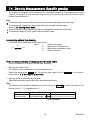
9.
Function Switch And Initialization
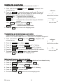
9.1. Permit Or Inhibit
The balance stores parameters that must not be changed unintentionally.
Example: Calibration data for accurate weighing, Data for adapting to the operating environment,
Control data for the RS-232C interface.
The balance is equipped with five switches for the purpose of protecting parameters. Each switch
can select either "permit" or "inhibit". "Inhibit" protects parameters against unintentional operations.
1 Press the ON:OFF key to turn off the display.
2 While pressing and holding the PRINT key and the RANGE key,
press the ON:OFF key to display p5 .
3 Press the PRINT key. Then the balance displays the function switches.
4 Specify the switches using the following keys.
RANGE key........... The key to select blinking digit.
RE-ZERO key........ The key to change the parameter for the selected switch.
0 To inhibit changes. (Can not be used.)
1 To permit changes. (Can be used.)
............
PRINT key
The key to store the new parameter and return to the weighing mode.
CAL key................ The key to cancel current operation and return to the weighing mode.
Function table
0 To inhibit changes to the function table.
1 To permit changes to the function table.
Calibration using the internal mass (One-touch calibration)
0 To inhibit calibration using the internal mass.
1 To permit calibration using the internal mass.
Calibration using the external weight
0 To inhibit calibration using the external weight.
1 To permit calibration using the external weight.
Automatic self calibration (for variation of ambient temperature)
0 To inhibit automatic self calibration.
1 To permit automatic self calibration.
Internal mass correction
0 To inhibit correction.
1 To permit correction.
BM series
37
9.2. Initializing The Balance
This function returns the following parameters to factory settings.
Calibration data
Function table
The sample unit mass value (counting mode),
100% reference mass value (percent mode)
The data that is stored in the balance using the data memory function
External calibration weight and target mass value
Function switch settings ("9.1. Permit Or Inhibit")
Liquid density and temperature in the density mode
Note
Be sure to calibrate the balance after initialization.
1 Press the ON:OFF key to turn off the display.
2 While pressing and holding the PRINT key and the
RANGE key, press the ON:OFF key to display
p5 .
Press and hold Press
3 Press the RANGE key to display Clr .
4 Press the PRINT key.
To cancel this operation, press the CAL key.
5 Press the RE-ZERO key to display Clr go .
6 Press the PRINT key to initialize the balance.
The balance will automatically return to the weighing mode.
38
BM series
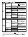
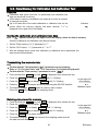
10. Function Table
The function table reads or rewrites the parameters that are stored in the balance.
These parameters are maintained in non-volatile memory, even if the AC adapter is removed.
The function table menu consists of two layers. The first layer is the "Class" and the second layer
is the "Item".
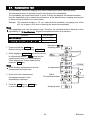
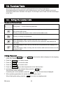
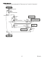
10.1. Setting The Function Table
Display symbol and keys
The symbol " " shows effective parameter.
When pressing and holding the key in the weighing mode, the balance enters
the function table mode.
The key to select the class or item in the function table mode.
The key to change the parameter.
When displaying a class, the key enters an item in the class.
When displaying an item, the key stores the new parameter and displays the
next class.
When displaying an item, the key cancels the new parameter and displays the
next class.
When displaying a class, the key exits the function table mode and returns to the
weighing mode.
Setting Procedure
1 Press and hold the RANGE key until ba5fnc of the function table is displayed in the weighing
mode, then release the key
2 Press the RANGE key to select a class.
3 Press the PRINT key to enter the class
4 Press the RANGE key to select a item.
5 Press the RE-ZERO key to select a parameter for the selected item.
6 If storing parameters of the selected class, press the PRINT key.
Then the next class is displayed.
If canceling the current operation, press the CAL key. Then the next class is displayed.
7 When specifying parameters for another class, proceed to step 2.
When finishing the setting, press the CAL key to return to weighing mode.
BM series
39
Setting Example
This example sets "Stores weighing data" for "Data memory" and "1 minute" for "Interval time".
Weighing mode
Start
Step 1
Press and hold
Step 2
Press several times
Class
Item
"Data memory"
Step 3
Step 4
Press several times
Step 5
Press 2 times
Parameter
"Stores weighing data"
Item
Step 5
Press 5 times
Step 4
Item
"Interval time"
Parameter
"1 minute"
Step 6
Step 7
Finish
Weighing mode
40
BM series
10.2. Details Of The Function Table
Class
Item and Parameter
Description
0 Fast response, sensitive value FAST
Cond
Can be changed by
1
MID.
response adjustment.
Condition
2 Slow response, stable value SLOW
0 Stable range is ±1 digit
The stabilization indicator
5t-b
1
±2 digit #1 illuminates when the display
Stability band width
fluctuation is within the range.
2 Stable range is ±3 digits
off OFF
ploc
Display hold function to measure the
volume dispensed from the pipette.
Display lock function
on ON
0 OFF
ba5fnc
1 Normal
trc
Keeps zero display by tracking
Environment
zero drift.
Zero tracking
2 Strong
Display
3 Very strong
0 5 times/second
5pd
Period to refresh the display
Display refresh rate
1 10 times/second
0 Point (.)
pnt
Decimal point format
Decimal point
1 Comma (,)
off OFF
p-on
Turns on the weighing mode display
when the AC adapter is connected.
Auto display-ON
on ON
off OFF
beep
Turns on the weighing mode display
when the AC adapter is connected.
Beep
on ON
Cl adj
The time and date are added to
Refer to "10.7. Clock and Calendar Function"
the output data.
Clock
Accepts the PRINT key only
0 Key mode
when the display is stable.
Auto print mode A
Outputs data when the display is
1
Reference
=
zero
stable and conditions of ap-p,
prt
ap-b and the reference value are
Auto print mode B
Data output mode
2
Reference = last stable value met.
With data 0, outputs data
Stream mode /
continuously; with data 2, uses
3
Interval mode
interval memory.
dout
0 Plus only
Displayed value > Reference
Data output ap-p
1 Minus only
Displayed value < Reference
Auto print polarity
2 Both
Regardless of displayed value
0 10 digits
ap-b
Difference between reference
value and displayed value
1 100 digits
Auto print
difference
#2
2 1000 digits
0 Not used
data
Related items:
1 Stores weighing data
prt, int, d-no, 5-td, info
Data memory
2 Stores calibration data
: Factory settings.
#1 The unit of minimum display is digit.
Example: If 1 mg display is selected using the RANGE key for the BM-300, 1 mg is one digit.
#2 Usable minimum display of the balance is one digit.
Example: In gram display, one digit is 0.01 mg for the BM-252 and 0.1 mg for the BM-300.
BM series
41
Class
Item and Parameter
0
1
2
3
int
4
Interval time
5
6
7
8
off
d-no
Data number output on
0
1
5-td
Time/Date
output
2
dout
Data output
3
off
5-id
ID number output
on
off
pU5e
Data output pause on
off
at-f
Auto feed
on
0
info
1
GLP output
2
off
ar-d
Zero after output
on
off
5-tp
Temperature output
on
0
1
2
bp5
Baud rate
3
4
5
0
btpr
1
5if
Data bit, parity bit
2
Serial
interface
0
Crlf
Terminator
1
0
1
2
type
Data format
3
4
5
Caution
Description
Every measurement
2 seconds
5 seconds
10 seconds
30 seconds
1 minutes
2 minutes
5 minutes
10 minutes
No output
Output
No output
Time only
Date only
Time and date
No output
Output
No pause
Pause (1.6 seconds)
Not used
Used
No output
AD-8121 format
General data format
Not used
Used
Not output
Output
600 bps
1200 bps
2400 bps
4800 bps
9600 bps
19200 bps
7 bits, even
7 bits, odd
8 bits, none
CR LF
CR
A&D standard format
DP format
KF format
MT format
NU format
CSV format
Interval time in the interval
memory mode when using prt
3,, data 1
Refer to "12. Data Memory"
Selects whether or not the time or
date is added to the weighting
data. Refer to "10.7. Clock and
Calendar Function" for details.
Selects whether or not the ID
number is output.
Selects the data output interval.
Selects whether or not automatic
feed is performed.
Selects GLP output method.
Refer to "11. ID Number And
GLP Report " for details.
Adjusts zero automatically after
data is output
Adds temperature to data output
CR: ASCII code 0Dh
LF: ASCII code 0Ah
Refer to "10.5. Description of
Item "Data Format" ".
: Factory settings.
The balance may not transmit the data completely at the specified refresh rate, depending
on the baud rate or data added to the weighing data such as time, date and ID number.
42
BM series
Class
5if
Serial
interface
d5 fnc
Density
function
Unit
Unit
Item and Parameter
off
t-Up
Timeout
on
off
erCd
AK, Error code
on
ldin
Liquid density input
Description
Selects the wait time to receive
a command.
No limit
1 second
No output
Output
AK: ASCII code 06h
0 Water temperature
1 Liquid density
Available only when density
mode is selected
Refer to "5. Weighing Units".
C5 in
Internal mass correction
Displayed only when the internal mass value correction
switch is set to 1. Refer to "8. Calibration (To Adjust The
Weighing Value)".
id
ID number setting
Refer to "11. ID Number And GLP Report".
ionfnc
Static
eliminator
0
1
2
off
8922
AD8922 control
on
0
e-5
1
External control input
2
door
Door state
function
d-dt
Door sensor
ion
Neutralization time
3 seconds
Refer to "6.5. Built-in DC
10 seconds
Static Eliminator" ".
Manual operation (max. 10 min.)
The ION key is not used.
Applies the ION key to the MODE key on AD-8922.
Applies the PRINT key and RE-ZERO key.
Applies the PRINT key and ION key.
Applies the ION key and RE-ZERO key.
off No used
on Used
: Factory settings.
10.3. Description Of The Class "Environment, Display"
Condition ( Cond )
Cond 0
This parameter is for sensitive response to the fluctuation of a mass value. Used for
powder target mass, weighing a very light sample or when quick response weighing is
required. After setting, the balance displays FAST .
Cond 2
This parameter is for stable weighing with slow response. Used to prevent a mass
value from drifting due to vibration or drafts. After setting, the balance displays SLOW .
In automatic response adjustment, this parameter is selected automatically.
Notes
Stability band width ( 5t-b )
This item controls the width to regard a mass value as a stable value. When the fluctuation per
second is less than the parameter, the balance displays the stabilization indicator and outputs or
stores the data. The parameter influences the "Auto print mode".
5t-b 0 This parameter is used for sensitive response of the stabilization indicator. Used for
exact weighing.
5t-b 2 This parameter ignores slight fluctuations of a mass value. Used to prevent a mass
value from drifting due to vibration or drafts.
BM series
43
Display Hold Function ( ploc )
This function is used to measure the volume dispensed from the pipette.
When specifying "Display lock function is used" (ploc on) in the function table, dispensing liquid
into the weighing bottle from the pipette and getting a stable weighing value, the balance
calculates an average value and displays the result (a fixed value).
When using this function for the measurement of a small volume, the influence of water
evaporation can be reduced.
Caution Even if using the weighing bottle (evaporator trap) to reduce the water
evaporation, at least 0.05 mg (0.05 ) evaporation will occur .
When canceling this function, press the CAL key.
In calculation. It blinks.
Processing indicator
Stable mark
Calculating
Fixed result
Zero tracking ( trc )
This function tracks zero point drift caused by changes in the environment and stabilizes the zero
point. When the weighing data is only a few digits, turn the function off for accurate weighing.
trc 0
The tracking function is not used. Used for weighing a very light sample.
trc 1
The normal tracking function is used.
trc 2
The strong tracking function is used.
trc 3
The very strong tracking function is used. Used for stable zero display.
Display refresh rate ( 5pd )
The periodic time to refresh the display. This parameter influences "Baud rate", "Data output
pause" and the data output rate of "Stream mode".
Decimal point ( pnt )
The decimal point format can be selected.
Auto display-ON ( p-on )
When the AC adapter is plugged in, the display is automatically turned on without the ON:OFF key
operation, to display the weighing mode. Used when the balance is built into an automated system.
One hour warm up is necessary for accurate weighing.
44
BM series
10.4. Description Of The Item "Data Output Mode"
The parameter setting of "Data output mode (prt)" applies to the performance when the "Data
memory (data)" parameter is set to "2" (to store the weighing data) and when the data is
transmitted using the RS-232C interface.
Key mode
When the PRINT key is pressed with the stabilization indictor turned on, the balance outputs or
stores the weighing data and the display blinks one time.
Required setting
dout
prt 0
Key mode
Auto print modes A and B
When the displayed value is stable and the conditions of "Auto print polarity", "Auto print
difference" and reference value are met, the balance outputs or stores the weighing data.
When the PRINT key is pressed with the stabilization indictor turned on, the balance outputs or
stores the data and the display blinks one time.
Auto print mode A
Example
Required setting
For weighing each time a sample is placed and removed, with "ar-d" set
to "1" (to adjust zero after the data is output).
dout
prt 1
Auto print mode A (reference = zero)
dout
ap-p
Auto print polarity
dout
ap-b
Auto print difference
dout
ar-d 1 Zero after output
Auto print mode B
Example
Required setting
For weighing while a sample is added.
dout
prt 2
Auto print mode B (reference = last stable value)
dout
ap-p
Auto print polarity
dout
ap-b
Auto print difference
Stream mode
The balance outputs the weighing data continuously regardless of the display condition. When the
display refresh rate is set to 5 times / second (5pd 0), the data output rate is also set to the same
5 times / second. The display does not blink in this mode. The interval memory mode is used
when the "Data memory (data)" parameter is set to "1" (to store the weighing data).
Example
For monitoring data on a computer.
Required setting
dout
prt 3
Stream mode
dout
data 0 Data memory function is not used
ba5fnc 5pd
Display refresh rate
5if
bp5
Baud rate
Caution The balance may not transmit the data completely at the specified refresh rate,
depending on the baud rate or time, date and ID number appended to the weighing data.
Interval mode
The weighing data is periodically stored in memory.
Example
For periodical weighing without a personal computer command and to
output all of the data, to a computer, at one time.
Required setting
dout
prt 3
Interval mode
dout
data 2
Data memory function is used
dout
int
Interval time
BM series
45
10.5. Description Of The Item "Data Format"
A&D standard format
5if type 0
This format is used when the peripheral equipment can receive the A&D format.
If an AD-8121B is used, set the printer to MODE 1 or 2.
This format consists of fifteen or sixteen characters excluding the terminator.
When numerical characters without a decimal point exceed eight characters for the BM-20, BM-22
and BM-252, the format becomes sixteen characters.
A header of two characters indicates the balance condition.
The polarity sign is placed before the data with the leading zeros. If the data is zero, the plus sign
is applied.
The unit, consisting of three characters, follows the data.
Header
Data
Stable header
Unstable header
Overload header
Header
Data
Unit
Terminator
Stable header of counting mode
Unit
Terminator
DP (Dump print) format
5if type 1
This format is used when the peripheral equipment can not receive the A&D format.
If an AD-8121B is used, set the printer to MODE 3.
This format consists of sixteen characters excluding the terminator.
A header of two characters indicates the balance condition. No overload header is used.
The polarity sign is placed before the data, with spaces in place of leading zeros, if the data
is not zero or overloaded.
The unit, consisting of three characters, follows the data.
Header
Data
Stable header
Unstable header
Unit
Terminator
Stable header of counting mode
KF format
5if type 2
This is the Karl-Fischer moisture meter format and is used when the peripheral equipment can
only communicate using this format.
This format consists of fourteen characters excluding the terminator.
This format has no header characters.
The polarity sign is placed before the data, with spaces in place of leading zeros, if the data is not
zero or overloaded.
This format outputs the unit only for a stable value.
Data
Unit Terminator
Stable value
Unstable value
46
BM series
MT format
5if type 3
A header of two characters indicates the balance condition.
The polarity sign is used only for negative data.
The weighing data uses spaces in place of the leading zeros.
The character length of this format changes dependent upon the unit
Header
Data
Unit Terminator
Stable header
Unstable header
Overload header
NU (numerical) format
5if type 4
This format outputs only numerical data.
This format consists of ten characters excluding the terminator.
The polarity sign is placed before the data with the leading zeros. If the data is zero, the plus sign
is used.
Data
Terminator
CSV format
5if type 5
This format separates the data of A&D standard format and the unit by a comma ( , ).
This format outputs the unit even when the data is overloaded.
When a comma ( , ) is selected for the decimal point, the separators are set to semicolon ( ; ).
When the ID number, data number, time and date are added at "Data output (dout)" of the
function table, outputs ID number, data number, date, time and weighing data in this order and
separates each item by a comma and treats all the items as one group of data.
ID number
Data number
Date
Time
Weighing data
ID number
dout 5-id 1
Data number
dout d-no 1
The number to identify a specific balance.
This format consists of eight characters excluding the terminator.
This format outputs the data number just before the data is transmitted using the RS-232C
interface.
This format consists of six characters excluding the terminator.
When CSV format (5if type 5) is selected, the period ( . ) is replaced with a comma ( , ).
Data number
BM series
Terminator
47
Date
dout 5-td 2 or 3
Time
dout 5-td 1 or 3
The date output order can be changed in " Time/Date output (5-td)" and "Clock (Cl adj)".
The year is output in a four-digit format.
This format outputs time in 24-hour format.
Temperature
dout 5-tp 1
This format outputs temperature. The unit is "C".
Caution Humidity and air pressure are not output.
48
BM series
10.6. Data Format Examples
Stable
Unstable
Overload
Positive error
Overload
Negative error
Space,
Carriage Return,
Line Feed,
BM series
ASCII 20h
ASCII 0Dh
ASCII 0Ah
49
Units
A&D
D.P.
KF
MT
g
mg
Counting mode
Percent mode
Ounce (Avoir)
Troy Ounce
Metric Carat
Momme
Pennyweight
Grain
Tael (HK general, Singapore)
Tael (HK, jewelry)
Tael (Taiwan)
Tael (China)
Tola (India)
Messghal
Density
Space, ASCII 20h
50
BM series
10.7. Clock And Calendar Function
The balance is equipped with a clock and calendar function. When the
"GLP output (info)" and "Time/Date output (5-td)" is used, the time and
date can be added to the output data. The operation is as follows:
Press and hold
Operation
1 Press and hold the RANGE key until ba5fnc of the function
table is displayed in the weighing mode, then release the key.
Press several times
2 Press the RANGE key several times to display Cl adj .
3 Press the PRINT key to enter the mode for the time and date.
Checking the current time
4 The current time is displayed with all the digits blinking.
When changing the time, press the RE-ZERO key and proceed to step 5.
When the time is correct, press the RANGE key and proceed to step 6.
When exiting the mode, press the CAL key and proceed to step 8.
The current
time
Storing a new time
5 Set the time in 24-hour format using the following keys.
RE-ZERO (+)key .To increase the value by one.
MODE (-)key .....To decrease the value by one.
RANGE key ......To select the digits to change the value.
PRINT key........To store the new time, and proceed to step 6.
CAL key ...........To cancel operation and proceed to step 6.
New time
Store new time
Checking the current date
6 The current date is displayed with all the digits blinking.
To change the display order of year (y), month (m) and day (d),
press the MODE key. The date is output in the order as specified.
When the date is correct, press the CAL key and proceed to step 8.
When changing the time again, press the RANGE key and
proceed back to step 4.
When changing the date, press the RE-ZERO key and proceed to step 7.
The current
date
Storing a new date
7 Set the date using the following keys.
RE-ZERO (+)key To increase the value by one.
New date
MODE (-)key .....To decrease the value by one.
RANGE key .....To select the digits to change the value.
Store new date
PRINT key .......To store the new setting, proceed to step 8.
CAL key ..........To cancel the new setting and proceed to step 8.
Quitting the operation
8 The balance displays the next menu item of the function table.
Press the CAL key to exit the mode and return to the weighing mode.
Note Do not enter invalid values such as a non-existing time and date in this function.
When the clock backup battery has been depleted, the balance displays rtc pf .
Under this condition, press any key and set the time and date. The dead battery
only affects the clock and calendar function. Even so, the function works normally
as long as the AC adapter is connected to the balance.
BM series
51
11. ID Number And GLP Report
The ID number is used to identify the balance when Good Laboratory Practice (GLP) is used.
The GLP output format is selected at "GLP output (info)" of the function table and can be output
to a personal computer or printer using the RS-232C serial interface.
The GLP output format includes the balance manufacturer, model, serial number, ID number,
date, time and space for signature.
The balance can output the following reports for GLP using the RS-232C serial interface.
"Calibration report" of the "Automatic self calibration" and "One-touch calibration" using the
internal mass.
"Calibration report" of the calibration using an external weight.
"Calibration test report" of the calibration test using an external weight.
"Title block" and "End block" for the weighing data.
Calibration and calibration test data can be stored in memory and several reports can be output at
the same time. Refer to "12. Data Memory" for details.
The ID number is maintained in non-volatile memory even if the AC adapter is removed.
Refer to "10.7. Clock and Calendar Function" for checking and storing the time and date.
11.1. Setting The ID Number
1 Press and hold the RANGE key until ba5fnc of the function table is displayed, then release
the key.
2 Press the RANGE key several times to display
id .
3 Press the PRINT key. Set the ID number using the following keys.
RE-ZERO key .....The key to set the character of the digit selected.
Refer to the display character set shown below.
RANGE key ........The key to select the digit to change the character.
PRINT key..........The key to store the new ID number and display ba5fnc .
CAL key .............The key to cancel the new ID number and display ba5fnc .
4 When displaying ba5fnc , press the CAL key to return to the weighing mode.
52
BM series
11.2. GLP Report
Set the following parameters to output the report.
Refer to "15.2. Connection to peripheral equipment" for connection to an AD-8121B.
To print the report, set the "GLP output (info)" parameter to "1" and use MODE 3 of the AD-8121B. If
MODE1 is used, select temporary dump print mode by pressing the STAT. key of the AD-8121B.
To output the report to a personal computer using the RS-232C interface, set the "GLP output (info)"
parameter to "2".
If the time and date are not correct set the correct time and date in "Clock (Cl adj)" of the function table.
Calibration report using the internal mass
Key operation
1 Press the CAL key to display Cal in and calibrate the balance automatically.
2 If GLP output is used, glp is displayed and the calibration report is output.
3 The balance returns to weighing mode after this calibration.
Setting of "info 1"
AD-8121 printer format
===========A=&=D
MODEL=====BM-300
S/N=====01234567
ID======LAB-0123
DATE==2011/02/20
TIME====12:34:56
CALIBRATED(INT.)
SIGNATURE
Setting of "info 2"
General format
Manufacturer
Model
Serial number
ID number
Date
Time
Calibration type
Signature
---------------
<TERM>
CR
LF
BM series
Space, ASCII 20h
Terminator, CR , LF or CR
Carriage return, ASCII 0Dh
Line feed, ASCII 0Ah
53
Calibration test report using an internal mass
Note Calibration test does not perform calibration.
Key operation
1 Press and hold the CAL key to display CC in and release the key.
2 CC is displayed and the balance is tested automatically.
3 The zero point is measured and the weight value is displayed for a few seconds.
4 Internal mass is weighed and the weight value is displayed for a few seconds.
5 If GLP output is used, glp is displayed and the calibration test report is output.
6 The balance returns to weighing mode after this test.
Command
This calibration test report can be performed with command TST.
Setting of "info 1"
AD-8121 printer format
-----------A-&-D
MODEL-----BM-300
S/N-----01234567
ID------LAB-0123
DATE--2011/02/20
TIME----12:34:56
CAL.TEST(INT.)
ACTUAL
-------0.0000--g
----+200.0002--g
TARGET
----+200.0000--g
SIGNATURE
Setting of "info 2"
General format
Manufacturer
Model
Serial number
ID number
Date
Time
Calibration test type
Zero point value
Target weight value
Target weight
Signature
---------------
<TERM>
CR
LF
Space, ASCII 20h
Terminator, CR , LF or CR
Carriage return, ASCII 0Dh
Line feed, ASCII 0Ah
54
BM series
Calibration report using an external weight
Key operation
1 Press and hold the CAL key to display Cal out and release the key.
2 Cal 0 is displayed.
3 When updating the calibration mass value, press the RANGE key and proceed to step 4.
When using the preset calibration mass value, proceed to step 5.
4 Specify calibration mass value using the following keys.
RANGE key ........The key to select the blinking figure
RE-ZERO (+)key...The key to increase the value of the blinking figure.
MODE (-)key .......The key to decrease the value of the blinking figure.
PRINT key .........The key to store the new value.
5 When pressing the RE-ZERO key, the zero point is measured and the weight value is displayed
for a few seconds.
6 Place the displayed mass on the pan. Press the PRINT key to measure the mass and the
weight value is displayed for a few seconds.
7 If GLP output is used, glp is displayed and the calibration report is output.
8 The balance returns to weighing mode after this calibration.
Setting of "info 1"
AD-8121 printer format
-----------A-&-D
MODEL-----BM-300
S/N-----01234567
ID------LAB-0123
DATE--2011/02/20
TIME----12:34:56
CALIBRATED(EXT.)
CAL.WEIGHT
----+200.0000--g
SIGNATURE
Setting of "info 2"
General format
Manufacturer
Model
Serial number
ID number
Date
Time
Calibration type
Calibration weight
Signature
---------------
<TERM>
CR
LF
BM series
Space, ASCII 20h
Terminator, CR , LF or CR
Carriage return, ASCII 0Dh
Line feed, ASCII 0Ah
55
Calibration test report using an external weight
Note Calibration test does not perform calibration.
Key operation
1 Press and hold the CAL key to display CC out and release the key.
2 Cal 0 is displayed.
3 When updating the target value, press the RANGE key and proceed to step 4.
When using preset target value, proceed to step 5.
4 Specify calibration mass value using the following keys.
RANGE key .......... The key to select the blinking figure
RE-ZERO (+)key .... The key to increase the value of the blinking figure.
MODE (-)key ......... The key to decrease the value of the blinking figure.
PRINT key............ The key to store the new value.
5 When pressing the RE-ZERO key, the zero point is measured and the weight value is displayed for a few
seconds.
6 Place the displayed mass on the pan. Press the PRINT key to measure the mass and the weight value
is displayed for a few seconds.
7 If GLP output is used, glp is displayed and the calibration test report is output.
8 The balance returns to weighing mode after this test.
Setting of "info 1"
AD-8121 printer format
-----------A-&-D
MODEL-----BM-300
S/N-----01234567
ID------LAB-0123
DATE--2011/02/20
TIME----12:34:56
CAL.TEST(EXT.)
ACTUAL
-------0.0000--g
----+200.0002--g
TARGET
----+200.0000--g
SIGNATURE
Setting of "info 2"
General format
Manufacturer
Model
Serial number
ID number
Date
Time
Calibration test type
Zero point value
Target weight value
Target weight
Signature
---------------
<TERM>
CR
LF
Space, ASCII 20h
Terminator, CR , LF or CR
Carriage return, ASCII 0Dh
Line feed, ASCII 0Ah
56
BM series
Title block and end block
When mass values are recorded as GLP data, a "Title block" is inserted at the beginning and an
"End block" is inserted at the end of a group of mass values in the GLP report.
Notes
To output the report to an AD-8121B , use MODE 3 of the AD-8121B. If MODE1 is used, select
temporary dump print mode by pressing the STAT. key of the AD-8121B.
If the data memory function is used (except data 0), the "Title block" and "End block" can not be
output.
Key operation
1 With the weighing data displayed, press and hold the PRINT key, then release the key.
5tart is displayed. The "Title block" is output.
2 The weighing data is output according to the parameter setting of the data output mode (prt) of
the function table.
3 Press and hold the PRINT key until recend is displayed, then release the key.
The "End block" is output.
Setting of "info 1"
AD-8121 printer format
-----------A-&-D
MODEL-----BM-300
S/N-----01234567
ID------LAB-0123
DATE--2011/02/20
START
TIME----12:34:56
WT--+123.4567--g
WT--+123.4612--g
WT--+123.4623--g
WT--+123.4634--g
WT--+123.4511--g
WT--+123.4534--g
WT--+123.4712--g
WT--+123.4645--g
Title block
Manufacturer
Model
Serial number
ID number
Date
Time
Weighing data
END
TIME----12:40
15
SIGNATURE
Time
Signature
---------------
End block
<TERM>
CR
LF
BM series
Space, ASCII 20h
Terminator, CR , LF or CR
Carriage return, ASCII 0Dh
Line feed, ASCII 0Ah
57
Setting of "info 2"
General format
12. Data Memory
Data memory is a function to store weighing data and calibration data in memory. The data stored in
memory are available for outputting at one time to a printer or personal computer.
Weighing data
Excluding date and time
Up to 200 sets
Including date and time
Up to 100 sets
Calibration report
Internal calibration
External calibration
Calibration test report
Internal test calibration
External test calibration
Last 50 sets
12.1. Notes On Using Data Memory
To use the memory function, set the "Data memory (data)" parameter
and "Time/Date output (5-td)" parameter of the function table. Refer to
"10. The Function Table" for details on setting the data memory.
For weighing data, the data contents to be stored and the storage
capacity depend on the "Time/Date output (5-td)" parameter setting.
If a different type of data exists in memory, "Clr" blinks in the upper left
of the display.
For example: You want to store weighing data but calibration data or
unit mass data remains in memory. "Clr" blinks.
Upper left of
the display
If the stored data is incomplete or deleted, "err" blinks in the upper left
of the display.
Under such a condition, before storing data, delete the data in memory
as follows:
Releasing "Clr" or "err"
1 Press and hold the PRINT key until SClr "n"o with "no" blinking is displayed, then release the key.
2 Press the RE-ZERO key to display Clr "g"o with "go" blinking.
The type of data stored in memory appears in the upper left of the display as shown below:
Weighing data without time and date
Weighing data with time and date
Calibration report
-dd-t
Hi5
3 Press the PRINT key to delete all the data in memory.
4 The balance displays end and returns to the weighing mode.
58
BM series
12.2. Data Memory For Weighing Data
Features
The balance can store 200 sets of weighing data in memory (if time and date are added, the balance
can store 100 sets). Even if the AC adapter is removed, the data is maintained in the memory.
It is not necessary to connect a printer or personal computer to the balance continually, because
the balance stores the weighing data in memory.
The data memory function does not occupy a printer or personal computer while weighing.
The data in memory can be displayed on the balance for confirmation.
The data in memory can be output at one time to a printer or personal computer.
Comment: Select items for addition to the output data, such as the ID number, data number, time
and date, in the function settings.
Storing the weighing data
Note
If "Clr" blinks in the upper left of the display, delete the data in memory.
1 Set the "Data memory (data)" parameter to "1".
2 Specify the "Time/Date output (5-td)" parameter whether time and date is to added or not.
3 The storing mode depends on the "Data output mode (prt)" parameter setting.
Four modes are available to store data.
Key mode ........................... When the PRINT key is pressed and the displayed value is stable, the
balance stores the weighing data.
..............
Auto print mode A
When the displayed value is stable and the conditions of "Auto print
polarity", "Auto print difference" and zero point (reference value) are met,
the balance stores the weighing data.
Auto print mode B .............. When the displayed value is stable and the conditions of "Auto print
polarity", "Auto print difference" and last stable data (reference value)
are met, the balance stores the weighing data.
......................
Interval mode
Weighing data is stored at an interval specified in "Interval time (int)".
Press the PRINT key to start and stop this mode.
Display Symbols For Data Memory
The data amount
in memory
Memory full
Weighing data
being displayed
Data number of the data
currently displayed
Memory data being displayed
BM series
59
Interval memory
standby indicator
Interval memory
active indicator
Caution
When weighing data is being stored in memory, the data can be output to a personal computer
using the RS-232C interface at the same time.
"fUl" indicates that memory is full or the memory capacity has been reached. More data can not
be stored unless the memory data is deleted.
Automatic self calibration can not be used while the interval memory mode is active.
The following commands can not be used during data storage.
Q
Query command for weighing data.
S
Query command for stable weighing data.
SI
Query command for weighing data.
SIR Query command for continuous weighing data.
Setting the function table
Parameter settings for each output mode are as follows:
Item
Mode
Key mode
Auto print mode A
Auto print mode B
Interval mode
Data output
mode
prt 0
prt 1
prt 2
prt 3
Auto print polarity,
difference
Not used
ap-a 0 to 2
ap-b 0 to 2
Not used
Data memory
Interval time
function
data 1
Not used
data 1
data 1
data 1
int 0 to 8
Additional parameter settings, as follows:
Data number
ID number
No
Yes
No
Yes
d-no
d-no
5-id
5-id
off
on
off
on
Time and date
No
Time only
Date only
Both
5-td
5-td
5-td
5-td
0 200 sets
1
2 100 sets
3
Enabling the data memory function
1 Press and hold the RANGE key until ba5fnc is displayed, then release the key.
2 Press the RANGE key several times to display dout .
3 Press the PRINT key.
4 Press the RANGE key three times to display data .
5 Press the RE-ZERO key to display data 1 .
6 Press the PRINT key to store the setting.
7 Press the CAL key to return to the weighing mode.
60
BM series
Recalling the memory data
Confirm that the "Data memory (data)" parameter is set to "1".
1 Press and hold the PRINT key until reCall is displayed, then
release the key.
2 Press the PRINT key to enter the memory recall mode. The type of
data appears in the upper left of the display as shown to the right.
Recall the data in memory using the following keys.
RE-ZERO key .....To proceed to the next data set.
MODE key .........To go back to the previous data set.
PRINT key..........To transmit the current data using the RS-232C
interface.
With RANGE held down, press the CAL key
To delete the current data.
CAL key .............To exit the memory recall mode.
Indicators
Weighing data
without time and date
Weighing data with
time and date
3 Press the CAL key to return to the weighing mode.
Transmitting all memory data at one time
Confirm that the "Serial interface (5if)" parameters are set properly.
Refer to "10. Function Table" and "15.2. Connection To Peripheral Equipment".
1 Press and hold the
release the key.
PRINT
key until
reCall
is displayed, then
2 Press the RANGE key to display out .
3 Press the PRINT key to display out "n"o with "no" blinking.
Indicators
Weighing data
without time and date
5 Press the RE-ZERO key to display out "g"o with "go" blinking.
6 Press the PRINT key to transmit all data using the RS-232C interface.
7 The balance displays Clear when all data is transmitted.
Press the CAL key to return to the weighing mode.
Deleting all memory data at one time
Weighing data with
time and date
1 Press and hold the PRINT key until reCall is displayed, then release the key.
2 Press the RANGE key several times to display Clear .
3 Press the PRINT key to display Clr "n"o with "no" blinking.
4 Press the RE-ZERO key to display Clr "g"o with "go" blinking.
5 Press the PRINT key to delete all data
6 The balance displays end and returns to the weighing mode.
BM series
61
12.3. Data Memory For Calibration And Calibration Test
Features
Calibration data (when and how it is performed) and calibration test
data can be stored in memory.
All the data in memory is available to be output at one time to a printer
or personal computer.
Up to 50 data sets of the latest calibration or calibration test can be
stored. When the memory capacity has been reached, "fUl" is
displayed in the upper left of the display.
Indicator
Storing the calibration and calibration test data
Note If "Clr" appears blinking in the upper left of the display, delete the data in memory.
Store the calibration and calibration test data as follows:
1 Set the "Data memory (data)" parameter to "2".
2 Set the "GLP output (info)" parameter to "1" or "2".
3 With the settings above, each time calibration or calibration test is performed, the
data is stored automatically.
Transmitting the memory data
Note
Confirm that the "Serial interface (5if)" parameters are set properly.
Refer to "10. Function Table" and "15.2. Connection To Peripheral Equipment".
Confirm that the "Data memory" parameter is set to "data 2".
1 Press and hold the PRINT key until out is displayed, then release the key.
2 Press the PRINT key to display out "n"o with "no" blinking.
3 Press the RE-ZERO key to display out "g"o with "go" blinking.
In the upper left
of the display
4 Press the PRINT key to transmit all memory data using the RS-232C interface.
5 The balance displays Clear when all memory data is output.
Press the CAL key to return to the weighing mode.
Calibration report
Deleting data stored in memory
1 Press and hold the PRINT key until out is displayed, then release the key.
2 Press the SAMPLE key to display Clear .
3 Press the PRINT key to display Clr "n"o with "no" blinking.
In the upper left
of the display
4 Press the RE-ZERO key to display Clr "g"o with "go" blinking.
Calibration report
5 Press the PRINT key to delete all data.
6 The balance displays out and returns to the weighing mode when all
the data has been deleted.
62
BM series
13. Underhook
The underhook can be used for magnetic materials or density measurement. The built-in
underhook is revealed by removing the cap on the bottom of the balance. Use the underhook as
shown below.
Caution
Do not apply excessive force to the underhook.
When not in use, attach the cap to prevent dust from
getting into the balance.
Do not push the underhook upward
When turning the balance over, parts and weighing
matter in the weighing chamber will fall off. (Parts: the
weighing pan, pan support, breeze break ring, fine range
ring and dust plate )
Remove them first.
When the cap is removed, a weighing error may occur,
because of drafts entering into the internal portion of the
balance. Arrange the room condition.
Underhook
Cap
1 Remove the cap on the bottom of the balance.
2 Hang your weighing pan on the underhook.
Place the balance on the solid table.
Sturdy table
equipped with a hole.
Weighing pan
BM series
63
Bottom
14. Density Measurement (Specific gravity)
The balance is equipped with a density mode. It calculates the density of a solid using the mass
value of a sample in air and the mass value in liquid. We recommend the use of the AD-1653
Density Determination Kit.
Note
The density mode was not selected for use when the balance was shipped from the factory.
To use this mode, change the function table settings to activate the density mode.
Refer to "5.2. Storing Active Units".
When the density mode is selected, the response adjustment function can not be used.
The minimum display is 0.0001 g while using the density mode.
Formula to obtain the density
The density can be obtained by the following formula.
Where
ρ : Density of a sample
A
A : Mass value of a sample in air
ρ=
x ρ0
B : Mass value of a sample in liquid
A- B
ρ0 : Density of a liquid
Prior to measurement: Changing the function table
Prior to measurement, change the function table as follows:
1 Selecting the density mode.
The density mode is available as one of the weighing units.
Select it by pressing the MODE key. To use the mode, select it (unit of Unit
table. Refer to "5.2. Storing The Active Units".
.) in the function
2 Selecting a way to set the density of a liquid.
Select the liquid density input method from the function table below.
Note
The following function table is displayed only when the unit of Unit
density mode (d5 fnc) is displayed next 5if.
Class
d5 fnc
Density function
is active. The table of the
Item and Parameter
Description
ldin
0 Water temperature
Liquid density input
1 Liquid density
is factory setting.
64
BM series
Entering the density of a liquid
Two ways to set the density of a liquid are available in the function table, "Liquid density input (ldin): by
entering the water temperature or by entering the density directly.
1 Press the MODE key as necessary to select the density mode.
Press and hold the MODE key to select to "water temperature" or "liquid density".
In the density mode : The unit is "g (gram)". The processing indicator ( ) blinks.
Response adjustment is off.
If you cancel the density mode, press the MODE key.
Entering the water temperature ( ldin
0)
2 The water temperature currently set (unit:°C, factory setting : 25°C) is displayed.
Use the following keys to change the value.
RE-ZERO (+)key .... The key to increase the temperature by one degree.
(0°C is displayed after 99°C)
MODE (-)key ..........The key to decrease the temperature by one degree.
(99°C is displayed after 0°C)
PRINT key............The key to store new water temperature, display end and return to the
density mode. Proceed to Step 1.
CAL key...............The key to cancel the change and return to the density mode.
Proceed to Step 1.
The relation between the water temperature and density
°C
0
10
20
30
40
50
60
70
80
90
+0
+1
+2
+3
+4
+5
+6
+7
+8
+9
0.99984
0.99970
0.99820
0.99565
0.99222
0.98804
0.98320
0.97777
0.97180
0.96532
0.99990
0.99961
0.99799
0.99534
0.99183
0.98758
0.98268
0.97720
0.97117
0.96465
0.99994
0.99949
0.99777
0.99503
0.99144
0.98712
0.98216
0.97662
0.97054
0.96397
0.99996
0.99938
0.99754
0.99470
0.99104
0.98665
0.98163
0.97603
0.96991
0.96328
0.99997
0.99924
0.99730
0.99437
0.99063
0.98618
0.98110
0.97544
0.96927
0.96259
0.99996
0.99910
0.99704
0.99403
0.99021
0.98570
0.98055
0.97485
0.96862
0.96190
0.99994
0.99894
0.99678
0.99368
0.98979
0.98521
0.98001
0.97425
0.96797
0.96120
0.99990
0.99877
0.99651
0.99333
0.98936
0.98471
0.97946
0.97364
0.96731
0.96050
0.99985
0.99860
0.99623
0.99297
0.98893
0.98422
0.97890
0.97303
0.96665
0.95979
0.99978
0.99841
0.99594
0.99259
0.98849
0.98371
0.97834
0.97242
0.96600
0.95906
g/cm3
Entering the density directly ( ldin
1)
3
The density currently set (unit : g / cm , factory setting : 1.0000g / cm3) is displayed.
Use the following keys to change the value.
The range to set the density is 0.0000g / cm3 to 1.9999g / cm3.
RE-ZERO1(+)key.... The key to set the value of the digit selected.
RANGE1(-)key........ The key to select the digit to change the value.
PRINT key............ The key to store the change, display
end
and return to the density mode.
Proceed to Step 1.
CAL key ............... The key to cancel the change and return to the density mode. Proceed to Step 1.
BM series
65
Measuring the density ( specific gravity )
Note If the liquid temperature or the type of liquid is changed during measurement, again
input the value of the liquid density as necessary. The density display is four decimal
places. The minimum display can not be changed with the RANGE key.
The density (or specific gravity) is displayed after "Mass
measurement in air" and "Mass measurement in liquid".
The procedure of each measurements is as follows:
g : gram.
: the processing indicator.
1 Enter the density mode. (g lights.
blinks.)
Place nothing on both pan and press the RE-ZERO key
to display zero.
2 Place the sample on the pan in air. (g lights.
blinks.)
If the weight value is stored or output, press the PRINT
key to store it after a stable weight value is displayed.
Press the RANGE key to decide the weight value
in air and proceed to next step.
Note If negative value or e (out of range) is displayed,
the RANGE key is inactive.
3 Move the sample to the pan in liquid. (g lights. lights.)
If the weight value is stored or output, press the PRINT
key to store it after a stable weight value is displayed.
Press the RANGE key to decide the weight value in
liquid and proceed to next step.
Note If e (out of range) is displayed, the RANGE key
is inactive.
4 If the density value is stored or output, press the PRINT
key to store it. (Unit : . g turns off.
lights.)
Press the RANGE key to measure another sample
and proceed to step 2.
From "Entering the
density of a liquid"
Weighing in air.
g lights.
blinks.
Place sample on
the pan in air
Weighing in air.
g lights.
blinks.
Output or store
Move sample from
the pan in air to the
pan in liquid
Weighing in liquid.
lights.
g lights.
Output or store
Density display.
g turns off.
lights.
Output or store
Remove sample
5 If the liquid temperature or the type of liquid is changed
during measurement, input again the value of the liquid
density as necessary.
6 Press the MODE key to proceed to other modes.
66
BM series
15. Standard Input And Output Interface
15.1. RS-232C Interface
The balance is a DCE device. Connect the balance to a personal computer (DTE) using a straight
through cable.
Transmission system
: EIA RS-232C
Transmission form
: Asynchronous, bi-directional, half duplex
Transmission rate
: 10 times/second or 5 times/second (same as data refresh rate)
Data format
: Baud rate : 600, 1200, 2400, 4800, 9600, 19200bps
Data bits : 7 or 8 bits
Parity
: Even, Odd
(Data bits 7 bits)
None
(Data bits 8 bits)
Stop bit
: 1 bit
RS-232C
Code
: ASCII
-5V to -15V
+5V to +15V
Data bits
Stop bit
Start bit
Parity bit
D-Sub 9 pin assignments
Pin No.
1
2
3
4
5
6
7
8
9
Signal name
TXD
RXD
SG
DSR
RTS
CTS
-
Direction
Output
Input
Output
Input
Output
-
Description
No connection
Transmit data
Receive data
No connection
Signal ground
Data set ready
Request to send
Clear to send
No connection
#4-40UNC
Signal names of the balance side are the same as the DTE side with TXD and RXD reversed.
Balance side
DCE
+5V
Computer side
DTE
TXD
RXD
RTS
CTS
DSR
SG
2
3
7
8
6
5
RXD
TXD
RTS
CTS
DSR
SG
Terminal example
Inside of balance
BM series
67
15.2. Connection To Peripheral Equipment
Connection to an AD-8121B printer
Preset the following parameters to use the AD-8121B printer.
Class
Item and Parameter
prt
Data output mode
ap-p
Auto print polarity
ap-b
Auto print difference
dout
Data output
5-id
ID number output
d-no
Data number output
5-td
Time/Date output
pU5e
Data output pause
at-f
Auto feed
bp5
Baud rate
5if
Serial
interface
btpr
Data bit, parity bit
Crlf
Terminator
type
Data format
Factory
settings
AD-8121B
MODE 1
AD-8121B
MODE 2
AD-8121B
MODE 3
0
0,1,2
3
0,1,2
#1
Not
necessary
#1
0
off
off
off, on
0
off
off
off, on
0
0
0
0,1,2,3
0
off
off
off, on #2
0
off
off
off, on
2
2
2
2
0
0
0
0
0
0
0
0
0
0
0
1
0
1
#1 Set parameters when auto print mode A or B (prt 1 or 2) is selected.
#2 Set 1 when multiple lines are printed. Example: When appending ID number, set 1.
ON
Notes
Refer to "11.2. GLP Report" concerning print samples.
Settings of AD-8121B
AD-8121B
MODE
Description
DIP switch
MODE
Print at receiving data.
MODE 1
Standard mode, statistic mode
ON
Print by DATA key operation or built-in timer.
Standard mode, interval mode, chart mode
ON
1 2 3 4
MODE
1 2 3 4
MODE 2
Print at receiving data.
Dump print mode
MODE
1 2 3 4
MODE 3
1 2 3 4
ON
1 2 3 4
ON
DIP switch No.3 : Handling unstable data
MODE
ON
Print
OFF
Not printed
DIP switch No.4 : Data input specifications (Interface selection)
MODE
ON
Current loop
OFF
RS-232C
68
BM series
Connection to a computer using the RS-232C Interface
Features
The balance is of the DCE type (Data Communication Equipment), which can be connected to a
personal computer using the RS-232C interface. Before connection, read the personal computer
manual thoroughly. Use a standard DCE cable for connection (cable type: straight-through).
Using Windows Communication Tools Software (WinCT)
When Windows is used as an operating system in a personal computer, the provided WinCT
software can be used to transmit the weighing data to the personal computer.
The WinCT software has two communication methods: "RsCom" and "RsKey". Refer to the
WinCT instruction manual.
The current version of the WinCT can be downloaded from the A&D website.
RsCom
RsCom can transmit commands to control the balance.
RsCom can make bi-directional communication between the balance and a personal computer
using the RS-232C interface.
RsCom can display or store the data using a text file format. RsCom can also print the data using
a printer connected to the personal computer.
When several ports of a personal computer have balances connected, the personal computer can
communicate with each balance simultaneously.
RsCom can share a personal computer with other application software.
RsCom can receive the balance GLP report.
RsKey
RsKey can transmit the weighing data output from the balance directly to other application
software such as Microsoft Excel.
RsKey can be used with most application software.
RsKey can receive the balance GLP report.
Using the WinCT software, the balance can do the following:
Analyzing the weighing data and the statistics input by "RsKey"
The weighing data can be input directly into an Excel worksheet. Then, Excel can analyze the data to
obtain total, average, standard deviation, maximum and minimum value, and display them in a graph.
Controlling the balance using commands from a personal computer
By using "RsCom", the personal computer sends commands such as "re-zero" or "send weighing
data" to the balance and controls the balance.
Printing the balance GLP report using your printer
The balance GLP report can be printed using a printer connected to the personal computer.
Receiving weighing data at a certain interval
The weighing data can be received at a certain interval and data characteristic with elapsed time
can be obtained.
Using the balance memory function
The data can be stored in the balance’s memory. Of the data stored, the weighing data and
calibration data can be transmitted to a personal computer at one time.
Using a personal computer as an external indicator
With the "RsKey" test mode function, a personal computer can be used as an external weight
indicator for the balance. (To do this, set the balance data output mode to stream mode.)
BM series
69
Connection to a computer using the USB Interface
Features
The weighing data can be transmitted to a personal computer when connecting the balance and
personal computer by the USB interface. The operation system must be Windows 98 or a later version.
The USB interface uses standard device driver software and does not require installation of
special driver software. When simply using the USB interface and cable, weighing data can be
transmitted.
The data can be transmitted to most application software (ex.: EXCEL, WORD, note pad).
Cautions
The balance can transmit the weighing data without the header and unit.
The USB Interface of the balance can not receive the command that controls the balance.
When using the command, connect to the RS-232C interface of the balance. When
connecting the USB Interface of a personal computer to the RS-232C interface of the
balance, use the USB converter (AX-USB-9P).
Do not use the screensaver or suspend mode of a personal computer.
Using the USB Interface
1 Start the Windows of the personal computer.
Connect the AC adaptor to the balance and turn on the display with the ON:OFF key.
2 Connect the personal computer to the balance using the USB cable.
Note: Do not use stream mode of data output mode (dout, prt 3).
3 At the first connection only, the USB driver software is automatically installed.
4 Open the application (ex.: EXCEL) that is to receive the weighing data.
Move the cursor onto the position to input the weighing data.
5 Press the PRINT key to input the weighing data at the position of the cursor.
6 When finishing the operation, remove the USB cable.
Examples
Case 1: Transmitting the weighing data with key operation
Data output mode of the balance: Key mode (factory settings),
When pressing the PRINT key, the weighing data is transmitted.
It is a basic use.
Case 2: Transmitting the stable weighing data
Data output mode of the balance: Auto print mode A and B,
When placing a sample of weighing matter and displaying the
stabilization indicator
, the weighing data is transmitted.
This mode is useful when repeating the weighing.
Case 3: Transmitting the weighing data periodically
Data output mode of the balance: Interval mode,
The weighing data is transmitted periodically.
The interval time: 2, 5, 10, 30 seconds, 1, 2, 5, 10 minutes.
70
dout, prt 0
dout, prt 1 and 2
dout, prt 3, data 1 and int
BM series
15.3. Commands
15.3.1. Command List
Note A command has a terminator added, that is specified using "5if, Crlf" of the function
table, and is sent to the balance.
Commands to query weighing data
C
Cancels the S or SIR command.
Q
Requests the weighing data immediately.
S
Requests the weighing data when stabilized.
SI
Requests the weighing data immediately.
SIR
Requests the weighing data continuously.
Commands to control the balance
Same as the 1CAL1 key.
CAL
Turns the display off.
OFF
Turns the display on.
ON
Same as the ON:OFF key.
P
Same as the PRINT key.
PRT
Same as the RE-ZERO key.
R
Same as the RANGE key.
RNG
Tares the balance.
TR
Perform calibration test..
TST
Same as the MODE key.
U
Calibration using the internal mass.
Turing the display on or off.
Zero display.
#1
Changing the minimum display.
Canceling the container’s weight..
#1
Calibration test using the internal mass.
Changing the unit.
Commands to request data
Requests the identification number.
?ID
Outputs the tare value.
?PT
Request the serial number of the balance.
?SN
Request the model name of the balance.
?TN
Command to set data
PT:∗∗∗.∗∗∗∗
g Sets the tare value.
#1
#1
#1
Command R assumes the point as zero and sets the display to zero.
Command TR cancels the tare weight when the displayed value is greater than zero.
The canceled tare value can be read using the command ?PT.
Command PT:∗∗∗.∗∗∗∗
g sets the tare value digitally.
An example of this command sets a negative target value and fills with the sample until the
display becomes zero. For details, refer to page 75.
Step 1 Place a container.
Step 2 Set the display to zero using the R command.
Step 3 Set a target value using the PT: command.
BM series
71
15.3.2. Acknowledge Code And Error Codes
When the "Serial interface function (5if)" parameter is set to "erCd on", the balance outputs
<AK> code or error code to each command as follows:
<AK> (06h)
Acknowledge in ASCII code.
When the balance receives a command to request data and can not process it, the balance
transmits an error code (EC, Exx).
When the balance receives a command to request data and can process it, the balance outputs
the data.
When the balance receives a command to control the balance and can not process it, the balance
transmits an error code (EC, Exx).
When the balance receives a command to control the balance and can process it, the balance
transmits the acknowledge code.
<AK> (06h)
Acknowledge in ASCII code.
Among commands to control the balance, the following transmit the acknowledge code both
when the balance receives the command and when the balance has accomplished the command.
If the command can not be processed properly, the balance transmits an error code (EC, Exx).
This error can be released using the CAL command. xx is error code number.
CAL command
(Calibration command using internal mass)
ON command
(Display ON command)
P command
(Display ON/OFF command)
R command
(RE-ZERO command)
TR command
(Tare command)
TST command
(Calibration test command)
When a communication error has occurred due to external noise, or a parity error has occurred
due to transmission error, the balance transmits an error code (EC, Exx). In this case, send the
command again. xx is error code number.
15.3.3. Settings Related To RS-232C
Concerning the RS-232C, the balance has two functions: "Data output (dout)" and "Serial interface
(5if)". Set each function as necessary.
72
BM series
15.3.4. Command Examples
This example uses the "erCd on" of "5if" so that the <AK> (06h) code is output.
ON command (turning on the balance)
Computer
Time
Balance
Standby mode
ON command
Command received
All segments
All segments are displayed
Command completed
Zero display
R command (Re-zeroing the display)
Computer
Time
Balance
Weighing mode
R command
Command received
In process
Command completed
Zero display
CAL command (Calibration with internal mass)
Computer
Time
Balance
Zero display
CAL command
Command received
Command completed
Zero display
BM series
73
Error code
This example is of an error using the R command. "erCd on" is used. The balance transmits an error
code when the received command can not be achieved.
Computer
Time
Balance
R command
Weighing mode (unstable)
Command received
In process
When the R command can not be
achieved due to unstable weighing:
Error code
When the CAL command is received, the
balance returns to the weighing mode.
Command completed.
Weighing mode
CAL command
Weighing with a tare
This example uses "erCd on" of "5if" so that the <AK> (06h) code is output.
Computer
Time
Balance
R command
Sets the display to zero
Command received
In process
Command completed
Zero display
Place a container
TR command
Tares
Command received
In process
Command completed
Zero display
S command
(Net value)
?PT command
(Tare value)
74
BM series
Setting a negative target value and filling with a sample until the display
becomes zero
This example uses "erCd on" of "5if" so that the <AK> (06h) code is output.
Computer
Time
Balance
Place a container
Before command
execution
R command
Command received
In process
Command completed
PT: command to set a target weight of 10 g
Zero display
Command received
Target weight display
Fill with sample until the
display becomes zero
BM series
75
16. Maintenance
16.1. Treatment Of The Balance
Clean the balance with a lint free cloth that is moistened with warm water and a mild detergent.
Do not use organic solvents to clean the balance.
Do not disassemble the balance. Contact the local A&D dealer if the balance needs service or repair.
Use the original packing material for transportation.
Consider "3. Precautions" when operation the balance.
16.2. Error Codes
Display
Error code
Description
Internal error
EC,E00 If displaying this error continuously, contact your local A&D dealer to
repair the balance.
Stability error
The balance can not stabilize due to an environmental problem. Check
EC,E11 around the pan. Prevent vibration, drafts, temperature changes, static
electricity and magnetic fields, from influencing the balance. Press the
1CAL1 key to return to the weighing mode.
Internal mass error
EC,E16 Applying the internal mass does not yield a change in the mass value as
specified. Confirm that there is nothing on the pan and perform the
weighing operation from the beginning again.
Internal mass error
EC,E17 The internal mass application mechanism does not function properly.
Perform the weighing operation from the beginning again.
Calibration weight error
EC,E20 The calibration weight is too heavy. Confirm the calibration mass value.
Press the 1CAL1 key to return to the weighing mode.
Calibration weight error
EC,E21 The calibration weight is too light. Confirm the calibration mass value.
Press the 1CAL1 key to return to the weighing mode.
Overload error
A sample beyond the balance weighing capacity has been placed on the
pan. Remove the sample from the pan.
Weighing pan Error
The mass value is too light.
Confirm that the weighing pan is properly installed and calibrate the balance.
Sample mass error
The balance can not store the sample for the counting mode or for the
percent mode because it is too light. Use a larger sample.
76
BM series
Display
Error code
Description
Unit mass error
The sample unit mass for the counting mode is too light. Storing and
using it for counting will cause a counting error.
Add samples to reach the specified number and press the 1PRINT1 key.
Pressing the 1PRINT1 key without adding samples will shift the balance to
the counting mode. But, for accurate counting, be sure to add samples.
Automatic response adjustment zero error
The automatic response adjustment can not be performed because there
is something on the pan. Clear the pan. Press the 1CAL1 key to return to
the weighing mode.
Automatic response adjustment unstable error
The automatic response adjustment can not be performed because the
mass value is unstable.
Check the ambient conditions such as breeze, vibration and magnetic
fields, also check the weighing pan.
Press the 1CAL1 key to return to the weighing mode.
(Check NG)
Clock battery error
The clock backup battery has been depleted.
Press any key and set the time and date. The clock and calendar
function works normally as long as the AC adapter is connected to the
balance. If this error appears frequently, contact the local A&D dealer.
(Blinking)
Memory full
The amount of weighing data in memory has reached the maximum
capacity. Delete data in memory to store new data. For details, refer to
"12. Data Memory".
(Illuminated)
Memory full
The amount of calibration or calibration test data in memory has reached
the maximum capacity (50 sets).
The data in memory will be deleted automatically to store new data. For
details, refer to "12. Data Memory".
Memory type error
Type of memory set in the function table and type of data stored are
different. For details, refer to "12. Data Memory".
Memory data error
A fatal error occurs in the stored data. To use the memory function, erase
all the old data and release the error. For details, refer to "12.1. Notes
on Using Data Memory".
Communications error
EC,E00 A protocol error occurred in communications.
Confirm the format, baud rate and parity.
Undefined command error
EC,E01 An undefined command was received.
Confirm the command.
BM series
77
Display
Error code
Description
Not ready
A received command can not be processed.
Example:
EC,E02
The balance received a "Q" command, but not in the weighing mode.
The balance received a "Q" command while processing a RE-ZERO
command. Adjust the delay time to transmit a command.
Timeout error
If the timeout parameter is set to "t-Up on", the balance did not receive
EC,E03
the next character of a command within the time limit of one second.
Confirm the communication.
Excess characters error
EC,E04 The balance received excessive characters in a command.
Confirm the command.
Format error
A command includes incorrect data.
EC,E06
Example:
The data is numerically incorrect. Confirm the command.
Parameter setting error
EC,E07 The received data exceeds the range that the balance can accept.
Confirm the parameter range of the command.
Other error code
If an error described above can not be released or other errors are
displayed, contact the local A&D dealer.
16.3. Other Display
Advise
When this indicator blinks, automatic self calibration is required. The indicator
blinks when the balance detects changes in ambient temperature. If the balance
is not used for several minutes with this indicator blinking, the balance performs
automatic self calibration. The blinking period depends on the operating
environment.
The balance can be used while this indicator is blinking. We recommend that you
perform automatic self calibration for precision weighing.
78
BM series
16.4. Checking The Balance Performance And Environment
The balance is a precision instrument. When the operating environment or the operating method
is inadequate, correct weighing can not be performed. Place a sample on the pan and remove it,
and repeat this several times. If the balance seems to have a problem with repeatability or to
perform improperly, check as described below. If improper performance persists after checking,
contact the local A&D dealer for repair.
Checking that the operating environment or weighing method is proper
Operating environment
Is the weighing table solid enough?
Is the balance level?
Is the operating environment free from vibration and drafts?
Is there a strong electrical or magnetic noise source such as a motor near the balance?
Weighing method
Does the weighing pan rim touch anything? Is the weighing pan assembly installed correctly?
Is the RE-ZERO key pressed before placing a sample on the weighing pan?
Is the sample placed in the center of the weighing pan?
Is the fine range ring installed for weighing with a minimum display of 0.01 mg for the BM-252?
Is the fine range ring and small fine range ring installed for weighing with a minimum display of
0.001 mg for the BM-22 and BM-22?
Has the balance been calibrated using the internal mass (one-touch calibration)?
Has the balance been warmed up for one hour before weighing?
Sample and container
Has the sample absorbed or lost moisture due to the ambient conditions such as temperature and
humidity?
Has the temperature of the container been allowed to equalize to the ambient temperature?
Is the sample charged with static electricity?
Is the sample of magnetic material such as iron? There are cautions about weighing magnetic
materials.
Checking that the balance performs properly
Check the balance performance using an external weight. Be sure to place the weight in the
center of the weighing pan.
Check the balance repeatability, linearity and calibrated value using external weights with a
known value.
16.5. Asking For Repair
If the balance needs service or repair, contact your local A&D dealer.
The balance is a precision instrument. Use much care when handling the balance and observe
the following when transporting the balance.
Use the original packing material for transportation.
Remove the weighing pan, pan support, rings and dust plate from the main unit.
BM series
79
17. Specifications
BM-22
BM-252 BM-500 BM-300 BM-200
22 g
Weighing capacity
22 g
250 g
520 g
320 g
220 g
5.1 g
22.00008 g
Maximum display
22.000084 g
250.00084 g 520.0084 g 320.0084 g 220.0084 g
∗1 5.100009 g
0.01 mg
Minimum display
0.001 mg
0.01 mg
0.1 mg
0.001 mg
0.01 mg
Repeatability
0.0025 mg
0.2 mg
0.1 mg
∗3 0.03 mg
(Standard deviation) ∗2
∗2 0.004 mg
±0.02 mg
Linearity
±0.010 mg
±0.10 mg
±0.5 mg
±0.3 mg
±0.2 mg
±0.010 mg
Approx. 8 seconds
Stabilization time
Approx. 3.5 seconds
(Typical at FAST)
Approx. 10 seconds
Sensitivity drift
±2 ppm/°C (10 °C to 30 °C, Automatic self calibration: OFF)
Operating environment
5 °C to 40 °C, 85 %RH or less (No condensation)
Display refresh rate
5 times/second or 10 times/second
Resolution: Temperature ±1.5 °C, Humidity ±10 %, Air pressure ±10 hPa
Environmental sensors
Applicable range: 5 °C to 40 °C
Minimum unit
0.1 mg
mass
Number of
10, 25, 50 or 100 pieces
samples
Minimum 100%
1 mg
10 mg
reference mass
Minimum display
0.01 %, 0.1 %, 1 % (Depends on the reference mass stored.)
Interface
USB and RS-232C with Windows Communication Tools Software WinCT
20 g
20 g
200 g
500 g
300 g
200 g
10
g
10
g
100
g
300
g
200
g
100 g
External calibration
5
g
5
g
50
g
200
g
100
g
50 g
weight
2g
2g
20 g
100 g
50 g
1g
1g
10 g
50 g
Weighing pan: φ25,
Weighing pan: φ90
Size of loading area for
Filter
weighing: φ50, φ95
weighing
mm Test tube
Test
tube holder: φ12 (Option)
holder: φ12
External dimensions
259(W) x 466(D) x 326(H) mm
Power consumption: Approx. 30VA (supplied to the AC adapter )
Power supply &
Confirm
that the adapter type is correct for the local voltage and power
AC adapter type
receptacle type.
Mass
Approx. 10 kg
Percent Counting
mode
mode
BM-20
The operating environment does not include excessive change of ambient temperature, humidity,
vibration, drafts, magnetic fields and static electricity.
The internal mass may change due to corrosion or other damage caused by the operating environment,
or due to aging. Check the internal mass periodically and correct the internal mass value if necessary.
∗1 When placing the tare weight within the standard range, if using the smart range, the weighing sample
can be weighed within the precision range.
∗2 The repeatability for 1 gram within the weighing capacity.
∗3 The repeatability for 100 gram within the weighing capacity.
80
BM series
17.1. External Dimensions
Unit: mm
BM-20, BM-22
BM-200, BM-300
BM-500, BM-252
Weighing pan: φ25
Weighing pan for filter: φ50, φ95
Weighing pan: φ90
B: Height of the weighing pan
54
50
C: The inside diameter of the
test tube holder
φ12
φ12 (Option)
A: Diameter of the weighing pan
BM series
81
17.2. Options And Peripheral Equipment
Ethernet Interface
BM-08
The interface to connect the balance to a LAN.
Accessory: The "WinCT-Plus" data communication software.
The software can acquire data from
multiple balances connected to a LAN.
The software can control these balances
with commands.
The software can acquire data transmitted
from balances.
Example: When pressing the PRINT key
of the balance, data is output and is
acquired by the computer.
The stored data can be used with
Microsoft EXCEL (if installed).
Pipette Accuracy Tester
BM-014
This option can be used to inspect the volume
dispensed from the pipette.
Accessory evaporation trap is used to prevent
the evaporation of the test liquid inside it.
The WinCT-Pipette software converts the test
liquid mass into a volumetric value.
Electrode Unit of the DC Static Eliminator
AX-BM-NEEDLESET
Use these electrode units for replacement parts of the
DC static eliminator built into the balance.
Replace all four units with new ones at the same time.
Refer to "6.5. Built-in DC Static Eliminator" for the
replacement.
Display Cover
AX-BM-031
(4 pieces)
(5 pieces)
This option is the same as the accessory display cover.
Test Tube Holder
AX-BM-032
This option is the same as the accessory test tube holder.
82
BM series
Aluminum Pans
This option is the same as the accessory aluminum pans
used for weighing of a very small amount of sample.
Name and description
Order code
Round aluminum analytical pan (L)
φ15 0.8
100 pieces AX-ROUND-PAN-L
Round aluminum analytical pan (M)
φ12 0.3
100 pieces AX-ROUND-PAN-M
Round aluminum analytical pan (S)
φ8
100 pieces AX-ROUND-PAN-S
0.05
AD-1653 Density Determination Kit
Cautions
The BM-20 and BM-22 can not use this kit.
Weigh in air
x water density = sample density
Weigh in water - Weigh in the air
Example
Temperature
0°C
10°C
20°C
30°C
10.0000 g
x 0.9970 g/cm3 = 21.4 g/cm3
10.0000 g - 9.5334 g
Water density
0.99984 g/cm3
0.99970 g/cm3
0.99820 g/cm3
0.99565 g/cm3
AD-1683 DC Static Eliminator
The eliminator is able to dissipate static electricity on
a charged sample.
The eliminator does not use a ventilator and can be
used in precision powder weighting.
AD-8121B Printer
Compact dot-matrix printer
Statistical function, clock and calendar function, interval print
function, graphic print function, dump print mode
5 x 7 dots, 16 characters per line
Print paper (AX-PP143, 45 (W) x 50 (L) mm , ø65 mm)
AC adapter or alkaline battery
BM series
83
View
AX-USB-9P-EX USB Converter
Adds a COM port to a PC.
Enables bi-directional communication between the PC and the balance when a USB driver is installed.
Can use serial communication software such as WinCT on a PC without COM ports.
An RS-232C cable is provided to connect the USB converter to the balance.
To USB port on a PC
The USB serial converter
The RS-232C cable provided
(D-sub 9-pin)
AX-T-314A-S External key Plug
This plug produces the same operations as pressing
the RE-ZERO and PRINT keys. It enables remote
control of the balance using an external switch.
This operation must connect the GND line to the PRINT
or RE-ZERO line for at least 100 milliseconds.
The RS-232C interface
on the balance
Terminal
External key Plug
AX-T-314A-S
Cap
AX-SW128 Foot switch
The switch can be used to connect the external key plug
and used to the RE-ZERO or PRINT keys.
Note When the foot switch is to be used, prepare the
AX-SW128 and AX-T-314A-S beforehand.
84
Foot switch
AX-SW128
BM series
Other Options
Order code
Name and description
AD-1670
Anti-vibration table
Approximately 24kg, Artificial stone (Terrazzo).
Use this table when unstable weighing is caused by vibration coming from the floor.
Use the AD-8922 remote controller to avoid a weighing error by a slight table tilt
that key operation may make.
AD-1682
Rechargeable Battery
This option allows use of the balance in a place where AC power is not available.
AD-1684
Electrostatic field meter
This option measures the amount of the static charge on the sample, tare or
peripheral equipment and displays the result.
If those are found to be charged, discharge them using the AD-1683 DC static
eliminator.
AD-1688
Data logger
When connected to the RS-232C interface of the balance, the AD-1688 can store
the data in an environment where a personal computer can not be used.
AD-1689
Tweezers for calibration weight
This option is the same as the tweezers provided as a standard accessory and is
used when calibrating the balance using an external weight.
AD-8526
LAN Converter
This option can be used to connect the RS-232C interface of the balance to the
Ethernet (LAN) port of a computer. This allows management of the balance
weighing data with a computer connected to a network.
AD-8920A
Remote Display
This option can be connected to the balance using the RS-232C interface.
Remote Controller
This option can be connected to the balance using the RS-232C interface and can
AD-8922A
control the balance remotely.
Various options such as comparator output or analog output are available.
AX-MX-36 Tweezers for filter weighing
BM series
2 pieces
85
18. Terms/Index
18.1. Terms
Calibration
Adjustment of the balance so that it can weigh accurately.
Calibration weight
A mass used for calibration.
Data number
Numbers assigned sequentially when weighing data or unit weight is stored.
Digit
The minimum weighing value available. Used for the balance, one digit is
the smallest mass that can be displayed.
Environment
Ambient conditions such as vibration, drafts, temperature, static electricity
and magnetic fields which affect the weighing operation.
External weight
The weight that you have.
GLP
Good Laboratory Practice.
GMP
Good Manufacturing Practice.
Internal mass
Built-in calibration weight.
ISO
International Organization for Standardization
Micro tube
2
and 1.5
micro tubes in the market
can be weighed with the test tube holder that is
an accessory of BM-20 and BM-22.
Repeatability
1.5
2
Micro tube
Test tube holder
Variation in measured values obtained when the same mass is placed and
removed repetitively. Usually expressed as a standard deviation.
Example: "Standard deviation = 1 digit " means that may occur a weighing error within
±1 digit in the frequency of approx. 68% when weighing the same mass
repeatedly.
Re-zero
To set the display to zero.
Sensitivity drift
An affect that a change in temperature causes to the weighing data.
Expressed as a temperature coefficient.
Example: Temperature coefficient = 2 ppm/°C, If a load is 10 g and the temperature
changes by 10°C, the value displayed changes by the following value.
0.000 002 ppm/°C x 10 °C x 10 g = 0.0002 g
Stabilization time
Time required after a sample being placed, until the stabilization indicator
illuminates and the weighing data is displayed.
Tare
To cancel the mass value of a container which is not to be included in the
weighing data. Normally, refers to an operation of placing a container and
setting the display to zero.
Target mass
An external weight used for calibration test
Zero point
A weighing reference point. Usually refers to the value displayed when
nothing is on the weighing pan.
86
BM series
18.2. Index
Left, Upper, Lighting,
Left, Upper, Lighting,
Left, Upper, Blinking,
Left, Lower, Lighting,
Left, Lower, Blinking,
Right, Upper, Lighting,
Right, Upper, Lighting,
Right, Upper, Blinking,
8922
Stabilization indicator........13, 20, 39
Process indicator.................... 13, 31
Density mode ............................... 13
Standby indicator.......................... 13
Prior notice of calibration..13, 32, 78
Shut side glass door..................... 20
Interval mode, Standby .......... 13, 59
Interval mode, Action.............. 13, 59
Response indicator ...... 13
ION mark................................................. 25
Space mark..........................49, 50, 53 - 57
key......................................... 13
CAL key............................................. 13, 39
ION key ............................................. 13, 25
MODE key ..................................13, 14, 18
PRINT key......................................... 13, 39
RANGE key ...................................... 13, 39
RE-ZERO key................................... 13, 39
SELECT key ........................................... 13
AD-8922A control ............................. 26, 43
AC adapter ...............................................6, 7, 9, 10, 12
ACAI
................................................................. 23
AD-1653 Density determination kit ........................ 83
AD-1670 Anti-vibration table .................................. 85
AD-1682 Rechargeable battery ............................. 85
AD-1683 DC static eliminator................................. 83
AD-1684 Electrostatic field meter .......................... 85
AD-1688 Weighing data logger...................... 4, 6, 85
AD-1689 Tweezers for calibration weight.......... 6, 85
AD-8121B Printer...................................53 - 57, 68, 83
AD-8526 LAN converter......................................... 85
AD-8920A Remote display....................................... 85
AD-8922A Remote controller ............................. 43, 85
Air buoyancy................................................................ 11
Air pressure ........................................................... 13, 27
AK code ..........................................................72 - 75
Anti theft device............................................................. 7
Anti-vibration table
AD-1670 ......................... 10, 85
ap-b
Auto print difference....................41, 45, 68
ap-p
Auto print polarity........................41, 45, 68
ar-d
Zero after output ............................... 42, 45
at-f
Auto feed........................................... 42, 68
Auto display-ON .................................................... 41, 44
Auto feed ................................................................. 42
Auto print ........................................................... 41, 45
AX-BM-031 Display cover .......................................... 82
BM series
AX-BM-032
Test tube holder....................82
AX-BM-NEEDLESET Electrode units......................82
AX-MX-36
Tweezers ..........................6, 85
AX-ROUND-PAN-S
Aluminum pan,φ8, 0.05 ...83
AX-ROUND-PAN-M Aluminum pan,φ12, 0.3 ...83
AX-ROUND-PAN-L
Aluminum pan,φ15, 0.8 ...83
AX-SW128
Foot switch .....................26, 84
AX-T-314A-S
External key plug............26, 84
AX-USB-9P
USB Converter .....................84
ba5fnc
Environment & Display .....................39, 41
Baud rate ...........................................................42, 67
beep
beep.........................................................41
Best condition ..............................................................10
BM-014
Pipette accuracy tester ...........................82
BM-08
Ethernet interface................................4, 82
Bottle holder...................................................................6
bp5
Baud rate...........................................42, 68
Breeze break ring ......................................................6, 8
btpr
Data bit, parity bit...............................42, 68
Bubble spirit level.......................................................7, 9
Cal
Automatic self calibration........................32
Cal e
Calibration error. Too heavy....................76
-Cal e
Calibration error. Too light .......................76
Cal in
One-touch calibration........................32, 53
Calibration ...........................................................31, 86
Automatic self calibration............................... 31, 32, 37, 78
Calibration using an external weight.......................37
Correcting the internal mass value ...... 31, 36, 37, 43
One-touch calibration ..................................31, 32, 37
Calibration report .......................... 31, 32, 34, 53, 55, 58
Calibration test
Calibration test using an external weight ..........31, 35
Calibration test using the internal mass......31, 33, 34
Calibration test report .................................... 33 - 56, 58
Calout
Calibration using an external weight...34, 55
CC out
Calibration test ..................................35, 56
CC in
Calibration test ..................................33, 54
Celsius & Centigrade...................................................27
CH 0
CHECK 0...........................................29, 76
CH ng
CHECK NG .......................................29, 76
Characters for display..................................................52
Cl adj
Clock............................................41, 48, 51
Clear
Delete memory data..........................61, 62
Clock function ..................................................27, 80, 83
Clr
Initializing the balance.................38, 58, 62
Clr
Memory error...........................................76
Clr go
Initialization, Perform............ 38, 58, 61, 62
Clr no
Initialization, Cancel ............. 38, 58, 61, 62
Command ................................................... 71, 73 - 75
87
Communication function ............................................. 80
Cond
Condition...............................29, 30, 41, 43
Container .................................................6, 20, 22, 24
Counting mode............................................................ 22
CR
Carriage return...........................49, 53 - 57
Crlf
Terminator ...................................42, 68, 71
C5 in
Internal mass correction ................... 36, 43
-dWeighing data................................... 58, 61
d 1.0000 Initial density ........................................... 65
data
Data memory .......................41, 58 - 60, 62
Data bits ................................................................. 42
Data bits & parity bits................................................... 67
Data format ...............................................42, 46, 49, 50
Data memory...................................................41, 58, 80
Data memory function........................................... 13, 58
Data number........................................13, 42, 47, 59, 86
Data output ................................................................. 42
Data output mode.................................................. 41, 45
Data output pause....................................................... 42
Date
...............................................13, 42, 48, 51
d-dt
Door Sensor............................................ 43
Decimal point...................................................41, 44, 47
Density meter ........................................................ 43, 83
Density
................................................4, 64 - 66, 83
Density mode
..................................... 13, 64
Digit
................................................................. 86
Dimensions ................................................................. 80
Discharge electrode .............................................. 25, 82
Display cover....................................................... 6, 7, 82
Display hold function ............................................. 41, 44
Display refresh rate ............................................... 41, 44
d-no
Data number ...............................42, 60, 68
door
Door sensor function .............................. 43
Door state function ...................................................... 43
dout
Data output ...........................41, 42, 45, 68
d5 fnc
Density function ................................ 43, 64
d-t
Weighing data with calendar ............ 58, 61
Dust plate ............................................................... 6, 8
e
Weighing error. Too heavy...................... 76
-e
Weighing error. Too light......................... 76
Electrode unit of static eliminator ............................ 7, 25
Electrostatic field meter
AD-1684 ................... 85
Environment ....................................3, 10, 11, 13, 27, 79
Environmental sensor ........................................... 13, 27
erCd
AK, Error code ...........................43, 72 - 75
err
Memory data error .................................. 76
Error code .....................................................43, 74, 76
e-5
External control Input........................ 26, 43
Ethernet ............................................................. 4, 82
Evaporation trap.................................................... 44, 82
External key jack......................................................7, 84
External key Plug
AX-T-314A-S ..................26, 84
FAST
...........................................................29, 30
FCC
...................................................................5
Filter
...............................................................6, 8
Fine range ring.....................................................6, 8, 11
Foot switch AX-SW128 ........................................26, 84
fUl
Memory full..................................59, 62, 76
Glass door handle .........................................................7
glp
GLP output ...................................... 53 - 57
GLP
................................32 - 35, 42, 52 - 57, 86
GMP
.................................................................86
Grounding ................................................................. 11
Grounding terminal.................................................. 7, 11
Hi5
Calibration report...............................58, 62
Humidity ...........................................................13, 27
id
ID number setting..............................43, 52
ID number .............................................. 42, 43, 47, 52
Influence of magnetic fields...................................10, 11
Influence of static electricity......................................... 11
info
GLP output .......................... 42, 53 - 57, 62
Inhibition .................................................................37
Initializing ...........................................................37, 38
int
Interval time.............................................41
Interval mode
.............. 4, 13, 41, 42, 45, 59
Interval time .................................................................42
ion
Neutralizing time .....................................43
Ion
.................................................................25
ionfnc
neutralization function .......................26, 43
Joint handle ...................................................................7
Key
CAL Key ...........................................................13, 39
ION Key ...........................................................13, 25
MODE Key...................................... 13, 14, 18, 20, 39
Key .........................................................13
PRINT Key.........................................................13, 39
RANGE Key ......................................................13, 39
RE-ZERO Key.............................................13, 20, 39
SELECT Key ...........................................................13
Key Operation..................................................11, 13, 39
LAN converter
AD-8526 ...............................85
ldin
Liquid density input .....................43, 64, 65
Leveling foot...............................................................7, 9
LF
Line feed.................................... 49, 53 - 57
Linearity
.................................................................80
lo
Sample mass error............................22, 76
Magnetic substance...........................................4, 11, 63
Mass of product ...........................................................80
Maximum display.........................................................80
Micro tube .................................................................86
MID.
...........................................................29, 30
Minimum display..........................................................80
88
BM series
Neutralization......................................................... 25, 43
Operating environment ............................................... 80
out
Report output .................................... 61, 62
out go
Report output, Start........................... 61, 62
out no
Report output, cancel ....................... 61, 62
Pan support ............................................................... 6, 8
Parity
........................................................... 42, 67
Percent mode.............................................................. 24
Permission ................................................................. 37
Pipette
........................................................... 44, 82
ploc
Display hold function......................... 41, 44
pnt
Decimal point .................................... 41, 44
p-on
Resume function............................... 41, 44
Power consumption .................................................... 80
Power source ..................................................10, 12, 80
Prior notice of calibration.................................13, 32, 78
Processing indicator Left, Upper, Lighting ....... 13
prt
Data output mode ...........41, 45, 59, 68, 70
p5
Function selection mode .................36 - 38
pU5e
Data output pause ............................ 42, 68
reCall
Display format for memory data............. 61
recend
End block of output................................. 57
Rechargeable Battery
AD-1682 ........................... 85
Relative Humidity ............................................ 10, 11, 80
Remote Controller
AD-8922A................... 10, 85
Remote Display
AD-8920A......................... 85
rep te5t Repeatability test .................................... 28
Repeatability....................................................28, 80, 86
RESPONSE ................................3, 4, 13, 29, 30, 41, 43
Round aluminum pan.............................................. 6, 83
RS-232C ...................................................4, 7, 67, 69
RsCom
Command mode for WinCT ................... 69
RsKey
Data output mode for WinCT ................. 69
rtc pf
Clock battery error ............................ 51, 76
Sensitivity drift.............................................................. 80
Separation plate ...........................................6 - 8, 10, 25
Serial interface............................................................. 42
5-id
ID number output..................42, 52, 60, 68
5if
Serial interface ......................42, 45, 46, 68
SLOW
........................................................... 29, 30
Smart range.......................................................4, 15, 21
5pd
Display refresh rate.....................41, 44, 45
Specific gravity.............................................4, 64, 66, 83
Specific gravity meter
AD-1653 ........................... 83
Stability
.......................................................3, 29, 30
Stability band width................................................ 41, 43
Stabilization indicator
................................. 13, 39
Stabilization time.................................................... 80, 86
Standard deviation....................................................... 28
Standby indicator
Left, Lower, Lighting ........... 13
BM series
5tart
Title block of output .................................57
Static electricity ........................................................4, 25
Static eliminator................................. 4, 7, 13, 25, 43, 82
Static eliminator
AD-1683 ...........................83
5t-b
Stability detection ..............................41, 43
5-td
Time & Date output ....... 42, 51, 58 - 60, 68
Stop bit
.................................................................67
5-tp
Temperature output.................................42
Stream mode .........................................................41, 45
t 25
Initial temperature ...................................65
Tare
.....................................................20, 74, 86
Tare weight .................................................................20
Temperature.............................. 4, 11, 13, 27, 48, 66, 80
Temperature output .....................................................42
<TERM> Terminator ...................................... 53 -, 57
Terminator ....................................... 42, 49, 53 - 57, 71
Test tube holder .................................................8, 82, 86
Time
.............................................. 13, 42, 48, 51
Timeout
t-Up.........................................................43
trc
Zero tracking .....................................41, 44
t-Up
Timeout....................................................43
Tweezers .......................................................6, 11, 85
type
Data format..................................42, 46, 68
Underhook .................................................................63
Unit
.....................13 - 15, 17, 18, 21, 43, 50, 80
Gram..................................... 14, 15, 18, 50
Milligram ............................... 14, 15, 18, 50
Counting mode............... 14, 15, 18, 22, 50
Percent mode................. 14, 15, 18, 24, 50
Ounce (Avoir) ....................... 14, 15, 18, 50
Troy Ounce........................... 14, 15, 18, 50
Metric carat........................... 14, 15, 18, 50
Momme ................................ 14, 15, 18, 50
Pennyweight......................... 14, 15, 18, 50
Grain (UK) ............................ 14, 15, 18, 50
Tael (preset in the factory) ... 14, 15, 18, 50
Tola (India)............................ 14, 15, 18, 50
Messghal................................ 14, 15, 18, 50
Density mode ..............................14, 50, 66
Centigrade.........................................14, 27
Unit
Unit mode....................................17, 43, 64
USB
.........................................................4, 7, 70
USB converter
AX-USB-9P ......................84
Water evaporation .......................................................44
Water temperature.......................................................65
Weighing capacity........................................................80
Weighing data logger
AD-1688 ...................4, 6, 85
Weighing mode................................................14, 17, 18
Weighing operation...................................................... 11
Weighing pan.................................................................6
Weighing pan for filter................................................6, 8
Weighing response......................................................29
89
Weight
Adjustable range ..................................................... 31
Calibration mass .............................12, 31, 34, 80, 86
Correction of mass value ........................................ 43
External weight............................................34, 35, 86
Internal mass........................... 28, 31 - 33, 43, 80, 86
Target mass value............................................. 35, 86
Weight or Mass ...............................................31, 34, 35
Weighing pan................................................................. 8
WinCT
Communication Tools .............. 4, 6, 69
WinCT-Pipette Software to inspect pipette...............82
WinCT-Plus
Software to connect to LAN.............82
Windows communication software
WinCT .......6, 69
ymd
Year, month, day .....................................51
Zero
Automatic re-zero ....................................................42
Re-zero ...........................................................13, 86
Zero point.................................................................86
Zero tracking......................................................41, 44
90
BM series
MEMO
BM series
91
MEMO
92
BM series
3-23-14 Higashi-Ikebukuro, Toshima-ku, Tokyo 170-0013 JAPAN
Telephone: [81] (3) 5391-6132
Fax: [81] (3) 5391-6148
A&D ENGINEERING, INC.
1756 Automation Parkway, San Jose, California 95131 U.S.A.
Telephone: [1] (408) 263-5333
Fax: [1] (408)263-0119
A&D INSTRUMENTS LIMITED
<UK Office>
Unit 24/26 Blacklands Way, Abingdon Business Park, Abingdon, Oxfordshire OX14 1DY United Kingdom
Telephone: [44] (1235) 550420
Fax: [44] (1235) 550485
A&D INSTRUMENTS LIMITED
<German Sales Office>
Große Straße 13 b 22926 Ahrensburg Deutschland
Telefon: [49] (0) 4102 459230
Telefax: [49] (0) 4102 459231
A&D Australasia Pty Ltd.
32 Dew Street, Thebarton, South Australia 5031 AUSTRALIA
Telephone: [61] (8) 8301-8100
Fax: [61] (8) 8352-7409
A&D KOREA Limited
한국에이.엔.디(주)
대한민국 서울시 영등포구 여의도동 36-2 맨하탄 빌딩 8층
( 8th Floor, Manhattan Bldg. 36-2 Yoido-dong, Youngdeungpo-ku, Seoul, KOREA )
전화: [82] (2) 780-4101
팩스: [82] (2) 782-4280
A&D RUS CO., LTD.
Компания ЭЙ энд ДИ РУС
121357, Российская Федерация, г.Москва, ул. Верейская, дом 17
( Bldg. 17, Vereyskaya st., Moscow, 121357 RUSSIAN FEDERATION )
тел.: [7] (495) 937-33-44
факс: [7] (495) 937-55-66
A&D Instruments India Private Limited
( 509, Udyog Vihar, Phase- , Gurgaon - 122 016, Haryana, India )
: 91-124-4715555
: 91-124-4715599
BackCover 1WMPD4000058J