1
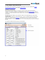
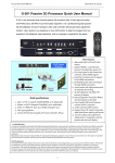
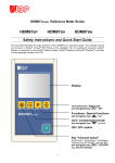
EDID Link
User Manual
Table of Contents
1
EDID LINK
1.1
1.2
2
EDID LINK HARDWARE
SOFTWARE - EDID LINK EDITOR
............3
..........4
..........6
1 EDID LINK
Overview
The EDID Link is a device to manage DVI-EDIDs and communicate these to the graphics card. EDIDs
(Extended Display Identification Data) are used to describe the (preferred) timing of a display device. The
timing is describing the display’s resolution and its sync pixels. It is communicated to the graphic
source via the DVI-cable.
The EDID Link can be used to generate and constantly hold an EDID whenever a display device is not
able to send a correct or the exact needed EDID to the source. In addition the EDID Link will ensure,
that a monitor is simulated even when none is connected to it, or powered down. The EDID Link does
not need any separate power as it receives the voltage from the graphics card.
The EDID Link handles DualLink-DVI-I signals and creates / emulates DVI-EDIDs. Analog signals will be
routed through. The device is not HDCP compliant.
Features
Per default, the EDID Link comes with preinstalled EDIDs and can be used without additional software.
The hardware features are explained in the following chapter. In short, it allows to:
- select an EDID via a preset
- work in transparent mode to route the display device's EDID information to the graphics card
For more advanced users, the EDID Link offers an additional software. In short, it allows to:
- read out a display's EDID or load it from a file
- create an entirely new EDID
- modify EDIDs
- write this EDID to one of the user presets or to a file
3
1.1 EDID LINK HARDWARE
This chapter explains the features of the EDID Link's hardware. The previous chapter offers general
information about the EDID Link whilst the next covers its software features.
Presets
With its two selection knobs, you can select from up to 99 different EDIDs directly. Presets 01-49 are
holding read-only default EDIDs while presets 50-99 can be configured by the user. All EDIDs can be
exported to a file to be used on a different system, such as the Pandoras Box Quad Server with its DVI
Processor.
Preset 00 acts like a “transparent mode” which will route through the EDID coming from the connected
display device. More than that, the last seen, valid EDID is stored to preset 00. Therefore you can
disconnect the display while the graphics card will still see the display’s information. Whenever a
different EDID is transferred into the device, this information will be written into preset 00, even while
emulating another preset at that time.
In order to read out a new EDID, the EDID Link needs to receive 5V either coming from the graphics
card, or the USB-plug. With any 5V input connected, you may read out and store the display’s
information to preset 00 and later on edit it or download it to your computer using the software "EDID
Link Editor".
Usage
Your EDID Link is directly ready to use. You do not need any installation in order to use the default
EDIDs. A list is printed onto the device and is part of the delivered documentation.
- Power down your signal source (e.g. a computer) first.
- Connect the EDID Link’s DVI “in” connector with the included short DVI cable to the graphics card’s
output of your signal source.
- Connect the EDID Link’s DVI “out” connector to your display device (e.g. a monitor).
- Select the desired EDID by rotating the selection knobs.
- Power up your signal source.
The signal source will now receive the EDID adjusted on the EDID Link. You may need to select and
confirm to change to this resolution using the graphics card driver. From now on, there is no direct
connection from the graphic source to the display any longer. Therefore, you may power down the
display without loosing your graphics card settings as the EDID Link is still emulating the device. Even a
loose connection of the DVI cable will not harm the settings any more. When using presets other than
00, you will be able to switch display devices without transferring this information to the source.
It is recommended to power down the complete system before disconnecting a DVI cable.
Rotating the selection knobs while running the system will lead to a disconnect of the attached EDID
Link and the graphics card. It may switch to a not connected state. As long as you turn the knobs, the
EDID Link remains in the disconnected state. After two seconds of not changing the preset, the device
will output the selected EDID. You may need to set the resolution again within your graphics cards
settings or source device settings.
4
LED Codes
The LED next to the USB plug features different LED codes:
Red
blinking
the device is in firmware programming mode
Blue pulsing to magenta every 5s
the device is idle and ready to use
Blue switching once off for 0,5s
the device is used by the software to read from or write to a preset
Important information about internal EDID handling
EDIDs (Extended Display Identification Data) are used to describe the (preferred) timing of a display
device. The timing is describing the display’s resolution and its sync pixels. It is communicated to the
graphic source via the DVI-cable.
A single EDID may feature a list of different timings which can be processed by the monitor. This may
be a combination of “Established Timings”, “Standard Timings” and “Detailed Timings” at the same time.
This gives the user the flexibility to choose from more than one resolution, whenever the native one is not
about to be used.
As this flexibility often leads to not having the desired resolution set within the signal source, the EDID
Link limits all its EDIDs to only one single timing.
Using this fact, the graphics card will be forced to output the exact desired resolution and timing.
Note: All default EDIDs as well as imported or read out ones from any device are changed and
limited to the “First Detailed Timing Descriptor”. Extensions are being cut off as well as soon
as they are stored into the EDID Link.
As preset 00 acts as a transparent mode, you will find the original EDID including all timings and
extensions. Storing this data into a preset will reduce the timing to a single one. How to do this is
explained in the next chapter covering the EDID Link's software.
5
1.2 SOFTWARE - EDID LINK EDITOR
This chapter explains the features of the EDID Link's software. The previous chapters offer general
information about the EDID Link and cover its hardware features.
Installation and Software
Run the “EDID Link Editor Installer” on a Windows operating system and proceed through the
installation. The installer is available on the delivered CD or in the coolux Download-Center. After the
installation you will find the EDID Link Editor software within the Windows start menu and a shortcut on
your Desktop.
The EDID Link Editor software can be used with or without a connected EDID Link to create, edit or
organize EDIDs.
If you like to read an EDID out or write presets onto it, connect your EDID Link via the included USBcable to your computer. Use the USB-driver “coousb-driver v6.0.13.0” (or a newer one) to finish the
hardware installation of the device. The EDID Link is now communicating with your system and ready to
be used.
The software is divided into three sections as pictured below.
6
Menu Bar
File Menu
Use “Load EDID File ...” to load a stored EDID into the Editor. You can then edit and store this EDID to
an EDID Link preset or export it into a file again.
Use “Save EDID File ...” to export the currently displayed EDID timing into a file.
Edit Menu
Use “Read Monitor EDID” to force the EDID Link to read the currently connected EDID (again) and
display it within the Graphical User Interface (GUI). If no valid EDID can be read, all values will equal
zero.
Note: If you want to read out what has already been stored automatically to preset 00 when the monitor
has been attached, you can recall preset 00 without using this menu item.
Use “Initialize Default EDID List” in order to re-initialize the default EDIDs on all presets.
Note: This action will overwrite all user data.
Preset Settings
Use the “EDID Link Preset” numeric box in order to recall the particular preset 00-99 by either clicking
up/down or typing in the desired preset number followed by the return key.
Choosing a preset will read out its content stored within the EDID Link and display it in the "EDID
Description" section.
Check the “Update GUI” check box in order to directly recall content from a preset while changing the
preset number. You may uncheck the check box in order to select a preset without loading its content
(and overriding your changes done in the EDID settings).
Use the “Save to Preset” button in order to store the currently displayed EDID timing into the selected
preset. You may want to uncheck the “Update GUI” check box in order to select a preset you want to
overwrite without loosing your settings entered in the "Detailed Timing" settings below.
EDID Description
The EDID Description shows the content of the “First Detailed Timing Descriptor Block” along with the
“Monitor Name” out of the EDIDs “Descriptor Block 2”.
The displayed information can be edited and stored to the EDID Link or to a file as described above.
7
Detailed Timing
Name
Read out or change the monitor name with a maximum of 13 characters.
PixelClock
This value shows the signal’s PixelClock in MHz.
The maximum value is 330.
Rate Hz
This value shows the signal’s Refresh Rate in Hz when an EDID is loaded. It results
of all other definable settings regarding pixel count and PixelClock.
Res X
This value shows the signal’s active pixel per horizontal line. Active pixels are the
shown ones within a display device and equal the horizontal resolution.
The maximum value is 4095.
Res Y
This value shows the signal’s active lines per image. Active lines are the shown ones
within a display device and equal the vertical resolution.
The maximum value is 4095.
Blank X
This value shows the signal’s total horizontal blanking pixels including (definable) front
porch, (definable) sync width and (resulting) back porch.
The combination of the horizontal active, blanking and border pixels equals the
picture’s horizontal total pixels.
The maximum value is 4095.
Blank Y
This value shows the signal’s total vertical blanking lines including (definable) front
porch, (definable) sync width and (resulting) back porch.
The combination of the vertical active, blanking and border lines equals the picture’s
vertical total lines.
The maximum value is 4095.
H Sync Off
This value shows the signal’s horizontal sync offset (front porch) in pixels.
The maximum value is 1023.
V Sync Off
This value shows the signal’s vertical sync offset (front porch) in lines.
The maximum value is 1023.
H Sync Width
This value shows the signal’s horizontal sync width in pixels.
The maximum value is 1023.
V Sync Width
This value shows the signal’s vertical sync width in lines.
The maximum value is 1023.
H Img Size
This value shows the monitor’s horizontal image size in mm. This information value is
optional and has no influence on the signal processing.
The maximum value is 4095.
V Img Size
This value shows the monitor’s vertical image size in mm. This information value is
optional and has no influence on the signal processing.
The maximum value is 4095.
H Border
This value shows the signal’s horizontal border in pixels.
The maximum value is 255.
V Border
This value shows the signal’s vertical border in lines.
The maximum value is 255.
Interlaced
This check box shows if the signal is interlaced (checked) or progressive
(unchecked).
Sync Signal
Readout or select the desired sync option required by the signal.
Depending on the chosen sync option, there are additional check boxes to be de-/activated.
Stereo Mode
Readout or select the desired Stereo Mode required by the signal.
8