1
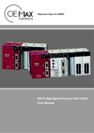
Freescale Semiconductor, Inc. Order this document by MC68306UMAD/AD Microprocessor and Memory Technologies Group MC68306 Freescale Semiconductor, Inc... ADDENDUM TO MC68306 Integrated EC000 Processor User’s Manual September 8, 1995 This addendum to the initial release of the MC68306UM/AD User’s Manual provides corrections to the original text, plus additional information not included in the original. This document and other information on this product is maintained on the AESOP BBS, which can be reached at (800)843-3451 (from the US and Canada) or (512)891-3650. Configure the modem for up to 14.4K baud, 8 bits, 1 stop bit, and no parity. Terminal software should support VT100 emulation. Internet access is provided by telneting to pirs.aus.sps.mot.com [129.38.233.1] or through the World Wide Web at http://pirs.aus.sps.mot.com. 1. Reset and Three-State Outputs In the signal summary tables beginning page 2-3, most outputs which three-state during bus arbitration also three-state during reset. The DRAM control signals in Table 2-3 on page 2-3 are the exception - these signals are three-stated during reset, but periodically drive for refresh cycles to keep DRAM data alive. The DRAM control signals do not drive for refreshes during bus arbitration, and alternate master tenures greater than the refresh period may result in lost refresh cycles. Use pullups as indicated to keep three-stated signals from inadvertently accessing memory during either bus arbitration or reset. 2. Pullup Recommendations The pullup resistor recommendations in the signal summary tables beginning page 2-3 are intended as general guidelines only - the specific values shown can be modified to suit individual applications. The values shown were selected to provide reasonable rise times while remaining within DC IOL drive limits. 3. Halt and Three-State Outputs For section 3.4.3 Halt Operation on page 3-26, the bus interface is in an inactive state during halt. The data bus three-states, and other outputs remain driven. 4. Bus Description Error In Figure 3-27 on page 3-28, the reset time should be 132 clocks minimum. Also, the note that all control signals go inactive is wrong - all bus control signals, address bus, data bus, etc. go to a high impedance state during reset. The address bus on the MC68306 does not go high impedance between bus cycles, as shown in all bus timing diagrams in Section 3. 5. Crystal Oscillator Recommendations Crystals for either the CPU oscillator or the serial module oscillator should be specified for parallel resonant operation, with series resistance less than 80Ω. This document contains information on a product under development. Motorola reserves the right to change or discontinue this product without notice. SEMICONDUCTOR PRODUCT INFORMATION 1995 Motorola, Inc. All Rights Reserved. For More Information On This Product, Go to: www.freescale.com Freescale Semiconductor, Inc. 6. DC Electrical Specifications The DC electrical specifications on page 8-4, section 8.5 have been changed: a) The minimum DC Input Low Voltage is GND - undershoot has been listed as a separate spec of -0.3V. b) The clock inputs EXTAL and X1 are CMOS inputs - Clock Input Low Voltage has been respecified as a function of VDD. c) Pullup, Pulldown, and Output Current specifications have been added. d) Power dissipation has been recalculated for a worst case current drain of 100mA at 5.25V (not 5.0V). DC ELECTRICAL SPECIFICATIONS Characteristic Symbol Min Max Unit VIL GND 0.8 V Clock Input High Voltage (EXTAL, X1) VIHC 0.8*(VCC) VCC V Clock Input Low Voltage (EXTAL, X1) VILC 0 0.2 *VCC V – –0.3 V –50 –10 µA 10 50 µA IOH IOL 8 8 — mA IOH IOL 4 4 — mA PD — 0.525 W Freescale Semiconductor, Inc... Input Low Voltage (except clocks) Undershoot Pullup Current @VIN = 0V HALT, RESET, AS, UDS, LDS, DTACK, BERR, TRST, TMS, TDI Pulldown Current @VIN = VCC TCK Output Current CLKOUT, RAS1–RAS0, CAS1–CAS0, DRAMW, A15/DRAMA14–A1/DRAMA0 Others Power Dissipation f= 16.67 MHz 7. Operating Conditions The following table was omitted from page 8-1: OPERATING CONDITIONS Rating Symbol Min Max Unit 4.75 5.25 V Supply Voltage VCC Input Voltage Vin 0 VCC V Operating Temperature Range TA 0 70 °C Min Max Unit NOTES: 1. Unused input and bidirectional pins must be terminated to a valid logic one or zero level. 8. Maximum Ratings - Input Voltage On page 8-1, the maximum input voltage rating is either 7.0V or VCC+0.3V, whichever is less. 9. New System Interface Specifications The following new electrical specifications have been added. Num. 104 AMODE, IRQx Setup and Hold to RESET Negation 60 — ns 105 Port Pin Setup to AS Asserted, Port Pin Read 30 — ns 105A Port Pin Hold from AS Negated, Port Pin Read 30 — ns UDS, LDS Asserted to Port Pin, Port Write 0 60 ns 106 2 Characteristic MC68306 USER’S MANUAL ADDENDUM For More Information On This Product, Go to: www.freescale.com MOTOROLA Freescale Semiconductor, Inc. 10. Drive Levels and Test Points for AC Specifications The current drive levels and test points for the MC68306 are shown in the revised Figure 8-1 below (page 8-3). 3.75 V 3.75 V CLKOUT 0.85 V 0.85 V A B OUTPUTS(1) VALID OUTPUT n 3.75 V 3.75 V 0.85 V 0.8 V VALID OUTPUT A n+1 B VALID OUTPUT n Freescale Semiconductor, Inc... OUTPUTS(2) C 2.4 V INPUTS(3) 0.6 V 3.75 V 3.75 V 0.8 V 0.8 V VALID OUTPUT n+1 D 2.4 V VALID INPUT 0.6 V C 2.4 V INPUTS(4) 0.6 V D VALID INPUT 2.4 V 0.6 V ALL SIGNALS(5) E F NOTES: 1. This output timing is applicable to all parameters specified relative to the rising edge of the clock. 2. This output timing is applicable to all parameters specified relative to the falling edge of the clock. 3. This input timing is applicable to all parameters specified relative to the rising edge of the clock. 4. This input timing is applicable to all parameters specified relative to the falling edge of the clock. 5. This timing is applicable to all parameters specified relative to the assertion/negation of another signal. LEGEND: A. Maximum output delay specification. B. Minimum output hold time. C. Minimum input setup time specification. D. Minimum input hold time specification. E. Signal valid to signal valid specification (maximum or minimum). F. Signal invalid to signal invalid specification (maximum or minimum). FIgure 8-1. Drive Levels and Test Points for AC Specifications 11. Counter/Timer Mode Clock Source Select Bits In Table 6-10 on page 6-31, the entry under “Clock Source Select Command” for “Crystal or External Clock” with MISC2 = 0 should be “Crystal or External Clock Divided by 16”. MOTOROLA MC68306 USER’S MANUAL ADDENDUM For More Information On This Product, Go to: www.freescale.com 3 Freescale Semiconductor, Inc. 12. Memory Map Error In Table 5-1 on page 5-2, the entry for address FFFFFFF4/5 should be labeled PORT A PINS and PORT B PINS rather than PORT A PIN ASSIGNMENT and PORT B PIN ASSIGNMENT. Note 4 should read “Duplicate of FFFFF7E0–FFFFF7FF”. 13. DIV and MUL Instructions The DIVS and DIVU summaries on page 4-9, and the MULS and MULU summaries on page 4-10 incorrectly show longword (.L) variants. The 68EC306 only supports word sized (.W) operations for these instructions. 14. X1/Clock Addition Freescale Semiconductor, Inc... The last sentence in paragraph 6.2.1 on page 6-4 should read: “If the serial module is not being used at all, the X1/CLK input may be tied to VCC or GND. 15. IP2, OP3 Signal Descriptions On page 6-6, the following paragraphs should be added: 6.2.11 Channel B Receiver Clock/Timer Clock (RxCB/TCLK/IP2) This pin can be used as the channel B receiver clock source, the counter/timer clock source, or as a dedicated parallel input. It can generate an interrupt on change-of-state. 6.2.11.1 RxCB. When used for this function, the received data is sampled on the rising clock edge. 6.2.11.2 Timer Clock. When used for this function, the counter/timer decrements on the rising clock edge. 6.2.11.3 IP2. When used for this function, this signal is a general-purpose input. 6.2.12 Parallel Output (OP3) 6.2.12.1 Counter/Timer Output, Channel B Clock Output. This output can be used as the open-drain activelow counter-ready output, the open-drain timer output, the channel B transmitter 1X-clock output, or the channel B receiver 1X clock output. 6.2.12.2 OP3. When used for this function, this output is controlled by bit three in the DUOP register. 16. Receiver Clock Select Error In Table 6-5 on page 6-25, IP2 can be used as the RxCB clock input. RCS3–RCS0 values 1110 and 1111 are valid for CSRB only, and select IP2–16X and IP2–1X clock sources, respectively. Lack of IP5 prevents use of a 1X transmit clock for the current implementation. 17. Bus Arbitration For specification 37A on page 8-10 (BGACK Asserted to BR Negated) the minimum value must be met to guarantee proper operation. If the maximum value is exceeded, BG may be reasserted. The processor will negate BG and begin driving the bus again if external arbitration logic negates BR before asserting BGACK. Figure 8-6 on page 8-10 shows timing for 2-wire bus arbitration (BGACK not used). FIgure 8-7 on the following page shows timing for 3-wire bus arbitration (BGACK used). 18. Omission of Control Bit Definition In paragraph 7.3 on page 7-4, the following sentences should be added immediately before Table 7-1: “All control bits with overbars, and HiZ, are active low. Their respective output bits are enabled when a zero is shifted into the control bit. The other control bits are active high.” 19. HiZ Control Function In table 7-2 on page 7-5, the HiZ control function in the boundry scan definition (bit 67) should be shown as active low (HiZ) rather than active high (HiZ.) 4 MC68306 USER’S MANUAL ADDENDUM For More Information On This Product, Go to: www.freescale.com MOTOROLA Freescale Semiconductor, Inc. 20. ACKx Assertion Time IACKx is shown asserted too early in Figure 8-5 on page 8-9. The figure below shows IACKx assertion time (spec 70) correctly referenced to the rising edge of state S4. READ S0 S1 S2 WRITE S3 S4 S5 S6 S12 S13 S14 S15 S16 S17 S18 (NOTE 1) CLKOUT 65 65 FC2–FC0, A23–A0 AS (NOTE 1) 63 62 62 Freescale Semiconductor, Inc... LDS / UDS 63 R/W 66 61 61A 61 61A 64 64 CS 69 70 IACKx 70A IN DATA OUT 68 12A 9A 67 OE 9A UW, LW 12A NOTE: THE WRITE CYCLE ILLUSTRATED IS PART OF A TEST AND SET INSTRUCTION. Figure 8-5. Chip Select and Interrupt Acknowledge Timing Diagram 21. Clock Output Timing The current drive levels and test points for the MC68306 input and output clocks are shown in the revised Figure 8-2 below (see page 8-5.) 1 3 2 4.0 V EXTAL 4.0 V 2.5 V 1.0 V 1.0 V 4.0 V 2.5 V 4.0 V 1.0 V 5 4 1A 1 1A 2A 3.75 V CLKOUT 3A 3.75 V 1.5 V 0.85 V 3.75 V 1.5 V 0.85 V FIgure 8-2. Clock Output Timing MOTOROLA MC68306 USER’S MANUAL ADDENDUM For More Information On This Product, Go to: www.freescale.com 5 Freescale Semiconductor, Inc. 22. DRAM Address Hold Time Specification 13A below has been added to the AC electrical specifications on page 8-5. A revised figure 8-8 from page 8-13 shows the new specification (address hold from AS/UDS/LDS negate near state S7). S0 S1 S3 S2 S5 S4 S7 S6 CLKOUT FC0–FC2 82 A15/DRAMA 14– A1/DRAMA 0 73 87 76 AS 13A Freescale Semiconductor, Inc... UDS, LDS R/W UW, LW OE DTACK 71A 89 75 D15–D0 74 DRAMW 89A 71 80 78 RAS 80 81 88 CAS 90 90 84 86 16.67 MHz Num 13A Characteristic AS, LDS, UDS Negated to Address Invalid, DRAM Cycle Min Max Unit 0 — ns Figure 8-8. DRAM Timing – 0-Wait Read, No Refresh 23. Interrupt Level Description Error In paragraph 6.1.4, the last sentence on page 6-3 should read “When an interrupt at this level is acknowledged, the serial module is serviced before the external IRQx of the same level.” 24. Bus Timeout Period Register Address Error In paragraph 5.2.3 on page 5-4, the bus timeout period register address should be “FFFFFFFD”. 25. Chip Select Configuration Register Reset State Error In paragraph 5.2.6.2 on page 5-10, the reset value of CS0 bit 15 (CSR-Chip Select Read enable) is one, not zero. 6 MC68306 USER’S MANUAL ADDENDUM For More Information On This Product, Go to: www.freescale.com MOTOROLA Freescale Semiconductor, Inc. 26. DRAM Refresh Cycles The specifications for DRAM refresh timing in the AC Specifications on page 8-12 and in Figure 8-10 on page 8-14 referenced the wrong clock edges. Corrected specifications and figures are shown below. AC ELECTRICAL SPECIFICATIONS—DRAM 16.67 MHz 0-Wait Freescale Semiconductor, Inc... Num. Characteristic 1-Wait Min Max Min Max Unit 95 CLKOUT High to CASx Asserted (Refresh Cycle) 0 20 0 20 ns 96 CLKOUT Low to CASx Negated (Refresh Cycle) 0 20 0 20 ns 98 CASx Asserted to RASx Asserted (Refresh Cycle) 20 60 20 60 ns 99 CLKOUT Low to RASx Asserted (Refresh Cycle) 0 30 0 30 ns 100 CLKOUT High to RASx Negated (Refresh Cycle) 0 25 0 25 ns 102 DRAMW High to RASx Asserted (Refresh Cycle) 20 60 20 60 ns CLKOUT 96 102 DRAMW 100 99 101 RAS 80 103 95 CAS 90 97 98 a. 0 - Wait State CLKOUT 102 DRAMW 103 100 99 101 RAS 80 95 CAS 96 90 97 98 b. 1 - Wait State Figure 8-10. DRAM Timing Refresh MOTOROLA MC68306 USER’S MANUAL ADDENDUM For More Information On This Product, Go to: www.freescale.com 7 Freescale Semiconductor, Inc. 27. DRAM Timing for 1-Wait Access Figure 8-9 on page 8-14 is missing a wait state - see the revised figure below. Spec 13A has also been added to this figure. S0 S1 S3 S2 W W S4 S5 S6 S7 CLKOUT FC0–FC2 83 A15/DRAMA 14– A1/DRAMA 0 73 87 77 AS 13A Freescale Semiconductor, Inc... UDS, LDS R/W UW, LW OE DTACK 89 75 D15–D0 74 89A 94 DRAMW 72 80 78 RAS 80 81 CAS 90 88 93 85 90 86 Figure 8-9. DRAM Timing – 1-Wait Write, No Refresh 28. Pin Assignment Orientation Error The pin assignment diagram of the 144-Lead Thin Quad Flat Pack (TQFP) on page 9-3 of section 9.2 should be rotated 90 degrees counter clockwise (including pins.) As a result, the pin one dot should be in the lower left hand corner. The part number should still be horizontally displayed in the drawing. All TQFP parts are marked such that pin one is in the lower left hand corner when viewing the part with the markings oriented normally. 29. Package Dimensions Diagram Error The 132-pin package diagram on page 9-4 shows 32 pins on a side. There are actually 33 pins on a side. The specifications for the case size and pin spacing are correct. 8 MC68306 USER’S MANUAL ADDENDUM For More Information On This Product, Go to: www.freescale.com MOTOROLA Freescale Semiconductor, Inc. J 128 X J1 AC S AC G -X- X=L,M,OR N S1 A A1 -N- VIEW AB VIEW AB PIN 1 IDENT P1 V1 -M- BASE METAL ÇÇÇÇ ÍÍÍÍ ÍÍÍÍ ÇÇÇÇ ÍÍÍÍ B E Freescale Semiconductor, Inc... P -L- AA V B1 (D) D2 AA E1 WITH PLATING SECTION AC-AC ) " # ) " " ) " " 2X " " 4X ) " 2X 4 X 33 TIPS 4X C C2 # -TC1 F 132 PL # ) R R1 " " #" " #! ! " ( #! " "" # $ !#!$" & !#!$" ! "" " ! "" " #$ )) " # # # $!" " &! " '# ( #$" )) )) )) # #! &! #! " '# ( # #$ )) "" $ % # #! # "# #$ )#) "" # #! # #$ )) " " # $ ! !#!$"" ! !#!$" " # $" # &# # ' -HK1 GAGE PLANE U W K 132 X D # ) " 01 " SECTION AA-AA " " " " " " " " " " ! " " ! " " " " " " " " " " " " " " " ! " " CASE 831A-02 ISSUE B MOTOROLA MC68306 USER’S MANUAL ADDENDUM For More Information On This Product, Go to: www.freescale.com 9 Freescale Semiconductor, Inc... Freescale Semiconductor, Inc. Motorola reserves the right to make changes without further notice to any products herein. Motorola makes no warranty, representation or guarantee regarding the suitability of its products for any particular purpose, nor does Motorola assume any liability arising out of the application or use of any product or circuit, and specifically disclaims any and all liability, including without limitation consequential or incidental damages. "Typical" parameters can and do vary in different applications. All operating parameters, including "Typicals" must be validated for each customer application by customer's technical experts. Motorola does not convey any license under its patent rights nor the rights of others. Motorola products are not designed, intended, or authorized for use as components in systems intended for surgical implant into the body, or other applications intended to support or sustain life, or for any other application in which the failure of the Motorola product could create a situation where personal injury or death may occur. Should Buyer purchase or use Motorola products for any such unintended or unauthorized application, Buyer shall indemnify and hold Motorola and its officers, employees, subsidiaries, affiliates, and distributors harmless against all claims, costs, damages, and expenses, and reasonable attorney fees arising out of, directly or indirectly, any claim of personal injury or death associated with such unintended or unauthorized use, even if such claim alleges that Motorola was negligent regarding the design or manufacture of the part. Motorola and are registered trademarks of Motorola, Inc. Motorola, Inc. is an Equal Opportunity/Affirmative Action Employer. Literature Distribution Centers: Literature Distribution Centers: USA/EUROPE: Literature Distribution; P.O.20912, Box 20912, Arizona 85036 USA: MotorolaMotorola Literature Distribution; P.O. Box Arizona 85036. JAPAN: Nippon Motorola Ltd.; 4-32-1, Nishi-Gotanda, Shinagawa-ku, Tokyo 141Blakelands, Japan EUROPE: Motorola Ltd.; European Literature Centre; 88 Tanners Drive, Milton Keynes, MK14 5BP, England. JAPAN: NipponMotorola Motorola Ltd.; 4-32-1, Nishi-Gotanda, Japan. ASIA-PACIFIC: Seminconductors H.K. Ltd.; SiliconShinagawa-ku, Harbour Center,Tokyo No. 2 141 Dai King Street, Tai Po Industrial Estate, ASIA-PACIFIC:Tai Motorola H.K. Ltd.; Silicon Harbour Center, No. 2 Dai King Street, Tai Po Industrial Estate, Po, N.T.,Semiconductors Hong Kong SEMICONDUCTOR PRODUCT INFORMATION For More Information On This Product, Go to: www.freescale.com