1
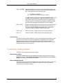
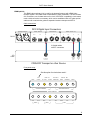
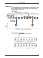
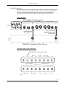
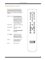
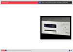
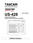
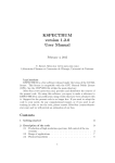
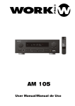
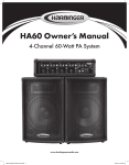
DCC2 DIGITAL CONTROL CENTER
USER MANUAL
Version 1.8
DCC2 User Manual
DCC2 Digital Control Center
The DCC2 is a stereo D/A converter with built-in pre-amplifier that evolved from EMM
Labs’s acclaimed converter and pre-amplifier systems that have been used worldwide in
professional recording studios to master some of the finest recordings in both CD and
SACD releases.
The D/A section provides conversion from a wide variety of digital input formats to analog
audio, and the pre-amp section provides 2 analog inputs and 1 analog output. There is an
additional analog output that bypasses the pre-amp section.
Features
•
2-channel conversions:
• from PCM (44.1kHz, 48kHz, 88.2kHz, 96kHz) to analog
• from DSD to analog
•
Supported digital input formats:
• AES/EBU (2 connectors and 1 connector)
• SPDIF (Coax)
• Optical TOSLink
• PCM over optical ST glass (AES formatted)
• RAW DSD
• SDIF-3 (DSD)
• EMM OptiLink
•
Analog Inputs
• Balanced on XLR (switchable to be unbalanced)
• Unbalanced on RCA
•
Analog outputs
• Balanced on XLR for signals after pre-amp
• Unbalanced on RCA for signals after pre-amp
• Balanced on XLR for signals bypassing pre-amp
• Unbalanced on RCA for signals bypassing pre-amp
•
Analog output impedances
• 100Ω balanced, 50Ω unbalanced
Note: XLR analog inputs and outputs are balanced with pin 2 hot, pin 3 cold and pin 1
ground.
•
Power supply
• Power factor corrected
• Factory set to 100V or 115V or 230V, 50/60Hz
• Power consumption: 60W
•
Remote control: Infrared
•
Dimensions W x D x H: 435 x 400 x 92mm
•
Weight: 11kg
2
L
R
2
BAL
UNBAL
R
COAX
RCA
L
TOS
S/PDIF INPUTS
ANALOG LINE INPUTS
PUSH
PUSH
XLR
PUSH
PUSH
AES/EBU INPUTS
emm Labs
ST
R
BNC
R
BNC
DSD
L
IN
ST
ANALOG LINE OUTPUT
L
DSD INPUTS
RCA
PCM
COAX
OUT
IN
ST
L
REMOTE
SYSTEM
ANALOG PREAMP OUTPUT
R
OUT
TOS
ANALOG OUTPUT
WORD CLOCK I/O
AES
INPUT SELECT
BASE FS
POLARITY
DIGITAL BW
44.1 KHZ 48 KHZ INVERTED WIDE
NARROW MUTE
CLOCK CONTROL
EXT
CLOCK
ANLG
XLR
LOCK
RESET
DCC2
2000
SERIAL
MADE IN CANADA
MODEL
emmLabs
DCC
meitnerdesign
85 - 260 V
50 / 60 Hz
100 W MAX
DCC2 User Manual
3
DCC2 User Manual
Function Switches and Indicators
Power
The main power switch is on the back of the unit. The chrome power button on the front
is a momentary switch that toggles the operation between power on and power save
mode every time the user pushes it. During the power save mode the remote control and
all front panel functions become inactive.
Clock Control Section
LOCK:
This indicator is lit when the unit detects valid clock at the selected
digital audio input. For normal operation with digital audio inputs this
indicator has to be lit or else all audio outputs will be muted. For
normal operation with analog audio inputs this indicator will stay off
and all audio outputs are unmuted.
EXT CLOCK:
Selects external clock input when lit. The actual clock input is then
determined by the selected digital input. This switch controls the
“Master” and “Slave” operation as explained in more depth later in
this manual. For Master operation this switch has to be turned off,
and for Slave operation it has to be turned on.
44.1kHz / 48kHz:
These buttons select the base frequency for the selected digital
audio input. For instance, for all digital inputs with sample
frequencies of 44.1kHz or 88.2kHz the switch 44.1kHz has to be
selected, for all digital inputs with sample frequencies of 48kHz or
96kHz the switch 48kHz has to be selected.
Analog Output Section
POLARITY:
When this switch is lit the polarity of all analog outputs is inverted.
WIDE / NARROW: These switches are only active when a digital audio input source is
selected and are inactive for analog input sources. When NARROW
bandwidth is selected the analog outputs are lowpass filtered to limit
the amount of signal content above 30kHz. The WIDE mode selects
a much wider bandwidth and should be used in most cases.
MUTE:
When lit all outputs are muted. Pushing the button again unmutes
the outputs.
Analog, DSD and PCM Input Sections
These 8 switches select the input source with associated clock.
XLR:
Balanced analog line input from the XLR connectors. Optionally this
input can be configured for unbalanced inputs with a toggle switch on
the rear panel besides the XLR connectors.
RCA:
Unbalanced analog line input from the RCA connectors.
DSD - BNC:
DSD digital input from the BNC connectors. Either RAW-DSD or
SDIF-3 can be used (auto detection).
DSD – ST:
EMM OptiLink for direct connection to EMM Labs transport.
4
DCC2 User Manual
PCM – AES/EBU:
Selects PCM digital input from the XLR inputs. Sample rates up to
96kHz are supported. For sample rates of 88.2kHz and 96kHz there
are 2 configurations that are commonly used:
1) one cable for 2 channels
2) 1 cable for each channel (total of 2 cables)
If 1 cable is used it needs to be plugged into AES/EBU INPUT 1, and
if 2 cables are used both inputs 1 and 2 have to be connected. In
either case the DCC2 will automatically detect if the digital input is
running at 44.1kHz or 88.2kHz (resp. at 48kHz or 96kHz) provided
the correct base frequency is selected (44.1kHz resp. 48kHz).
PCM – COAX:
Selects PCM digital input from Coax (RCA) input. Sample rates up to
96kHz are supported. Make sure to select the base frequency of
44.1kHz for 44.1kHz and 88.2kHz sample rates, or select base
frequency of 48kHz for 48kHz or 96kHz sample rates.
PCM – TOS:
Same as for PCM – COAX, but input is from optical TOSLink.
PCM – ST:
same as for PCM – COAX, but input is for optical ST glass.
Volume Control
The wheel on the front panel controls the volume on the analog pre-amp outputs. As the
wheel is turned clockwise the volume increases and the displayed numbers increase,
whereas when the wheel is turned anti-clockwise the volume decreases and the
displayed numbers decrease. The displayed numbers range from 00 (volume is set to
lowest) to 99 (volume is set to highest).
Connecting Analog Outputs
The DCC2 has 2 separate analog stereo outputs:
ANALOG LINE OUTPUT
This output bypasses the built-in pre-amplifier and volume control of the DCC2 and is
always set to full level. Be careful and do NOT connect this output to your amplifier
directly, but rather to your separate pre-amplifier.
ANALOG PREAMP OUTPUT
This output is from the internal pre-amplifier and is controlled by the volume control. This
should be connected directly to your amplifier. However, be careful to first turn the
volume down (low number in display).
5
DCC2 User Manual
Basic Operations and Input Connections
Memory after powerup and during operation
After about 10 seconds after no button has been pushed and the volume has not been
changed, the DCC2 memorizes its momentary setup in permanent memory for later
retrieval after the next powerup. It will be recalled immediately after the unit is turned on.
Each individual input selection will keep its last configuration and volume setting before
powerdown.
During normal operation each input selection will immediately memorize its configuration
and volume setting so that switching between different sources with different
configurations can be accomplished with a single button without having to adjust any
other settings again.
Note: Each input selection has its own volume setting that gets memorized when
changing inputs.
Wired remote control
On the rear panel you can find a DIN 9-pin connector for serial remote control (see
Appendix A for more details).
Reset during operation
Should there ever be a problem with the operation of the DCC2 you can push the Reset
button on the rear panel to restart the internal software. This has the same effect as
cycling the power off – on. , i.e. the DCC2 returns to the state that was last stored.
Analog Input
The pre-amp section of the DCC2 can be used with 2 analog inputs on the back of the
unit: XLR or RCA as shown in below figure.
PUSH
PUSH
UNBAL
R
XLR
L
BAL
R
RCA
L
ANALOG LINE INPUTS
The XLR inputs can be configured as balanced or unbalanced (single ended) with the
toggle switch on the back right next to the analog XLR input connectors. For unbalanced
connections pin 2 of the XLR connector is assumed to be hot and pin 1 ground.
6
DCC2 User Manual
Clock Master and Clock Slave Modes
The DCC2 provides 2 basic ways for how to connect an audio source to it, such as a CD
transport: clock master and clock slave modes. Master / slave is in reference to who
provides the clock signal to the D/A conversion process and who receives an external
clock as a guide signal to lock to.
In clock master mode the DCC2 generates and provides the clock to the D/A conversion
process and also to the CD transport. Of course, for this the CD transport has to be
equipped with an external clock input. If no such connection is available then the only
way to connect the transport to the DCC2 is in clock slave mode. The clock master mode
will generally provide better sonic performance over the clock slave mode as clock jitter is
minimized.
In clock slave mode the transport provides the main clock and the DCC2 will use it as a
reference to lock to. For best results you should operate the DCC2 in clock master mode
whenever possible.
The following paragraphs explain master and slave setups in detail for every individual
digital source input of the DCC2.
AES/EBU input
In cases where the sample rate is either 44.1kHz or 48kHz there will be only 1 cable with
XLR connectors for the audio data. Connector 1 on the back of the DCC2 has to be used.
In cases where the sample rate is either 88.2kHz or 96kHz there are two possible
topologies depending on how the source operates:
•
•
1 single cable for 2 channels
2 individual cables for 1 channel each
Again, if only 1 cable is used it has to be plugged into connector 1 on the DCC2. For the
2 cable topology both connectors on the DCC2 have to be used. The DCC2 will
automatically detect the correct topology and decode the audio data accordingly.
For master clock operation a cable with BNC connectors needs to be connected
according to below picture. For clock slave operation this cable is not necessary.
7
DCC2 User Manual
Cable connections for AES/EBU input:
DCC2 Digital Input Connectors
AES/EBU INPUTS
PUSH
1
PUSH
S/PDIF INPUTS
DSD INPUTS
WORD CLOCK I/O
2
COAX
TOS
ST
L
BNC
R
IN
IN
OUT
OUT
DCC2
BNC clock cable
(required only for
clock master mode)
AES/EBU cable with XLR connectors
CD
Deck
BNC
CLOCK
IN
AES/EBU
DATA OUT
CD/SACD Transport or other Source
Front panel setup:
Set this option for clock slave mode !
EXT
LOCK
CLOCK
BASE FS
44.1 KHZ
48 KHZ
POLARITY
INVERTED
CLOCK CONTROL
DIGITAL BW
WIDE
NARROW
MUTE
ANALOG OUTPUT
INPUT SELECT
XLR
RCA
ANLG
BNC
ST
DSD
AES
COAX
TOS
ST
PCM
8
DCC2 User Manual
EMM OptiLink
This EMM Labs proprietary link is used for the best performance with a EMM Labs
transport system. The cables used are standard ST glass (multimode). The link consists
of 2 connections, one for data and one for clock. If the DCC2 is operated in clock master
mode a third connection is necessary, which can be established with a ST glass optical
cable as well to maintain the galvanic separation between transport and DCC2.
Cable connections:
DCC2 Digital Input Connectors
PUSH
1
PUSH
DSD INPUTS
S/PDIF INPUTS
AES/EBU INPUTS
WORD CLOCK I/O
2
COAX
TOS
ST
L
BNC
IN
R
OUT
IN
OUT
OPTICAL
CLOCK
OUT
OPTICAL
CLOCK
IN
DCC2
3 Optical cables
with ST connectors
CD
Deck
ST OPTICAL
DATA OUT
CD/SACD Transport or other Source
Front panel setup:
Set this option for clock slave mode !
EXT
LOCK
CLOCK
BASE FS
44.1 KHZ
48 KHZ
POLARITY
INVERTED
CLOCK CONTROL
DIGITAL BW
WIDE
NARROW
MUTE
ANALOG OUTPUT
INPUT SELECT
XLR
RCA
ANLG
BNC
ST
DSD
AES
COAX
TOS
ST
PCM
9
DCC2 User Manual
Coax (SPDIF) input
This link can operate for sample frequencies up to 96kHz. The DCC2 detects the correct
frequency and adjusts automatically. Also with this link the DCC2 can be operated in
either clock master or clock slave mode.
Cable connections:
DCC2 Digital Input Connectors
AES/EBU INPUTS
PUSH
1
PUSH
S/PDIF INPUTS
DSD INPUTS
WORD CLOCK I/O
2
COAX
TOS
ST
L
BNC
R
IN
IN
OUT
OUT
DCC2
BNC clock cable
(required only for
clock master mode)
Coax cable with
RCA connectors
CD
Deck
BNC
CLOCK
IN
COAX
DATA OUT
CD/SACD Transport or other Source
Front panel setup for clock master mode:
Set this option for clock slave mode !
EXT
LOCK
CLOCK
BASE FS
44.1 KHZ
48 KHZ
POLARITY
INVERTED
CLOCK CONTROL
DIGITAL BW
WIDE
NARROW
MUTE
ANALOG OUTPUT
INPUT SELECT
XLR
RCA
ANLG
BNC
ST
DSD
AES
COAX
TOS
ST
PCM
10
DCC2 User Manual
TOSLink input
Also with this link the DCC2 can be operated in either clock master or clock slave mode.
Cable connections:
DCC2 Digital Input Connectors
AES/EBU INPUTS
PUSH
1
PUSH
S/PDIF INPUTS
DSD INPUTS
WORD CLOCK I/O
2
COAX
TOS
ST
L
BNC
IN
R
OUT
IN
OUT
DCC2
BNC clock cable
(required only for
clock master mode)
Optical TOSLink cable
CD
Deck
BNC
CLOCK
IN
TOSLINK
DATA OUT
CD/SACD Transport or other Source
Front panel setup for clock master mode:
Set this option for clock slave mode !
EXT
LOCK
CLOCK
BASE FS
44.1 KHZ
48 KHZ
POLARITY
INVERTED
CLOCK CONTROL
DIGITAL BW
WIDE
NARROW
MUTE
ANALOG OUTPUT
INPUT SELECT
XLR
RCA
ANLG
BNC
ST
DSD
AES
COAX
TOS
ST
PCM
11
DCC2 User Manual
AES on ST glass input
Also with this link the DCC2 can be operated in either clock master or clock slave mode.
In master mode an optical cable can be used for the clock connection between DCC2
and your transport instead of a BNC cable. This will keep the DCC2 galvanically
separated from the transport. But a BNC cable for the clock can also be used.
Cable connections:
DCC2 Digital Input Connectors
AES/EBU INPUTS
PUSH
1
PUSH
DSD INPUTS
S/PDIF INPUTS
WORD CLOCK I/O
2
COAX
TOS
ST
L
BNC
R
IN
OUT
IN
OUT
DCC2
Optical clock cable
(required only for clock
master mode)
Optical cable with
ST connectors
CD
Deck
OPTICAL
CLOCK
IN
ST OPTICAL
DATA OUT
CD/SACD Transport or other Source
Front panel setup for clock master mode:
Set this option for clock slave mode !
EXT
LOCK
CLOCK
BASE FS
44.1 KHZ
48 KHZ
POLARITY
INVERTED
CLOCK CONTROL
DIGITAL BW
WIDE
NARROW
MUTE
ANALOG OUTPUT
INPUT SELECT
XLR
RCA
ANLG
BNC
ST
DSD
AES
COAX
TOS
ST
PCM
12
DCC2 User Manual
Infrared Remote Control
The remote control included with the DCC2
provides many functions for the EMM Labs
CDSD transport system as well. The functions
that are relevant to the DCC2 specifically are
highlighted in blue rectangles in the drawing on
the right.
DISPLAY – DCC2: This function toggles the
front panel display on the
DCC2 on and off. When off
and pushing any button on
the remote or front panel or
adjusting the volume will
turn the display on for about
3 seconds and then turn it
off again automatically.
ANALOG XLR:
This selects the analog XLR
input
ANALOG RCA:
This selects the analog
RCA input
DIGITAL:
This selects the digital input
that was last chosen via the
front panel.
VOLUME
PHASE:
MUTE:
:
DCC2
CDSD
DISPLAY
2
3
4
5
6
7
8
9
0
REPEAT
MODE
PLAY
PAUSE
STOP
XLR
INPUT
RCA
DIGITAL
ANALOG
VOLUME
PHASE
MUTE
This adjusts the volume
setting up or down. When
pressed for more than 3
seconds the volume will
start scrolling automatically.
Toggles the phase of the
audio signal between
normal and inverted.
emm Labs
Mutes all outputs
13
DCC2 User Manual
Specification
Output Line Level with 0dBfs signal on AES/EBU inut
XLR balanced:
RCA unbalanced:
+12.55dBu / +10.35dBv / +3.3V
+8.1dBu / +5.95dBv / +1.98V
Pre-amp Output Level with 0dBfs signal in AES/EBU input
Max. volume (99)
XLR balanced: +18.4dBu / +6.47V
RCA unbalanced: +13.95dBu / +3.866V
Volume level 87 sets the pre-amp output level the same as the line level
Warranty
EMM Labs warrants the DCC2 product against defects in material and workmanship
under normal use and service for a period of time specified by the product’s serial
number from the date of first delivery to the owner. The warranty time period is 5 years
limited to the original owner.
EMM Labs will pay for return shipping charges back to the owner when the product is
sent to EMM Labs within the first 90 days after purchase. Otherwise, owner will be
responsible for all shipping charges to and from EMM Labs.
For all warranty claims, a copy of the original invoice must accompany the product.
Opening the product or modifying it in any way by the owner, including but not limited to
cryogenic treatment, will void any warranty.
Please contact EMM Labs ([email protected]) for RMA number and shipping
instructions before shipping any product to EMM Labs.
EMM Labs products are sold worldwide through authorized dealers with restricted
territories. If any EMM Labs product is purchased from non-authorized dealers or from a
dealer selling outside his / her authorized territory all warranties will be void.
14
DCC2 User Manual
Appendix A: Serial Remote Control (RS-232)
The DCC2 is equipped with a 9-pin RS-232 connector for system remote control via a
serial cable (not provided by EMM Labs). The cable should be non-crossed for
connections between a PC and the DCC2. The parameters and settings for this link are:
•
•
•
•
•
19,200 baud
8 bits
1 stop bit
no flow control
no parity bit
Commands to DCC2
All commands sent to the DCC2 consist of 3 ASCII characters followed by a <CR>.
Repeating a <CR> will repeat the last command sent. This feature can be used to adjust
the volume of the DCC2 over a wide range. Received commands are not stored in a
stack and, therefore, need to be sent in intervals of at least 30ms to allow enough time for
the DCC2 to execute a command before receiving the next one.
Char 0
Char 1
Char 2
Char 0
<CR>
>30ms
mut
wbw
nbw
pol
48k
44k
clk
pst
tos
cox
aes
dst
bnc
rca
xlr
don
dof
pon
pof
vup
vdn
Toggles mute on / off
Select wide bandwidth for digital audio playback
Select narrow bandwidth for digital audio playback
Toggles polarity of all analog outputs inversed / normal
Selects 48kHz base sample frequency
Selects 44.1kHz base sample frequency
Toggles external clock selection on / off
Selects PCM input on ST glass connectors
Selects PCM input on TOSLink connector
Selects PCM input on coax connector
Selects PCM input on AES/EBU connectors
Selects DSD input on ST glass connectors
Selects DSD input on BNC connectors
Selects analog input on RCA connectors
Selects analog input in XLR connectors
Turns front panel display on
Turns front panel display off (unit keeps operating)
Turns power on from standby
Turns DCC2 into standby operation
Moves volume up by 1 step (repeat only <CR> to move multiple steps)
Moves volume down by 1 step (repeat only <CR> to move multiple steps)
15
DCC2 User Manual
Status info from DCC2
The DCC2 sends back 4 Bytes terminated with a <CR> whenever any status changes.
Byte 0
Byte 0
Byte 1
Byte 2
Byte 3
Byte 4
bit 0
bit 1
bit 2
bit 3
bit 4
bit 5
bit 6
bit 7
bit 0
bit 1
bit 2
bit 3
bit 4
bit 5
bit 6
bit 7
Byte 1
Byte 2
Byte 3
<CR>
Volume ones in ASCII
Volume tens in ASCII
Status of Analog XLR input (0 when selected)
Status of Analog RCA input (0 when selected)
Status of DSD input on BNC (0 when selected)
Status of DSD input on ST glass (0 when selected)
Status of PCM input on AES/EBU (0 when selected)
Status of PCM input in Coax (0 when selected)
Status of PCM input on TOSLink (0 when selected)
Status of PCM input on ST glass input (0 when selected)
0 when clock is locked
0 when external clock is selected
0 when 44.1kHz selected as base sample frequency
0 when 48kHz selected as base sample frequency
Status of polarity of analog ouputs (0 when inverted)
Status of wide bandwidth selection (0 when selected)
Status of mute (0 when muted)
1 when in Standby operation
<CR> (x0D)
16