1
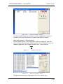
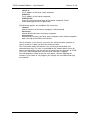
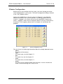
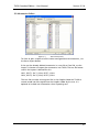
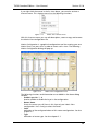
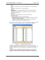
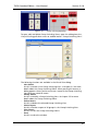
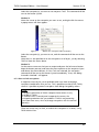
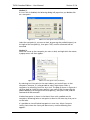
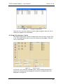
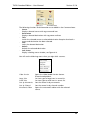
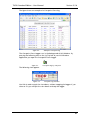
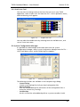
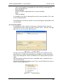
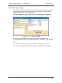
er
VikinX User Manual
THOR
Standard Edition
network-electronics.com
Rev. 3.5.6
THOR Standard Edition – User Manual
Version 3.5.6
Network Electronics ASA
Thorøya
P.O. Box 1020
Sandefjord, Norway
Phone: +47 33 48 99 99
Fax: +47 33 48 99 98
E-mail: [email protected]
www.network-electronics.com
Service Phone: +47 90 60 99 99
Revision history
Current revision of this document is the uppermost in the table below.
Revision Replaces
3.5.6
3.5
3.5
3.0
3.0
2.9
2.0
1.95
1
0
2.9
2.0
1.95
1
0
-
Date
Change description
2007-10-30 New front page and removed old logo.
Updated to reflect changes in THOR structure and
23/06/05
software release 3.5.
24/11/04 Updated to reflect SW release 3.0
24/02/04 Updated to reflect SW release 2.9
01/06/02 Updated to reflect SW release 2.00
05/04/02 Updated to reflect SW release 1.95
25/09/01 Updated and expanded to include User Guidance
02/02/01 Initial Revision
2
THOR Standard Edition – User Manual
Version 3.5.6
Contents
Revision history............................................................................... 2
Definitions, Acronyms and Abbreviations...........................................................4
1 Introduction ................................................................................ 5
1.1 THOR – Router Management System features .............................................5
1.2 System Requirements ..................................................................................7
2 Installation................................................................................... 8
2.1 Installation from CD-ROM ...........................................................................8
2.2 Installation from WEB ..................................................................................8
2.3 THOR file structure ......................................................................................9
3 Main program ........................................................................... 10
3.1 THOR Toolbar Menu .................................................................................10
3.2 THOR Pull Down Menus ............................................................................11
4 Communication settings............................................................ 16
4.1 First time Start-up......................................................................................16
4.2 Communication Settings ...........................................................................16
4.2.1 Compact Router Serial Interface
17
4.2.2 Modular Router Interface
19
4.2.3 LAN Multi User Interface
20
5 Router Configuration ................................................................. 24
5.1 Router Settings ..........................................................................................26
5.2 Mnemonics Editor .....................................................................................27
5.3 UniPro Configuration.................................................................................29
5.4 Virtual Router Mapping .............................................................................30
5.5 Group Configuration .................................................................................33
5.6 Matrix View Configuration.........................................................................35
5.7 Matrix Group View Configuration..............................................................40
6 Router Control........................................................................... 44
6.1 Matrix Control...........................................................................................44
6.1.1 How to set crosspoints
44
6.1.2 How to lock crosspoints
45
6.2 Drag & Drop Router Control .....................................................................47
6.2.1 How to set crosspoints
49
6.2.2 How to lock crosspoints
50
6.2.3 Sorting and Searching
50
6.3 Virtual Router Control................................................................................53
7 Salvo Executer ........................................................................... 54
8 User Manager............................................................................ 59
3
THOR Standard Edition – User Manual
Version 3.5.6
9 Useful Tools............................................................................... 61
9.1 Crosspoint Logging ...................................................................................61
9.2 Universal Control Panel Tools (UniPro) ......................................................63
9.3 Configuration Utilities................................................................................64
9.3.1 Change Data Directory
64
9.3.2 Grafic Icon Tool
65
9.4 System Configuration Manager .................................................................65
9.5 Customize Menu .......................................................................................66
9.6 Product Key Manager ................................................................................67
10 Troubleshooting – Before calling Network Support .................. 68
10.1 User Manual Reference ............................................................................68
10.2 Creating Support Email ...........................................................................69
Definitions, Acronyms and Abbreviations
GUI
RMS
Graphical User Interface
Router Management System
4
THOR Standard Edition – User Manual
Version 3.5.6
1 Introduction
This document describes how to install and use the THOR – Router
Management System, Version 3.5.
1.1 THOR – Router Management System features
THOR represents the latest generation router control software from Network
Electronics ASA. THOR can be extended with feature packs. It includes the
following software modules:
Router Configuration
- Auto detection of routers connected to the master computer.
- Configurable parameters for each router switchers.
- Configurable tag names and graphic icons for input channels.
- Configurable tag names and graphic icons for output channels.
Matrix Views
- Matrix views with 4 levels.
- Possible to save an unlimited number of matrix view configurations.
- Scrollable and sizeable Matrix View.
- Matrix Group Views
Salvo Executer
- Multi level executable salvo commands to all routers.
- Possibility to save an unlimited number of salvos.
- Graphical salvo editor for creating salvos.
Drag and Drop Router Control
- Icon based multilevel routing switcher control.
- Graphical router control by drag and drop.
- Source copy function by easy destination-to-destination drop.
- Selectable icon or list view for sources and destinations.
- Search on name function.
- Virtual Router Mapping, switching different router levels simultaneously.
User Management
- Administrate all your THOR user accounts.
- User by user locking.
User Tools
- Crosspoint logging
- Configuration Manager, create and restore backups of configuration files
Router Communication
- Serial Interface by RS232
- Ethernet Interface by TCP/IP
5
THOR Standard Edition – User Manual
Version 3.5.6
Control GUI Feature Packs
Configurable Control GUI
- Custom configurable control GUIs for control and monitoring purpose.
- GUIs can be created with THOR GUI Editor or with other HTML editors,
such as Microsoft FrontPage.
- GUIs are stored as HTML files, for use with Internet Explorer.
Salvo Scheduler
- Automatic salvo execution at user selectable date and time.
- User definable reoccurrence.
- Crosspoint logging.
Web Control
- Gives you access to your Network Router(s) from a PC with any Operating
System, such as Linux, Mac, UNIX and Windows.
- Execute salvos from any web browser.
Communication Feature Packs
LAN Multi User Interface
- Interface for control and monitoring of routers through the local Ethernet
(LAN Master / Client).
Advanced Remote Control
- Interface for control and monitoring of routers from remote sites via
Internet or dial-up connections.
6
THOR Standard Edition – User Manual
Version 3.5.6
1.2 System Requirements
Minimum System requirements:
Recommended System requirements:
Applicable Operating Systems
o Windows NT
o Windows 2000 Professional
o Windows XP Home or Professional with
SP2
Applicable Operating Systems
o Windows 2000 Professional
o Windows XP Home or Professional with
SP2
System Speed
o Intel Pentium III 500MHz or faster
System Speed
o Intel Pentium III 800MHz or faster
Memory
o 128 MB RAM
o 50 MB of available hard disk space
Memory
o 256 MB RAM
o 50 MB of available hard disk space
CD/DVD
o CD-ROM or DVD-ROM
CD/DVD
o CD-ROM or DVD-ROM
Display
o SVGA (800x600) or higher resolution
video adapter and monitor
Display
o XVGA (1024x768) or higher resolution
video adapter and monitor
Ports
o Serial Communication Port (RS232)
Ports
o Serial Communication Port (RS232)
o Network Interface Card (NIC)
7
THOR Standard Edition – User Manual
Version 3.5.6
2 Installation
Together with this User Manual, you have received a CD-ROM, or a link by email. This chapter briefly guides you through the steps when installing the
THOR – Router Management System. Further details are presented in the
THOR Quick Start Guide that accompanies this User Manual.
2.1 Installation from CD-ROM
1. The CD-ROM should automatically start up the installation menu.
However, if the auto-run function is disabled on your computer, please
start the program by double clicking on the autorun.exe, located in the
root directory of the CD-ROM.
2. Press “THOR – Router Management System” to start the installation.
3. Go to step 4 in Chapter 2.2, where the installation procedure is
continued….
2.2 Installation from WEB
1. Open the web page: http://www.network-electronics.com/ and select
THOR download.
2. Save thor.exe to your own PC.
3. Start thor.exe from the location where you saved it. The computer will
start extracting the installation file, and start the installation program.
4. When the installation program starts, the first picture shows you a
“welcome” message. Proceed by pressing Next.
5. Next, you have to accept the terms for use of the software. You can only
proceed by accepting the terms.
6. Next, enter your name, company name and THOR Serial Number. THOR
S/N is issued when registering on the web site shown in Step 1 of this
chapter, or it came together with your THOR CD.
7. Next step is to select the location of THOR on your computer. You may
either accept the default location, or browse to your own favourite
location.
8. Next, select the start menu folder options. You may either accept the
default location, or choose your own favourite folder.
9. As soon as THOR has installed to you PC, you select Finish to complete the
installation procedure.
When the installation is completed, the program will check if you have
“Microsoft Internet Explorer 5.0”, or higher installed. If not, you should install
the version included on the CD-ROM, or update your version from the
Internet: http://www.microsoft.com.
Note:
Configurable Control GUI Feature Pack will not work unless
“Microsoft Internet Explorer 5.0”, or higher, is installed on your
computer.
8
THOR Standard Edition – User Manual
Version 3.5.6
2.3 THOR file structure
All the configuration files and program files are installed to the path selected
during the installation.
Folders
Conf
Graphic
Group
Matrix
Report
Salvo
Schedule
ThorCp
Virtual
RAI
System
Contains all the configuration files.
All graphic symbols used by THOR.
Configuration for the Group Switching function.
Matrix configuration files.
Reports created by the software.
Salvo configuration files.
Salvo scheduler files.
THOR-CP configuration files.
View drawings and HTM files.
Remote Access Interface configuration files.
THOR software components.
Configuration files
Access.aes
Category.ini
CtrlPad.ini
Network.ini
NWGW.ini
Nwsim.ini
Router.ini
SalvoPad.ini
Schedule.ini
System.ini
ThorCp.ini
TieLines.ini
THOR User Account configuration (encrypted).
THOR Category configuration
THOR Control Pad configuration.
Includes all your router configurations.
Network Gateway configuration.
THOR Simulator configuration.
THOR Router Mapping configuration.
THOR Salvo Pad configuration.
THOR Salvo Scheduler configuration.
Includes all your communication parameters.
THOR Control Panel configuration.
THOR TieLines configuration.
9
THOR Standard Edition – User Manual
Version 3.5.6
3 Main program
Each time you start THOR the following view appears. Note that the first time
you start up THOR you will see a different view, which is described in Chapter
4.1.
Figure 3-1.
THOR Main view
First, the icons in this main view are described, followed by a description of
the most important features on the pull down menus.
3.1 THOR Toolbar Menu
The main view of THOR has the following toolbar. Note that some of the
buttons are only usable in combination with Feature Packs.
Figure 3-2.
Toolbar menu
The following buttons are available:
- Matrix Views
Use this to open the Matrix View main window, where you may open
control matrixes, add new matrix views, edit existing ones, etc. See further
chapter 6.
10
THOR Standard Edition – User Manual
-
-
-
-
Version 3.5.6
Salvo Executor
Use this to open the Salvo Executor main view, where you can execute
salvos, add new salvos, edit existing ones, etc. See further chapter 7.
Drag & Drop Control
Use this to open the Drag & Drop Router Control view, where you control
your routers just by dragging sources to destinations (icons). See further
chapter 6.2.
Configurable Control GUI
Use this to open the Configurable Control GUI main window, where you
may add new GUIs, edit existing ones, etc. See further separate User
Manual for Configurable Control GUI.
Salvo Scheduler
Use this to open the Salvo Scheduler main view, where you may add new
time events, edit existing ones, etc. See further separate User Manual for
Salvo Scheduler.
Tools
It is possible to customize the tools menu, and add functions to this pull
down menu, for quick access to function(s) that you often use.
3.2 THOR Pull Down Menus
The pull down menus in THOR are described in this chapter.
‘File’ Pull Down Menu
The following pull down menu appears when pressing “File” in the main view
of THOR:
Figure 3-3.
File pull down menu
The following functions are available:
- Communication Settings
Use this to open the Communication Settings option. See further chapter
4.2.
- Router Configuration
Use this to open the Router Configuration window. See further chapter
5.1.
- Virtual Router Mapping
Use this to open the Virtual Router Mapping editor. See further chapter
5.4.
- Group Configuration
Use this to open the Group Configuration manager. See further chapter
5.5.
11
THOR Standard Edition – User Manual
-
-
-
Version 3.5.6
User Management
Use this to open the THOR User Manager. See further chapter 8.
Utilities
See chapter 9 for details. The following options are available:
- Universal Control Panel. Chapter 9.1 for more details about this
feature.
- THOR Control Panel (Discontinued product)
- Change Data Directory.
- Graphic Icon Tool.
- System Configuration Manager
Work Offline
Use this option when you would like to work with THOR, without being
connected to a router system. THOR stops all the communication
interfaces listed in chapter 4.2, and starts a simulator. The simulator allows
you to set up all the salvos, crosspoints, etc. and store them for use when
you are (re)connected again. You need to restart THOR again, in order t o
start all communication interfaces again, when you have worked offline.
Log Off
Logs off and displays the login dialog.
Exit
Exit THOR – Router Management System.
‘Control’ Pull Down Menu
The following pull down menu appears when pressing “Control” in the main
view of THOR:
Figure 3-4.
Control pull down menu
The following functions are available:
- Matrix Views
Use this to open the Matrix View window. See further chapter 6.
- Matrix Group Views
Use this to open the Group Switching option. See further chapter 6.
- Drag & Drop
Use this to open the Drag & Drop router control view. See further chapter
6.2.
- Configurable Control GUI
Use this to open the Configurable Control GUI window. See further
separate User Manual for Configurable Control GUI.
- Configurable Control GUI Editor
Use this to open the Configurable Control GUI editor. See further separate
User Manual for Configurable Control GUI.
12
THOR Standard Edition – User Manual
Version 3.5.6
‘Salvo’ Pull Down Menu
The following pull down menu appears when pressing “Salvo” in the main
view of THOR:
Figure 3-5.
Salvo pull down menu
The following functions are available:
- Salvo Executer
Use this to open the Salvo Executer window. See further chapter 7.
- Salvo Scheduler
Use this to open the Salvo Scheduler Editor. See further separate User
Manual for Salvo Scheduler.
- Salvo Scheduler Report
Use this to open the Salvo Sequence Editor window. See further separate
User Manual for Salvo Scheduler.
- Salvo Sequence Editor
Use this to open the Salvo Sequence Editor window. See further separate
User Manual for Salvo Scheduler.
- Save Router Status To Salvo
Use this to open the save the actual router status to a salvo. See further
chapter 7.
‘Status’ Pull Down Menu
The following pull down menu appears when pressing “Status” in the main
view of THOR:
Figure 3-6.
Status pull down menu
The following functions are available:
- CrossPoint Locking Status
Use this to open the Crosspoint Locking status window. See further
chapter 6.1.2.
- Cross Point Log
Use this to open the Crosspoint Log window. See further chapter 9.1.
- Multi User Connection Status
Use this to view which computers are connected to the THOR Multi User
environment. See further separate User Manual for LAN Multi User
Interface.
13
THOR Standard Edition – User Manual
Version 3.5.6
‘Tools’ Pull Down Menu
The following pull down menu appears when pressing “Tools” in the main
view of THOR:
Figure 3-7.
Tools pull down menu
The following functions are available:
- Customize Menu…
Use this option if you would like to add THOR functions to the pull down
menu that appears when you press the “Tools” icon on the THOR Toolbar
menu. See further chapter 9.5.
- Reset Menu
Use this option to reset menu to last saved configuration if you have
customized it.
‘Window’ Pull Down Menu
The following pull down menu appears when pressing “Window” in the main
view of THOR:
Figure 3-8.
Window pull down menu
These options are standard Windows functions, in order to arrange the active
windows the way you would like it.
‘Help’ Pull Down Menu
The following pull down menu appears when pressing “Help” in the main
view of THOR:
Figure 3-9.
Help pull down menu
The following functions are available:
- THOR – Router Management System Help
Use this to view the User Manuals for THOR – Router Management
System, see description below.
- Product Key Manager
Use this option to open the Product Key Manager, and view, and/or add
Feature Packs to you THOR system. See chapter 9.6.
14
THOR Standard Edition – User Manual
-
Version 3.5.6
Goto Network Electronics on the WEB
Use this option to open the Network Electronics web page on the Internet.
Goto THOR on the WEB
Use this option to open the THOR pages on Network Electronics web site
on the Internet.
Check Software version on the WEB
Use this option to verify your version against the latest revision available
on the Network Electronics ASA web page.
Create Support E-mail to Network Electronics
Use this option to create a support email to [email protected]. See also chapter 10.
About THOR – Router Management System
Use this option to show the actual revision of the THOR system that you
have installed.
The THOR – Router Management System Help contains help files for the main
package and all feature packs, see Figure 3-10.
Figure 3-10.
User Manuals included in the Help pull down menu
The help files are in PDF-format and are opened in Adobe Acrobat Reader. If
you don’t have this program installed please install it from the THOR install
CD-ROM or visit the Adobe homepage (http://www.adobe.com/reader).
15
THOR Standard Edition – User Manual
Version 3.5.6
4 Communication settings
This chapter explains how to set up communication to the router system and
to other THOR workstations.
Every time THOR starts, the following view will appear:
4.1 First time Start-up
The first time THOR - Router Management System is started a dialog will pop
up and tell you that you need to set up the communication with the router
system.
Figure 4-1.
Communication pop-up
As soon as you confirm the pop up, shown in Figure 4-1, the dialog in Figure
4-2 will appear.
4.2 Communication Settings
To open the Communication Settings dialog use the File pull down menu and
press Communication Settings.
Figure 4-2.
System Settings menu
The communication interfaces, shown in Figure 4-2 are all available in THOR.
If you want the THOR communication interfaces to automatically start when
the computer starts, enable the “Run THOR Communication Interfaces when
computer starts up” option.
16
THOR Standard Edition – User Manual
Version 3.5.6
Compact Router Serial Interface (RS232)
This interface must be enabled when you are using THOR to control the
VikinX Compact Frame Router series via a serial interface, with direct
connection to the router system through your local COM port on your
computer. See further chapter 4.2.1.
System Controller Interface (TCP/IP)
This interface must be enabled when you are using THOR to control the
VikinX Modular Router series or ETHCON. THOR communicates with the
routers via your local Ethernet. The communication parameters are configured
here. See further chapter 4.2.2.
LAN Multi User Interface
Using this interface you can have several THOR control stations connected
together via your local Ethernet. This is an optional feature that can be
ordered from Network Electronics ASA.
See further separate User Manual for LAN Multi User Interface.
Ethernet Interface To VikinX Compact and THOR Control Panel Interface
are discontinued products.
4.2.1 Compact Router Serial Interface
Figure 4-3.
Compact Router Serial Interface configuration
This interface is a serial line interface with direct connection to the router
system through your local COM port on your computer. The configuration
options are:
- Serial port
Select the serial communication port to use for interfacing with the
routers.
- Baud rate
Select the serial baud rate. A valid baud rate is 9600 or 19200, depending
on the router types.
17
THOR Standard Edition – User Manual
-
-
Version 3.5.6
Detect
THOR has the possibility to detect the baud rate automatically. By pressing
Detect, the system will start up the serial interface and detect the baud
rate. This will take approximately
30-45 seconds. The result after detection of the communication
parameters is shown in the dialog window, shown above.
View Interface
By pressing this button, the user may view the serial interface, and test the
communication. See Figure 4-4.
Status
Shows the status during detection of the communication between THOR
and the router.
Figure 4-4.
Compact Router Serial Interface
From this interface you can verify the serial connection and start/stop the
interface.
Note:
If you want to leave this interface window, without shutting down
the communication with the router, press Hide.
If you press Exit, you will also shut down the serial communication
with the router.
18
THOR Standard Edition – User Manual
Version 3.5.6
4.2.2 Modular Router Interface
This interface enables you to use THOR to control the VikinX Modular Router
series or ETHCON. THOR communicates with the router via your local
Ethernet.
Figure 4-5.
Modular Router Interface configuration
The configuration options are:
- Local Hostname or IP Address
Select the IP address or hostname to the PC that runs this THOR
application.
- Redundant System Controllers
List with system controllers communicating with your router system.
- Add
When pressing this button, you are able search for available system
controllers in the LAN
- Remove
When pressing this button, you are able to remove one system controller
from the list.
- Move Up
When pressing this button, you are able to increase the system controllers
priority.
- Move Down
When pressing this button, you are able to decrease the system controllers
priority.
- View Interface
By pressing this button, the user may view the serial interface, and test the
communication. See Figure 4-6.
19
THOR Standard Edition – User Manual
Figure 4-6.
Version 3.5.6
Modular Router Interface
From this interface the user can check the communication, verify detected
routers and start/stop the interface.
Please refer to applicable product manuals for further information about your
modular router system, and how to control it.
4.2.3 LAN Multi User Interface
The LAN Multi User Interface is only a part of THOR Premium Edition and
THOR TieLine Edition. If you have THOR Standard Edition, this can be added
as a feature pack.
Master Computer
The Master Computer is responsible for binding all stations together on your
local network. The master computer will send all the commands to the
routers, and distribute the routers status to all stations connected to the
master. It is only possible to have one Master computer in the system.
Figure 4-7.
Multi User Interface options - Master
In this case you must configure the following parameters:
20
THOR Standard Edition – User Manual
-
Version 3.5.6
Local Hostname or IP Address
Indicates the local IP address of your computer. This address is auto
detected by the system. If more than one Ethernet card is installed on your
computer, you must select the address of the card that is used for this
application.
Client Computer
The computer will receive router data from the Master computer, and can also
send commands to the Master computer, responsible for control of the
routers.
Figure 4-8.
Multi User Interface options - Client
In this case you must configure the following parameters:
- Local Hostname or IP Address
Indicates the local IP address of your computer. This address is auto
detected by the system. If more than one Ethernet card is installed on your
computer, you should select the address of the card that is used for
communication with the Master computer.
- Master Computer Hostname or IP Address
Type Hostname, or IP address, of the Master computer. On the Master
computer, local IP address should be the same as the Master computer IP
address.
Multi User Interface – Master Interface
To view which stations are connected to the master and IP-addresses open the
Master interface. By pressing the following icon on the SysTray bar of your
MS-Windows application you will open the Multi User - Master interface.
Figure 4-9.
Multi User Master icon
21
THOR Standard Edition – User Manual
Figure 4-10.
Version 3.5.6
Multi User Interface – Master
Use Hide in order to quit the view above, without stopping the interface. If
you select to Exit you will quit the view above and stop the interface.
Multi User Interface – Client Interface
To view remote routers, status information and client properties, open the
Client interface. By pressing the following icon on the SysTray bar of your MSWindows application you will open the Multi User - Client interface.
Figure 4-11.
Figure 4-12.
Multi User Client icon
Multi User Interface – Client
The following information is displayed in the Server settings view:
22
THOR Standard Edition – User Manual
-
Version 3.5.6
LOCAL IP
The IP address of the local, client computer.
SERVER IP
The IP address of the Master computer.
SERVER PORT
Shows the communication port of the Master computer. THOR
automatically generates this parameter.
The following options are available in the same view:
- Connect
Manual connect to the Master computer, if disconnected.
- Disconnect
Manual disconnect from the Master computer.
- Auto Connect
Automatically connect your local, client computer to the Master computer
upon start-up of the Multi User Interface.
The Reset button in the Activity view resets the communication counters of
Packets and Bytes. It does not reset the communication.
The Clear button clears the leftmost view, showing all commands and
communication log. The view in the middle of the window above shows all
routers and computers that are active in the Multi User environment of THOR.
This view is only cleared when the Multi User Interface is stopped.
Use Hide program in order to quit the view above, without stopping the
interface. If you select to Exit program you will quit the view above and stop
the interface.
23
THOR Standard Edition – User Manual
Version 3.5.6
5 Router Configuration
Before you can start working with the system, you must include your entire
router configuration in your system. The router configuration dialog is located
in the “File” pulldown menu.
Use the Auto Add button in the view, shown in Figure 5-1, for automatic
detection of routers. If the system indicates in the dialog caption that the
system is “Stopped”, the system will not have the possibility to detect any
router. “Stopped “ means that the computer doesn’t have any connection to
the routers. If this happens, please return to chapter 4.2 and correct the
problem.
Figure 5-1.
Router Configuration menu
The view shows the following information about the already detected routers:
- Name
The name of the router(s)
- Type
The router type, see also chapter 5.1.
- Size
The router size, see also chapter 5.1.
- Level
The router level, see also chapter 5.1.
- Status
The status of the communication with the router. It shows whether the
router is communicating with THOR, or not.
24
THOR Standard Edition – User Manual
-
Version 3.5.6
Info
Shows information about which communication channel is used when
communicating with the router. The following channels are used:
- SERIAL – RS-232 communication, through Compact Router Serial
Interface.
- TCP-COM – Ethernet communication, through Compact Router
ETH232 Interface.
- MODULAR – Ethernet communication, through Modular Router
Interface.
- REMOTE – Ethernet communication, through Multi User Interface.
- SIMULATION – No physical router available, but a virtual router has
been added, manually, to the system, for simulation purpose.
The following functions are available in the view:
- Auto Add
Automatic detection of all routers that are communicating with your
THOR application. Any router that was not already shown in the
configuration is added to this configuration.
- Add Router
Manually add a new router to the router configuration.
- Modify Router
Modify the router’s parameters.
- Delete Router
Delete a router from the system.
Note:
This will only delete the router from the “THOR – Router Management
System” configuration files.
- Mnemonics copy
Use this function to copy the mnemonics from one router to another. This
is especially useful where you have Audio-follows-Video routers in your
configuration.
- Router Report
Writes a report of all configuration data of each router, on an HTML
format, and stores the reports in the Report folder.
- Done
Accept changes, and return to main program.
25
THOR Standard Edition – User Manual
Version 3.5.6
5.1 Router Settings
The following dialog appears when you press Modify in the Router
Configuration dialog (Figure 5-1):
Figure 5-2.
Router Configuration.
The following functions are available in the Router Settings dialog:
- Router Name
The name you like to identify your router with.
- Matrix Colour
In this dialog you set the colour that you like to identify your router with in
the Matrix View.
The following router parameters must only be changed if you are manually
adding a router to the system. If the router is added automatically, then router
size, type and level should be correct.
However, if you have an nn x 2 router in the system, THOR will not be able to
detect the correct input size of the router. THOR will then show the default
router size of 128x2.
- Router Size
The size of your router. THOR Standard Edition supports up to 64x64.
Premium and TieLine Editions have no router size limitation.
- Router Type
Indicate what type of router you have. You can select between Video,
Audio, RS422 (Video) and RS422 (Audio).
- Is RS422 Data router or Multimedia router
Enable this option enables the disconnect functionality in the data and
CAV/multimedia routers. This value is automatically detected if you use the
auto add functionality.
- Router Level
Indicates the level that the router is configured to. This is set by hardware
DIP switches on the router. See also the User Manual of the router in
question.
26
THOR Standard Edition – User Manual
Version 3.5.6
5.2 Mnemonics Editor
Figure 5-3.
Router Mnemonics
To show or print a report of all the router configuration and mnemonics, use
the Router Report button.
If the user has already defined mnemonics in a text file or Excel file, use the
Import Text button to import the mnemonics into THOR. The text file format
used in the import is defined like this:
SRC1, DEST1, SRC1_ICON, DEST1_ICON
SRC2, DEST2, SRC2_ICON, DEST2_ICON
The icon files must be existing icon files in the Graphics folder for THOR or
custom made icon files copied into the Graphics folder by the user. It is
optional to include icon information when importing text.
27
THOR Standard Edition – User Manual
Version 3.5.6
You may define your own mnemonics for each source and destination channel
of the router. You change the mnemonics by selecting the channel and press
Modify, or double click on the channel. A Mnemonics Editor dialog will pop
up.
Figure 5-4.
Mnemonics editor
The following functions are available in the Mnemonics editor:
- Mnemonics
Here you may edit the mnemonics for the channel.
- Mnemonic Symbol
Choose a graphic symbol that you like to identify the channel with. The
software includes a library with icons. You may also create your own icons.
The size of an icon, or symbol, should be limited to 32x32 pixels. Look in
the menu File, Tools and Graphic Icon Tools.
- OK
Saves the changes and closes the dialog.
- Cancel
Discharges the changes and closes the dialog.
28
THOR Standard Edition – User Manual
Version 3.5.6
5.3 UniPro Configuration
THOR offers the possibility to configure the router- and control panel settings
for the VikinX P-UNI-ProX-Y, Universal X-Y Control Panel. The mnemonics that
are supposed to be shown in the display of this control panel may be
configured from THOR.
This configuration is performed similar to the configuration of THOR router
mnemonics, as presented in chapter 5.2 above. The following picture shows
the options.
Figure 5-5.
UniPro mnemonics editor
Use the Universal Control Panel tools in the “File” pulldown menu to upload
the mnemonics to a Uni-Pro Panel.
29
THOR Standard Edition – User Manual
Version 3.5.6
5.4 Virtual Router Mapping
Virtual Router Mapping is used to make your physical router levels into one
virtual level. The virtual router supports up to 16 virtual levels and breakaway
on each level. This is a powerful and advanced way to control your routers.
Figure 5-6.
Virtual Router Mapping
The following functions are available in the Virtual Router Mapping editor:
- Modify Row
Use this to modify the virtual source/destination mnemonic and icon.
- Clear Row
Use this to delete a virtual source/destination
- Configure Routers
Use this to add/remove virtual levels. Further description below.
- Copy Mnemonics
Use this if you want to copy mnemonics from virtual sources/destinations
to the physical routers.
- Show Report
Use this to view a HTML based report of the Virtual Router Mapping.
- OK
Use this to exit and save the Virtual Router Mappings.
- Cancel
Use this to close the editor.
- Apply
Use this to save the Virtual Router Mappings.
To control your system with the virtual router, open the Virtual Router Control
view from the menu (Control -> Virtual Router Control) or the shortcut on the
toolbar. The Virtual Router Control view is further described in chapter 6.2.
30
THOR Standard Edition – User Manual
Version 3.5.6
Before you can start set up the router mapping you need to add virtual levels
(routers). The following dialog appears if you press the Configure Routers
button:
Figure 5-7.
Virtual Levels Editor
The dialog has the following functions:
- Available Routers
Shows all physical routers in the system
- Virtual Router Levels
Shows all routers added to Virtual Router
- Router Description
Add a description to each of the added routers
- Apply
Apply your Router Description to the selected router in your virtual router
system.
- Done
Saves the settings and exits.
- Cancel
Exits without saving settings.
To add a router (Virtual Router Level), select one router in the Available Routers
list and press the
button. It is possible to add a router more than once
to get more levels. Then you will be able to switch more than one crosspoint
in that router. Maximum 16 routers may be added.
To remove a router (Virtual Router Level), select one router in the Virtual
Router Levels list and press the
button.
Each router added in the Router Mapping represents a level in the Virtual
Router.
Figure 5-8.
Virtual Mapping
31
THOR Standard Edition – User Manual
Version 3.5.6
Map the physical source/destination on the router by simply pressing the
down button ( ) and select a channel. It is possible to leave some levels open
if needed.
It is possible at any time to change the Virtual Router Mapping. Number of
levels defined in the Virtual Router is also changeable.
The following dialog appears if you press the Copy Mnemonics button:
Figure 5-9.
Copy Mnemonics
To copy virtual channel mnemonics to router mnemonics, select the first radio
button. Select which routers to copy to in the list and press copy.
To copy router mnemonics to virtual channel mnemonics, select the second
radio button. Select from which router level to copy from in the list and press
copy
Use the Import Text button to import mnemonics information from a plain
text file (ASCII). The user needs to configure the virtual levels before importing
the text file. The import format is defined like this:
VSRC1, VSRC1_ICON, INPUT_L1, INPUT_L2, INPUT_L3, …
VSRC2, VSRC2_ICON, INPUT_L1, INPUT_L2, INPUT_L3, …
VSRC3, VSRC3_ICON, INPUT_L1, INPUT_L2, INPUT_L3, …
VDEST1, VDEST1_ICON, OUTPUT_L1, OUTPUT_L2, OUTPUT_L3, …
VDEST2, VDEST2_ICON, OUTPUT_L1, OUTPUT_L2, OUTPUT_L3, …
VDEST3, VDEST3_ICON, OUTPUT_L1, OUTPUT_L2, OUTPUT_L3, …
Icon information is optional, just leave a space instead if you don’t want to use
icons. To separate virtual sources and destinations in the file, just make one
empty line between sources and destinations.
32
THOR Standard Edition – User Manual
Version 3.5.6
5.5 Group Configuration
THOR offers the user to manage groups, or categories of sources and
destinations. E.g. all the cameras can form a group, and so can all other
devices be grouped together, independent of the physical connection to the
router. The groups are defined by virtual sources and destinations and only
applicable in the Virtual Router Control View.
Figure 5-10.
Group Manager
The following functions are available in the Group Manager:
- New Group
Use this option to create a new group.
- Modify Group
Use this option to modify an existing group.
- Delete Group
Delete the selected group. Note that this is only deleting the group, not
the group members.
- Done
Accept changes, and return to the Mnemonics editor.
33
THOR Standard Edition – User Manual
Version 3.5.6
The following dialog appears when you create a new group or modifies an
existing one:
Figure 5-11.
Group Editor
The following functions are available in the Group Editor:
- Group Name
Name of the group
- Description
Description of the group
- Change Icon
Use this option to change the icon of the group.
- View Mode
Use the view mode to select which channels to be displayed in the
channel selection list.
- OK
Exits and saves the changes made to the group configuration
- Cancel
Close the dialog.
- Apply
Saves the changes made to the group configuration
The channel selection list shows the available virtual channels. To include
channels in the group, simply mark the channels in the list. To exclude
channels from the group, simply unmark the channels in the list.
34
THOR Standard Edition – User Manual
Version 3.5.6
5.6 Matrix View Configuration
Matrix View allows you to control and monitor your routers. It is possible to
control up to 4 routers, or layers (Married) in the same Matrix View
configuration, and you may create an unlimited number of matrix view
configurations with a graphical editor.
You can view the matrix as 8x8, 16x16, 32x32, or in an optimised view where
the software find the best size to view the matrix. You can view a maximum of
32x32 crosspoints at the same time, but the software includes a scroll- and
zoom function, so that you can easily operate a 64x64 router with THOR.
Included is also a function for creating salvos/presets directly from a Matrix
View.
The following picture appears when you press Matrix View on the toolbar
menu:
Figure 5-12.
Matrix View menu
The buttons that are available in the above picture have the following
functions:
- New Matrix
Create a new Matrix View configuration. See chapter 5.6.
- Modify Matrix
Modify a Matrix View configuration, by selecting a configuration
(Filename), and pressing Modify.
- Delete Matrix
Delete a Matrix View configuration, by selecting a configuration
(Filename), and pressing Delete.
- View Matrix
Open a Matrix View, by selecting a configuration (Filename), and pressing
View Matrix.
- Done
Close the dialog
35
THOR Standard Edition – User Manual
Version 3.5.6
If you right click the mouse in the list view above, you can also activate a
shortcut menu. This shortcut menu has the following functions:
Figure 5-13.
Matrix View shortcut menu
With this shortcut menu you can edit description, create a copy and rename
the Matrix View configuration file.
Matrix Configuration is a graphical configuration tool for creating your own
Matrix Views. Just press New in order to create such a view. The following
Matrix Configuration dialog will pop up.
Figure 5-14.
Matrix View configuration menu
The following functions and information are available in the above dialog
window:
- Enable Layer No. 1 - 4
Used to enable or disable the layer in the configuration.
- Router Name
Shows the router you will have in this layer of your Matrix View
configuration. Press Config to select the router.
- Color
Indication of the configured colour of this router configuration. See also
chapter 5.1.
- Type
Indication of router type. See also chapter 5.1.
36
THOR Standard Edition – User Manual
-
Version 3.5.6
Level
Indication of which level the router is configured to. See also chapter 5.1.
Size
Indication of the router size. See also chapter 5.1.
Config
Used to activate the configuration parameters for the selected layer.
View Mode
Here you can select default view mode for this Matrix View, either as
rectangles, or as circles.
View Size
Here you can select default view size for this Matrix View.
Control Function
Set specific control functions for this Matrix View:
- Direct Take allows you to execute crosspoint commands without the
need of a confirmation dialog.
- Scroll On will apply scrollbars to your Matrix View window. This
feature is very convenient for large matrix sizes.
When you press Config for the first time, you’re prompted to apply a name for
the view you intend to configure, before the following view pops up.
Figure 5-15.
Matrix View channel selection
The inputs and outputs that you want to show in your Matrix View are
selected by clicking in the input and output list. You can also select all in- and
outputs, or deselect them, with the buttons on the bottom of this dialog
window.
Another functions is formed by the Up and Down arrows; you may move a
selected in-/output up or down in the view, and group in- and outputs
together in your Matrix View, independent of the routers hardware wiring.
37
THOR Standard Edition – User Manual
Version 3.5.6
When you have created a Matrix View, you can start to operate
you router configuration from this view. Figure 5-16 shows an example of a
Matrix View.
Figure 5-16.
Matrix View
Matrix View Size
Even though you configured a default view size in the previous chapter, it is
possible to view the matrix in several sizes at runtime. The following sizes are
supported:
- 8x8
- 16x16
- 32x32
- Optimized,
where the program applies the most convenient size, based on number of
in- and outputs that have been selected for your view.
By right clicking the mouse in the Matrix View, a popup menu will appear.
From here you may change the Matrix View size. See also Figure 6-3.
Another way of achieving this is to use the button in the Matrix View toolbar,
as shown hereunder:
Figure 5-17.
Matrix View (View Size options)
With either of these options, just select the view size you want to apply. Note
that this will not change your default view size.
38
THOR Standard Edition – User Manual
Version 3.5.6
Matrix View Scroll
Even though you configured your Matrix View with Scroll On in the previous
chapter, you may want your view without these scrollbars during runtime. By
pressing the button shown below, you can either enable or disable the
scrollbars from your view. Note that this will not change your default view
settings.
Figure 5-18.
Matrix View Scroll button
Matrix View Mode Toggle
It is possible to view the crosspoint in two different ways, either as rectangles
or circles. Either by right clicking the mouse in the Matrix View and select
“Toggle View Mode”, or by pressing the button shown hereunder, you may
change this view mode. Note that this will not change your default view settings.
Figure 5-19.
Matrix View Toggle button
Matrix View Zoom
If you have a large matrix to control, it may be convenient to be able to show
parts of the matrix only. The Matrix View software offers the user the
possibility to zoom the view in or out, by pressing the button shown below.
Note that this will not change your default view settings.
Figure 5-20.
Matrix View Zoom button
By doing this, the following dialog window pops up:
Figure 5-21.
Matrix View Zoom options
The dialog shows the matrix in parts of size 8x8. Press the part of the matrix
that you want to zoom into.
39
THOR Standard Edition – User Manual
Version 3.5.6
Matrix Salvo Save
It is possible to save salvos or presets from the Matrix View. When you have
made a combination of crosspoint settings that you want to save for future
use, press the button shown hereunder, and apply a name to this salvo when
the appropriate dialog appears.
Figure 5-22.
Matrix View Salvo Save button
Note:
Saving a salvo, or snapshot of the router as described above
includes all crosspoints in the router, and not only the crosspoints
you see in your view!
A manual edit of the salvo is therefore necessary if the saved salvo
shall not influence all I/O combinations in the router.
5.7 Matrix Group View Configuration
With the Group Switching function you may create source- and destination
groups, for easy control of your routers. Group Switching can be used in both
Virtual Views and in Matrix Views.
The Group Switching function allows grouping of destination- and source
channels together, for easy operation of your router. So, when operating your
router, you may switch audio, video, RS422 data, and time code with only on
button press. The picture hereunder shows an example of the group switch
feature.
Figure 5-23.
Group Switching Overview
You may operate Group switching both in a Matrix View and in a Virtual View.
40
THOR Standard Edition – User Manual
Figure 5-24.
Version 3.5.6
Group Switching Operating
To open, edit and delete Group Switching Views, open this dialog from the
Group Switching pull down menu or toolbar button “Group Switching View”.
Figure 5-25.
Group Switching Views
The following functions are available in the Virtual View dialog:
- New Matrix
Use this to make a new Group Switching View. Se chapter 5.5 for more
details about the Group Switching Editor. When pressing this button, a
dialog appears where you have to enter a name of the Group Switching
View that you intend to create.
- Modify Matrix
Use this to modify a Group Switching View. Se chapter 5.5 for more
details about the Group Switching Editor.
- Delete Matrix
Use this to delete the selected Group Switching View.
- Matrix Report
Use this to make a report of all groups in the Group Switching View.
- View Matrix
Use this to view the Group Switching Matrix
- Done
Use this to close the window.
41
THOR Standard Edition – User Manual
Version 3.5.6
The Group Switching Editor is used to build the group matrix. Source groups
and destination groups make the inputs and outputs in the matrix.
Figure 5-26.
Group Switching Editor
You may create your Group Switching configuration with this editor. Follow
the procedure described below to create a Group Switching configuration.
Note:
It is assumed that you create at least one input group and one
output group, in order to use the Group Switching facility.
42
THOR Standard Edition – User Manual
Version 3.5.6
1. Select New to add a Source Group and/or a Destination Group. The
following view appears:
Figure 5-27.
Router Group Editor
2. Select the router you intend to include in the configuration.
3. Add a source or destination.
Note: It is only possible to add one source/destination channel from each
router.
4. Change description and graphic icon if wanted. Press “Change” and the
following mnemonics editor will open.
Figure 5-28.
Mnemonics Editor
43
THOR Standard Edition – User Manual
Version 3.5.6
6 Router Control
6.1 Matrix Control
The Matrix View is a quick and easy way to control your router. You have
control over all sources and destinations and it view gives you the complete
overview.
Figure 6-1.
Matrix View Control
See chapter 5.6 for more information about setting up a matrix view.
6.1.1 How to set crosspoints
There are several ways to set or change the crosspoints in a router using
matrix control.
Method 1:
Double click on the crosspoint in the matrix. If Direct Take is enabled, the
crosspoint command will be sent to the Router System immediately. If not,
the following dialog will pop up:
Figure 6-2.
Matrix View Crosspoint Take (method 1)
44
THOR Standard Edition – User Manual
Version 3.5.6
Select the crosspoint(s) you want to set and press TAKE. The command will be
sent to the Router System.
Method 2:
Move the cursor to the crosspoint you want to set, and right click the mouse.
A popup menu will then appear:
Figure 6-3.
Matrix View Crosspoint Take (method 2)
Select the crosspoint(s) you want to set, and the command will be sent to the
Router.
Note that it is also possible to set the crosspoints on all layers, just by selecting
TAKE ALL from the menu above.
Method 3:
Set the mouse cursor on the input or output and press the left mouse button.
Keep the button pressed, and move the mouse pointer to the output or input
and release the mouse button. If Direct Take was selected, the crosspoint
command will be sent to the Router System immediately. If not, the dialog
showed in Method 1 will appear.
6.1.2 How to lock crosspoints
It might be necessary for you to prohibit other users from changing a
crosspoint combination that you use. This is possible to achieve with THOR,
where it is possible to protect crosspoints from being changed by others.
Note:
Crosspoint protection of VikinX compact frame routers is only
available in THOR.
If someone uses a control panel to operate the router, the
crosspoint protection that you enable in THOR is not protecting
you from these users, who set/change crosspoints with the control
panel(s).
There are several ways to lock, or unlock the Crosspoints in a router, using
THOR Matrix View.
45
THOR Standard Edition – User Manual
Version 3.5.6
Method 1:
If Direct Take is disabled, the following dialog will pop when you double click
on a crosspoint:
Figure 6-4.
Matrix View Crosspoint Lock (method 1)
Select the crosspoint(s) you want to lock, by pressing the padlock button(s) to
the right of the crosspoint(s), then press TAKE, and the command will be
executed.
Method 2:
Move the cursor to the crosspoint you want to lock, and right click the mouse.
A popup menu will then appear:
Figure 6-5.
Matrix View Crosspoint Lock (method 2)
By selecting Lock Crosspoint in the menu above, you lock all layers in that
crosspoint. However, it is also possible to select single layers within a
crosspoint, by selecting CrossPoint Layer Lock. The pop up shown in Figure 6-4
will then pop up. Select the cross point(s) you want to lock, by pressing the
padlock button(s) to the right of the cross point(s), then press TAKE, and the
command will be executed.
A locked crosspoint is shown in the Matrix View with a padlock on the
crosspoint. Removing locks on crosspoint is done in the same way that you’ve
set the locks.
It is possible to view all locked crosspoints in one view. Select Crosspoint
Locking Status from the Status pull down menu, and the following view
appears:
46
THOR Standard Edition – User Manual
Figure 6-6.
Version 3.5.6
Crosspoint Locking Status
From this view, you may choose to unlock single crosspoints from the list, or
unlock all crosspoints that are locked.
6.2 Drag & Drop Router Control
The Drag & Drop Router Control is loaded when the user selects Drag & Drop
in the Control pull down menu or uses the shortcut on the toolbar. The main
view is shown below.
Figure 6-7.
Router Control
On the left is a list of all the available routers. Select the desired router by a
mouse click. Sources are then displayed in the left list and destinations are
displayed in the right list.
47
THOR Standard Edition – User Manual
Figure 6-8.
Version 3.5.6
Command Area
The following functions and information are available in the Command area:
- Source
Displays selected source with tag name and icon
- Destination
Displays selected destination with tag name and icon
- Take
Switch the selected source to selected destination. Requires that both a
source and destination has been selected.
- Lock
Locks the selected destination
- Unlock
Unlocks the selected destination
- Lock Status
Display a locking status window, see Figure 6-6.
You will see the following menu when you right-click a source:
Video Preview
Large View
Small View
Sort by Mnemonics
Sort by Channel
Mnemonics Editor
Opens the Video/Audio Preview feature.
Discontinued product.
Set view type to large icons in source list.
Set view type to small icons in source list.
Sort the source list by mnemonics
Sort the source list by channel number
Opens the mnemonics editor with the selected
source.
48
THOR Standard Edition – User Manual
Version 3.5.6
You will see the following menu when you right-click a destination:
Lock
Unlock
Video Preview
Large View
Small View
Status View
Sort by Mnemonics
Sort by Channel
Mnemonics Editor
Locks the selected destination.
Unlocks the selected destination.
Opens the Video/Audio Preview feature.
Discontinued product.
Set view type to large icons in destination list.
Set view type to small icons in destination list.
Set view type to view destination, lock status
and source status on each destination.
Sort the destination list by mnemonics
Sort the destination list by channel number
Opens the mnemonics editor with the selected
destination.
6.2.1 How to set crosspoints
There are several ways to control the routers. See the following items for
examples of router switching:
1.
-
Manual take
Select one source from the source list.
Select one destination from the destination list.
Press Take to send the switch command to the router.
2. Drag & Drop
Source dragging:
- Select one source from the source list.
- Hold the left mouse button down while dragging the source over the
destination list.
- Release the left mouse button over the destination you want to switch.
Destination dragging:
- Select one destination from the destination list.
- Hold the left mouse button down while dragging the destination over the
source list.
- Release the left mouse button over the source you want to switch.
Destination to destination dragging:
- Select one destination from the destination list.
- Hold the left mouse button down while dragging the destination over the
destination list.
- Release the left mouse button over the destination you want to switch.
49
THOR Standard Edition – User Manual
Version 3.5.6
In each of the three drag-and-drop actions above, command to the router is sent
automatically without using the Take button.
3. Advanced Drag & Drop
Source group dragging:
- Select multiple sources from the source list while holding down the CTRL
key.
- Hold the left mouse button down together with the CTRL key while
dragging the sources over the destination list.
- Release the left mouse button over one destination.
- The same number of destinations is switched as the number of sources
that was selected.
Multi destination dragging:
- Select multiple destinations from the destinations list while holding down
the CTRL key.
- Hold the left mouse button down together with the CTRL key while
dragging the destinations over the source list.
- Release the left mouse button over the source you want all the
destinations to be switched to.
6.2.2 How to lock crosspoints
There are two ways to lock destinations. See the following for examples of
locking:
1. Locking by context menu
- Right click on the destination you want to lock/unlock.
- Select lock/unlock.
2. Locking by buttons
- Select one destination from the destination list.
- Use the Lock or Unlock buttons.
Use the Lock Status button to get an overview over all locked outputs in the
system. Figure 6-6 shows the Lock Status dialog.
6.2.3 Sorting and Searching
Search View
Figure 6-9.
Search View
The following functions are available in the Source - Find section:
- Source (Drop down box)
A list with all sources.
Press the
button to find the selected source and highlight it.
50
THOR Standard Edition – User Manual
Version 3.5.6
The following functions are available in the Mnemonics Filter section (Source):
- Source (Text box)
Enter the search string. The search key is tag names.
- View
Search for sources matching the search string and display them in the
source list.
Note: It is only possible to search for the beginning of the tag names.
- View All
Displays all sources in the source list (Clear the search).
The following functions are available in the Destination - Find section:
- Destination (Drop down box)
A List with all destinations.
Press the
button to find the selected destination and highlight it.
The following functions are available in the Mnemonics Filter section
(Destination):
- Destination (Text box)
Enter the search string. The search key is tag names.
- View
Search for destinations matching the search string and display them in the
destination list.
Note: It is only possible to search for the beginning of the tag names.
- View All
Displays all destinations in the destination list (Clear the search).
Sort View
Figure 6-10.
Sort View
The following functions are available in the Source section:
- Source (Drop down box)
- Small View
Displays the source list with small icons
- Large View
Displays the source list with large icons
- Sort by Mnemonic
Sorts the source list by Mnemonics
- Sort by Channel
Sorts the source list by channel number
The following functions are available in the Destination section:
- Destination (Drop down box)
- Small View
Displays the destination list with small icons
- Large View
Displays the destination list with large icons
51
THOR Standard Edition – User Manual
Version 3.5.6
-
-
Status View
Displays the destination list with lock and connection status for each
destination
Sort by Mnemonic
Sorts the destination list by Mnemonics
Sort by Channel
Sorts the destination list by channel number
By pressing the
vertical main view.
or
buttons you may switch between horizontal and
Status view
Figure 6-11.
Status View
The status view always shows status for the selected source or destination.
When you select a source all destinations connected to this source will be
listed. The Status column will show if some of the destinations are locked.
If you select a destination, this destination will be emphasized in the
destinations list.
Groups
Figure 6-12.
Groups View
You sort the source and destinations lists by selecting one or more of the
groups. How to edit the groups is described in detail in the THOR Main
Package User Manual.
52
THOR Standard Edition – User Manual
Version 3.5.6
6.3 Virtual Router Control
Controlling the virtual router is based on the same concepts as the drag &
drop router control. All the drag methods are the same, see chapter 6.2.1.
To open the virtual router control view, select the Control button in the drag
& drop view and select Virtual Router. You will get a similar view as shown
below.
Figure 6-13.
Virtual Router Control
Virtual router control is based on switching multilevel in one command. Based
on level selections, it is possible to do a breakaway. The levels can be switched
on or off in the Virtual Router Levels area.
Figure 6-14.
Virtual Router Levels Control
53
THOR Standard Edition – User Manual
Version 3.5.6
7 Salvo Executer
There are several ways to create salvos, or presets in THOR. When operating
the router(s) from the Matrix View, a quick way of saving a snapshot is
described in chapter 7.
However, as described in chapter 7, it might be necessary to edit the saved
snapshots, in order to limit the number of cross points that shall be set by the
salvo when used.
When pressing the Salvo Executer button on the toolbar menu (See chapter
3.1), the following menu appears:
Figure 7-1.
Salvo Executer menu
The view shows the following information about the already created salvos:
- Filename
The name of the salvo(s) and/or sequence(s). For sequences, see further
chapter 7.
- Description
A descriptive text, for easy identification of the salvo(s).
- Active
Shows whether the salvo is active, or not.
- Lock
Shows whether the salvo has been locked, for protection against irregular
use.
The following functions are available in the Salvo Executer menu:
- New Salvo
Here you may define a new salvo. You enter the name of the salvo you
want to create, and also a short description of the salvo.
- Modify Salvo
Here you may edit the salvo, if necessary.
54
THOR Standard Edition – User Manual
-
-
Version 3.5.6
Delete Salvo
Delete the selected salvo.
Create Shortcut
Place the selected salvo on the Desktop of your PC, for easy access.
Salvo Report
Writes a report of all crosspoint activities that are active in the selected
salvo, on an htm format, and stores the report in the Report folder.
Salvo Groups
Use this to configure Salvo groups. Grouping salvos together makes it
easier to get an overview over your salvos and their status. See further
description below.
Execute Salvo
Executes the selected salvo or sequence.
Execute Locking
Executes lock/unlock command on the selected salvo.
Refresh
Use this to scan the system, and refresh information in the view, about
which salvo is active, or not.
Done
Accept changes, and return to the Matrix View.
It is also possible to lock (and unlock) the crosspoints that are being set by the
salvo. This is to protect your router crosspoint configuration that has been set
by the salvo from being changed by other users.
Note:
Crosspoint protection of VikinX compact frame routers is only
available in THOR.
If someone uses a control panel to operate the router, the
crosspoint protection that you enable in THOR is not protecting
you from these users, who set/change crosspoints with the control
panel(s).
55
THOR Standard Edition – User Manual
Version 3.5.6
Salvo Groups are used to group salvos to make it easier to get an overview
over your salvos and their status. The Salvo Groups editor is shown below.
Figure 7-2.
Salvo Groups Editor
The following functions are available in the Salvo Groups Editor:
- Create
Use this to create a new salvo group.
- Description
Use this to change the salvo group description.
- Delete
Use this to delete a salvo group.
- Close
Use this to close the editor.
56
THOR Standard Edition – User Manual
Version 3.5.6
When you want to create a new salvo, or edit an existing one, the following
editor appears:
Figure 7-3.
Salvo Editor
The following functions are available in the Salvo Editor:
- Select Router
Select the router(s) that must switch on your salvo. You may select from
the list of available routers.
- RouterName – Follow
where RouterName is the name of the Audio/Video router on the same
level. Mark this field to add crosspoints from this router also when adding
salvo commands.
- Include in WEB interface
Mark this field if you want the salvo to be available for use with THOR Web Salvo Control (See separate User Manual).
- Include in THOR popup menu
Mark this field if you want this salvo to be visible in the THOR Salvo tools
popup menu.
- Include in Salvo Group
Use this to include this salvo in one or more salvo groups.
- Description
You may give the salvo a description, for easy identification.
- Select Source
Select the source from the list that you intend to include in your salvo. The
selected source will then appear in the field Source channel above the Add
button.
57
THOR Standard Edition – User Manual
-
-
-
Version 3.5.6
Select Destination
Select the destination from the list that you intend to include in your salvo.
The selected destination will then appear in the field Destination above the
Add button.
Together with the selected source, this destination will then form a
crosspoint that must be set in the salvo that you are creating.
Add
Press this button when you have selected both source and destination, to
add the crosspoint to the salvo. The crosspoint will then be displayed in
the Salvo Commands list.
Delete
Delete a crosspoint from the Salvo Commands list, by selecting the
crosspoint, and press the Delete button.
Done
Press this button when you have finished editing your salvo, to save and
exit the salvo editor.
58
THOR Standard Edition – User Manual
Version 3.5.6
8 User Manager
With the THOR User Manager you may create groups of users, with separate
access levels for each group.
THOR User Manager is used to limit user access to the following options in
THOR:
- The opportunity to lock and unlock crosspoints, see also chapter 6.1.2.
- To modify communication settings, see also chapter 4.2.
- To administrate users and user groups, described in this chapter.
E.g. one group may be given access to lock crosspoints, etc. whereas another
group, with lower access level may not be granted this opportunity.
Start the User Manager from the File pull down menu:
Figure 8-1.
User Management
First time you start up this tool, there are no users in the Users view, on the
left side of the picture above.
The following options are available:
- Add User
Use this to add a new user to the system. See further Figure 8-2.
- Modify User
Use this option to edit, or modify an existing user. See further Figure 8-2.
- Delete User
Use this option to delete a user from the list.
- Allow user to edit configuration
Mark this field if you want the user to have configuration rights in the
system. Configuration means: Matrix, Group Matrix, Salvo and Router
Configuration.
- Modify Group
Use this option to modify a group name and description.
- Log On
Use this option to log in as a different user than the Current user, which is
shown in the field Login information to the left of this Log On button.
- Save
Save your settings.
59
THOR Standard Edition – User Manual
-
Version 3.5.6
Done
Exit the User Manager.
The following dialog appears when you select the Add or Modify option:
Figure 8-2.
User Profile
Use this dialog to either create a new user, or to edit an existing user.
Note:
At least one user must have System Admin rights. The access levels
are rated from System Admin, via the Group8, down to the lowest
access level, Group1.
A user from a higher user group may override settings done by a user from a
lower user group. The highest access level is granted the System Admin user.
The following dialog appears next time you start THOR, or when you press the
Log On button shown in Figure 8-1:
Figure 8-3.
THOR Login
Enter the User Name and accompanying Password to start up THOR with the
access level granted to the user.
60
THOR Standard Edition – User Manual
Version 3.5.6
9 Useful Tools
This chapter describes some useful tools, used to customise your THOR
application, and ease control of your router system. The chapters follow the
order of the Pull Down menus in THOR Main View.
9.1 Crosspoint Logging
The Crosspoint logging feature may log all crosspoints made on all levels. To
open the Crosspoint Logs dialog use the menu Status->Cross Point Log.
Crosspoint logs are saved in HTML format and grouped in one file for each
day.
Figure 9-1.
Crosspoint Logs
The following functions are available in the Crosspoint Logs dialog:
- View Report
Opens a report in the Explorer with the selected crosspoint log file. See
Figure 9-2.
- Delete
Deletes the selected crosspoint log file.
- Start/Stop
Starts logging crosspoints. If the logging already is started the logging is
stopped.
- Done
Closes the dialog.
61
THOR Standard Edition – User Manual
Version 3.5.6
The figure shows an example of a Crosspoint Event log.
Figure 9-2.
Example of crosspoint log
The Crosspoint Event Logger runs in the background of MS-Windows. By
pressing the following icon on the SysTray bar of your MS-Windows
application you open the Crosspoint Event Logger.
Figure 9-3.
Crosspoint Log Sys Tray Icon
The following view appears.
Figure 9-4.
Crosspoint Log Interface
Use Hide in order to quit the view above, without stopping the logger. If you
select to Exit you will quit the view above and stop the logger.
62
THOR Standard Edition – User Manual
Version 3.5.6
9.2 Universal Control Panel Tools (UniPro)
When you have configured all mnemonics, salvos, etc. for your P-UNI-ProX-Y
control panel, you can upload the configuration to the panel. You find this
option in the File pull down menu (File -> Utilities -> Universal Control Panel).
Note:
You need to connect directly from you THOR PC to the Universal
Control Panel, using a straight 1:1 RS-232 cable, in order to
upload the panel configuration from THOR to the Universal
Control Panel.
The following view appears when you select Universal Control Panel from the
File pull down menu:
Figure 9-5.
Universal Control Panel – Mnemonic Upload
From this tool, you may select which router(s) to upload to the control panel.
When pressing Write To Panel, the mnemonics and salvos are uploaded to the
panel. The progress is shown in the above view.
Press Done when finished.
63
THOR Standard Edition – User Manual
Version 3.5.6
If you want to upload salvo configuration to the P-UNI-ProX-Y or Media 8/16
routers use the Salvo Tool shown below.
Figure 9-6.
Universal Control Panel – Salvo Upload
Select salvo on the desired buttons and press Send Salvo to write the salvos.
You may use New and Modify to create new salvo files or modify existing files.
Press Done when finished.
9.3 Configuration Utilities
There are some utilities that can be used to customise your application or
change configuration.
9.3.1 Change Data Directory
The user may want to change location of the THOR files. This may be done in
a secure way, by selecting Change Data Directory from the Files – Utilities pull
down menu. The following view appears:
Figure 9-7.
Change Data Directory
You may change the path to where you want to store your THOR application,
including all your configuration files.
64
THOR Standard Edition – User Manual
Version 3.5.6
9.3.2 Grafic Icon Tool
You may want to change some of the icons that you use in your THOR
application. Select Graphic Icon Tool from the Files – Utilities pull down menu,
and the following view appears:
Figure 9-8.
Graphic Icon Tool
You may edit the available icons by selecting from the available icons, and
save to a new icon name.
9.4 System Configuration Manager
It is possible to create backups and restore them with the System
Configuration Manager. Select System Configuration Manager from the Files –
Utilities pull down menu, and the following view appears:
Figure 9-9.
Backup Configuration Files
The following functions are available in the Crosspoint Logs dialog:
- Create Backup
Creates a new backup file of all your local configuration files.
- Restore Backup
Uses the selected backup file and restores all the configuration files. It
overwrites without any warnings.
- Send Backup
Use this to send the selected backup file to a system controller. Useful
65
THOR Standard Edition – User Manual
-
Version 3.5.6
when several people are changing the system and they need to get the
latest configuration file.
Receive Backup
Use this to receive a backup file from a system controller.
Done
Closes the dialog.
It is possible to save up to 5 backup files on each system controller. This is due
to the storage limitation.
The backup files are saved as zip files on the local computer and located in the
SysConf folder.
9.5 Customize Menu
It is possible to create a shortcut to your own, selected functions from the
Tools pull down menu. When you select Customize Menu… from the Tools pull
down menu, you will see the following view:
Figure 9-10.
Customize Menu…
First press New then select the function you want to have a shortcut to, by
pressing Browse, and browsing through your available executable commands.
Then, write a descriptive name in the field Menu Description, before you press
Apply.
You may also edit existing menu items, and delete them, if requested. Press
Done when finished.
Next time you select the pull down menu Tools, you will find the new item on
the list. (See also Figure 9-11).
Figure 9-11.
Customized Menu…
66
THOR Standard Edition – User Manual
Version 3.5.6
9.6 Product Key Manager
You may want to expand you THOR system after a while, by purchasing THOR
Feature Packs from Network Electronics ASA. Each Feature Pack purchased
separately comes with a unique Product Key.
In order to add this to your existing system, use the Product Key Manager that
you will find under the Help pull down menu. The following view appears:
Figure 9-12.
Product Key Manager
In this view, just add the new Feature Pack Product Key, and press Add.
It is also possible to select an installed Feature Pack, and remove it, by pressing
Delete.
The number of active Feature Packs is listed in the Software Status view.
Press OK when finished. THOR restarts if you have added new feature packs.
67
THOR Standard Edition – User Manual
Version 3.5.6
10 Troubleshooting – Before calling Network Support
Even though we at Network Electronics ASA do everything that is possible, in
order to keep our customers happy, with good products, it may happen that
you experience problems when using these products. Then, it is important to
get adequate assistance from Network Electronics’ technical personnel, who
are there to help you, and keep you satisfied.
But, before you contact us, either via the Service Phone, +47 90 60 99 99, or
via our support e-mail: [email protected], please read
through this chapter. It may be of help to you, if you do, and it will definitely
help us in helping you.
Note:
Before you contact us for assistance with THOR, be sure you are
using the latest version of the THOR software. Network Electronics
do not offer service on older versions, for the simple reason that
once you’ve bought a copy of THOR, you may always download
free updates / new versions of the purchased software.
10.1 User Manual Reference
Before you contact Network Electronics for support, make sure you have read
the User Manuals thoroughly. In the Help pull down menu you can find all the
User Manuals for THOR and Feature Packs.
Figure 10-1.
User Manual References
You can also find help on our web pages, “How To” articles and useful tips.
See http://www.network-electronics.com
68
THOR Standard Edition – User Manual
Version 3.5.6
10.2 Creating Support Email
It is possible to create an email to the THOR Support Team at Network
Electronics ASA. Use the option Create Support E-mail to Network Electronics
from the Help pull down menu. The following window appears:
Figure 10-2.
Network Support Tool
This support tool generates a zip file with all your configuration files. The zip
file shall be attached any mails going to the Network support department.
With this configuration file, the support department is able to recreate your
system and debug must faster.
When you press Send the following window will typically appear:
Figure 10-3.
THOR – Support Mail
69